EP1616744B1 - Abstandsbezogenes Fahrgeschwindigkeitsregelsystem - Google Patents
Abstandsbezogenes Fahrgeschwindigkeitsregelsystem Download PDFInfo
- Publication number
- EP1616744B1 EP1616744B1 EP05015339A EP05015339A EP1616744B1 EP 1616744 B1 EP1616744 B1 EP 1616744B1 EP 05015339 A EP05015339 A EP 05015339A EP 05015339 A EP05015339 A EP 05015339A EP 1616744 B1 EP1616744 B1 EP 1616744B1
- Authority
- EP
- European Patent Office
- Prior art keywords
- cruise control
- following cruise
- vehicle
- speed
- preceding vehicle
- Prior art date
- Legal status (The legal status is an assumption and is not a legal conclusion. Google has not performed a legal analysis and makes no representation as to the accuracy of the status listed.)
- Not-in-force
Links
- 230000006870 function Effects 0.000 description 10
- 230000000994 depressogenic effect Effects 0.000 description 7
- 238000010586 diagram Methods 0.000 description 6
- 230000005540 biological transmission Effects 0.000 description 3
- 239000000470 constituent Substances 0.000 description 3
- 238000000034 method Methods 0.000 description 3
- 230000003044 adaptive effect Effects 0.000 description 1
- 230000001419 dependent effect Effects 0.000 description 1
- 238000001514 detection method Methods 0.000 description 1
- 230000000694 effects Effects 0.000 description 1
- 239000012530 fluid Substances 0.000 description 1
- 239000000446 fuel Substances 0.000 description 1
- 238000002347 injection Methods 0.000 description 1
- 239000007924 injection Substances 0.000 description 1
Images

Classifications
-
- B—PERFORMING OPERATIONS; TRANSPORTING
- B60—VEHICLES IN GENERAL
- B60W—CONJOINT CONTROL OF VEHICLE SUB-UNITS OF DIFFERENT TYPE OR DIFFERENT FUNCTION; CONTROL SYSTEMS SPECIALLY ADAPTED FOR HYBRID VEHICLES; ROAD VEHICLE DRIVE CONTROL SYSTEMS FOR PURPOSES NOT RELATED TO THE CONTROL OF A PARTICULAR SUB-UNIT
- B60W30/00—Purposes of road vehicle drive control systems not related to the control of a particular sub-unit, e.g. of systems using conjoint control of vehicle sub-units
- B60W30/14—Adaptive cruise control
- B60W30/16—Control of distance between vehicles, e.g. keeping a distance to preceding vehicle
-
- B—PERFORMING OPERATIONS; TRANSPORTING
- B60—VEHICLES IN GENERAL
- B60K—ARRANGEMENT OR MOUNTING OF PROPULSION UNITS OR OF TRANSMISSIONS IN VEHICLES; ARRANGEMENT OR MOUNTING OF PLURAL DIVERSE PRIME-MOVERS IN VEHICLES; AUXILIARY DRIVES FOR VEHICLES; INSTRUMENTATION OR DASHBOARDS FOR VEHICLES; ARRANGEMENTS IN CONNECTION WITH COOLING, AIR INTAKE, GAS EXHAUST OR FUEL SUPPLY OF PROPULSION UNITS IN VEHICLES
- B60K31/00—Vehicle fittings, acting on a single sub-unit only, for automatically controlling vehicle speed, i.e. preventing speed from exceeding an arbitrarily established velocity or maintaining speed at a particular velocity, as selected by the vehicle operator
- B60K31/0008—Vehicle fittings, acting on a single sub-unit only, for automatically controlling vehicle speed, i.e. preventing speed from exceeding an arbitrarily established velocity or maintaining speed at a particular velocity, as selected by the vehicle operator including means for detecting potential obstacles in vehicle path
-
- B—PERFORMING OPERATIONS; TRANSPORTING
- B60—VEHICLES IN GENERAL
- B60W—CONJOINT CONTROL OF VEHICLE SUB-UNITS OF DIFFERENT TYPE OR DIFFERENT FUNCTION; CONTROL SYSTEMS SPECIALLY ADAPTED FOR HYBRID VEHICLES; ROAD VEHICLE DRIVE CONTROL SYSTEMS FOR PURPOSES NOT RELATED TO THE CONTROL OF A PARTICULAR SUB-UNIT
- B60W2552/00—Input parameters relating to infrastructure
- B60W2552/05—Type of road, e.g. motorways, local streets, paved or unpaved roads
-
- B—PERFORMING OPERATIONS; TRANSPORTING
- B60—VEHICLES IN GENERAL
- B60W—CONJOINT CONTROL OF VEHICLE SUB-UNITS OF DIFFERENT TYPE OR DIFFERENT FUNCTION; CONTROL SYSTEMS SPECIALLY ADAPTED FOR HYBRID VEHICLES; ROAD VEHICLE DRIVE CONTROL SYSTEMS FOR PURPOSES NOT RELATED TO THE CONTROL OF A PARTICULAR SUB-UNIT
- B60W2555/00—Input parameters relating to exterior conditions, not covered by groups B60W2552/00, B60W2554/00
- B60W2555/60—Traffic rules, e.g. speed limits or right of way
-
- B—PERFORMING OPERATIONS; TRANSPORTING
- B60—VEHICLES IN GENERAL
- B60W—CONJOINT CONTROL OF VEHICLE SUB-UNITS OF DIFFERENT TYPE OR DIFFERENT FUNCTION; CONTROL SYSTEMS SPECIALLY ADAPTED FOR HYBRID VEHICLES; ROAD VEHICLE DRIVE CONTROL SYSTEMS FOR PURPOSES NOT RELATED TO THE CONTROL OF A PARTICULAR SUB-UNIT
- B60W2556/00—Input parameters relating to data
- B60W2556/10—Historical data
Definitions
- the present invention relates to a preceding vehicle following cruise control system.
- Japanese Laid-Open Patent Publication No. 2002-234358 discloses a conventional preceding vehicle following cruise control system in a total range of vehicle speeds (0 to 100 km/h) in which a preceding vehicle following cruise control (i.e., a following cruise control) is executed is divided into a plurality of vehicle speed regions.
- the conventional preceding vehicle following cruise control system is configured to execute the following cruise control so that a host vehicle follows a preceding vehicle in a manner corresponding to the vehicle speed region in which the host vehicle is traveling.
- DE 102 54 582 discloses a preceding vehicle following cruise control system which changes between different control modes dependent on actual speed.
- a prescribed operating member e.g., a switch
- the preceding vehicle in front of the host vehicle accelerates while the preceding vehicle following cruise control system is executing the following cruise control in the low speed region
- the following cruise control will not continue unless the driver operates the prescribed operating member. This is troublesome for the driver because he or she must operate the operating member in order to continue using the following cruise control in the high speed region.
- one object of the present invention is to provide a preceding vehicle following cruise controls system that can improve convenience of shifting operation by eliminating operation of switches during shifting from the low speed region to the high speed region when there is no problem if the shifting from the low speed region to the high speed region is automatically performed because the host vehicle has already experienced the following cruise control in the high speed region previously.
- a preceding vehicle following cruise control system basically comprises a vehicle speed detecting section, a preceding vehicle detecting section, and a following cruise control section.
- the vehicle speed detecting section is configured and arranged to detect a vehicle speed of a host vehicle.
- the preceding vehicle detecting section is configured and arranged to detect a preceding vehicle in front of the host vehicle.
- the following cruise control section is configured and arranged to selectively execute based on a driving condition one of a high speed following cruise control mode in a high speed region and a low speed following cruise control mode in a low speed region, and to automatically shift from the low speed following cruise control mode to the high speed following cruise control mode when an automatic mode shifting condition indicating the high speed following cruise control mode was previously executed is satisfied and when the vehicle speed changes from the low speed region to the high speed region.
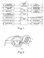
- Figure 1 is a block diagram illustrating constituent features of a preceding vehicle following cruise control system in accordance with a preferred embodiment of the present invention
- Figure 2 is a schematic diagram of a steering wheel portion of a host vehicle illustrating positional arrangements of a plurality of operating members of the preceding vehicle following cruise control system of the preferred embodiment of the present invention
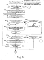
- Figure 3 is a flowchart describing a preceding vehicle following cruise control process executed in the preceding vehicle following cruise control system in accordance with the preferred embodiment of the present invention
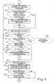
- Figure 4 is a flowchart of the preceding vehicle following cruise control process continued from the flowchart of Figure 3 executed in the preceding vehicle following cruise control system in accordance with the preferred embodiment of the present invention
- Figure 5 is a schematic diagram illustrating an example of an image displayed in a display unit of the preceding vehicle following cruise control system during a high speed following cruise control mode in accordance with the preferred embodiment of the present invention
- Figure 6 is a schematic diagram illustrating an example of an image displayed in the display unit of the preceding vehicle following cruise control system during a low speed following cruise control mode in accordance with the preferred embodiment of the present invention.
- Figure 7 is a schematic diagram illustrating an example of an image displayed in the display unit of the preceding vehicle following cruise control system during an automatic shifting ready state in which the preceding vehicle following cruise control system is ready to automatically shift from the low speed following cruise control mode to the high speed following cruise control mode in accordance with the preferred embodiment of the present invention.
- a total range of vehicle speeds in which a preceding vehicle following cruise control (i.e., the following cruise control) is executed is divided into two regions, i.e., a low speed region and a high speed region.
- the preceding vehicle following control system is configured to selectively execute a following cruise control mode for the low speed region (hereinafter called “low speed following cruise control mode") and a following cruise control mode for the high speed region (hereinafter called “high speed following cruise control mode”) so that the following cruise control is executed in all speed regions of the total range of vehicle speeds.
- total range of vehicle speeds means a substantially entire range of vehicle speeds that ranges from a minimum vehicle speed at which the following cruise control is executed to a maximum vehicle speed at which the following cruise control is executed.
- the minimum vehicle speed of the total range of vehicle speeds is set to 0 km/h or a very low speed (e.g., 10 km/h)
- the maximum vehicle speed of the total range of vehicle speeds is set to a legal speed limit (e.g., 100 km/h) or a higher speed.
- the low speed following cruise control mode is used in a low speed region that ranges from the minimum vehicle speed (i.e., 10 km/h in this preferred embodiment) at which preceding vehicle following cruise control is executed to the upper speed limit for the low speed following cruise control mode (i.e., 40 km/h in this preferred embodiment).
- the preceding vehicle following cruise control system is configured to execute the following cruise control such that a vehicle in which the cruise control system is installed (hereinafter referred as "host vehicle”) follows a preceding vehicle while maintaining a preset following distance when the preceding vehicle is detected in front of the host vehicle, and to abort the following cruise control when the preceding vehicle is not detected in front of the host vehicle.
- host vehicle a vehicle in which the cruise control system is installed
- the high speed following cruise control mode is also called an adaptive cruise control (ACC) mode, and is used in a high speed region that ranges from a lower speed limit (e.g., 35 km/h in the first embodiment) for the high speed following cruise control mode to the maximum vehicle speed (e.g., 110 km/h in the first embodiment) of the total range of vehicle speeds.
- ACC adaptive cruise control
- the preceding vehicle following cruise control system is configured to execute the preceding vehicle following cruise control in which one of a constant speed cruise control and the following cruise control is executed depending on whether the preceding vehicle is detected.
- the preceding vehicle following cruise control system is configured to execute the constant speed cruise control such that the host vehicle travels in a constant-speed state at a vehicle cruising speed (hereinafter called “vehicle speed setting") for the high speed following cruise control mode when the preceding vehicle is not detected in front of the host vehicle, and to execute the following cruise control such that the host vehicle follows the preceding vehicle while maintaining a preset following distance (first prescribed following distance) when the preceding vehicle is detected.
- vehicle speed setting vehicle cruising speed
- a driver of the host vehicle can set the vehicle speed-setting to any desired speed between the lower speed limit of the high speed following cruise control mode (i.e., 35 km/h in this preferred embodiment) and the maximum vehicle speed (i.e., 110 km/h in this preferred embodiment) at which the preceding vehicle following cruise control is executed.
- This preferred embodiment presents an example in which the upper speed limit of the low speed following cruise control mode is 40 km/h and the lower speed limit of the high speed following cruise control mode is 35 km/h such that the total range of vehicle speeds at which preceding vehicle following cruise control is executed is divided into two overlapping regions, i.e., such that the low speed region and the high speed region overlap each other.
- the low speed region can be set to range from 10 to 40 km/h and the high speed region can be set to range from 40 km/h to 110 km/h.
- FIG. 1 is a block diagram illustrating constituent components of the preceding vehicle following cruise control system in accordance with the preferred embodiment.
- the preceding vehicle following cruise control system of the preferred embodiment has a following following cruise control controller 10 that is operatively coupled to various sensors and switches including a following distance radar 1, a vehicle speed sensor 2, a main switch 3, a resume/accelerate switch 4, a cancel switch 5, a set/coast switch 6 and a brake switch 7.
- the following following cruise control controller 10 is also operatively coupled to an engine control unit 11, a transmission control unit 12, a brake control unit 13, a navigation system 14, a VICS (Vehicle Information and Communication System) receiver 15 and a display unit 16.
- VICS Vehicle Information and Communication System
- the following distance radar 1 is configured and arranged to sweep a laser beam in front of the host vehicle to detect a preceding vehicle and to detect a distance from the host vehicle to the preceding vehicle (i.e., the following distance).
- a milliwave following distance radar that uses milliwaves can be used for the following distance radar 1 to detect the following distance instead of a laser beam radar.
- the vehicle speed sensor 2 is configured and arranged to detect a traveling speed of the host vehicle.
- the main switch 3 is an operating member for starting the preceding vehicle following cruise control system. When the main switch 3 is on, power is being supplied to the preceding vehicle following cruise control system.
- the resume/accelerate switch 4 is an operating member used to resume the preceding vehicle following cruise control at the same vehicle speed setting as was previously used or to increase the vehicle speed setting. More specifically, if the preceding vehicle following cruise control is not in progress when the resume/accelerate switch 4 is operated, the preceding vehicle following cruise control is resumed using the vehicle speed setting for the high speed following cruise control mode that was used the previous time the high speed following cruise control mode was executed. On the other hand, if the preceding vehicle following cruise control is in progress when the resume/accelerate switch 4 is operated, the vehicle speed setting used in the constant speed cruise control for the high speed following cruise control mode is increased.
- the cancel switch 5 is an operating member for canceling the preceding vehicle following cruise control.
- the set/coast switch 6 is an operating member used to start the preceding vehicle following cruise control when the preceding vehicle following cruise control is not already in progress and used to reduce the vehicle speed setting used in the constant speed cruise control for the high speed following cruise control mode when the preceding vehicle following cruise control is already in progress.
- the set/coast switch 6 is operated while the preceding vehicle following cruise control is not in progress, the preceding vehicle following cruise control starts if the preceding vehicle is detected and the constant speed cruise control starts by setting the vehicle speed setting to a vehicle speed at that time if the preceding vehicle is not detected in the high speed region.
- the constant speed cruise control is configured to control the host vehicle to travel at the vehicle speed setting in the high speed following cruise control mode.
- the resume/accelerate switch 4, the cancel switch 5, and the set/coast switch 6 are preferably provided on a spoke portion of the steering wheel of the host vehicle as shown in Figure 2 so that the driver of the host vehicle can operate the resume/accelerate switch 4, the cancel switch 5, and the set/coast switch 6 while sitting on a driver's seat.
- the brake switch 7 is turned on when the brake pedal (not shown) is depressed.
- the cancel switch 5 is an operating member for canceling the preceding vehicle following cruise control.
- the set/coast switch 6 is an operating member used to start preceding vehicle following cruise control when preceding vehicle following cruise control is not already in progress and to reduce the vehicle speed setting used for constant speed control when preceding vehicle following cruise control is already in progress.
- preceding vehicle following cruise control starts if a preceding vehicle exists and constant speed cruise control using the current vehicle speed as the vehicle speed setting starts if a preceding vehicle does not exist.
- the resume/accelerate switch 4, the cancel switch 5, and the set/coast switch 6 are provided on the spoke portion of a steering wheel 20.
- the brake switch 7 is turned on when the brake pedal (not shown) is depressed.
- the following cruise control controller 10 preferably includes a microcomputer with the preceding vehicle following cruise control program and the constant speed cruise control program described above to control the preceding vehicle following cruise control system as discussed below. More specifically, as seen in Figure 1, the following cruise control controller 10 includes a CPU 10a, a ROM (Read Only Memory) 10b, and a RAM (Random Access Memory) 10c. The following cruise control controller 10 can also include other conventional components such as an input interface circuit, an output interface circuit, and the like.
- the microcomputer of the following cruise control controller 10 is programmed to control the preceding vehicle following cruise control.
- the memory circuit stores processing results and control programs such as ones for the preceding vehicle following cruise control operation that are run by the processor circuit.
- the following cruise control controller 10 is operatively coupled to the various sensors and switches in a conventional manner.
- the internal RAM 10c of the following cruise control controller 10 stores statuses of operational flags and various control data.
- the internal ROM 10b of the cruise control controller stores the various data and maps for various operations.
- the following cruise control controller 10 is capable of selectively controlling any of the components of the preceding vehicle following cruise control system in accordance with the control program. It will be apparent to those skilled in the art from this disclosure that the precise structure and algorithms for the following cruise control controller 10 can be any combination of hardware and software that will carry out the functions of the present invention. In other words, "means plus function" clauses as utilized in the specification and claims should include any structure or hardware and/or algorithm or software that can be utilized to carry out the function of the "means plus function” clause.
- the engine control unit 11 is configured to execute air intake quantity control, fuel injection control, and ignition timing control of an engine (not shown) to regulate the output torque and the rotational speed of the engine and to control the drive force of the host vehicle.
- the transmission control unit 12 is configured to control the gear ratio, i.e., shift position, of an automatic transmission (not shown) of the host vehicle.
- the brake control unit 13 is configured to control the braking force of the host vehicle by adjusting the brake fluid pressure.
- the navigation device 14 is configured to detect the current position of the host vehicle and to provide information regarding map/traffic information such as the legal speed limit of the road on which the host vehicle is traveling.
- the VICS receiver 15 is configured to receive traffic congestion information from a light beacon, radio wave beacon, or FM multiplexed broadcast, and the like.
- the display unit 16 is configured to indicate the control state of the preceding vehicle following cruise control system and the cruising state of the host vehicle.
- the following cruise control controller 10 is configured to shift to the preceding vehicle following cruise control in the low speed following cruise control mode unconditionally when the speed of the host vehicle falls to 40 km/h or less while the preceding vehicle following cruise control is executed in the high speed following cruise control mode.
- the following cruise control controller 10 is not configured to shift unconditionally to the preceding vehicle following cruise control in the high speed following cruise control mode when the speed of the host vehicle rises to 40 km/h or higher while the preceding vehicle following cruise control is executed in the low speed following cruise control mode. In the latter case, the preceding vehicle following cruise control system will not shift automatically unless the vehicle speed setting is stored in a prescribed address of the RAM 10c.
- the driver When the vehicle speed setting is stored in the RAM 10c, the driver has experienced the following cruise control in the high speed following cruise control mode at least once during the current driving session. Thus, it is reasonable to believe that the driver will not feel uncomfortable if the host vehicle shifts automatically from the low speed following cruise control mode to the high speed following cruise control mode. As a result, there is no need for the driver to manually operate the set/coast switch 6 in order to shift to the high speed following cruise control mode when there is no reason why shifting automatically to the high speed following cruise control mode should be a problem. Thus, the preceding vehicle following cruise control system of the present invention is more convenient with respect to switching (changing) the following cruise control mode from the low speed region to the high speed region.
- Figures 3 and 4 are the flowchart describing a control process executed in the following cruise control controller 10 for executing the preceding vehicle following cruise control in accordance with this preferred embodiment.
- the following cruise control controller 10 is configured to start executing the program illustrated in Figures 3 and 4 when the set/coast switch 6 is operated at a time when the preceding vehicle following cruise control is not already being executed.
- step S1 of Figure 3 the following cruise control controller 10 is configured to check the current vehicle speed detected by the vehicle speed sensor 2 and to determine if the host vehicle speed is larger than 40 km/h, i.e., if the vehicle is traveling at a high speed that is larger than the upper speed limit of the low speed region. If the host vehicle is traveling at a high speed in step S1, the following cruise control controller 10 is configured to proceed to step S2. In step S2, the following cruise control controller 10 is configured to execute the processing required to start the preceding vehicle following cruise control in the high speed following cruise control mode.
- step S1 the following cruise control controller 10 is configured to proceed to step S21 of Figure 4 and to execute the processing required to start the preceding vehicle following cruise control in the low speed following cruise control mode.
- step S2 the following cruise control controller 10 is configured to store the current vehicle speed detected by the vehicle speed sensor 2 as a cruising speed that is used for the constant speed cruise control in the high speed following cruise control mode (i.e., the "vehicle speed setting") in a prescribed address of the RAM 10c.
- step S3 the following cruise control controller 10 is configured to start executing the preceding vehicle following cruise control in the high speed following cruise control mode. More specifically, the following cruise control controller 10 is configured to execute a following distance control such that the following distance detected by the following distance radar 1 matches a preset target following distance and the host vehicle follows the preceding vehicle.
- the display unit 16 When the preceding vehicle following cruise control system is executing the preceding vehicle following cruise control in the high speed following cruise control mode, the display unit 16 is configured and arranged to display an indicator or mark indicating that the preceding vehicle following cruise control system is in the high speed following cruise control mode as shown in Figure 5.
- Figure 5 illustrates an example of an image displayed in the display unit 16 when the following cruise control is being executed in the high speed following cruise control mode with the vehicle speed setting of 100 km/h.
- step S4 the following cruise control controller 10 is configured to check if the cancel switch 5 has been operated (i.e., if the cancel switch 5 is on) or if the brake pedal has been depressed and the brake switch 7 is on. If the cancel switch 5 or the brake switch 7 is on in step S4, the following cruise control controller 10 is configured to proceed to step S5. In step S5, the following cruise control controller 10 is configured to cancel the preceding vehicle following cruise control in the high speed following cruise control mode and to end the control sequence.
- step S4 the following cruise control controller 10 is configured to proceed to step S6 and to determine if the main switch 3 has been turned off. If the main switch 3 is off in step S6, the following cruise control controller 10 is configured to proceed to step S7. In step S7, the following cruise control controller 10 is configured to erase the vehicle speed setting stored in the prescribed address of the RAM 10c and to proceed to step S5 where the following cruise control controller 10 is configured to cancel the preceding vehicle following cruise control in the high speed following cruise control mode and to end the control sequence.
- the following cruise control controller 10 is configured to proceed to step S8 and to determine if the following distance radar 1 has lost sight of (no longer detects) the preceding vehicle. If the preceding vehicle is no longer detected, the following cruise control controller 10 is configured to proceed to step S9. In step S9, the following cruise control controller 10 is configured to execute a vehicle speed control such that the vehicle speed detected by the vehicle speed sensor 2 matches the vehicle speed setting stored in the prescribed address of the RAM 10c, and thus, the host vehicle travels at a constant speed (the constant speed cruise control).
- step S10 the following cruise control controller 10 is configured to check if a preceding vehicle has been detected again by the following distance radar 1 during the constant speed cruise control. If a preceding vehicle is detected, the following cruise control controller 10 is configured to return to step S3 and to execute the following distance control such that the following distance detected by the following distance radar 1 matches the preset target following distance and the host vehicle follows the preceding vehicle. On the other hand, if a preceding vehicle is still not detected in step S 10, the following cruise control controller 10 returns to step S4 and to repeat the processing steps just described above.
- step S8 the following cruise control controller 10 is configured to proceed to step S11 and to check if the current vehicle speed detected by the vehicle speed sensor 2 is equal to or less than 35 km/h. If the vehicle speed exceeds 35 km/h in step S11, the following cruise control controller 10 is configured to return to step S4 and to repeat the processing steps described above. Conversely, if the vehicle speed is equal to or less than 35 km/h in step S 11, the following cruise control controller 10 is configured to proceed to step S21 of Figure 4 and thereby shift from the high speed following cruise control mode to the low speed following cruise control mode.
- the following cruise control controller 10 is configured to execute the following distance control such that the following distance detected by the following distance radar 1 matches a preset target following distance and the host vehicle follows the preceding vehicle using the low speed following cruise control mode
- step S1 If the set/coast switch 6 is operated when the preceding vehicle following cruise control is not in progress and it is determined in step S1 that the host vehicle is not traveling at a high speed of 35 km/h or higher, the following cruise control controller 10 proceeds to step S21 and to start the preceding vehicle following cruise control in the low speed following cruise control mode.
- the display unit 16 is configured to display an indicator or mark like that shown in Figure 6 to inform the driver of the host vehicle that the preceding vehicle following cruise control system is in the low speed following cruise control mode. While the mark indicating the high speed following cruise control mode shown in Figure 5 displays the vehicle speed setting (100 km/h in Figure 5), the mark indicating the low speed following cruise control mode does not display the vehicle speed setting because the vehicle speed setting is not in effect in the low speed following cruise control mode. Thus, the driver can recognize which one of the following cruise control modes is in progress based on whether or not the vehicle speed setting is displayed in the display unit 16.
- the preceding vehicle following cruise control system When the preceding vehicle following cruise control system is executing the preceding vehicle following cruise control in the low speed following cruise control mode while the vehicle speed setting is stored in the prescribed address of the RAM 10c (i.e., when an automatic mode shifting condition is satisfied), the preceding vehicle following cruise control system is configured to shift automatically from the low speed following cruise control mode to the high speed following cruise control mode when the vehicle speed exceeds 40 km/h.
- automatically shift means the shifting from the high speed following control mode to the low speed following control mode is executed without the driver operating the operation members (such as the resume/accelerate switch 4).
- an indicator or mark like that shown in Figure 7 is displayed on the display unit 16 to inform the driver that the following cruise control can be shift automatically from the low speed following cruise control mod to the high speed following cruise control mode.
- the mark shown in Figure 7 consists of the mark for the low speed following cruise control mode shown in Figure 6 with an "ACC" indicator added thereto.
- the mark shown in Figure 7 enables the driver to recognize that the preceding vehicle following cruise control system is currently executing the preceding vehicle following cruise control in the low speed following cruise control mode and that the preceding vehicle following cruise control system is ready to shift automatically to the high speed following cruise control mode at any time if the vehicle speed exceeds 40 km/h.
- the following cruise control controller 10 is configured to proceed to step S22 and to check if either the cancel switch 5 or the brake switch 7 is on, if the main switch 3 is off, and if the following distance radar 1 has lost sight of the preceding vehicle. If the cancel switch 5 has been operated, the brake pedal has been depressed, the main switch 3 has been operated, or the preceding vehicle is not longer detected in step S22, then the following cruise control controller 10 is configured to proceed to step S23. In step S23, the following cruise control controller 10 is configured to cancel the preceding vehicle following cruise control in the low speed following cruise control mode and to end the control sequence.
- step S24 the following cruise control controller 10 is configured to proceed to step S24.
- step S24 the following cruise control controller 10 is configured to acquire road information regarding the road on which the host vehicle is traveling from the navigation device 14 and the VICS receiver 15.
- step S25 the following cruise control controller 10 is configured to extract the legal speed limit of the road from the road information and to determine if the legal speed limit is equal to or lower than 40 km/h.
- the upper speed limit of the low speed following cruise control mode is set to be 40 km/h.
- the following cruise control controller 10 is configured to proceed to step S21 and to continue executing the preceding vehicle following cruise control in the low speed following cruise control mode because, depending on the vehicle speed setting, the vehicle speed might exceed the legal speed limit if the preceding vehicle following cruise control system shifts from the low speed following cruise control mode to the high speed following cruise control mode while the host vehicle is traveling on the road whose legal speed limit is 40 km/h or lower.
- step S25 the legal speed limit is determined to be over 40 km/h
- the following cruise control controller 10 is configured to proceed to step S26 and to check if the vehicle speed setting is stored in the prescribed address of the RAM 10c. If the vehicle speed setting is not stored in the prescribed address of the RAM 10c in step S26, the following cruise control controller 10 is configured to proceed to step S31.
- step S31 the following cruise control controller 10 is configured to determine if the current vehicle speed detected by the vehicle speed sensor 2 is in the region ranging from 35 to 40 km/h (i.e., the overlapping region between the high speed region and the low speed region). The following cruise control controller 10 is configured to proceed to step S32 if the vehicle speed is in the overlapping region, and to return to step S21 to continue the preceding vehicle following control in the low speed following cruise control mode if the vehicle speed is not in the overlapping region.
- step S32 the following cruise control controller 10 is configured to determine if a shift switch (e.g., the resume/accelerate switch 4) configured to allow the driver to instruct the preceding vehicle following cruise control system to shift to the high speed following cruise control mode has been operated. If the shift switch has been operated, the following cruise control controller 10 is configured to proceed to step S33.
- a shift switch e.g., the resume/accelerate switch 4
- step S33 the following cruise control controller 10 is configured to store a prescribed vehicle speed, e.g., 40 km/h (the upper speed limit of the low speed following cruise control mode), as the vehicle speed setting in the prescribed address of the RAM 10c. Then, the following cruise control controller 10 is configured to proceed to step S4 to execute the preceding vehicle following control in the high speed following cruise control mode. On the other hand, if it is determined that the shift switch has not been operated in step S32, the following cruise control controller 10 is configured to return to step S21 and to continue executing the preceding vehicle following control in the low speed following cruise control mode.
- a prescribed vehicle speed e.g. 40 km/h (the upper speed limit of the low speed following cruise control mode)
- step S26 If in step S26 it finds that a vehicle speed setting is stored in the prescribed address of the RAM 10c, the following cruise control controller 10 is configured to proceed to step S27 and to check if the current vehicle speed detected by the vehicle speed sensor 2 exceeds 40 km/h. If the vehicle speed does not exceed 40 km/h in step S27, the following cruise control controller 10 is configured to return to step S21 and to continue executing the preceding vehicle following control in the low speed following cruise control mode. Conversely, if the vehicle speed exceeds 40 km/h in step S27, the following cruise control controller 10 is configured to proceed to step S28 and to automatically shift from the low speed following cruise control mode to the high speed following cruise control mode. More specifically, in step S28, the following cruise control controller 10 is configured to execute the following distance control such that the following distance detected by the following distance radar 1 matches a preset target following distance and the vehicle follows the preceding vehicle using the high speed following cruise control mode.
- the display unit 16 is configured to display the indicator indicating that the preceding vehicle following cruise control system is in the high speed following cruise control mode as shown in Figure 5.
- Figure 5 illustrates a case in which high speed following cruise control is being executed with the vehicle speed setting of, for example, 100 km/h.
- the following cruise control controller 10 is configured to determine if the vehicle speed setting exceeds the legal speed limit of the road on which the host vehicle is traveling. If the vehicle speed setting exceeds the legal speed limit in step S29, the following cruise control controller 10 is configured to proceed to step S30 and to limit the vehicle speed to a speed equal to or lower than the legal speed limit. Then, the following cruise control controller 10 is configured to return to step S4 and to repeat the processing described previously.
- the preceding vehicle following cruise control system of this preferred embodiment is configured to automatically shift from the low speed following cruise control mode to the high speed following cruise control mode when the vehicle speed enters the high speed region from the low speed region while the vehicle speed setting has been set (i.e., the vehicle speed setting is stored in the prescribed address of the RAM 10c).
- the preceding vehicle following cruise control system is configured to shift to the high speed following cruise control mode automatically without the need for the driver to change the mode manually by operating the set/coast switch 6.
- the preceding vehicle following cruise control system is more convenient with respect to switching (changing) between the low speed following cruise control mode and the high speed following cruise control mode.
- the preceding vehicle following cruise control system is configured to detect the legal speed limit of the road on which the host vehicle is traveling and does not automatically shift from the low speed following cruise control mode to the high speed following cruise control mode if the legal speed limit of the road on which the host vehicle is traveling is equal to or lower than the upper speed limit of the low speed region (i.e., 40 km/h in this preferred embodiment). As a result, a situation in which the host vehicle accelerates to a vehicle speed exceeding the legal speed limit while following the preceding vehicle can be prevented.
- the preceding vehicle following cruise control system is configured to detect the legal speed limit of the road on which the host vehicle is traveling and to limit the vehicle speed to the legal speed limit if the vehicle speed setting exceeds the legal speed limit after the following cruise control mode switches from the low speed following cruise control mode to the high speed following cruise control mode. As a result, a situation in which the host vehicle accelerates to a vehicle speed exceeding the legal speed limit while following the preceding vehicle can be prevented.
- the driver is informed when the preceding vehicle following cruise control system shifts automatically from the low speed following cruise control mode to the high speed following cruise control mode.
- the driver can be made aware that the following cruise control mode has shifted (changed) and will not experience an uncomfortable feeling if the host vehicle accelerates automatically in order to follow a preceding vehicle after the automatic mode shift from the low speed following cruise control mode to the high speed following cruise control mode.
- the driver is informed when the preceding vehicle following cruise control system is in a state in which the preceding vehicle following cruise control system can shift automatically from the low speed following cruise control mode to the high speed following cruise control mode.
- the driver can be aware that the mode may shift automatically to the high speed following cruise control mode and will not experience an uncomfortable feeling if the host vehicle accelerates automatically in order to follow a preceding vehicle after the mode shifts automatically.
- the vehicle speed sensor 2 preferably corresponds to the vehicle speed detecting section of the present invention.
- the following distance radar 1 preferably corresponds to the preceding vehicle detecting section of the present invention.
- the following cruise control controller 10 preferably corresponds to the following cruise control section, the constant speed cruise control section, the mode switching section, and the vehicle speed limiting section of the present invention.
- the navigation unit 14 and the VICS receiver 15 preferably correspond to the road information detecting section of the present invention.
- the display unit 16 preferably corresponds to the reporting section of the present invention.
- the set/coast switch 6 preferably corresponds to the mode switching operating member of the present invention.
- the RAM 10c preferably corresponds to the memory section of the present invention.
- the constituent elements are not limited to those described herein so long as the characteristic functions of the present invention are not lost.
- the preferred embodiment described herein presents an example in which the preceding vehicle following cruise control system in accordance with the present invention is applied to an automobile that uses an engine as a drive source
- the invention can also be applied to hybrid vehicles and electric vehicles in addition to engine-powered vehicles.
- the preferred embodiment described herein presents an example in which the total range of vehicle speeds at which the preceding vehicle speed following cruise control is executed is divided into two vehicle speed regions, i.e., the high speed region (high speed following cruise control mode) and the low speed region (low speed following cruise control mode), it is also acceptable to divide the total range of vehicle speeds into three or more speed regions.
- the invention is not limited to the specific values mentioned in the preferred embodiment regarding the maximum vehicle speed and minimum vehicle speed at which preceding vehicle following cruise control is executed and the upper speed limit, lower speed limit, and vehicle speed setting of the high and low speed following cruise control modes.
- the preceding vehicle following cruise control system is configured to shift automatically from the low speed following cruise control mode to the high speed following cruise control mode when the vehicle speed enters the high speed region from the low speed region while the vehicle speed setting is set (i.e., while the vehicle speed setting is stored in the prescribed address of the RAM 10c)
- the invention is not limited to such an arrangement. It is also acceptable to configure the preceding vehicle following cruise control system such that when the driver performs an operation for changing the following cruise control mode between the low speed following cruise control mode and the high speed following cruise mode, the fact that the mode switching operation occurred, i.e., a mode switching operation history, is stored in, for example, the RAM 10c.
- step S26 of Figure 4 should be replaced with step S26' in which the following cruise control controller 10 is configured to determine if the mode switching operation history is stored in the RAM 10c.
- the preceding vehicle following cruise control system of the present invention can be configured to determine the automatic mode shift condition is satisfied when the mode switching operation history is stored in the RAM 10c
- the preceding vehicle following cruise control system of the present invention is configured to automatically shift from the low speed following cruise control mode to the high speed following cruise control mode when the vehicle speed changes from the low speed region to the high speed region while the vehicle speed setting is set.
- the preceding vehicle following cruise control system in accordance with the present invention is configured shift automatically from a low speed following cruise control mode to the high speed following cruise control mode when the vehicle speed changes from the low speed region to the high speed region while the mode switching operation history indicating that the following cruise control mode has been changed from the low speed following cruise control mode to the high speed following cruise control mode by operating the mode switching operating member is stored in the memory section (i.e., the RAM 10c).
- the preceding vehicle following cruise control system is configured to shift to the high speed following cruise control mode automatically without the need for the driver to change the mode manually by operating a mode switching operating member.
- the system is more convenient with respect to switching (changing) the following cruise control mode.
- detect as used herein to describe an operation or function carried out by a component, a section, a device or the like includes a component, a section, a device or the like that does not require physical detection, but rather includes determining, measuring, modeling, predicting or computing or the like to carry out the operation or function.
Landscapes
- Engineering & Computer Science (AREA)
- Transportation (AREA)
- Mechanical Engineering (AREA)
- Chemical & Material Sciences (AREA)
- Combustion & Propulsion (AREA)
- Automation & Control Theory (AREA)
- Controls For Constant Speed Travelling (AREA)
- Control Of Driving Devices And Active Controlling Of Vehicle (AREA)
- Control Of Vehicle Engines Or Engines For Specific Uses (AREA)
- Traffic Control Systems (AREA)
Claims (7)
- Fahrtregelungssystem zum Nachfolgen eines vorausfahrenden Fahrzeugs, umfassend:einen Fahrzeuggeschwindigkeit-Erfassungsbereich, der ausgelegt und angeordnet ist, eine Fahrzeuggeschwindigkeit eines Host-Fahrzeugs zu erfassen (Schritte S1, S11, S31);einen Erfassungsbereich für ein vorausfahrendes Fahrzeugs, der ausgelegt und angeordnet ist, ein vor dem Host-Fahrzeug befindliches vorausfahrendes Fahrzeug zu erfassen(Schritt S8); undeinen Nachfolge-Fahrtregelungsbereich, der ausgelegt und angeordnet ist, wahlweise, basierend auf einer Fahrbedingung, einen Hochgeschwindigkeit-Nachfolge-Fahrtregelungsmodus in einem Hochgeschwindigkeitsgebiet oder einen Niedriggeschwindigkeit-Nachfolge-Fahrtregelungsmodus in einem Niedriggeschwindigkeitsgebiet auszuführen, und automatisch von dem Niedriggeschwindigkeit-Nachfolge-Fahrtregelungsmodus zu dem Hochgeschwindigkeit-Nachfolge-Fahrtregelungsmodus zu schalten, wenn eine Automatikmodus-Schaltbedingung, die anzeigt, dass der Hochgeschwindigkeit-Nachfolge-Fahrtregelungsmodus vorher ausgeführt wurde, erfüllt ist, und wenn die Fahrzeuggeschwindigkeit von dem Niedriggeschwindigkeitsgebiet zu dem Hochgeschwindigkeitsgebiet wechselt (Schritte S26, S26', S27, S28).
- Fahrtregelungssystem zum Nachfolgen eines vorausfahrenden Fahrzeugs gemäß Anspruch 1, wobei
der Nachfolge-Fahrtregelungsbereich ferner ausgelegt ist, wahlweise
den Hochgeschwindigkeit-Nachfolge-Fahrtregelungsmodus in dem Hochgeschwindigkeitsgebiet auszuführen, in dem eine Nachfolge-Fahrtregelung derart ausgeführt wird, dass das Host-Fahrzeug dem vorausfahrenden Fahrzeug folgt, während es einen ersten vorgeschriebenen Nachfolgeabstand beibehält, wenn das vorausfahrende Fahrzeug erfasst ist, und wobei eine Konstantgeschwindigkeit-Fahrtregelung derart ausgeführt wird, dass das Host-Fahrzeug in einem Zustand konstanter Geschwindigkeit bei einer Fahrzeuggeschwindigkeitseinstellung fährt, wenn das vorausfahrende Fahrzeug nicht erfasst ist,
oder den Niedriggeschwindigkeit-Nachfolge-Fahrtregelungsmodus in dem Niedriggeschwindigkeitsgebiet auszuführen, in dem eine Nachfolge-Fahrtregelung derart ausgeführt wird, dass das Host-Fahrzeug dem vorausfahrenden Fahrzeug folgt, während es einen zweiten vorgeschriebenen Nachfolgeabstand beibehält, wenn das vorausfahrende Fahrzeug erfasst ist, und wobei die Nachfolge-Fahrtregelung abgebrochen wird, wenn das vorausfahrende Fahrzeug nicht erfasst ist, und wobei
der Nachfolge-Fahrtregelungsbereich ferner ausgelegt ist, zu bestimmen, dass die Automatikmodus-Schaltbedingung erfüllt ist, wenn die Fahrzeuggeschwindigkeitseinstellung eingestellt worden ist (Schritt S26). - Fahrtregelungssystem zum Nachfolgen eines vorausfahrenden Fahrzeugs gemäß Anspruch 1 oder 2, ferner umfassend:ein Modusumschaltung-Betätigungselement (4), das ausgelegt und angeordnet ist, eine Anweisung zum Umschalten von dem Niedriggeschwindigkeit-Nachfolge-Fahrtregelungsmodus zu dem Hochgeschwindigkeit-Nachfolge-Fahrtregelungsmodus auszugeben, undeinen Speicherbereich (10c), der ausgelegt und angeordnet ist, eine Historie eines Modusumschaltvorgangs des Umschaltens von dem Niedriggeschwindigkeit-Nachfolge-Fahrtregelungsmodus zu dem Hochgeschwindigkeit-Nachfolge-Fahrtregelungsmodus zu speichern, wenn das Modusumschaltung- Betätigungselement betätigt wird, um von dem Niedriggeschwindigkeit-Nachfolge-Fahrtregelungsmodus zu dem Hochgeschwindigkeit-Nachfolge-Fahrtregelungsmodus umzuschalten,wobei der Nachfolge-Fahrtregelungsbereich ferner ausgelegt ist, zu bestimmen, dass die Automatikmodus-Schaltbedingung erfüllt ist, wenn der Modusumschaltvorgang in dem Speicherbereich gespeichert worden ist (Schritt S26').
- Fahrtregelungssystem zum Nachfolgen eines vorausfahrenden Fahrzeugs gemäß einem der Ansprüche 1 bis 3, ferner umfassend:einen Straßeninformationen-Erfassungsbereich, der ausgelegt und angeordnet ist, eine gültige Geschwindigkeitsbegrenzung einer Straße, auf dem das Host-Fahrzeug fährt, zu erfassen (Schritt S24),wobei der Nachfolge-Fahrtregelungsbereich ferner ausgelegt ist, automatisches Umschalten von dem Niedriggeschwindigkeit-Nachfolge-Fahrtregelungsmodus zu dem Hochgeschwindigkeit-Nachfolge-Fahrtregelungsmodus zu verhindern, wenn die gültige Geschwindigkeitsbegrenzung der Straße gleich oder niedriger als eine obere Geschwindigkeitsbegrenzung des Niedriggeschwindigkeitsgebietes ist (Schritt S25).
- Fahrtregelungssystem zum Nachfolgen eines vorausfahrenden Fahrzeugs gemäß einem der Ansprüche 1, 2 und 4, ferner umfassend:einen Straßeninformationen-Erfassungsbereich, der ausgelegt und angeordnet ist, eine gültige Geschwindigkeitsbegrenzung einer Straße, auf dem das Host-Fahrzeug fährt, zu erfassen (Schritt S24), undeinen Fahrzeuggeschwindigkeit-Begrenzungsbereich, der ausgelegt und angeordnet ist, die Fahrzeuggeschwindigkeit des Host-Fahrzeugs auf die gültige Geschwindigkeitsbegrenzung der Straße zu begrenzen, wenn die Fahrzeuggeschwindigkeitseinstellung die gültige Geschwindigkeitsbegrenzung überschreitet, nachdem der Nachfolge-Fahrtregelungsbereich von dem Niedriggeschwindigkeit-Nachfolge-Fahrtregelungsmodus zu dem Hochgeschwindigkeit-Nachfolge-Fahrtregelungsmodus umschaltet (Schritte S29, S30).
- Fahrtregelungssystem zum Nachfolgen eines vorausfahrenden Fahrzeugs gemäß einem der Ansprüche 1 bis 5, ferner umfassend:einen Meldebereich (16), der ausgelegt und angeordnet ist, einem Fahrer des Host-Fahrzeugs zu melden, dass der Nachfolge-Fahrtregelungsbereich automatisch von dem Niedriggeschwindigkeit-Nachfolge-Fahrtregelungsmodus zu dem Hochgeschwindigkeit-Nachfolge-Fahrtregelungsmodus geschaltet hat.
- Fahrtregelungssystem zum Nachfolgen eines vorausfahrenden Fahrzeugs gemäß einem der Ansprüche 1 bis 6, ferner umfassend:einen Meldebereich (16), der ausgelegt und angeordnet ist, einem Fahrer des Host-Fahrzeugs zu melden, dass ein automatisches Schalten von dem Niedriggeschwindigkeit-Nachfolge-Fahrtregelungsmodus zu dem Hochgeschwindigkeit-Nachfolge-Fahrtregelungsmodus ausgeführt werden kann.
Applications Claiming Priority (1)
| Application Number | Priority Date | Filing Date | Title |
|---|---|---|---|
| JP2004209971A JP4453468B2 (ja) | 2004-07-16 | 2004-07-16 | 先行車追従走行制御装置 |
Publications (2)
| Publication Number | Publication Date |
|---|---|
| EP1616744A1 EP1616744A1 (de) | 2006-01-18 |
| EP1616744B1 true EP1616744B1 (de) | 2007-03-14 |
Family
ID=35056845
Family Applications (1)
| Application Number | Title | Priority Date | Filing Date |
|---|---|---|---|
| EP05015339A Not-in-force EP1616744B1 (de) | 2004-07-16 | 2005-07-14 | Abstandsbezogenes Fahrgeschwindigkeitsregelsystem |
Country Status (6)
| Country | Link |
|---|---|
| US (1) | US7460946B2 (de) |
| EP (1) | EP1616744B1 (de) |
| JP (1) | JP4453468B2 (de) |
| KR (1) | KR100618020B1 (de) |
| CN (1) | CN100515817C (de) |
| DE (1) | DE602005000709T2 (de) |
Families Citing this family (44)
| Publication number | Priority date | Publication date | Assignee | Title |
|---|---|---|---|---|
| US6591168B2 (en) * | 2001-08-31 | 2003-07-08 | Intellisist, Inc. | System and method for adaptable mobile user interface |
| US20040084237A1 (en) * | 2002-05-30 | 2004-05-06 | Petrie Alfred E. | Vehicle cruise control system |
| JP4453468B2 (ja) * | 2004-07-16 | 2010-04-21 | 日産自動車株式会社 | 先行車追従走行制御装置 |
| JP2006027457A (ja) * | 2004-07-16 | 2006-02-02 | Nissan Motor Co Ltd | 車両用走行制御装置 |
| US11370302B2 (en) | 2005-11-17 | 2022-06-28 | Invently Automotive Inc. | Electric vehicle power management system |
| US11207980B2 (en) | 2005-11-17 | 2021-12-28 | Invently Automotive Inc. | Vehicle power management system responsive to traffic conditions |
| US11351863B2 (en) | 2005-11-17 | 2022-06-07 | Invently Automotive Inc. | Vehicle power management system |
| US11180025B2 (en) | 2005-11-17 | 2021-11-23 | Invently Automotive Inc. | Electric vehicle power management system |
| US11214144B2 (en) | 2005-11-17 | 2022-01-04 | Invently Automotive Inc. | Electric vehicle power management system |
| US11285810B2 (en) | 2005-11-17 | 2022-03-29 | Invently Automotive Inc. | Vehicle power management system |
| US11345236B2 (en) | 2005-11-17 | 2022-05-31 | Invently Automotive Inc. | Electric vehicle power management system |
| US11186175B2 (en) | 2005-11-17 | 2021-11-30 | Invently Automotive Inc. | Vehicle power management system |
| JP5056220B2 (ja) * | 2006-09-29 | 2012-10-24 | 日産自動車株式会社 | 走行制御装置 |
| DE102006060554A1 (de) * | 2006-12-21 | 2008-06-26 | Bayerische Motoren Werke Ag | Lenkrad für ein Kraftfahrzeug und Kraftfahrzeug |
| US8014928B2 (en) * | 2008-06-17 | 2011-09-06 | Ford Global Technologies, Llc | Automotive slipstreaming support system |
| KR101168744B1 (ko) | 2008-12-03 | 2012-07-26 | 한국전자통신연구원 | 정속 주행 시스템 및 그 방법 |
| KR20120094365A (ko) * | 2011-02-16 | 2012-08-24 | 주식회사 만도 | 가속 제어 조절 방법 및 그 적응 순항 제어 시스템 |
| DE102011084606A1 (de) * | 2011-10-17 | 2013-04-18 | Robert Bosch Gmbh | Bestimmung einer Fahrstrategie für ein Fahrzeug |
| BR112014012321A2 (pt) * | 2011-12-22 | 2017-05-30 | Scania Cv Ab | módulo e método pertencentes a escolha de modo quando determinando valores de referência |
| US9632666B2 (en) * | 2012-02-16 | 2017-04-25 | GM Global Technology Operations LLC | Team-oriented HVAC system |
| KR101997430B1 (ko) * | 2012-11-08 | 2019-10-01 | 현대모비스 주식회사 | 차량의 scc 시스템 및 그 제어방법 |
| KR101997431B1 (ko) * | 2012-11-15 | 2019-10-01 | 현대모비스 주식회사 | 선행차량 추종 속도 재설정 장치 및 방법 |
| DE102013200391B4 (de) * | 2013-01-14 | 2022-02-17 | Robert Bosch Gmbh | Verfahren und Vorrichtung zur adaptiven Geschwindigkeitsregelung eines Kraftfahrzeugs mit manuellem Schaltgetriebe |
| CN104279311B (zh) | 2014-01-30 | 2015-11-25 | 比亚迪股份有限公司 | 车辆中同步器的控制方法及车辆 |
| WO2015113416A1 (en) | 2014-01-30 | 2015-08-06 | Byd Company Limited | Power transmission system for vehicle and vehicle comprising the same |
| CN104276176B (zh) * | 2014-01-30 | 2015-09-02 | 比亚迪股份有限公司 | 车辆及车辆的巡航控制方法 |
| WO2015113414A1 (en) | 2014-01-30 | 2015-08-06 | Byd Company Limited | Power transmission system for vehicle and vehicle comprising the same |
| WO2015113415A1 (en) | 2014-01-30 | 2015-08-06 | Byd Company Limited | Power transmission system for vehicle and vehicle comprising the same |
| WO2015113424A1 (zh) | 2014-01-30 | 2015-08-06 | 比亚迪股份有限公司 | 车辆及其动力传动系统 |
| US9568080B2 (en) | 2014-01-30 | 2017-02-14 | Byd Company Limited | Power transmission system for vehicle and vehicle comprising the same |
| US10670123B2 (en) | 2014-01-30 | 2020-06-02 | Byd Company Limited | Power transmission system for vehicle and vehicle comprising the same |
| CN104276031B (zh) | 2014-01-30 | 2016-01-13 | 比亚迪股份有限公司 | 车辆及其驱动控制方法 |
| US9568066B2 (en) | 2014-09-10 | 2017-02-14 | Byd Company Limited | Power transmission system and vehicle comprising the same |
| WO2016037469A1 (en) | 2014-09-10 | 2016-03-17 | Byd Company Limited | Transmission unit, power transmission system and vehicle comprising the same |
| EP2995487B1 (de) | 2014-09-10 | 2019-02-13 | BYD Company Limited | Kraftübertragungssystem und fahrzeug damit |
| CN104608760B (zh) | 2014-10-20 | 2016-05-25 | 比亚迪股份有限公司 | 混合动力汽车及其换挡控制方法、动力传动系统 |
| JP6356585B2 (ja) * | 2014-11-28 | 2018-07-11 | 株式会社デンソー | 車両の走行制御装置 |
| US20160297438A1 (en) * | 2015-04-13 | 2016-10-13 | Mando Corporation | Active cruise control system in vehicle and method thereof |
| DE112015006729B4 (de) * | 2015-07-24 | 2019-05-16 | Mitsubishi Electric Corporation | Fahrzeugkonstantgeschwindigkeitsbewegungssteuervorrichtung, Fahrzeugkonstantgeschwindigkeitsbewegungssteuerverfahren und Fahrzeugkonstantgeschwindigkeitsbewegungssteuerprogramm |
| JP6814224B2 (ja) * | 2016-03-03 | 2021-01-13 | ボルボトラックコーポレーション | 自律走行能力を有する車両 |
| US10059330B2 (en) | 2016-09-22 | 2018-08-28 | Toyota Motor Engineering & Manufacturing North America, Inc. | Drafting detection and vehicle operation optimization system |
| DE102017216215A1 (de) * | 2017-09-13 | 2019-03-14 | Volkswagen Aktiengesellschaft | Verfahren und Vorrichtung zum Anzeigen von Beschleunigungen vorausfahrender Fahrzeuge in einem Fahrzeug |
| CN111823862B (zh) * | 2018-07-18 | 2022-11-15 | 上海东方航空设备制造有限公司 | 一种机动车限速方法、装置、计算机设备及存储介质 |
| CN113212436A (zh) * | 2021-06-23 | 2021-08-06 | 蔚来汽车科技(安徽)有限公司 | 驾驶辅助控制方法及设备 |
Family Cites Families (36)
| Publication number | Priority date | Publication date | Assignee | Title |
|---|---|---|---|---|
| JPS624948A (ja) * | 1985-06-28 | 1987-01-10 | Toyota Motor Corp | 回転速度センサの異常判定装置 |
| US4934476A (en) * | 1987-09-29 | 1990-06-19 | Aisin Seiki Kabushiki Kaisha | Vehicle speed control system |
| JP2837164B2 (ja) * | 1988-04-22 | 1998-12-14 | 富士通テン株式会社 | 自動車の車間距離制御装置 |
| US4947952A (en) * | 1988-09-05 | 1990-08-14 | Mitsubishi Denki Kabushiki Kaisha | Slow speed cruising control apparatus |
| JP2763927B2 (ja) * | 1989-08-08 | 1998-06-11 | 自動車電機工業株式会社 | 車速自動制御装置 |
| JP2987778B2 (ja) * | 1990-11-30 | 1999-12-06 | アイシン精機株式会社 | 車両速度制御装置 |
| JP3197307B2 (ja) * | 1991-10-14 | 2001-08-13 | マツダ株式会社 | 移動車の走行制御装置 |
| US5680309A (en) * | 1995-06-07 | 1997-10-21 | Cummins Engine Company, Inc. | Control system for automatic resumption of speed control after gear change |
| US6125321A (en) * | 1996-06-07 | 2000-09-26 | Toyota Jidosha Kabushiki Kaisha | Motor vehicle drive system controller and automatic drive controller |
| JP3468001B2 (ja) * | 1996-12-16 | 2003-11-17 | 日産自動車株式会社 | 車両用走行制御装置 |
| KR19980072358A (ko) * | 1997-03-04 | 1998-11-05 | 김영귀 | 자동 정속 주행 장치 |
| DE19745127A1 (de) * | 1997-10-13 | 1999-04-15 | Daimler Chrysler Ag | Vorrichtung und Verfahren zum Verhindern von Kollisionen eines Fahrzeugs mit einem Hindernis beim Einparken des Fahrzeugs |
| SE512086C2 (sv) * | 1998-05-28 | 2000-01-24 | Volvo Ab | Förfarande och anordning för konstantfarthållning |
| JP3757674B2 (ja) * | 1999-04-12 | 2006-03-22 | 日産自動車株式会社 | 車両の駆動力制御装置 |
| JP3690185B2 (ja) | 1999-05-25 | 2005-08-31 | 日産自動車株式会社 | 先行車追従制御装置 |
| JP2001010369A (ja) * | 1999-06-29 | 2001-01-16 | Jidosha Denki Kogyo Co Ltd | クルーズコントロール装置 |
| JP2001030797A (ja) * | 1999-07-26 | 2001-02-06 | Mazda Motor Corp | 車両の走行制御装置 |
| KR100325222B1 (ko) * | 1999-07-28 | 2002-03-04 | 이계안 | 차량용 자동 변속기의 피스톤 스트로크 동작 검출 장치 및 그 방법 |
| JP3620359B2 (ja) * | 1999-08-10 | 2005-02-16 | 日産自動車株式会社 | 車両用走行制御装置 |
| KR20010056479A (ko) * | 1999-12-15 | 2001-07-04 | 윤장진 | 사고 자동 경고 장치 및 방법 |
| JP2001246961A (ja) * | 2000-03-07 | 2001-09-11 | Denso Corp | 車間制御装置及び記録媒体 |
| JP4187902B2 (ja) * | 2000-04-28 | 2008-11-26 | 本田技研工業株式会社 | 車両用走行制御装置 |
| JP2002012053A (ja) * | 2000-06-29 | 2002-01-15 | Honda Motor Co Ltd | 車両用走行制御装置 |
| US6600988B1 (en) * | 2000-09-26 | 2003-07-29 | Ford Global Technologies, Inc. | Vehicle trajectory control system and method |
| JP3788240B2 (ja) * | 2001-01-18 | 2006-06-21 | 日産自動車株式会社 | 車両用追従走行制御装置 |
| JP2002234358A (ja) | 2001-02-07 | 2002-08-20 | Honda Motor Co Ltd | 車両用追従走行制御装置 |
| JP2002248963A (ja) * | 2001-02-23 | 2002-09-03 | Tokai Rika Co Ltd | 車両用変速機制御装置 |
| JP3965386B2 (ja) * | 2001-09-28 | 2007-08-29 | ジヤトコ株式会社 | 自動変速機の変速制御装置 |
| US6882923B2 (en) * | 2002-10-17 | 2005-04-19 | Ford Global Technologies, Llc | Adaptive cruise control system using shared vehicle network data |
| JP3929870B2 (ja) * | 2002-10-28 | 2007-06-13 | 日産ディーゼル工業株式会社 | 自動変速制御装置 |
| DE10254582A1 (de) | 2002-11-22 | 2004-06-03 | Robert Bosch Gmbh | Geschwindigkeitsregler mit mehreren Betriebsmodi |
| JP2004215350A (ja) * | 2002-12-27 | 2004-07-29 | Sony Corp | 駆動制御装置およびその方法と2輪車 |
| JP4453468B2 (ja) * | 2004-07-16 | 2010-04-21 | 日産自動車株式会社 | 先行車追従走行制御装置 |
| EP1824700B1 (de) * | 2004-12-10 | 2010-03-03 | Volvo Lastvagnar Ab | Verfahren und rechnerprogramm an einem fahrzeug zur einstellung des abstands zu einem fahrzeug davor |
| JP4635721B2 (ja) * | 2005-05-30 | 2011-02-23 | 日産自動車株式会社 | 車両のオートクルーズ装置 |
| JP4857912B2 (ja) * | 2006-05-29 | 2012-01-18 | 日産自動車株式会社 | 自動変速機の出力軸回転速度推定装置及び異常診断装置並びにオートクルーズ制御装置 |
-
2004
- 2004-07-16 JP JP2004209971A patent/JP4453468B2/ja not_active Expired - Fee Related
-
2005
- 2005-07-12 US US11/178,439 patent/US7460946B2/en not_active Expired - Fee Related
- 2005-07-14 EP EP05015339A patent/EP1616744B1/de not_active Not-in-force
- 2005-07-14 DE DE602005000709T patent/DE602005000709T2/de active Active
- 2005-07-15 KR KR1020050064196A patent/KR100618020B1/ko not_active IP Right Cessation
- 2005-07-18 CN CNB2005100980354A patent/CN100515817C/zh not_active Expired - Fee Related
Also Published As
| Publication number | Publication date |
|---|---|
| JP2006027456A (ja) | 2006-02-02 |
| US7460946B2 (en) | 2008-12-02 |
| EP1616744A1 (de) | 2006-01-18 |
| CN1728192A (zh) | 2006-02-01 |
| US20060015241A1 (en) | 2006-01-19 |
| DE602005000709T2 (de) | 2007-12-06 |
| CN100515817C (zh) | 2009-07-22 |
| KR20060050212A (ko) | 2006-05-19 |
| DE602005000709D1 (de) | 2007-04-26 |
| KR100618020B1 (ko) | 2006-09-01 |
| JP4453468B2 (ja) | 2010-04-21 |
Similar Documents
| Publication | Publication Date | Title |
|---|---|---|
| EP1616744B1 (de) | Abstandsbezogenes Fahrgeschwindigkeitsregelsystem | |
| EP1616745B1 (de) | Abstands- und Geschwindigkeitsregelsystem | |
| US6226588B1 (en) | Informing apparatus for cruise control system | |
| JP4864655B2 (ja) | 走行制御装置 | |
| JP2020019392A (ja) | 自動運転システム | |
| US6327530B1 (en) | Apparatus and method for controlling a distance between two traveling vehicles and a recording medium for storing the control method | |
| CN113165666B (zh) | 用于改善机动车的能效的方法、机动车和计算机可读介质 | |
| CN111717026B (zh) | 车辆行驶控制装置 | |
| JP4432872B2 (ja) | 車両の走行制御装置 | |
| JP2006036159A (ja) | 車両の走行制御装置 | |
| US20230147441A1 (en) | Driving force control device | |
| US20230141314A1 (en) | Driving force control device | |
| JP2006137324A (ja) | 加減速度制御装置 | |
| JP2006168509A (ja) | 自動走行制御装置 | |
| US12049135B2 (en) | Display device, display control method, and non-transitory computer-readable recording medium | |
| JP3699988B2 (ja) | オートクルーズ制御装置 | |
| JPH11254996A (ja) | 車間距離調整機能を備えた定速走行制御装置 | |
| JP2005329786A (ja) | 追従走行制御装置 | |
| US20230286505A1 (en) | Driving assistance apparatus | |
| US20230063897A1 (en) | Vehicle | |
| JP3729609B2 (ja) | 車間距離制御装置 | |
| JP2023071549A (ja) | 駆動力制御装置 | |
| JP2008207725A (ja) | 省燃費運転推奨装置 | |
| JP2023102982A (ja) | 運転支援装置 | |
| US20200223436A1 (en) | Vehicle and control device for the same |
Legal Events
| Date | Code | Title | Description |
|---|---|---|---|
| PUAI | Public reference made under article 153(3) epc to a published international application that has entered the european phase |
Free format text: ORIGINAL CODE: 0009012 |
|
| 17P | Request for examination filed |
Effective date: 20050714 |
|
| AK | Designated contracting states |
Kind code of ref document: A1 Designated state(s): AT BE BG CH CY CZ DE DK EE ES FI FR GB GR HU IE IS IT LI LT LU LV MC NL PL PT RO SE SI SK TR |
|
| AX | Request for extension of the european patent |
Extension state: AL BA HR MK YU |
|
| AKX | Designation fees paid |
Designated state(s): DE FR GB |
|
| GRAP | Despatch of communication of intention to grant a patent |
Free format text: ORIGINAL CODE: EPIDOSNIGR1 |
|
| GRAS | Grant fee paid |
Free format text: ORIGINAL CODE: EPIDOSNIGR3 |
|
| GRAA | (expected) grant |
Free format text: ORIGINAL CODE: 0009210 |
|
| AK | Designated contracting states |
Kind code of ref document: B1 Designated state(s): DE FR GB |
|
| REG | Reference to a national code |
Ref country code: GB Ref legal event code: FG4D |
|
| REF | Corresponds to: |
Ref document number: 602005000709 Country of ref document: DE Date of ref document: 20070426 Kind code of ref document: P |
|
| ET | Fr: translation filed | ||
| PLBE | No opposition filed within time limit |
Free format text: ORIGINAL CODE: 0009261 |
|
| STAA | Information on the status of an ep patent application or granted ep patent |
Free format text: STATUS: NO OPPOSITION FILED WITHIN TIME LIMIT |
|
| 26N | No opposition filed |
Effective date: 20071217 |
|
| PGFP | Annual fee paid to national office [announced via postgrant information from national office to epo] |
Ref country code: FR Payment date: 20110727 Year of fee payment: 7 |
|
| PGFP | Annual fee paid to national office [announced via postgrant information from national office to epo] |
Ref country code: GB Payment date: 20110713 Year of fee payment: 7 Ref country code: DE Payment date: 20110706 Year of fee payment: 7 |
|
| GBPC | Gb: european patent ceased through non-payment of renewal fee |
Effective date: 20120714 |
|
| REG | Reference to a national code |
Ref country code: FR Ref legal event code: ST Effective date: 20130329 |
|
| PG25 | Lapsed in a contracting state [announced via postgrant information from national office to epo] |
Ref country code: GB Free format text: LAPSE BECAUSE OF NON-PAYMENT OF DUE FEES Effective date: 20120714 Ref country code: FR Free format text: LAPSE BECAUSE OF NON-PAYMENT OF DUE FEES Effective date: 20120731 Ref country code: DE Free format text: LAPSE BECAUSE OF NON-PAYMENT OF DUE FEES Effective date: 20130201 |
|
| REG | Reference to a national code |
Ref country code: DE Ref legal event code: R119 Ref document number: 602005000709 Country of ref document: DE Effective date: 20130201 |