EP1605524A1 - Element de montage pour un element electroluminescent, et dispositif a semi-conducteur utilisant celui-ci - Google Patents
Element de montage pour un element electroluminescent, et dispositif a semi-conducteur utilisant celui-ci Download PDFInfo
- Publication number
- EP1605524A1 EP1605524A1 EP04720727A EP04720727A EP1605524A1 EP 1605524 A1 EP1605524 A1 EP 1605524A1 EP 04720727 A EP04720727 A EP 04720727A EP 04720727 A EP04720727 A EP 04720727A EP 1605524 A1 EP1605524 A1 EP 1605524A1
- Authority
- EP
- European Patent Office
- Prior art keywords
- element mounting
- emitting element
- light
- mounting surface
- substrate
- Prior art date
- Legal status (The legal status is an assumption and is not a legal conclusion. Google has not performed a legal analysis and makes no representation as to the accuracy of the status listed.)
- Granted
Links
- 239000004065 semiconductor Substances 0.000 title claims abstract description 106
- 239000000758 substrate Substances 0.000 claims abstract description 63
- 229910052751 metal Inorganic materials 0.000 claims abstract description 34
- 239000002184 metal Substances 0.000 claims abstract description 34
- 239000004020 conductor Substances 0.000 claims description 22
- 230000015572 biosynthetic process Effects 0.000 claims description 3
- 239000000155 melt Substances 0.000 claims description 3
- 238000000034 method Methods 0.000 abstract description 27
- 230000017525 heat dissipation Effects 0.000 abstract description 7
- 239000010408 film Substances 0.000 description 49
- 239000010931 gold Substances 0.000 description 32
- BASFCYQUMIYNBI-UHFFFAOYSA-N platinum Chemical compound [Pt] BASFCYQUMIYNBI-UHFFFAOYSA-N 0.000 description 18
- 239000000463 material Substances 0.000 description 17
- 239000010936 titanium Substances 0.000 description 16
- 238000007747 plating Methods 0.000 description 13
- 229910000679 solder Inorganic materials 0.000 description 10
- PXHVJJICTQNCMI-UHFFFAOYSA-N nickel Substances [Ni] PXHVJJICTQNCMI-UHFFFAOYSA-N 0.000 description 9
- 238000007740 vapor deposition Methods 0.000 description 9
- 239000000919 ceramic Substances 0.000 description 8
- 239000000853 adhesive Substances 0.000 description 7
- 230000001070 adhesive effect Effects 0.000 description 7
- 229910045601 alloy Inorganic materials 0.000 description 7
- 239000000956 alloy Substances 0.000 description 7
- 150000001875 compounds Chemical class 0.000 description 7
- PMHQVHHXPFUNSP-UHFFFAOYSA-M copper(1+);methylsulfanylmethane;bromide Chemical compound Br[Cu].CSC PMHQVHHXPFUNSP-UHFFFAOYSA-M 0.000 description 7
- 229910052782 aluminium Inorganic materials 0.000 description 6
- 229910052719 titanium Inorganic materials 0.000 description 5
- RTAQQCXQSZGOHL-UHFFFAOYSA-N Titanium Chemical compound [Ti] RTAQQCXQSZGOHL-UHFFFAOYSA-N 0.000 description 4
- 229910052750 molybdenum Inorganic materials 0.000 description 4
- TWNQGVIAIRXVLR-UHFFFAOYSA-N oxo(oxoalumanyloxy)alumane Chemical compound O=[Al]O[Al]=O TWNQGVIAIRXVLR-UHFFFAOYSA-N 0.000 description 4
- 229910052697 platinum Inorganic materials 0.000 description 4
- 238000012545 processing Methods 0.000 description 4
- 239000011347 resin Substances 0.000 description 4
- 229920005989 resin Polymers 0.000 description 4
- 229910052709 silver Inorganic materials 0.000 description 4
- 229910017401 Au—Ge Inorganic materials 0.000 description 3
- 229910020598 Co Fe Inorganic materials 0.000 description 3
- 229910002519 Co-Fe Inorganic materials 0.000 description 3
- KDLHZDBZIXYQEI-UHFFFAOYSA-N Palladium Chemical compound [Pd] KDLHZDBZIXYQEI-UHFFFAOYSA-N 0.000 description 3
- XAGFODPZIPBFFR-UHFFFAOYSA-N aluminium Chemical compound [Al] XAGFODPZIPBFFR-UHFFFAOYSA-N 0.000 description 3
- 230000004888 barrier function Effects 0.000 description 3
- 230000006866 deterioration Effects 0.000 description 3
- 238000009792 diffusion process Methods 0.000 description 3
- 239000011521 glass Substances 0.000 description 3
- 229910052759 nickel Inorganic materials 0.000 description 3
- 239000010955 niobium Substances 0.000 description 3
- 238000000206 photolithography Methods 0.000 description 3
- 230000003746 surface roughness Effects 0.000 description 3
- 229910052721 tungsten Inorganic materials 0.000 description 3
- PIGFYZPCRLYGLF-UHFFFAOYSA-N Aluminum nitride Chemical compound [Al]#N PIGFYZPCRLYGLF-UHFFFAOYSA-N 0.000 description 2
- IJGRMHOSHXDMSA-UHFFFAOYSA-N Atomic nitrogen Chemical compound N#N IJGRMHOSHXDMSA-UHFFFAOYSA-N 0.000 description 2
- ZOKXTWBITQBERF-UHFFFAOYSA-N Molybdenum Chemical compound [Mo] ZOKXTWBITQBERF-UHFFFAOYSA-N 0.000 description 2
- 229910052581 Si3N4 Inorganic materials 0.000 description 2
- VYPSYNLAJGMNEJ-UHFFFAOYSA-N Silicium dioxide Chemical compound O=[Si]=O VYPSYNLAJGMNEJ-UHFFFAOYSA-N 0.000 description 2
- PNEYBMLMFCGWSK-UHFFFAOYSA-N aluminium oxide Inorganic materials [O-2].[O-2].[O-2].[Al+3].[Al+3] PNEYBMLMFCGWSK-UHFFFAOYSA-N 0.000 description 2
- 230000015556 catabolic process Effects 0.000 description 2
- 238000001816 cooling Methods 0.000 description 2
- 239000010949 copper Substances 0.000 description 2
- 238000006731 degradation reaction Methods 0.000 description 2
- 238000002845 discoloration Methods 0.000 description 2
- 239000003822 epoxy resin Substances 0.000 description 2
- 229910052737 gold Inorganic materials 0.000 description 2
- 238000005259 measurement Methods 0.000 description 2
- 239000011104 metalized film Substances 0.000 description 2
- 239000011733 molybdenum Substances 0.000 description 2
- 229910052758 niobium Inorganic materials 0.000 description 2
- 229920000647 polyepoxide Polymers 0.000 description 2
- 238000002310 reflectometry Methods 0.000 description 2
- 229910052594 sapphire Inorganic materials 0.000 description 2
- 239000010980 sapphire Substances 0.000 description 2
- 239000011669 selenium Substances 0.000 description 2
- HQVNEWCFYHHQES-UHFFFAOYSA-N silicon nitride Chemical compound N12[Si]34N5[Si]62N3[Si]51N64 HQVNEWCFYHHQES-UHFFFAOYSA-N 0.000 description 2
- 238000010561 standard procedure Methods 0.000 description 2
- 229910052715 tantalum Inorganic materials 0.000 description 2
- 229910017980 Ag—Sn Inorganic materials 0.000 description 1
- 229910015363 Au—Sn Inorganic materials 0.000 description 1
- ZOXJGFHDIHLPTG-UHFFFAOYSA-N Boron Chemical compound [B] ZOXJGFHDIHLPTG-UHFFFAOYSA-N 0.000 description 1
- PZNSFCLAULLKQX-UHFFFAOYSA-N Boron nitride Chemical compound N#B PZNSFCLAULLKQX-UHFFFAOYSA-N 0.000 description 1
- VYZAMTAEIAYCRO-UHFFFAOYSA-N Chromium Chemical compound [Cr] VYZAMTAEIAYCRO-UHFFFAOYSA-N 0.000 description 1
- RYGMFSIKBFXOCR-UHFFFAOYSA-N Copper Chemical compound [Cu] RYGMFSIKBFXOCR-UHFFFAOYSA-N 0.000 description 1
- GYHNNYVSQQEPJS-UHFFFAOYSA-N Gallium Chemical compound [Ga] GYHNNYVSQQEPJS-UHFFFAOYSA-N 0.000 description 1
- 229910001218 Gallium arsenide Inorganic materials 0.000 description 1
- 229920000106 Liquid crystal polymer Polymers 0.000 description 1
- 239000004977 Liquid-crystal polymers (LCPs) Substances 0.000 description 1
- -1 Ni-B Inorganic materials 0.000 description 1
- 229910018104 Ni-P Inorganic materials 0.000 description 1
- 229910003266 NiCo Inorganic materials 0.000 description 1
- 229910018487 Ni—Cr Inorganic materials 0.000 description 1
- 229910018536 Ni—P Inorganic materials 0.000 description 1
- 229910020220 Pb—Sn Inorganic materials 0.000 description 1
- 244000137852 Petrea volubilis Species 0.000 description 1
- 239000004962 Polyamide-imide Substances 0.000 description 1
- BUGBHKTXTAQXES-UHFFFAOYSA-N Selenium Chemical compound [Se] BUGBHKTXTAQXES-UHFFFAOYSA-N 0.000 description 1
- XUIMIQQOPSSXEZ-UHFFFAOYSA-N Silicon Chemical compound [Si] XUIMIQQOPSSXEZ-UHFFFAOYSA-N 0.000 description 1
- NINIDFKCEFEMDL-UHFFFAOYSA-N Sulfur Chemical compound [S] NINIDFKCEFEMDL-UHFFFAOYSA-N 0.000 description 1
- NIXOWILDQLNWCW-UHFFFAOYSA-N acrylic acid group Chemical group C(C=C)(=O)O NIXOWILDQLNWCW-UHFFFAOYSA-N 0.000 description 1
- 229910052787 antimony Inorganic materials 0.000 description 1
- WATWJIUSRGPENY-UHFFFAOYSA-N antimony atom Chemical compound [Sb] WATWJIUSRGPENY-UHFFFAOYSA-N 0.000 description 1
- 229910052785 arsenic Inorganic materials 0.000 description 1
- RQNWIZPPADIBDY-UHFFFAOYSA-N arsenic atom Chemical compound [As] RQNWIZPPADIBDY-UHFFFAOYSA-N 0.000 description 1
- QVGXLLKOCUKJST-UHFFFAOYSA-N atomic oxygen Chemical compound [O] QVGXLLKOCUKJST-UHFFFAOYSA-N 0.000 description 1
- 229910052796 boron Inorganic materials 0.000 description 1
- 229910052793 cadmium Inorganic materials 0.000 description 1
- BDOSMKKIYDKNTQ-UHFFFAOYSA-N cadmium atom Chemical compound [Cd] BDOSMKKIYDKNTQ-UHFFFAOYSA-N 0.000 description 1
- 238000003486 chemical etching Methods 0.000 description 1
- 229910052804 chromium Inorganic materials 0.000 description 1
- 239000011248 coating agent Substances 0.000 description 1
- 238000000576 coating method Methods 0.000 description 1
- 239000002131 composite material Substances 0.000 description 1
- 229910052802 copper Inorganic materials 0.000 description 1
- 238000005520 cutting process Methods 0.000 description 1
- 230000003247 decreasing effect Effects 0.000 description 1
- 238000001312 dry etching Methods 0.000 description 1
- 238000010304 firing Methods 0.000 description 1
- 239000012530 fluid Substances 0.000 description 1
- 229910052733 gallium Inorganic materials 0.000 description 1
- PCHJSUWPFVWCPO-UHFFFAOYSA-N gold Chemical compound [Au] PCHJSUWPFVWCPO-UHFFFAOYSA-N 0.000 description 1
- 229910021478 group 5 element Inorganic materials 0.000 description 1
- 229910021476 group 6 element Inorganic materials 0.000 description 1
- BHEPBYXIRTUNPN-UHFFFAOYSA-N hydridophosphorus(.) (triplet) Chemical compound [PH] BHEPBYXIRTUNPN-UHFFFAOYSA-N 0.000 description 1
- 229910052738 indium Inorganic materials 0.000 description 1
- APFVFJFRJDLVQX-UHFFFAOYSA-N indium atom Chemical compound [In] APFVFJFRJDLVQX-UHFFFAOYSA-N 0.000 description 1
- 238000009413 insulation Methods 0.000 description 1
- 238000011835 investigation Methods 0.000 description 1
- 238000004519 manufacturing process Methods 0.000 description 1
- 230000000873 masking effect Effects 0.000 description 1
- 238000002844 melting Methods 0.000 description 1
- 230000008018 melting Effects 0.000 description 1
- 239000002905 metal composite material Substances 0.000 description 1
- 238000001465 metallisation Methods 0.000 description 1
- 150000002739 metals Chemical class 0.000 description 1
- 238000012986 modification Methods 0.000 description 1
- 230000004048 modification Effects 0.000 description 1
- GUCVJGMIXFAOAE-UHFFFAOYSA-N niobium atom Chemical compound [Nb] GUCVJGMIXFAOAE-UHFFFAOYSA-N 0.000 description 1
- 150000004767 nitrides Chemical class 0.000 description 1
- 229910052757 nitrogen Inorganic materials 0.000 description 1
- 229910052760 oxygen Inorganic materials 0.000 description 1
- 239000001301 oxygen Substances 0.000 description 1
- 229910052763 palladium Inorganic materials 0.000 description 1
- 239000002245 particle Substances 0.000 description 1
- 238000000059 patterning Methods 0.000 description 1
- 230000000737 periodic effect Effects 0.000 description 1
- 230000002093 peripheral effect Effects 0.000 description 1
- 229920002312 polyamide-imide Polymers 0.000 description 1
- 229920001721 polyimide Polymers 0.000 description 1
- 239000009719 polyimide resin Substances 0.000 description 1
- 239000002994 raw material Substances 0.000 description 1
- 238000005488 sandblasting Methods 0.000 description 1
- 238000007789 sealing Methods 0.000 description 1
- VSZWPYCFIRKVQL-UHFFFAOYSA-N selanylidenegallium;selenium Chemical compound [Se].[Se]=[Ga].[Se]=[Ga] VSZWPYCFIRKVQL-UHFFFAOYSA-N 0.000 description 1
- 229910052711 selenium Inorganic materials 0.000 description 1
- 229910052710 silicon Inorganic materials 0.000 description 1
- 239000010703 silicon Substances 0.000 description 1
- HBMJWWWQQXIZIP-UHFFFAOYSA-N silicon carbide Chemical compound [Si+]#[C-] HBMJWWWQQXIZIP-UHFFFAOYSA-N 0.000 description 1
- 229910052814 silicon oxide Inorganic materials 0.000 description 1
- 239000004332 silver Substances 0.000 description 1
- 238000004544 sputter deposition Methods 0.000 description 1
- 229910052717 sulfur Inorganic materials 0.000 description 1
- 239000011593 sulfur Substances 0.000 description 1
- GUVRBAGPIYLISA-UHFFFAOYSA-N tantalum atom Chemical compound [Ta] GUVRBAGPIYLISA-UHFFFAOYSA-N 0.000 description 1
- JBQYATWDVHIOAR-UHFFFAOYSA-N tellanylidenegermanium Chemical compound [Te]=[Ge] JBQYATWDVHIOAR-UHFFFAOYSA-N 0.000 description 1
- 229910052714 tellurium Inorganic materials 0.000 description 1
- PORWMNRCUJJQNO-UHFFFAOYSA-N tellurium atom Chemical compound [Te] PORWMNRCUJJQNO-UHFFFAOYSA-N 0.000 description 1
- 229910052718 tin Inorganic materials 0.000 description 1
- WFKWXMTUELFFGS-UHFFFAOYSA-N tungsten Chemical compound [W] WFKWXMTUELFFGS-UHFFFAOYSA-N 0.000 description 1
- 239000010937 tungsten Substances 0.000 description 1
- 229910052720 vanadium Inorganic materials 0.000 description 1
- LEONUFNNVUYDNQ-UHFFFAOYSA-N vanadium atom Chemical compound [V] LEONUFNNVUYDNQ-UHFFFAOYSA-N 0.000 description 1
- 238000011179 visual inspection Methods 0.000 description 1
- 229910052726 zirconium Inorganic materials 0.000 description 1
Images


Classifications
-
- H—ELECTRICITY
- H01—ELECTRIC ELEMENTS
- H01L—SEMICONDUCTOR DEVICES NOT COVERED BY CLASS H10
- H01L33/00—Semiconductor devices having potential barriers specially adapted for light emission; Processes or apparatus specially adapted for the manufacture or treatment thereof or of parts thereof; Details thereof
- H01L33/48—Semiconductor devices having potential barriers specially adapted for light emission; Processes or apparatus specially adapted for the manufacture or treatment thereof or of parts thereof; Details thereof characterised by the semiconductor body packages
- H01L33/58—Optical field-shaping elements
- H01L33/60—Reflective elements
-
- H—ELECTRICITY
- H01—ELECTRIC ELEMENTS
- H01L—SEMICONDUCTOR DEVICES NOT COVERED BY CLASS H10
- H01L2224/00—Indexing scheme for arrangements for connecting or disconnecting semiconductor or solid-state bodies and methods related thereto as covered by H01L24/00
- H01L2224/01—Means for bonding being attached to, or being formed on, the surface to be connected, e.g. chip-to-package, die-attach, "first-level" interconnects; Manufacturing methods related thereto
- H01L2224/02—Bonding areas; Manufacturing methods related thereto
- H01L2224/04—Structure, shape, material or disposition of the bonding areas prior to the connecting process
- H01L2224/05—Structure, shape, material or disposition of the bonding areas prior to the connecting process of an individual bonding area
- H01L2224/0554—External layer
- H01L2224/0556—Disposition
- H01L2224/05568—Disposition the whole external layer protruding from the surface
-
- H—ELECTRICITY
- H01—ELECTRIC ELEMENTS
- H01L—SEMICONDUCTOR DEVICES NOT COVERED BY CLASS H10
- H01L2224/00—Indexing scheme for arrangements for connecting or disconnecting semiconductor or solid-state bodies and methods related thereto as covered by H01L24/00
- H01L2224/01—Means for bonding being attached to, or being formed on, the surface to be connected, e.g. chip-to-package, die-attach, "first-level" interconnects; Manufacturing methods related thereto
- H01L2224/02—Bonding areas; Manufacturing methods related thereto
- H01L2224/04—Structure, shape, material or disposition of the bonding areas prior to the connecting process
- H01L2224/05—Structure, shape, material or disposition of the bonding areas prior to the connecting process of an individual bonding area
- H01L2224/0554—External layer
- H01L2224/05573—Single external layer
-
- H—ELECTRICITY
- H01—ELECTRIC ELEMENTS
- H01L—SEMICONDUCTOR DEVICES NOT COVERED BY CLASS H10
- H01L2224/00—Indexing scheme for arrangements for connecting or disconnecting semiconductor or solid-state bodies and methods related thereto as covered by H01L24/00
- H01L2224/01—Means for bonding being attached to, or being formed on, the surface to be connected, e.g. chip-to-package, die-attach, "first-level" interconnects; Manufacturing methods related thereto
- H01L2224/02—Bonding areas; Manufacturing methods related thereto
- H01L2224/04—Structure, shape, material or disposition of the bonding areas prior to the connecting process
- H01L2224/05—Structure, shape, material or disposition of the bonding areas prior to the connecting process of an individual bonding area
- H01L2224/0554—External layer
- H01L2224/05599—Material
- H01L2224/056—Material with a principal constituent of the material being a metal or a metalloid, e.g. boron [B], silicon [Si], germanium [Ge], arsenic [As], antimony [Sb], tellurium [Te] and polonium [Po], and alloys thereof
- H01L2224/05638—Material with a principal constituent of the material being a metal or a metalloid, e.g. boron [B], silicon [Si], germanium [Ge], arsenic [As], antimony [Sb], tellurium [Te] and polonium [Po], and alloys thereof the principal constituent melting at a temperature of greater than or equal to 950°C and less than 1550°C
- H01L2224/05644—Gold [Au] as principal constituent
-
- H—ELECTRICITY
- H01—ELECTRIC ELEMENTS
- H01L—SEMICONDUCTOR DEVICES NOT COVERED BY CLASS H10
- H01L2224/00—Indexing scheme for arrangements for connecting or disconnecting semiconductor or solid-state bodies and methods related thereto as covered by H01L24/00
- H01L2224/01—Means for bonding being attached to, or being formed on, the surface to be connected, e.g. chip-to-package, die-attach, "first-level" interconnects; Manufacturing methods related thereto
- H01L2224/02—Bonding areas; Manufacturing methods related thereto
- H01L2224/04—Structure, shape, material or disposition of the bonding areas prior to the connecting process
- H01L2224/06—Structure, shape, material or disposition of the bonding areas prior to the connecting process of a plurality of bonding areas
- H01L2224/061—Disposition
- H01L2224/06102—Disposition the bonding areas being at different heights
-
- H—ELECTRICITY
- H01—ELECTRIC ELEMENTS
- H01L—SEMICONDUCTOR DEVICES NOT COVERED BY CLASS H10
- H01L2224/00—Indexing scheme for arrangements for connecting or disconnecting semiconductor or solid-state bodies and methods related thereto as covered by H01L24/00
- H01L2224/01—Means for bonding being attached to, or being formed on, the surface to be connected, e.g. chip-to-package, die-attach, "first-level" interconnects; Manufacturing methods related thereto
- H01L2224/10—Bump connectors; Manufacturing methods related thereto
- H01L2224/15—Structure, shape, material or disposition of the bump connectors after the connecting process
- H01L2224/16—Structure, shape, material or disposition of the bump connectors after the connecting process of an individual bump connector
- H01L2224/161—Disposition
- H01L2224/16151—Disposition the bump connector connecting between a semiconductor or solid-state body and an item not being a semiconductor or solid-state body, e.g. chip-to-substrate, chip-to-passive
- H01L2224/16221—Disposition the bump connector connecting between a semiconductor or solid-state body and an item not being a semiconductor or solid-state body, e.g. chip-to-substrate, chip-to-passive the body and the item being stacked
- H01L2224/16225—Disposition the bump connector connecting between a semiconductor or solid-state body and an item not being a semiconductor or solid-state body, e.g. chip-to-substrate, chip-to-passive the body and the item being stacked the item being non-metallic, e.g. insulating substrate with or without metallisation
-
- H—ELECTRICITY
- H01—ELECTRIC ELEMENTS
- H01L—SEMICONDUCTOR DEVICES NOT COVERED BY CLASS H10
- H01L2224/00—Indexing scheme for arrangements for connecting or disconnecting semiconductor or solid-state bodies and methods related thereto as covered by H01L24/00
- H01L2224/01—Means for bonding being attached to, or being formed on, the surface to be connected, e.g. chip-to-package, die-attach, "first-level" interconnects; Manufacturing methods related thereto
- H01L2224/10—Bump connectors; Manufacturing methods related thereto
- H01L2224/15—Structure, shape, material or disposition of the bump connectors after the connecting process
- H01L2224/17—Structure, shape, material or disposition of the bump connectors after the connecting process of a plurality of bump connectors
- H01L2224/1701—Structure
- H01L2224/1703—Bump connectors having different sizes, e.g. different diameters, heights or widths
-
- H—ELECTRICITY
- H01—ELECTRIC ELEMENTS
- H01L—SEMICONDUCTOR DEVICES NOT COVERED BY CLASS H10
- H01L2224/00—Indexing scheme for arrangements for connecting or disconnecting semiconductor or solid-state bodies and methods related thereto as covered by H01L24/00
- H01L2224/01—Means for bonding being attached to, or being formed on, the surface to be connected, e.g. chip-to-package, die-attach, "first-level" interconnects; Manufacturing methods related thereto
- H01L2224/42—Wire connectors; Manufacturing methods related thereto
- H01L2224/47—Structure, shape, material or disposition of the wire connectors after the connecting process
- H01L2224/48—Structure, shape, material or disposition of the wire connectors after the connecting process of an individual wire connector
- H01L2224/4805—Shape
- H01L2224/4809—Loop shape
- H01L2224/48091—Arched
-
- H—ELECTRICITY
- H01—ELECTRIC ELEMENTS
- H01L—SEMICONDUCTOR DEVICES NOT COVERED BY CLASS H10
- H01L2224/00—Indexing scheme for arrangements for connecting or disconnecting semiconductor or solid-state bodies and methods related thereto as covered by H01L24/00
- H01L2224/01—Means for bonding being attached to, or being formed on, the surface to be connected, e.g. chip-to-package, die-attach, "first-level" interconnects; Manufacturing methods related thereto
- H01L2224/42—Wire connectors; Manufacturing methods related thereto
- H01L2224/47—Structure, shape, material or disposition of the wire connectors after the connecting process
- H01L2224/48—Structure, shape, material or disposition of the wire connectors after the connecting process of an individual wire connector
- H01L2224/484—Connecting portions
- H01L2224/48463—Connecting portions the connecting portion on the bonding area of the semiconductor or solid-state body being a ball bond
- H01L2224/48465—Connecting portions the connecting portion on the bonding area of the semiconductor or solid-state body being a ball bond the other connecting portion not on the bonding area being a wedge bond, i.e. ball-to-wedge, regular stitch
-
- H—ELECTRICITY
- H01—ELECTRIC ELEMENTS
- H01L—SEMICONDUCTOR DEVICES NOT COVERED BY CLASS H10
- H01L2224/00—Indexing scheme for arrangements for connecting or disconnecting semiconductor or solid-state bodies and methods related thereto as covered by H01L24/00
- H01L2224/73—Means for bonding being of different types provided for in two or more of groups H01L2224/10, H01L2224/18, H01L2224/26, H01L2224/34, H01L2224/42, H01L2224/50, H01L2224/63, H01L2224/71
- H01L2224/732—Location after the connecting process
- H01L2224/73251—Location after the connecting process on different surfaces
- H01L2224/73265—Layer and wire connectors
-
- H—ELECTRICITY
- H01—ELECTRIC ELEMENTS
- H01L—SEMICONDUCTOR DEVICES NOT COVERED BY CLASS H10
- H01L24/00—Arrangements for connecting or disconnecting semiconductor or solid-state bodies; Methods or apparatus related thereto
- H01L24/01—Means for bonding being attached to, or being formed on, the surface to be connected, e.g. chip-to-package, die-attach, "first-level" interconnects; Manufacturing methods related thereto
- H01L24/02—Bonding areas ; Manufacturing methods related thereto
- H01L24/04—Structure, shape, material or disposition of the bonding areas prior to the connecting process
- H01L24/05—Structure, shape, material or disposition of the bonding areas prior to the connecting process of an individual bonding area
-
- H—ELECTRICITY
- H01—ELECTRIC ELEMENTS
- H01L—SEMICONDUCTOR DEVICES NOT COVERED BY CLASS H10
- H01L33/00—Semiconductor devices having potential barriers specially adapted for light emission; Processes or apparatus specially adapted for the manufacture or treatment thereof or of parts thereof; Details thereof
- H01L33/48—Semiconductor devices having potential barriers specially adapted for light emission; Processes or apparatus specially adapted for the manufacture or treatment thereof or of parts thereof; Details thereof characterised by the semiconductor body packages
- H01L33/483—Containers
- H01L33/486—Containers adapted for surface mounting
-
- H—ELECTRICITY
- H01—ELECTRIC ELEMENTS
- H01S—DEVICES USING THE PROCESS OF LIGHT AMPLIFICATION BY STIMULATED EMISSION OF RADIATION [LASER] TO AMPLIFY OR GENERATE LIGHT; DEVICES USING STIMULATED EMISSION OF ELECTROMAGNETIC RADIATION IN WAVE RANGES OTHER THAN OPTICAL
- H01S5/00—Semiconductor lasers
- H01S5/02—Structural details or components not essential to laser action
- H01S5/022—Mountings; Housings
- H01S5/0225—Out-coupling of light
- H01S5/02255—Out-coupling of light using beam deflecting elements
-
- H—ELECTRICITY
- H01—ELECTRIC ELEMENTS
- H01S—DEVICES USING THE PROCESS OF LIGHT AMPLIFICATION BY STIMULATED EMISSION OF RADIATION [LASER] TO AMPLIFY OR GENERATE LIGHT; DEVICES USING STIMULATED EMISSION OF ELECTROMAGNETIC RADIATION IN WAVE RANGES OTHER THAN OPTICAL
- H01S5/00—Semiconductor lasers
- H01S5/02—Structural details or components not essential to laser action
- H01S5/022—Mountings; Housings
- H01S5/0233—Mounting configuration of laser chips
- H01S5/0234—Up-side down mountings, e.g. Flip-chip, epi-side down mountings or junction down mountings
Definitions
- the present invention relates to a light-emitting element mounting member and a semiconductor device using the same. More specifically, the present invention relates to a light-emitting mounting element for mounting a light-emitting diode, a semiconductor laser, or the like and a semiconductor device using the same.
- a substrate and a ceramic window frame surrounding a light-emitting element is formed from a ceramic having as its main component aluminum oxide, aluminum nitride, or the like.
- a metallized layer having W or Mo must generally be formed first.
- a method is used in which a metal paste having W or Mo as its main component is first applied to a green sheet and then this is fired together with the main aluminum nitride ceramic unit (co-fired metallizing). With this method, however, thermal deformation and the like take place during firing, making it difficult to precisely form a metallized layer with a fine pattern, e.g., of less than 100 microns.
- the object of the present invention is to overcome the problems described above and to provide a light-emitting element mounting member and semiconductor device that uses the same that has high thermal conductivity and that is easy to process.
- the present inventors performed various investigations regarding light-emitting element mounting members that adequately dissipate heat generated by semiconductor light-emitting elements and that are easy to process. As a result, it was found that preferable characteristics can be obtained by using a mounting member with high thermal conductivity by including metal in a reflective member.
- a light-emitting element mounting member includes: a substrate including an element mounting surface mounting a semiconductor light-emitting element and first and second conductive regions disposed on the element mounting surface and connected to the semiconductor light-emitting element; a reflective member including a reflective surface defining an internal space for housing the semiconductor light-emitting element and containing a metal disposed on the element mounting surface; and a metal layer disposed on the reflective surface.
- the reflective surface is sloped relative to the element mounting surface so that a diameter of the internal space is greater away from the element mounting surface.
- the substrate serves as a high thermal conductivity member, thus allowing adequate dissipation of the heat generated by the semiconductor light-emitting element. Furthermore, since the reflective member contains metal, processing is made easier compared to a structure in which the reflective member is formed from ceramic. This makes it possible to provide a light-emitting element mounting member that is easier to process.
- the reflective member contains metal, the bond with the metal layer disposed on the reflective surface of the reflective member improves. As a result, a light-emitting element mounting member that is easy to produce can be provided.
- the light-emitting element mounting member prefferably includes a bonding layer bonding the element mounting surface and the reflective member.
- a heat resistance temperature of the bonding layer is at least 300 deg C.
- the bonding layer melts at a temperature of no more than 700 deg C and bonds the element mounting surface and the reflective member.
- the bonding layer since the bonding layer has a heat resistance temperature of at least 300 deg C, the bonding layer can prevent peeling of the substrate and the reflective member and is practical even if the temperature when the semiconductor light-emitting element is mounted on the light-emitting element mounting member is 250 - 300 deg C.
- a highly reliable light-emitting element mounting member can be obtained.
- the bonding temperature is no more than 700 deg C
- metallized patterns formed from Au, Ag or Al or the like are formed on the surface of the substrate, degradation of the metallized patterns can be prevented.
- the heat resistance temperature of these metallized patterns are generally no more than 700 deg C, the bonding can be performed without degradation of the metallized patterns by bonding at a temperature of no more than 700 deg C.
- the substrate is insulative, first and second through-holes are formed on the substrate, the first conductor region is formed at the first through-hole, and the second conductor region is formed at the second through-hole.
- first and second conductor regions extend from the surface of the substrate on which the element mounting surface is formed to the opposite surface, electrical power can be supplied to the first and the second conductor regions from the opposite surface.
- a minimum formation dimension of metal film patterns of the first and/or the second conductor region is at least 5 microns and less than 100 microns. As a result, light-emitting elements can be mounted using the flip-chip method. More preferably, the dimension is less than 50 microns.
- the minimum formation dimension of patterns here refers to the minimum widths, minimum distances between patterns, and the like in the metallized patterns.
- a semiconductor device includes a light-emitting element mounting member as described in any of the above; and a semiconductor light-emitting element mounted on the element mounting surface.
- the semiconductor light-emitting element includes a main surface facing the element mounting surface and the substrate includes a bottom surface positioned opposite from the element mounting surface.
- a ratio H/L between a distance H from the bottom surface to the element mounting surface and a distance L along a direction of a long side of the main surface of the semiconductor light-emitting element is at least 0.3.
- the ratio H/L between the long-side length L and the distance H from the bottom surface to the element mounting surface is optimized, a semiconductor device with high heat dissipation can be obtained. If the ratio H/L between the long-side length L and the distance H from the bottom surface to the element mounting surface is less than 0.3, the distance H from the bottom surface to the element mounting surface becomes too small relative to the long-side length L, preventing adequate heat dissipation.
- an electrode it would be preferable for an electrode to be disposed on the main surface side of the semiconductor light-emitting element and electrically connected to the first and/or the second conductor region.
- the electrode since the electrode is disposed on the main surface side and the electrode is directly connected electrically to the first and/or the second conductor region, the heat generated by the light-emission layer, which is the section of the semiconductor light-emitting element that especially generates heat, is transmitted directly to the substrate by way of the electrode.
- the heat generated by the light-emission layer is efficiently dissipated to the substrate, providing a light-emitting element mounting member with superior cooling properties.
- the main surface it would also be preferable for the main surface to have an area of at least 1 mm 2 .
- Fig. 1 is a cross-section drawing of a light-emitting element mounting member according to a first embodiment of the present invention and a semiconductor device using the same.
- Fig. 1A is a cross-section drawing of a semiconductor device according to one aspect.
- Fig. 1B is a cross-section drawing of a semiconductor device according to another aspect.
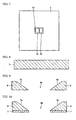
- Fig. 2 is a perspective drawing of the semiconductor device shown in Fig. 1A.
- Fig. 3 is a perspective drawing of the semiconductor light-emitting element shown in Fig. 1A.
- a semiconductor device 100 includes: a light-emitting element mounting member 200; and a semiconductor light-emitting element 1 mounted on an element mounting surface 2a.
- the semiconductor light-emitting element 1 includes a main surface 1a facing the element mounting surface 2a.
- the main surface 1a is formed as a rectangle including a longer first side 11 and a shorter second side 12.
- a substrate 2 includes a bottom surface 2b opposite from the element mounting surface 2a.
- a distance H from the bottom surface 2b to the element mounting surface 2a and a length L of the first side 11 have a ratio H/L of at least 0.3.
- the light-emitting element mounting member 200 includes the substrate 2 and a reflective surface 6a and is equipped with a reflective member 6 and a metal layer 13.
- the substrate 2 includes: the mounting surface 2a for mounting a semiconductor light-emitting element 1; and first and second conductor regions 21, 22 disposed on the element mounting surface 2a and connected to the semiconductor light-emitting element 1.
- the reflective surface 6a defines an inner space 6b which houses the semiconductor light-emitting element 1.
- the reflective member 6 is disposed on the element mounting surface 2a and contains metal.
- the metal layer 13 is disposed on the reflective surface 6a.
- the reflective surface 6a is sloped relative to the element mounting surface 2a so that the diameter of the inner space 6b is larger away from the element mounting surface 2a.
- the light-emitting element 200 is further equipped with a bonding layer 9 that joins the element mounting surface 2a and the reflective member 6.
- the bonding layer 9 has a temperature rating of at least 300 deg C, and the bonding layer 9 melts at a temperature of no more than 700 deg C to bond the element mounting surface 2a and the reflective member 6.
- the substrate 2 is insulative and is formed with first and second through-holes 2h, 2i.
- the first conductor region 21 is disposed on the first through-hole 2h
- the second conductor region 22 is disposed on the second through-hole 2i.
- the minimum pattern width and the minimum distance between patterns for the metal film formed on the element mounting surface at the first and/or second conductor regions 21, 22 are kept within the range of at least 5 microns and less than 10 microns. This allows flip-chip light-emitting elements and the like to be mounted.
- a range of at least 10 microns and less than 50 microns is preferable.
- smaller distances are preferable between patterns in the first and second conductor regions 21, 22 as long as bad connections are avoided. The reason for this is that reflection efficiency improves when a larger area is metallized. At less than 5 microns, bad connections tend to form.
- Electrode layers 1b and 1f are disposed on the main surface 1a of the semiconductor light-emitting element 1 and are connected to the first and second conductor regions 21, 22.
- the area of the main surface 1a is at least 1 mm 2 .
- the substrate 2 is electrically insulative and formed from a material with good heat conductivity.
- the material can be selected based on the usage environment.
- the material can be ceramics having as the main component aluminum nitride (AlN), silicon nitride (Si 3 N 4 ), aluminum oxide (Al 2 O 3 ), boron nitride (BN), silicon carbide (SiC), or the like.
- AlN aluminum nitride
- Si 3 N 4 silicon nitride
- BN aluminum oxide
- SiC silicon carbide
- a material that has as the main component electrically insulative silicon (Si), or a composite material or a combination of the above can be used.
- the substrate 2 acts as a heat sink that dissipates heat.
- higher heat conduction is preferable, and a heat conduction rate of at least 140 W/m ⁇ K would be preferable, with a rate of at least 170 W/m ⁇ K being more preferable.
- the thermal expansion coefficient linear expansivity
- Au films 3a, 3b, 3 are formed on the element mounting surface 2a.
- the Au film 3 serves to improve the bond between the bonding layer 9 and the substrate 2.
- the Au film 3 is formed from a material that improves the bond between the bonding layer 9 and the substrate 2.
- the Au film 3 is used since, in this embodiment, nitride aluminum, a ceramic, is used for the substrate 2, and Au-Ge is used for the bonding layer 9. If the material used in the bonding layer is changed, then it would be possible to form the Au films 3, 3a, 3b as layers having aluminum as the main component or silver as the main component.
- the Au films 3, 3a, 3b are formed by plating, vapor deposition, or the like. It would also be possible to interpose an intermediate layer to improve the bond, e.g., a titanium layer or a platinum layer, between the Au films 3, 3a, 3b and the element mounting surface 2a.
- Examples of intermediate layers disposed between the element mounting surface 2a and the Au films 3, 3a, 3b include Ni, Ni-Cr, Ni-P, Ni-B, and NiCo. These can be formed by plating, vapor deposition, or the like. If vapor deposition is to be performed, materials such as Ti, V, Cr, Ni, NiCr alloy, Zr, Nb, Ta can be used. It would also be possible to stack plated layers and/or vapor deposition layers. It would be preferable for the thickness of the intermediate layer to be at least 0.01 mm and no more than 5 mm, and more preferably at least 0.1 mm and no more than 1 mm.
- an intermediate layer e.g., formed from a Ti/Pt layered film, between the substrate 2 and the Au films 3, 3a, 3b.
- the film containing Ti in this stacked film serves as a bonding layer to improve bonding with the substrate 2 and is formed so that it comes into contact with the upper surface of the substrate 2.
- the material for the bonding layer does not need to be titanium and can be, for example, vanadium (V), chrome (Cr), nickel-chrome alloy (NiCr), zirconium (Zr), niobium (Nb), tantalum (Ta), or a compound of thereof.
- the platinum (Pt) film in the Ti/Pt stacked film is a diffusion barrier layer and is formed on the upper surface of the Ti film.
- the material does not need to be platinum (Pt), and can be palladium (Pd), nickel-chrome alloy (NiCr), nickel (Ni), molybdenum (Mo), copper (Cu), or the like.
- the Ti/Pt stacked film and the Au films described above are collectively referred to as a metallized film.
- the metallized film can be formed using conventional film-forming methods described above. For example, vapor deposition, sputtering, or plating can be used.
- the patterning of the Ti/Pt stacked film and the Au films can be performed using metal masking, dry etching, chemical etching, or lift-off involving photolithography. These methods are suitable when forming fine patterns restricted to less than 100 microns or less than 50 microns.
- the thickness of the titanium (Ti) film in the Ti/Pt stacked film prefferably be at least 0.01 mm and no more than 1.0 mm, and the thickness of the platinum (Pt) film to be at least 0.01 mm and no more than 1.5 mm.
- the thickness of the substrate 2, i.e., the distance H from the bottom surface 2b to the element mounting surface 2a, can be set up according to the dimensions of the semiconductor element 1, but, as an example, the distance H can be set to at least 0.3 mm and no more than 10 mm.
- the semiconductor light-emitting element 1 is disposed so that it comes into contact with the Au films 3a, 3b.
- the semiconductor light-emitting element 1 can be formed from a group II-VI compound semiconductor light-emitting element or a group III-V compound semiconductor light-emitting element.
- the group II elements here include zinc (Zn) and cadmium (Cd).
- the group III elements include boron (B), aluminum (Al), gallium (Ga), and indium (In).
- the group V elements include nitrogen (N), phosphorous (P), arsenic (As), and antimony (Sb).
- the group VI elements include oxygen (O), sulfur (S), selenium (Se), and tellurium (Te).
- the semiconductor light-emitting element 1 can be formed as a compound semiconductor that is GaAs-based, InP-based, GaN-based, or the like.
- Through-holes 2h, 2i are formed as via holes on the substrate 2.
- the conductors used to fill the through-holes 2h, 2i form the first and second conductor regions 21, 22.
- the main component for the conductor (via fill) is preferably a metal with a high melting point, particularly tungsten (W) or molybdenum (Mo). It would also be possible to further include a transitional metal such as titanium (Ti) or a glass component or substrate material (e.g., aluminum nitride (AlN)). Also, the through-holes 2h, 2i do not need to be filled with conductor if the inner surfaces thereof are metallized by plating or the like.
- the surface roughness of the element mounting surface 2a is preferably no more than 1 micron Ra and more preferably no more than 0.1 micron Ra.
- the flatness is preferably no more than 5 microns and more preferably 1 micron. If the Ra exceeds 1 micron or the flatness exceeds 5 microns, gaps tend to form between the semiconductor light-emitting element 1 and the substrate 2 during bonding, leading to reduced cooling of the semiconductor light-emitting element.
- Surface roughness Ra and the flatness are defined according to JIS standards (JIS B0601 and JIS B0621, respectively).
- the compound semiconductors described above are examples of materials for the semiconductor light-emitting element 1 of the present invention, but it would also be possible to stack these layers or bulks on a substrate such as a sapphire substrate.
- the light-emitting section can be at either the top surface or the bottom surface.
- the light-emitting layer 1c is disposed on the substrate side. Since the light-emitting layer 1c, which is the heat-generating section, is disposed closer to the substrate, heat dissipation for the semiconductor element can be improved.
- a metallized layer e.g., an electrode layer and insulation layer formed from silicon oxide film (SiO 2 ) can be formed on the surface of the semiconductor light-emitting element 1 disposed on the substrate 2. It would be preferable for the thickness of the gold (Au) serving as the electrode layer to be at least 0.1 microns and no more than 10 microns.
- the semiconductor light-emitting element 1 includes: a base unit 1e formed from sapphire or the like; a semiconductor layer 1d in contact with the base unit 1e; a light-emitting layer 1c in contact with a section of the semiconductor layer 1d; a semiconductor layer 1g in contact with the light-emitting layer 1c; an electrode layer 1b in contact with the semiconductor layer 1g; and an electrode layer 1f in contact with the semiconductor layer 1d.
- the structure of the semiconductor light-emitting element 1 is not restricted to what is shown in Fig. 1A.
- electrodes are present on both the front and back of the semiconductor light-emitting element 1, and the electrode layer 1b is connected by an Au bonding line 71 to the Au film 3b.
- Fig. 1B only the first conductor region is directly bonded to the semiconductor light-emitting element 1.
- the first side 11 is the long side and the second side 12 is the short side.
- the first side 11 is the short side and the second side 12 be the long side.
- the main surface of the semiconductor light-emitting element is rectangular, so the long side corresponds to the length L along the direction of the long side.
- the first side 11 extends roughly perpendicular to the direction in which the light-emitting layer 1c extends.
- the second side 12 extends roughly parallel to the light-emitting layer 1c.
- the first side 11 and the second side 12 can be roughly the same length.
- the first side 11 and the second side 12 are roughly the same length, the first side 11 is treated as the long side.
- the main surface 1a is not rectangular, e.g., if the corners are rounded, the long side is defined based on an approximation of the main surface 1a to a rectangle.
- the opposite surface will generally be roughly the same shape, but this does not need to be the case.
- the main surface can be non-rectangular.
- the length along the direction of the long side of the main surface of the semiconductor element of the present invention is measured from the outline of the image projected in a direction perpendicular to the main surface.
- Fig. 3B1 through Fig. 3B5 are examples of this, and the indicated lengths L are the lengths along the direction of the long side.
- the shape is a circle or a square, the length would be the diameter or one of the sides, respectively. If the shape is an ellipse, the length of the major axis is used.
- the long-side length L of the semiconductor light-emitting element 1 corresponds to the length of the first side 11. It would be preferable for the ratio H/L between this length and the distance H from the bottom surface 2b to the element mounting surface 2a to be at least 0.3. It would be more preferable for the ratio H/L to be at least 4.5 and no more than 1.5. It would be even more preferable for the ratio H/L to be at least 0.5 and no more than 1.25.
- the reflective member 6 is disposed so that it surrounds the semiconductor light-emitting element 1.
- a material having a thermal coefficient close to the aluminum nitride forming the substrate 2 is used.
- the reflective member can have a thermal expansion coefficient of at least 3 x 10 -6 /K and no more than 7 x 10 -6 /K. It would be preferable for the reflective member 6 to have a thermal expansion coefficient of at least 4 x 10 -6 /K and no more than 6 x 10 -6 /K.
- the reflective member 6 is formed from a Ni-Co-Fe alloy, with the main components being Ni with a proportion of 29% by mass, Co with a proportion of 18% by mass, and Fe with a proportion of 53% by mass.
- the reflective surface 6a is a tapered, sloped surface disposed on the reflective member 6.
- the reflective surface 6a forms an angle relative to the element mounting surface 2a preferably in the range of 30 deg to 70 deg and more preferably in the range of 40 deg to 60 deg.
- a plating layer 7 formed from Ni/Au is disposed on the reflective member 6. This plating layer is used when an Au-based solder (Au-Ge) is to be used for the bonding layer 9 and serves to increase the bonding strength between the bonding layer 9 and the reflective member 6.
- Au-Ge Au-based solder
- a plating layer 7 can also be disposed along the entire perimeter of the reflective member 6.
- a metal layer 13 is formed to cover the surface of the reflective member 6.
- the metal layer 13 is formed by plating or vapor deposition and serves to let out light emitted from the semiconductor light-emitting element 1.
- the reflective surface 6a defines the inner space 6b, and the inner space 6b forms a cone shape.
- the circular cone shape shown in Fig. 2 is an example.
- the inner space 6b can be formed as an angular cone shape such as a four-side cone or a triangular cone.
- the reflective surface 6a can be formed as a curved surface such as a parabolic surface.
- Fig. 4 is a flow chart illustrating the method for making the semiconductor device shown in Fig. 1.
- Fig. 5 through Fig. 12 are figures for the purpose of describing the method for making the semiconductor device shown in Fig. 3.
- a substrate is produced first (step 201). Since the length and width of this type of substrate 2 is very small, on the order of a few millimeters, a substrate base with length and width of approximately 50 mm is produced and the through holes 2h, 2i are formed on the substrate base material. The first and second conductive regions 21, 22 are formed on the through-holes 2h, 2i. Then, the substrate base is finely cut to a predetermined size.
- the size of the substrate base in this method can be, for example, 50 mm in width, 50 mm in length, and 0.3 mm in thickness.
- the sintered aluminum nitride, which is the substrate material is made using a standard method. The cutting and splitting the substrate base to a predetermined size can, for example, be performed after bonding (step 206) or at another step.
- the surface of the substrate from the second step is abraded (step 202).
- the surface roughness of the abraded substrate surface is preferably an Ra of no more than 1.0 microns and more preferably no more than 0.1 microns.
- the abrading can be performed using a standard method such as with a grinder, sand blasting, sand paper, or other methods using abrasive particles.
- an Au film is formed using plating or vapor deposition on the element mounting surface 2a and the bottom surface 2b of the substrate 2 (step 203). More specifically, in the case of this embodiment, for example, Ti/Pt is first vaporized to serve as a backing layer and an Au film is vaporized on this.
- the vapor deposition method can, for example, involve photolithography, where resist film is formed on the sections of the substrate outside of the regions at which the films are to be formed, with the layers being formed on the resist film and the substrate.
- the Ti film serving as the bonding layer is vaporized, followed by the Pt film serving as the diffusion barrier layer, and then finally the Au film, which is the electrode layer, is vaporized as the outermost layer. Then, lift-off of the resist is performed. More specifically, the resist film formed in the above step is removed along with the films from the bonding layer, the diffusion barrier layer and the electrode layer using a resist removal fluid. As a result, as shown in Fig. 6 and Fig. 7, the Au films 3, 3a, 3b, 3c, 3d are formed in predetermined patterns on the substrate. The Au films 3a, 3b are formed at the central section of the substrate, and the Au film 3 is formed to surround these films.
- patterns with pattern dimensions of no more than 100 microns can be formed, and it would also be possible to form patterns with dimensions of no more than 50 microns.
- the dimensions refer to the smallest distance between patterns, the pattern widths, and the like.
- peripheral members that require high-precision dimensions such as flip-chip semiconductor light-emitting elements.
- the reflective member 6 is prepared, as shown in Fig. 4 and Fig. 8. As described above, the reflective member 6 is formed from a material with a thermal expansion coefficient close to that of aluminum nitride, e.g., an alloy with low thermal expansion formed from Ni-Co-Fe.
- the reflective surface 6a is formed by processing the reflective member 6 (step 204).
- the reflective surface 6a expands outward, forming an angle (e.g., 45 deg) relative to the widest surface of the reflective member 6.
- a plating layer 7 is formed on the reflective member 6 (step 205).
- the plating layer 7 is an Ni/Au stack. Forming the plating layer 7 along the entire perimeter of the reflective member 6 is acceptable.
- the bonding layer 9 can be solder, sealing/coating glass, heat-resistant adhesive, or the like, and connects the reflective member and the substrate at a temperature that does not exceed the temperature tolerance of the metallized patterns.
- solder is Au-Ge solder.
- the use of solder is preferable due to bonding strength and its Pb-free content.
- heat-resistant adhesives include inorganic adhesives and resin adhesives.
- solder is Ag-based solder.
- inorganic adhesives include glass and ceramic adhesives.
- resin adhesives include polyimide resins, polyamide-imide resin, epoxy resin, acrylic epoxy resin, and liquid-crystal polymer resin.
- the metal layer 13 is formed, e.g., through plating or vapor deposition (step 207).
- the metal layer 13 serves to let out light emitted from the semiconductor light-emitting element, and it would be preferable for the outermost layer to be formed from a material with a high reflectivity, e.g., Ag, Al, or metals with these elements as main components. If the reflectivity of the reflective member 6 itself is high, the metal layer 13 can be eliminated. Also, in some cases, the metal layer 13 on the Au film 3a, 3b where the element is mounted may be eliminated in order to improve the reliability of the bond with the semiconductor element.
- the semiconductor light-emitting element is mounted (step 208).
- the mounting is performed in this case using a flip-chip connection, with the light-emitting layer 1c disposed toward the substrate 2.
- the heat generated by the light-emitting layer 1c is transferred immediately to the substrate 2, providing good heat dissipation.
- members used in the connection include Sn-based solder such as Sn, Au-Sn, Ag-Sn, and Pb-Sn solder, as well as bumps formed from Au or any of these solders.
- the reflective member 6 contains metal.
- the metal layer 13 can be formed directly on the surface of the reflective member 6. Also, if the reflective member 6 is to be processed in the step shown in Fig. 9, the processing is made easy and production costs can be reduced.
- Fig. 13 is a cross-section drawing of a light-emitting element mounting member and a semiconductor device that uses the same according to a second embodiment of the present invention.
- metal films 4, 4a, 4b are formed on the element mounting surface 2a, and the metal films 4, 4a, 4b are formed from Ag or Al.
- the metal layer 13 formed only on the reflective member 6.
- the reflective member 6 was attached to the element mounting surface 2a of the substrate 2 formed from aluminum nitride, interposed by the bonding layer 9.
- the reflective member 6 is an Ni-Co-Fe alloy with an Ni proportion of 29% by mass, a Co proportion of 18% by mass, and an Fe proportion of 53% by mass. Also, the dimensions of the reflective member 6 were set to 5 mm x 5 mm x 1 mm (height x width x thickness).
- the bonding layer was left in an atmosphere with a temperature of 300 deg C for one minute and for 24 hours at the same temperature.
- the samples in which the bonding layer 9 did not melt again or soften and for which the drop in bonding strength, as measured according to the method indicated in Fig. 1, was less than 10% was evaluated as good and a circle was entered in the "Heat resistance” column.
- the results from 300 deg C for one minute was entered in the "Heat resistance 1" column and the result from the same temperature at 24 hours was entered in the "Heat resistance 2" column.
- an "X" was entered in the "Heat resistance” column.
- the drop in bonding strength was calculated using the formula ((A1-A2)/A1), where A1 is the initial strength and A2 is the strength at room temperature after being heated at 300 deg C.
- a bonding temperature of at least 300 deg C refers to when the bonding layer 9 does not re-melt or soften even after the bonding layer is kept in a 300 deg C atmosphere for 1 minute and that has a bonding strength drop of less than 10% when measured according to the method indicated in Fig. 1.
- the drop in bonding strength is calculated using the formula ((A1-A2)/A1), where A1 is the initial strength (bonding strength before the layer is kept in a temperature of 300 deg C) and A2 is the strength at room temperature after being kept in a 300 deg C atmosphere for 1 minute.
- the deterioration of the electrode metallization patterns was measured as well. More specifically, visual inspections and thickness measurements were performed on the electrode metallized patterns after the light-emitting element mounting member 200 was kept in a 300 deg C atmosphere for 24 hours. Samples in which deterioration such as discoloration did not take place for Au films 3, 3a, 3b were indicated as circles. If there was discoloration in the Au films 3, 3a, 3b or if the thickness of the Au films 3, 3a, 3b decreased, an "X" was indicated.
- a light-emitting element mounting member and a semiconductor device that uses the same that can be easily processed and that has superior heat dissipation properties can be provided.
Landscapes
- Engineering & Computer Science (AREA)
- Microelectronics & Electronic Packaging (AREA)
- Manufacturing & Machinery (AREA)
- Computer Hardware Design (AREA)
- Power Engineering (AREA)
- Led Device Packages (AREA)
Applications Claiming Priority (3)
| Application Number | Priority Date | Filing Date | Title |
|---|---|---|---|
| JP2003074036 | 2003-03-18 | ||
| JP2003074036 | 2003-03-18 | ||
| PCT/JP2004/003443 WO2004084319A1 (fr) | 2003-03-18 | 2004-03-15 | Element de montage pour un element electroluminescent, et dispositif a semi-conducteur utilisant celui-ci |
Publications (3)
| Publication Number | Publication Date |
|---|---|
| EP1605524A1 true EP1605524A1 (fr) | 2005-12-14 |
| EP1605524A4 EP1605524A4 (fr) | 2009-01-07 |
| EP1605524B1 EP1605524B1 (fr) | 2010-06-30 |
Family
ID=33027803
Family Applications (1)
| Application Number | Title | Priority Date | Filing Date |
|---|---|---|---|
| EP04720727A Expired - Fee Related EP1605524B1 (fr) | 2003-03-18 | 2004-03-15 | Element de montage pour un element electroluminescent, et dispositif a semi-conducteur utilisant celui-ci |
Country Status (7)
| Country | Link |
|---|---|
| US (1) | US7518155B2 (fr) |
| EP (1) | EP1605524B1 (fr) |
| JP (1) | JP3918858B2 (fr) |
| KR (1) | KR101045507B1 (fr) |
| CN (1) | CN100459188C (fr) |
| DE (1) | DE602004027890D1 (fr) |
| WO (1) | WO2004084319A1 (fr) |
Cited By (8)
| Publication number | Priority date | Publication date | Assignee | Title |
|---|---|---|---|---|
| EP1744374A1 (fr) * | 2004-04-12 | 2007-01-17 | Sumitomo Electric Industries, Ltd. | Support de montage d" élément électroluminescent semi-conducteur, et dispositif électroélectroluminescent semi-conducteur utilisant celui-ci |
| DE102005059524A1 (de) * | 2005-09-30 | 2007-04-05 | Osram Opto Semiconductors Gmbh | Gehäuse für ein elektromagnetische Strahlung emittierendes optoelektronisches Bauelement, Bauelement und Verfahren zum Herstellen eines Gehäuses oder eines Bauelements |
| WO2008098832A1 (fr) * | 2007-02-15 | 2008-08-21 | Hymite A/S | Procédé de fabrication pour boîtier muni d'un dispositif émettant de la lumière sur une embase |
| CN101432899A (zh) * | 2006-04-28 | 2009-05-13 | 岛根县 | 半导体发光组件及其制造方法、半导体发光装置 |
| EP1806789A4 (fr) * | 2004-10-04 | 2009-09-02 | Toshiba Kk | Dispositif electroluminescent, materiel d'eclairage ou dispositif d'affichage a cristaux liquides mettant en oeuvre ce dispositif |
| EP1953818A4 (fr) * | 2005-11-24 | 2010-11-10 | Sanyo Electric Co | Carte de montage de composants electroniques et procede de fabrication d' une telle carte |
| EP2365549A1 (fr) * | 2010-03-12 | 2011-09-14 | Asahi Glass Company, Limited | Dispositif électroluminescent |
| EP2387082A3 (fr) * | 2006-04-21 | 2014-08-06 | Tridonic Jennersdorf GmbH | Plateforme de DEL comportant une puce DEL sur une membrane |
Families Citing this family (89)
| Publication number | Priority date | Publication date | Assignee | Title |
|---|---|---|---|---|
| US7919787B2 (en) | 2003-06-27 | 2011-04-05 | Avago Technologies Ecbu Ip (Singapore) Pte. Ltd. | Semiconductor device with a light emitting semiconductor die |
| DE102004014207A1 (de) * | 2004-03-23 | 2005-10-13 | Osram Opto Semiconductors Gmbh | Optoelektronisches Bauteil mit mehrteiligem Gehäusekörper |
| JP4675906B2 (ja) * | 2004-10-27 | 2011-04-27 | 京セラ株式会社 | 発光素子搭載用基板、発光素子収納用パッケージ、発光装置および照明装置 |
| JP2006156747A (ja) * | 2004-11-30 | 2006-06-15 | Ngk Spark Plug Co Ltd | 配線基板 |
| KR100867515B1 (ko) * | 2004-12-06 | 2008-11-07 | 삼성전기주식회사 | 발광소자 패키지 |
| JP4831958B2 (ja) * | 2004-12-06 | 2011-12-07 | スタンレー電気株式会社 | 表面実装型led |
| KR100624449B1 (ko) * | 2004-12-08 | 2006-09-18 | 삼성전기주식회사 | 요철 구조를 포함하는 발광 소자 및 그 제조 방법 |
| US20070145386A1 (en) * | 2004-12-08 | 2007-06-28 | Samsung Electro-Mechanics Co., Ltd. | Semiconductor light emitting device and method of manufacturing the same |
| TWI239670B (en) * | 2004-12-29 | 2005-09-11 | Ind Tech Res Inst | Package structure of light emitting diode and its manufacture method |
| KR100587016B1 (ko) * | 2004-12-30 | 2006-06-08 | 삼성전기주식회사 | 식각 정지막을 갖는 발광다이오드 패키지 및 그 제조 방법 |
| JP2006197278A (ja) * | 2005-01-14 | 2006-07-27 | Seiko Instruments Inc | 表面実装型圧電振動子、発振器、及び電子機器 |
| US7655997B2 (en) * | 2005-01-26 | 2010-02-02 | Harvatek Corporation | Wafer level electro-optical semiconductor manufacture fabrication mechanism and a method for the same |
| US8029152B2 (en) * | 2005-03-24 | 2011-10-04 | Kyocera Corporation | Package for light-emitting device, light-emitting apparatus, and illuminating apparatus |
| EP1732132B1 (fr) * | 2005-06-06 | 2009-12-23 | Ching-Fu Tsou | Procédé pour l'encapsulation d'une structure modulaire de diodes électroluminescentes du type réseau |
| JP5073179B2 (ja) * | 2005-06-09 | 2012-11-14 | 株式会社住友金属エレクトロデバイス | 発光素子収納用窒化アルミニウム焼結体 |
| JP4761848B2 (ja) * | 2005-06-22 | 2011-08-31 | 株式会社東芝 | 半導体発光装置 |
| JP4668722B2 (ja) * | 2005-08-02 | 2011-04-13 | 日立協和エンジニアリング株式会社 | サブマウント及びその製造方法 |
| EP1911389A4 (fr) * | 2005-08-05 | 2009-12-16 | Olympus Medical Systems Corp | Unité électroluminescente |
| KR20080037734A (ko) * | 2005-08-23 | 2008-04-30 | 가부시끼가이샤 도시바 | 발광 장치와 그를 이용한 백 라이트 및 액정 표시 장치 |
| KR101241650B1 (ko) | 2005-10-19 | 2013-03-08 | 엘지이노텍 주식회사 | 엘이디 패키지 |
| US7719099B2 (en) * | 2005-10-21 | 2010-05-18 | Advanced Optoelectronic Technology Inc. | Package structure for solid-state lighting devices and method of fabricating the same |
| JP4238864B2 (ja) * | 2005-11-02 | 2009-03-18 | ソニー株式会社 | 半導体装置および半導体装置の製造方法 |
| KR101231420B1 (ko) * | 2006-01-04 | 2013-02-07 | 엘지이노텍 주식회사 | 발광 다이오드 장치 |
| US7928462B2 (en) * | 2006-02-16 | 2011-04-19 | Lg Electronics Inc. | Light emitting device having vertical structure, package thereof and method for manufacturing the same |
| JP5110804B2 (ja) * | 2006-03-24 | 2012-12-26 | 日本エレクトロプレイテイング・エンジニヤース株式会社 | Ledの製造方法 |
| JP4981342B2 (ja) * | 2006-04-04 | 2012-07-18 | 日立協和エンジニアリング株式会社 | サブマウントおよびその製造方法 |
| JP2007294587A (ja) * | 2006-04-24 | 2007-11-08 | Ngk Spark Plug Co Ltd | 発光素子収納用パッケージ |
| JP4854738B2 (ja) * | 2006-06-15 | 2012-01-18 | 三洋電機株式会社 | 電子部品 |
| KR100759016B1 (ko) * | 2006-06-30 | 2007-09-17 | 서울반도체 주식회사 | 발광 다이오드 |
| JP2008016565A (ja) * | 2006-07-04 | 2008-01-24 | Shinko Electric Ind Co Ltd | 発光素子収容体及びその製造方法、及び発光装置 |
| KR100854328B1 (ko) * | 2006-07-07 | 2008-08-28 | 엘지전자 주식회사 | 발광 소자 패키지 및 그 제조방법 |
| KR100772649B1 (ko) * | 2006-07-21 | 2007-11-02 | (주) 아모센스 | 반도체 패키지의 제조방법 및 그 제조방법에 의해 제조된반도체 패키지 |
| JP2008041811A (ja) * | 2006-08-03 | 2008-02-21 | Ngk Spark Plug Co Ltd | 配線基板および多数個取り配線基板ならびにその製造方法 |
| JP4846505B2 (ja) * | 2006-10-10 | 2011-12-28 | 株式会社フジクラ | 発光装置およびその製造方法 |
| JP4963950B2 (ja) * | 2006-12-12 | 2012-06-27 | スタンレー電気株式会社 | 半導体発光装置およびその製造方法 |
| JP4836769B2 (ja) * | 2006-12-18 | 2011-12-14 | スタンレー電気株式会社 | 半導体発光装置およびその製造方法 |
| JP2008166440A (ja) * | 2006-12-27 | 2008-07-17 | Spansion Llc | 半導体装置 |
| KR100802393B1 (ko) * | 2007-02-15 | 2008-02-13 | 삼성전기주식회사 | 패키지 기판 및 그 제조방법 |
| JP5106094B2 (ja) * | 2007-02-22 | 2012-12-26 | シャープ株式会社 | 表面実装型発光ダイオードおよびその製造方法 |
| US8436371B2 (en) * | 2007-05-24 | 2013-05-07 | Cree, Inc. | Microscale optoelectronic device packages |
| JP5075493B2 (ja) * | 2007-06-13 | 2012-11-21 | 株式会社住友金属エレクトロデバイス | 発光素子収納用パッケージ及びその製造方法及びそれを用いた発光装置 |
| JP2009033088A (ja) * | 2007-06-29 | 2009-02-12 | Sharp Corp | 半導体発光装置、その製造方法およびそれを用いたled照明装置 |
| US20090032829A1 (en) * | 2007-07-30 | 2009-02-05 | Tong Fatt Chew | LED Light Source with Increased Thermal Conductivity |
| JP2009049408A (ja) * | 2007-08-14 | 2009-03-05 | Avago Technologies Ecbu Ip (Singapore) Pte Ltd | 発光半導体ダイを有する半導体デバイス |
| US8212271B2 (en) * | 2007-10-11 | 2012-07-03 | Hitachi Chemical Co., Ltd. | Substrate for mounting an optical semiconductor element, manufacturing method thereof, an optical semiconductor device, and manufacturing method thereof |
| KR100934171B1 (ko) * | 2007-10-31 | 2009-12-29 | 주식회사 케이아이자이맥스 | 방열 구조체 및 이의 제조 방법 |
| TWI408829B (zh) * | 2007-11-08 | 2013-09-11 | Chipbond Technology Corp | 發光二極體次黏著基板封裝方法及其封裝構造 |
| US20090152568A1 (en) * | 2007-12-14 | 2009-06-18 | International Semiconductor Technology Ltd. | Method for packaging submount adhering light emitting diode and package structure thereof |
| JP2009158759A (ja) * | 2007-12-27 | 2009-07-16 | Internatl Semiconductor Technology Ltd | Ledの実装方法及びそのパッケージ |
| JP5064278B2 (ja) * | 2008-03-25 | 2012-10-31 | 日東電工株式会社 | 光半導体素子封止用樹脂シートおよび光半導体装置 |
| KR100999699B1 (ko) * | 2008-09-01 | 2010-12-08 | 엘지이노텍 주식회사 | 발광 소자 패키지 |
| CN101740678A (zh) * | 2008-11-10 | 2010-06-16 | 富士迈半导体精密工业(上海)有限公司 | 固态发光元件及光源模组 |
| KR101064026B1 (ko) * | 2009-02-17 | 2011-09-08 | 엘지이노텍 주식회사 | 발광 디바이스 패키지 및 그 제조방법 |
| US20120061695A1 (en) * | 2009-03-24 | 2012-03-15 | Kang Kim | Light-emitting diode package |
| US8110839B2 (en) * | 2009-07-13 | 2012-02-07 | Luxingtek, Ltd. | Lighting device, display, and method for manufacturing the same |
| WO2011043441A1 (fr) * | 2009-10-07 | 2011-04-14 | 京セラ株式会社 | Dispositif électroluminescent |
| CN102044600A (zh) * | 2009-10-15 | 2011-05-04 | 展晶科技(深圳)有限公司 | 发光二极管封装结构及其制备方法 |
| KR101056903B1 (ko) * | 2009-12-17 | 2011-08-12 | 주식회사 두산 | 발광소자 패키지용 기판 및 이를 이용한 발광소자 패키지 |
| CN102130269B (zh) * | 2010-01-19 | 2013-03-27 | 富士迈半导体精密工业(上海)有限公司 | 固态发光元件及光源模组 |
| TW201126765A (en) * | 2010-01-29 | 2011-08-01 | Advanced Optoelectronic Tech | Package structure of compound semiconductor and manufacturing method thereof |
| KR101277201B1 (ko) * | 2010-04-23 | 2013-06-20 | 주식회사 코스텍시스 | 기판 유닛 및 이를 이용한 발광 다이오드 패키지 |
| KR101028329B1 (ko) * | 2010-04-28 | 2011-04-12 | 엘지이노텍 주식회사 | 발광 소자 패키지 및 그 제조방법 |
| DE102010045403A1 (de) | 2010-09-15 | 2012-03-15 | Osram Opto Semiconductors Gmbh | Optoelektronisches Bauelement |
| JP5725029B2 (ja) * | 2010-09-17 | 2015-05-27 | 旭硝子株式会社 | 発光素子搭載用基板および発光装置 |
| US8941137B2 (en) * | 2011-03-06 | 2015-01-27 | Mordehai MARGALIT | Light emitting diode package and method of manufacture |
| US8901578B2 (en) | 2011-05-10 | 2014-12-02 | Rohm Co., Ltd. | LED module having LED chips as light source |
| KR101294488B1 (ko) * | 2011-11-14 | 2013-08-07 | 엘지이노텍 주식회사 | 발광장치 |
| WO2013073897A2 (fr) * | 2011-11-17 | 2013-05-23 | 주식회사 루멘스 | Boîtier de dispositif électroluminescent et rétroéclairage le comprenant |
| TWI443877B (zh) * | 2011-12-15 | 2014-07-01 | Genesis Photonics Inc | 反射元件以及發光二極體封裝裝置 |
| KR20130096094A (ko) * | 2012-02-21 | 2013-08-29 | 엘지이노텍 주식회사 | 발광소자 패키지, 발광 소자 패키지 제조방법 및 이를 구비한 조명 시스템 |
| JP6293995B2 (ja) * | 2012-03-23 | 2018-03-14 | 新光電気工業株式会社 | 発光素子搭載用パッケージ及びその製造方法、並びに発光素子パッケージ |
| US9735198B2 (en) | 2012-03-30 | 2017-08-15 | Cree, Inc. | Substrate based light emitter devices, components, and related methods |
| KR101292197B1 (ko) * | 2012-04-10 | 2013-08-01 | 대덕전자 주식회사 | 발광다이오드 실장 회로기판에 반사판을 제조하는 방법 |
| KR20140041243A (ko) * | 2012-09-27 | 2014-04-04 | 삼성전자주식회사 | 발광소자 패키지 및 패키지 기판 |
| CN103441210B (zh) * | 2013-06-08 | 2017-07-28 | 深圳市环基实业有限公司 | 一种led封装结构和led封装方法 |
| US20140367816A1 (en) * | 2013-06-12 | 2014-12-18 | Avago Technologies General Ip (Singapore) Pte.Ltd. | Photodetector device having light-collecting optical microstructure |
| WO2015008243A1 (fr) * | 2013-07-19 | 2015-01-22 | Koninklijke Philips N.V. | Del de pc à élément optique et sans substrat de support |
| JP6244130B2 (ja) | 2013-07-26 | 2017-12-06 | 新光電気工業株式会社 | 発光素子搭載用パッケージ及び発光素子パッケージ |
| KR102122361B1 (ko) * | 2013-12-27 | 2020-06-15 | 삼성전자주식회사 | 플립칩 엘이디 패키지 기판 및 플립칩 엘이디 패키지 구조 |
| CN107251245A (zh) * | 2015-02-25 | 2017-10-13 | 京瓷株式会社 | 发光元件搭载用封装体、发光装置以及发光模块 |
| DE102015103840A1 (de) * | 2015-03-16 | 2016-09-22 | Osram Opto Semiconductors Gmbh | Elektromagnetische Strahlung emittierende Baugruppe |
| DE102015208704A1 (de) * | 2015-05-11 | 2016-11-17 | Osram Opto Semiconductors Gmbh | Optoelektronisches Bauteil |
| CN105790071A (zh) * | 2016-03-22 | 2016-07-20 | 西安炬光科技股份有限公司 | 一种高功率半导体激光器及其制备方法 |
| JP6294419B2 (ja) * | 2016-09-01 | 2018-03-14 | 日機装株式会社 | 光半導体装置および光半導体装置の製造方法 |
| JP7408266B2 (ja) * | 2017-06-14 | 2024-01-05 | 日亜化学工業株式会社 | 光源装置 |
| US10672957B2 (en) * | 2017-07-19 | 2020-06-02 | Cree, Inc. | LED apparatuses and methods for high lumen output density |
| JP6970336B2 (ja) * | 2017-08-04 | 2021-11-24 | 日亜化学工業株式会社 | 光源装置 |
| JP7007560B2 (ja) * | 2017-09-28 | 2022-01-24 | 日亜化学工業株式会社 | 光源装置 |
| EP3736839A1 (fr) * | 2019-05-06 | 2020-11-11 | AT & S Austria Technologie & Systemtechnik Aktiengesellschaft | Support de composant comprenant un empilement d'aimant intégré |
Citations (1)
| Publication number | Priority date | Publication date | Assignee | Title |
|---|---|---|---|---|
| JP2003008074A (ja) * | 2001-06-26 | 2003-01-10 | Nichia Chem Ind Ltd | 表面実装型発光装置及びその製造方法 |
Family Cites Families (21)
| Publication number | Priority date | Publication date | Assignee | Title |
|---|---|---|---|---|
| JPS60179190A (ja) | 1984-02-27 | 1985-09-13 | Ebara Infilco Co Ltd | 脱リン装置 |
| JPH0388422U (fr) * | 1989-12-20 | 1991-09-10 | ||
| US5760479A (en) * | 1996-02-29 | 1998-06-02 | Texas Instruments Incorporated | Flip-chip die attachment for a high temperature die to substrate bond |
| JPH11345999A (ja) | 1998-06-01 | 1999-12-14 | Matsushita Electron Corp | 光電変換装置 |
| JP2000269551A (ja) * | 1999-03-18 | 2000-09-29 | Rohm Co Ltd | チップ型発光装置 |
| JP2001015815A (ja) | 1999-04-28 | 2001-01-19 | Sanken Electric Co Ltd | 半導体発光装置 |
| JP2003504857A (ja) * | 1999-07-02 | 2003-02-04 | プレジデント・アンド・フェローズ・オブ・ハーバード・カレッジ | ナノスコピックワイヤを用いる装置、アレイおよびその製造方法 |
| JP4125848B2 (ja) | 1999-12-17 | 2008-07-30 | ローム株式会社 | ケース付チップ型発光装置 |
| JP4337237B2 (ja) | 2000-05-30 | 2009-09-30 | パナソニック電工株式会社 | 半導体リレー |
| US6552368B2 (en) * | 2000-09-29 | 2003-04-22 | Omron Corporation | Light emission device |
| JP4737842B2 (ja) * | 2001-01-30 | 2011-08-03 | 京セラ株式会社 | 発光素子収納用パッケージの製造方法 |
| DE10105802A1 (de) * | 2001-02-07 | 2002-08-08 | Patent Treuhand Ges Fuer Elektrische Gluehlampen Mbh | Reflektorbehaftetes Halbleiterbauelement |
| WO2002089219A1 (fr) | 2001-04-17 | 2002-11-07 | Nichia Corporation | Appareil electroluminescent |
| JP2003046137A (ja) * | 2001-07-27 | 2003-02-14 | Matsushita Electric Ind Co Ltd | 半導体発光装置 |
| KR100439402B1 (ko) * | 2001-12-24 | 2004-07-09 | 삼성전기주식회사 | 발광다이오드 패키지 |
| JP2003017755A (ja) * | 2002-06-13 | 2003-01-17 | Nichia Chem Ind Ltd | 発光装置 |
| US7078737B2 (en) * | 2002-09-02 | 2006-07-18 | Matsushita Electric Industrial Co., Ltd. | Light-emitting device |
| JP2004134699A (ja) * | 2002-10-15 | 2004-04-30 | Toyoda Gosei Co Ltd | 発光装置 |
| US20040183081A1 (en) * | 2003-03-20 | 2004-09-23 | Alexander Shishov | Light emitting diode package with self dosing feature and methods of forming same |
| KR20040092512A (ko) * | 2003-04-24 | 2004-11-04 | (주)그래픽테크노재팬 | 방열 기능을 갖는 반사판이 구비된 반도체 발광장치 |
| US7157744B2 (en) * | 2003-10-29 | 2007-01-02 | M/A-Com, Inc. | Surface mount package for a high power light emitting diode |
-
2004
- 2004-03-15 CN CNB2004800074264A patent/CN100459188C/zh not_active Expired - Fee Related
- 2004-03-15 KR KR1020057017285A patent/KR101045507B1/ko active IP Right Grant
- 2004-03-15 US US10/546,777 patent/US7518155B2/en not_active Expired - Lifetime
- 2004-03-15 WO PCT/JP2004/003443 patent/WO2004084319A1/fr active Application Filing
- 2004-03-15 EP EP04720727A patent/EP1605524B1/fr not_active Expired - Fee Related
- 2004-03-15 DE DE602004027890T patent/DE602004027890D1/de not_active Expired - Lifetime
- 2004-03-15 JP JP2005503682A patent/JP3918858B2/ja not_active Expired - Fee Related
Patent Citations (1)
| Publication number | Priority date | Publication date | Assignee | Title |
|---|---|---|---|---|
| JP2003008074A (ja) * | 2001-06-26 | 2003-01-10 | Nichia Chem Ind Ltd | 表面実装型発光装置及びその製造方法 |
Non-Patent Citations (1)
| Title |
|---|
| See also references of WO2004084319A1 * |
Cited By (14)
| Publication number | Priority date | Publication date | Assignee | Title |
|---|---|---|---|---|
| US7897990B2 (en) | 2004-04-12 | 2011-03-01 | Sumitomo Electric Industries, Ltd. | Semiconductor light emitting element mounting member, and semiconductor light emitting device employing it |
| EP1744374A1 (fr) * | 2004-04-12 | 2007-01-17 | Sumitomo Electric Industries, Ltd. | Support de montage d" élément électroluminescent semi-conducteur, et dispositif électroélectroluminescent semi-conducteur utilisant celui-ci |
| EP1744374A4 (fr) * | 2004-04-12 | 2009-05-20 | Sumitomo Electric Industries | Support de montage d" élément électroluminescent semi-conducteur, et dispositif électroélectroluminescent semi-conducteur utilisant celui-ci |
| US7812360B2 (en) | 2004-10-04 | 2010-10-12 | Kabushiki Kaisha Toshiba | Light emitting device, lighting equipment or liquid crystal display device using such light emitting device |
| EP1806789A4 (fr) * | 2004-10-04 | 2009-09-02 | Toshiba Kk | Dispositif electroluminescent, materiel d'eclairage ou dispositif d'affichage a cristaux liquides mettant en oeuvre ce dispositif |
| DE102005059524A1 (de) * | 2005-09-30 | 2007-04-05 | Osram Opto Semiconductors Gmbh | Gehäuse für ein elektromagnetische Strahlung emittierendes optoelektronisches Bauelement, Bauelement und Verfahren zum Herstellen eines Gehäuses oder eines Bauelements |
| US7679100B2 (en) | 2005-09-30 | 2010-03-16 | Osram Opto Semiconductors Gmbh | Housing for an electromagnetic radiation emitting optoelectronic component, component and method of making a housing or a component |
| EP1953818A4 (fr) * | 2005-11-24 | 2010-11-10 | Sanyo Electric Co | Carte de montage de composants electroniques et procede de fabrication d' une telle carte |
| EP2387082A3 (fr) * | 2006-04-21 | 2014-08-06 | Tridonic Jennersdorf GmbH | Plateforme de DEL comportant une puce DEL sur une membrane |
| CN101432899A (zh) * | 2006-04-28 | 2009-05-13 | 岛根县 | 半导体发光组件及其制造方法、半导体发光装置 |
| US7732234B2 (en) | 2007-02-15 | 2010-06-08 | Hymite A/S | Fabrication process for package with light emitting device on a sub-mount |
| WO2008098832A1 (fr) * | 2007-02-15 | 2008-08-21 | Hymite A/S | Procédé de fabrication pour boîtier muni d'un dispositif émettant de la lumière sur une embase |
| EP2365549A1 (fr) * | 2010-03-12 | 2011-09-14 | Asahi Glass Company, Limited | Dispositif électroluminescent |
| US8319240B2 (en) | 2010-03-12 | 2012-11-27 | Asahi Glass Company, Limited | Light-emitting device |
Also Published As
| Publication number | Publication date |
|---|---|
| CN1833322A (zh) | 2006-09-13 |
| WO2004084319A1 (fr) | 2004-09-30 |
| KR20050116377A (ko) | 2005-12-12 |
| EP1605524A4 (fr) | 2009-01-07 |
| US20060198162A1 (en) | 2006-09-07 |
| US7518155B2 (en) | 2009-04-14 |
| JP3918858B2 (ja) | 2007-05-23 |
| KR101045507B1 (ko) | 2011-06-30 |
| JPWO2004084319A1 (ja) | 2006-06-29 |
| CN100459188C (zh) | 2009-02-04 |
| DE602004027890D1 (de) | 2010-08-12 |
| EP1605524B1 (fr) | 2010-06-30 |
Similar Documents
| Publication | Publication Date | Title |
|---|---|---|
| US7518155B2 (en) | Light emitting element mounting member, and semiconductor device using the same | |
| KR100940164B1 (ko) | 서브마운트 및 반도체 장치 | |
| EP1542271B1 (fr) | Methode de preparation d'un embase pour un dispositif semi-conducteur | |
| KR100957669B1 (ko) | 서브 마운트 및 반도체 장치 | |
| JP2005303012A (ja) | 半導体発光素子搭載部材と、それを用いた半導体発光装置 | |
| KR100825354B1 (ko) | 소자 접합용 기판, 소자 접합 기판 및 그 제조 방법 | |
| JP3912130B2 (ja) | サブマウント | |
| JP3779218B2 (ja) | サブマウントおよび半導体装置 | |
| WO2004107438A1 (fr) | Sous-support et dispositif semi-conducteur utilisant celui-ci | |
| JP2007134744A (ja) | サブマウントおよび半導体装置 | |
| EP4099375A1 (fr) | Boîtier de montage de composant électronique et dispositif électronique | |
| TWI447933B (zh) | 具有共熔層之立式發光二極體 |
Legal Events
| Date | Code | Title | Description |
|---|---|---|---|
| PUAI | Public reference made under article 153(3) epc to a published international application that has entered the european phase |
Free format text: ORIGINAL CODE: 0009012 |
|
| 17P | Request for examination filed |
Effective date: 20050913 |
|
| AK | Designated contracting states |
Kind code of ref document: A1 Designated state(s): AT BE BG CH CY CZ DE DK EE ES FI FR GB GR HU IE IT LI LU MC NL PL PT RO SE SI SK TR |
|
| AX | Request for extension of the european patent |
Extension state: AL LT LV MK |
|
| DAX | Request for extension of the european patent (deleted) | ||
| RBV | Designated contracting states (corrected) |
Designated state(s): DE FR GB |
|
| A4 | Supplementary search report drawn up and despatched |
Effective date: 20081209 |
|
| GRAP | Despatch of communication of intention to grant a patent |
Free format text: ORIGINAL CODE: EPIDOSNIGR1 |
|
| GRAC | Information related to communication of intention to grant a patent modified |
Free format text: ORIGINAL CODE: EPIDOSCIGR1 |
|
| GRAS | Grant fee paid |
Free format text: ORIGINAL CODE: EPIDOSNIGR3 |
|
| GRAA | (expected) grant |
Free format text: ORIGINAL CODE: 0009210 |
|
| AK | Designated contracting states |
Kind code of ref document: B1 Designated state(s): DE FR GB |
|
| REG | Reference to a national code |
Ref country code: GB Ref legal event code: FG4D |
|
| REF | Corresponds to: |
Ref document number: 602004027890 Country of ref document: DE Date of ref document: 20100812 Kind code of ref document: P |
|
| PLBE | No opposition filed within time limit |
Free format text: ORIGINAL CODE: 0009261 |
|
| STAA | Information on the status of an ep patent application or granted ep patent |
Free format text: STATUS: NO OPPOSITION FILED WITHIN TIME LIMIT |
|
| 26N | No opposition filed |
Effective date: 20110331 |
|
| REG | Reference to a national code |
Ref country code: DE Ref legal event code: R097 Ref document number: 602004027890 Country of ref document: DE Effective date: 20110330 |
|
| REG | Reference to a national code |
Ref country code: FR Ref legal event code: PLFP Year of fee payment: 13 |
|
| REG | Reference to a national code |
Ref country code: FR Ref legal event code: PLFP Year of fee payment: 14 |
|
| REG | Reference to a national code |
Ref country code: FR Ref legal event code: PLFP Year of fee payment: 15 |
|
| PGFP | Annual fee paid to national office [announced via postgrant information from national office to epo] |
Ref country code: FR Payment date: 20210210 Year of fee payment: 18 |
|
| PGFP | Annual fee paid to national office [announced via postgrant information from national office to epo] |
Ref country code: DE Payment date: 20210302 Year of fee payment: 18 Ref country code: GB Payment date: 20210308 Year of fee payment: 18 |
|
| REG | Reference to a national code |
Ref country code: DE Ref legal event code: R119 Ref document number: 602004027890 Country of ref document: DE |
|
| GBPC | Gb: european patent ceased through non-payment of renewal fee |
Effective date: 20220315 |
|
| PG25 | Lapsed in a contracting state [announced via postgrant information from national office to epo] |
Ref country code: GB Free format text: LAPSE BECAUSE OF NON-PAYMENT OF DUE FEES Effective date: 20220315 Ref country code: FR Free format text: LAPSE BECAUSE OF NON-PAYMENT OF DUE FEES Effective date: 20220331 Ref country code: DE Free format text: LAPSE BECAUSE OF NON-PAYMENT OF DUE FEES Effective date: 20221001 |