EP1599394B1 - Verfahren zur bildung von faserballen - Google Patents
Verfahren zur bildung von faserballen Download PDFInfo
- Publication number
- EP1599394B1 EP1599394B1 EP04710228A EP04710228A EP1599394B1 EP 1599394 B1 EP1599394 B1 EP 1599394B1 EP 04710228 A EP04710228 A EP 04710228A EP 04710228 A EP04710228 A EP 04710228A EP 1599394 B1 EP1599394 B1 EP 1599394B1
- Authority
- EP
- European Patent Office
- Prior art keywords
- fibers
- chamber
- present
- package
- vacuum
- Prior art date
- Legal status (The legal status is an assumption and is not a legal conclusion. Google has not performed a legal analysis and makes no representation as to the accuracy of the status listed.)
- Expired - Lifetime
Links
- 239000000835 fiber Substances 0.000 title claims abstract description 132
- 238000000034 method Methods 0.000 title claims abstract description 63
- 238000004806 packaging method and process Methods 0.000 claims abstract description 22
- 238000007789 sealing Methods 0.000 claims description 31
- 230000004888 barrier function Effects 0.000 claims description 23
- -1 polyethylene Polymers 0.000 claims description 18
- QTBSBXVTEAMEQO-UHFFFAOYSA-M Acetate Chemical compound CC([O-])=O QTBSBXVTEAMEQO-UHFFFAOYSA-M 0.000 claims description 15
- 239000004698 Polyethylene Substances 0.000 claims description 12
- 239000004677 Nylon Substances 0.000 claims description 11
- 230000006835 compression Effects 0.000 claims description 11
- 238000007906 compression Methods 0.000 claims description 11
- 229920001778 nylon Polymers 0.000 claims description 11
- 239000005020 polyethylene terephthalate Substances 0.000 claims description 10
- 229920000139 polyethylene terephthalate Polymers 0.000 claims description 10
- 229920000573 polyethylene Polymers 0.000 claims description 7
- 239000004715 ethylene vinyl alcohol Substances 0.000 claims description 5
- LYCAIKOWRPUZTN-UHFFFAOYSA-N Ethylene glycol Chemical compound OCCO LYCAIKOWRPUZTN-UHFFFAOYSA-N 0.000 claims description 4
- 239000004952 Polyamide Substances 0.000 claims description 4
- 229920002647 polyamide Polymers 0.000 claims description 4
- 229920002799 BoPET Polymers 0.000 claims description 2
- 239000005041 Mylar™ Substances 0.000 claims description 2
- 239000004642 Polyimide Substances 0.000 claims description 2
- RZXDTJIXPSCHCI-UHFFFAOYSA-N hexa-1,5-diene-2,5-diol Chemical compound OC(=C)CCC(O)=C RZXDTJIXPSCHCI-UHFFFAOYSA-N 0.000 claims description 2
- WGCNASOHLSPBMP-UHFFFAOYSA-N hydroxyacetaldehyde Natural products OCC=O WGCNASOHLSPBMP-UHFFFAOYSA-N 0.000 claims description 2
- 229920001721 polyimide Polymers 0.000 claims description 2
- 229920002451 polyvinyl alcohol Polymers 0.000 claims 1
- 238000009461 vacuum packaging Methods 0.000 abstract description 5
- 239000000463 material Substances 0.000 description 86
- 229920000027 Valéron Polymers 0.000 description 32
- 239000005022 packaging material Substances 0.000 description 23
- 239000000126 substance Substances 0.000 description 23
- 229920002994 synthetic fiber Polymers 0.000 description 21
- 230000008901 benefit Effects 0.000 description 13
- 230000036961 partial effect Effects 0.000 description 13
- 239000002657 fibrous material Substances 0.000 description 12
- 239000010410 layer Substances 0.000 description 12
- 229910052751 metal Inorganic materials 0.000 description 10
- 239000002184 metal Substances 0.000 description 10
- 229920001059 synthetic polymer Polymers 0.000 description 10
- 238000010276 construction Methods 0.000 description 9
- 229920000642 polymer Polymers 0.000 description 9
- 238000003860 storage Methods 0.000 description 9
- 229920000092 linear low density polyethylene Polymers 0.000 description 8
- 239000004707 linear low-density polyethylene Substances 0.000 description 8
- HDVXJTYHXDVWQO-UHFFFAOYSA-N valeranone Natural products C1CCC(=O)C2(C)CC(C(C)C)CCC21C HDVXJTYHXDVWQO-UHFFFAOYSA-N 0.000 description 8
- VYPSYNLAJGMNEJ-UHFFFAOYSA-N Silicium dioxide Chemical compound O=[Si]=O VYPSYNLAJGMNEJ-UHFFFAOYSA-N 0.000 description 7
- QVGXLLKOCUKJST-UHFFFAOYSA-N atomic oxygen Chemical compound [O] QVGXLLKOCUKJST-UHFFFAOYSA-N 0.000 description 7
- 239000013590 bulk material Substances 0.000 description 7
- 235000019645 odor Nutrition 0.000 description 7
- 229910052760 oxygen Inorganic materials 0.000 description 7
- 239000001301 oxygen Substances 0.000 description 7
- 229920002301 cellulose acetate Polymers 0.000 description 6
- 238000012545 processing Methods 0.000 description 6
- 229910052782 aluminium Inorganic materials 0.000 description 5
- XAGFODPZIPBFFR-UHFFFAOYSA-N aluminium Chemical compound [Al] XAGFODPZIPBFFR-UHFFFAOYSA-N 0.000 description 5
- 239000000203 mixture Substances 0.000 description 5
- 230000035699 permeability Effects 0.000 description 5
- 230000000452 restraining effect Effects 0.000 description 5
- XLYOFNOQVPJJNP-UHFFFAOYSA-N water Substances O XLYOFNOQVPJJNP-UHFFFAOYSA-N 0.000 description 5
- 229920000219 Ethylene vinyl alcohol Polymers 0.000 description 4
- 125000003118 aryl group Chemical group 0.000 description 4
- 230000007613 environmental effect Effects 0.000 description 4
- 239000007789 gas Substances 0.000 description 4
- 238000004519 manufacturing process Methods 0.000 description 4
- 230000008569 process Effects 0.000 description 4
- 230000001681 protective effect Effects 0.000 description 4
- 230000002829 reductive effect Effects 0.000 description 4
- 239000012858 resilient material Substances 0.000 description 4
- 229910052814 silicon oxide Inorganic materials 0.000 description 4
- 238000009987 spinning Methods 0.000 description 4
- 238000003466 welding Methods 0.000 description 4
- QTBSBXVTEAMEQO-UHFFFAOYSA-N Acetic acid Chemical compound CC(O)=O QTBSBXVTEAMEQO-UHFFFAOYSA-N 0.000 description 3
- YMWUJEATGCHHMB-UHFFFAOYSA-N Dichloromethane Chemical compound ClCCl YMWUJEATGCHHMB-UHFFFAOYSA-N 0.000 description 3
- OKKJLVBELUTLKV-UHFFFAOYSA-N Methanol Chemical compound OC OKKJLVBELUTLKV-UHFFFAOYSA-N 0.000 description 3
- 239000004743 Polypropylene Substances 0.000 description 3
- 229920000690 Tyvek Polymers 0.000 description 3
- 229920006221 acetate fiber Polymers 0.000 description 3
- 230000015572 biosynthetic process Effects 0.000 description 3
- 229920002678 cellulose Polymers 0.000 description 3
- 239000001913 cellulose Substances 0.000 description 3
- 239000011248 coating agent Substances 0.000 description 3
- 238000000576 coating method Methods 0.000 description 3
- 238000005516 engineering process Methods 0.000 description 3
- UFRKOOWSQGXVKV-UHFFFAOYSA-N ethene;ethenol Chemical compound C=C.OC=C UFRKOOWSQGXVKV-UHFFFAOYSA-N 0.000 description 3
- 239000011521 glass Substances 0.000 description 3
- 229920003023 plastic Polymers 0.000 description 3
- 239000004033 plastic Substances 0.000 description 3
- 229920000747 poly(lactic acid) Polymers 0.000 description 3
- 239000002356 single layer Substances 0.000 description 3
- 239000002904 solvent Substances 0.000 description 3
- ILJSQTXMGCGYMG-UHFFFAOYSA-N triacetic acid Chemical compound CC(=O)CC(=O)CC(O)=O ILJSQTXMGCGYMG-UHFFFAOYSA-N 0.000 description 3
- NLHHRLWOUZZQLW-UHFFFAOYSA-N Acrylonitrile Chemical group C=CC#N NLHHRLWOUZZQLW-UHFFFAOYSA-N 0.000 description 2
- IMROMDMJAWUWLK-UHFFFAOYSA-N Ethenol Chemical group OC=C IMROMDMJAWUWLK-UHFFFAOYSA-N 0.000 description 2
- 229920000877 Melamine resin Polymers 0.000 description 2
- PXHVJJICTQNCMI-UHFFFAOYSA-N Nickel Chemical compound [Ni] PXHVJJICTQNCMI-UHFFFAOYSA-N 0.000 description 2
- UCKMPCXJQFINFW-UHFFFAOYSA-N Sulphide Chemical compound [S-2] UCKMPCXJQFINFW-UHFFFAOYSA-N 0.000 description 2
- ATJFFYVFTNAWJD-UHFFFAOYSA-N Tin Chemical compound [Sn] ATJFFYVFTNAWJD-UHFFFAOYSA-N 0.000 description 2
- 239000004775 Tyvek Substances 0.000 description 2
- 230000006750 UV protection Effects 0.000 description 2
- NIXOWILDQLNWCW-UHFFFAOYSA-N acrylic acid group Chemical group C(C=C)(=O)O NIXOWILDQLNWCW-UHFFFAOYSA-N 0.000 description 2
- 125000001931 aliphatic group Chemical group 0.000 description 2
- 150000001336 alkenes Chemical class 0.000 description 2
- 238000005056 compaction Methods 0.000 description 2
- 238000007796 conventional method Methods 0.000 description 2
- 238000005520 cutting process Methods 0.000 description 2
- 239000000428 dust Substances 0.000 description 2
- 230000000694 effects Effects 0.000 description 2
- 150000002148 esters Chemical class 0.000 description 2
- 125000002573 ethenylidene group Chemical group [*]=C=C([H])[H] 0.000 description 2
- 231100001261 hazardous Toxicity 0.000 description 2
- 125000002887 hydroxy group Chemical group [H]O* 0.000 description 2
- 230000006698 induction Effects 0.000 description 2
- 238000010030 laminating Methods 0.000 description 2
- JDSHMPZPIAZGSV-UHFFFAOYSA-N melamine Chemical compound NC1=NC(N)=NC(N)=N1 JDSHMPZPIAZGSV-UHFFFAOYSA-N 0.000 description 2
- 239000003960 organic solvent Substances 0.000 description 2
- 229920003207 poly(ethylene-2,6-naphthalate) Polymers 0.000 description 2
- 229920000728 polyester Polymers 0.000 description 2
- 239000011112 polyethylene naphthalate Substances 0.000 description 2
- 239000004626 polylactic acid Substances 0.000 description 2
- 229920001155 polypropylene Polymers 0.000 description 2
- 229920001021 polysulfide Polymers 0.000 description 2
- 239000005077 polysulfide Substances 0.000 description 2
- 150000008117 polysulfides Polymers 0.000 description 2
- 238000007639 printing Methods 0.000 description 2
- 238000004886 process control Methods 0.000 description 2
- 230000000717 retained effect Effects 0.000 description 2
- 239000000377 silicon dioxide Substances 0.000 description 2
- 235000012239 silicon dioxide Nutrition 0.000 description 2
- 239000004753 textile Substances 0.000 description 2
- 229910052718 tin Inorganic materials 0.000 description 2
- 239000002023 wood Substances 0.000 description 2
- LGXVIGDEPROXKC-UHFFFAOYSA-N 1,1-dichloroethene Chemical group ClC(Cl)=C LGXVIGDEPROXKC-UHFFFAOYSA-N 0.000 description 1
- SMZOUWXMTYCWNB-UHFFFAOYSA-N 2-(2-methoxy-5-methylphenyl)ethanamine Chemical compound COC1=CC=C(C)C=C1CCN SMZOUWXMTYCWNB-UHFFFAOYSA-N 0.000 description 1
- 241000251468 Actinopterygii Species 0.000 description 1
- 229920000793 Azlon Polymers 0.000 description 1
- 244000025254 Cannabis sativa Species 0.000 description 1
- 235000012766 Cannabis sativa ssp. sativa var. sativa Nutrition 0.000 description 1
- 235000012765 Cannabis sativa ssp. sativa var. spontanea Nutrition 0.000 description 1
- 229920000049 Carbon (fiber) Polymers 0.000 description 1
- 229920003043 Cellulose fiber Polymers 0.000 description 1
- 229920000742 Cotton Polymers 0.000 description 1
- LFQSCWFLJHTTHZ-UHFFFAOYSA-N Ethanol Chemical compound CCO LFQSCWFLJHTTHZ-UHFFFAOYSA-N 0.000 description 1
- 241000208202 Linaceae Species 0.000 description 1
- 235000004431 Linum usitatissimum Nutrition 0.000 description 1
- 229920000433 Lyocell Polymers 0.000 description 1
- 229920002821 Modacrylic Polymers 0.000 description 1
- 239000004721 Polyphenylene oxide Substances 0.000 description 1
- 229920000297 Rayon Polymers 0.000 description 1
- 229920002334 Spandex Polymers 0.000 description 1
- 229920013631 Sulfar Polymers 0.000 description 1
- 239000012963 UV stabilizer Substances 0.000 description 1
- BZHJMEDXRYGGRV-UHFFFAOYSA-N Vinyl chloride Chemical group ClC=C BZHJMEDXRYGGRV-UHFFFAOYSA-N 0.000 description 1
- 229920001617 Vinyon Polymers 0.000 description 1
- 125000002777 acetyl group Chemical group [H]C([H])([H])C(*)=O 0.000 description 1
- 238000004026 adhesive bonding Methods 0.000 description 1
- 230000002411 adverse Effects 0.000 description 1
- 239000012773 agricultural material Substances 0.000 description 1
- 239000000956 alloy Substances 0.000 description 1
- 229910045601 alloy Inorganic materials 0.000 description 1
- 150000001408 amides Chemical class 0.000 description 1
- 210000000077 angora Anatomy 0.000 description 1
- 239000004760 aramid Substances 0.000 description 1
- 229920003235 aromatic polyamide Polymers 0.000 description 1
- WPYMKLBDIGXBTP-UHFFFAOYSA-N benzoic acid Chemical class OC(=O)C1=CC=CC=C1 WPYMKLBDIGXBTP-UHFFFAOYSA-N 0.000 description 1
- 235000009120 camo Nutrition 0.000 description 1
- 239000004917 carbon fiber Substances 0.000 description 1
- 230000015556 catabolic process Effects 0.000 description 1
- 229910010293 ceramic material Inorganic materials 0.000 description 1
- 230000008859 change Effects 0.000 description 1
- 235000005607 chanvre indien Nutrition 0.000 description 1
- 238000006243 chemical reaction Methods 0.000 description 1
- 238000010960 commercial process Methods 0.000 description 1
- 230000006837 decompression Effects 0.000 description 1
- 238000006731 degradation reaction Methods 0.000 description 1
- 238000000578 dry spinning Methods 0.000 description 1
- 238000004049 embossing Methods 0.000 description 1
- 239000012530 fluid Substances 0.000 description 1
- 239000011888 foil Substances 0.000 description 1
- 239000003292 glue Substances 0.000 description 1
- 239000011487 hemp Substances 0.000 description 1
- 125000004435 hydrogen atom Chemical group [H]* 0.000 description 1
- 125000002883 imidazolyl group Chemical group 0.000 description 1
- 238000007373 indentation Methods 0.000 description 1
- 230000004941 influx Effects 0.000 description 1
- 239000004615 ingredient Substances 0.000 description 1
- 239000000976 ink Substances 0.000 description 1
- 238000003780 insertion Methods 0.000 description 1
- 230000037431 insertion Effects 0.000 description 1
- 238000007689 inspection Methods 0.000 description 1
- 238000005304 joining Methods 0.000 description 1
- 238000002372 labelling Methods 0.000 description 1
- 230000000670 limiting effect Effects 0.000 description 1
- 229920001684 low density polyethylene Polymers 0.000 description 1
- 239000004702 low-density polyethylene Substances 0.000 description 1
- 238000003754 machining Methods 0.000 description 1
- 239000011159 matrix material Substances 0.000 description 1
- 238000005259 measurement Methods 0.000 description 1
- 239000000155 melt Substances 0.000 description 1
- 239000012528 membrane Substances 0.000 description 1
- 239000002557 mineral fiber Substances 0.000 description 1
- 238000000465 moulding Methods 0.000 description 1
- 229910052759 nickel Inorganic materials 0.000 description 1
- JRZJOMJEPLMPRA-UHFFFAOYSA-N olefin Natural products CCCCCCCC=C JRZJOMJEPLMPRA-UHFFFAOYSA-N 0.000 description 1
- 238000012856 packing Methods 0.000 description 1
- 230000000704 physical effect Effects 0.000 description 1
- 239000002985 plastic film Substances 0.000 description 1
- 229920000570 polyether Polymers 0.000 description 1
- 229920005644 polyethylene terephthalate glycol copolymer Polymers 0.000 description 1
- 238000002360 preparation method Methods 0.000 description 1
- 230000004224 protection Effects 0.000 description 1
- 102000004169 proteins and genes Human genes 0.000 description 1
- 108090000623 proteins and genes Proteins 0.000 description 1
- 238000004080 punching Methods 0.000 description 1
- 239000002964 rayon Substances 0.000 description 1
- 230000009467 reduction Effects 0.000 description 1
- 239000004627 regenerated cellulose Substances 0.000 description 1
- 239000005060 rubber Substances 0.000 description 1
- YGSDEFSMJLZEOE-UHFFFAOYSA-N salicylic acid Chemical group OC(=O)C1=CC=CC=C1O YGSDEFSMJLZEOE-UHFFFAOYSA-N 0.000 description 1
- 238000006748 scratching Methods 0.000 description 1
- 230000002393 scratching effect Effects 0.000 description 1
- 238000007650 screen-printing Methods 0.000 description 1
- 238000009958 sewing Methods 0.000 description 1
- 239000004759 spandex Substances 0.000 description 1
- 125000001424 substituent group Chemical group 0.000 description 1
- 238000012360 testing method Methods 0.000 description 1
- 229920006304 triacetate fiber Polymers 0.000 description 1
- 210000002268 wool Anatomy 0.000 description 1
- 230000037303 wrinkles Effects 0.000 description 1
Images


Classifications
-
- B—PERFORMING OPERATIONS; TRANSPORTING
- B65—CONVEYING; PACKING; STORING; HANDLING THIN OR FILAMENTARY MATERIAL
- B65B—MACHINES, APPARATUS OR DEVICES FOR, OR METHODS OF, PACKAGING ARTICLES OR MATERIALS; UNPACKING
- B65B1/00—Packaging fluent solid material, e.g. powders, granular or loose fibrous material, loose masses of small articles, in individual containers or receptacles, e.g. bags, sacks, boxes, cartons, cans, or jars
- B65B1/20—Reducing volume of filled material
- B65B1/24—Reducing volume of filled material by mechanical compression
-
- B—PERFORMING OPERATIONS; TRANSPORTING
- B30—PRESSES
- B30B—PRESSES IN GENERAL
- B30B9/00—Presses specially adapted for particular purposes
- B30B9/30—Presses specially adapted for particular purposes for baling; Compression boxes therefor
- B30B9/3003—Details
- B30B9/3032—Press boxes
-
- B—PERFORMING OPERATIONS; TRANSPORTING
- B65—CONVEYING; PACKING; STORING; HANDLING THIN OR FILAMENTARY MATERIAL
- B65B—MACHINES, APPARATUS OR DEVICES FOR, OR METHODS OF, PACKAGING ARTICLES OR MATERIALS; UNPACKING
- B65B27/00—Bundling particular articles presenting special problems using string, wire, or narrow tape or band; Baling fibrous material, e.g. peat, not otherwise provided for
- B65B27/12—Baling or bundling compressible fibrous material, e.g. peat
- B65B27/125—Baling or bundling compressible fibrous material, e.g. peat and wrapping or bagging
-
- B—PERFORMING OPERATIONS; TRANSPORTING
- B65—CONVEYING; PACKING; STORING; HANDLING THIN OR FILAMENTARY MATERIAL
- B65B—MACHINES, APPARATUS OR DEVICES FOR, OR METHODS OF, PACKAGING ARTICLES OR MATERIALS; UNPACKING
- B65B31/00—Packaging articles or materials under special atmospheric or gaseous conditions; Adding propellants to aerosol containers
- B65B31/04—Evacuating, pressurising or gasifying filled containers or wrappers by means of nozzles through which air or other gas, e.g. an inert gas, is withdrawn or supplied
- B65B31/046—Evacuating, pressurising or gasifying filled containers or wrappers by means of nozzles through which air or other gas, e.g. an inert gas, is withdrawn or supplied the nozzles co-operating, or being combined, with a device for opening or closing the container or wrapper
- B65B31/047—Evacuating, pressurising or gasifying filled containers or wrappers by means of nozzles through which air or other gas, e.g. an inert gas, is withdrawn or supplied the nozzles co-operating, or being combined, with a device for opening or closing the container or wrapper the nozzles co-operating with a check valve in the opening of the container or wrapper
-
- B—PERFORMING OPERATIONS; TRANSPORTING
- B65—CONVEYING; PACKING; STORING; HANDLING THIN OR FILAMENTARY MATERIAL
- B65D—CONTAINERS FOR STORAGE OR TRANSPORT OF ARTICLES OR MATERIALS, e.g. BAGS, BARRELS, BOTTLES, BOXES, CANS, CARTONS, CRATES, DRUMS, JARS, TANKS, HOPPERS, FORWARDING CONTAINERS; ACCESSORIES, CLOSURES, OR FITTINGS THEREFOR; PACKAGING ELEMENTS; PACKAGES
- B65D31/00—Bags or like containers made of paper and having structural provision for thickness of contents
- B65D31/14—Valve bags, i.e. with valves for filling
-
- B—PERFORMING OPERATIONS; TRANSPORTING
- B65—CONVEYING; PACKING; STORING; HANDLING THIN OR FILAMENTARY MATERIAL
- B65D—CONTAINERS FOR STORAGE OR TRANSPORT OF ARTICLES OR MATERIALS, e.g. BAGS, BARRELS, BOTTLES, BOXES, CANS, CARTONS, CRATES, DRUMS, JARS, TANKS, HOPPERS, FORWARDING CONTAINERS; ACCESSORIES, CLOSURES, OR FITTINGS THEREFOR; PACKAGING ELEMENTS; PACKAGES
- B65D81/00—Containers, packaging elements, or packages, for contents presenting particular transport or storage problems, or adapted to be used for non-packaging purposes after removal of contents
- B65D81/18—Containers, packaging elements, or packages, for contents presenting particular transport or storage problems, or adapted to be used for non-packaging purposes after removal of contents providing specific environment for contents, e.g. temperature above or below ambient
- B65D81/20—Containers, packaging elements, or packages, for contents presenting particular transport or storage problems, or adapted to be used for non-packaging purposes after removal of contents providing specific environment for contents, e.g. temperature above or below ambient under vacuum or superatmospheric pressure, or in a special atmosphere, e.g. of inert gas
- B65D81/2007—Containers, packaging elements, or packages, for contents presenting particular transport or storage problems, or adapted to be used for non-packaging purposes after removal of contents providing specific environment for contents, e.g. temperature above or below ambient under vacuum or superatmospheric pressure, or in a special atmosphere, e.g. of inert gas under vacuum
- B65D81/2023—Containers, packaging elements, or packages, for contents presenting particular transport or storage problems, or adapted to be used for non-packaging purposes after removal of contents providing specific environment for contents, e.g. temperature above or below ambient under vacuum or superatmospheric pressure, or in a special atmosphere, e.g. of inert gas under vacuum in a flexible container
-
- B—PERFORMING OPERATIONS; TRANSPORTING
- B65—CONVEYING; PACKING; STORING; HANDLING THIN OR FILAMENTARY MATERIAL
- B65B—MACHINES, APPARATUS OR DEVICES FOR, OR METHODS OF, PACKAGING ARTICLES OR MATERIALS; UNPACKING
- B65B61/00—Auxiliary devices, not otherwise provided for, for operating on sheets, blanks, webs, binding material, containers or packages
- B65B61/18—Auxiliary devices, not otherwise provided for, for operating on sheets, blanks, webs, binding material, containers or packages for making package-opening or unpacking elements
- B65B61/182—Auxiliary devices, not otherwise provided for, for operating on sheets, blanks, webs, binding material, containers or packages for making package-opening or unpacking elements by applying tear-strips or tear-tapes
-
- B—PERFORMING OPERATIONS; TRANSPORTING
- B65—CONVEYING; PACKING; STORING; HANDLING THIN OR FILAMENTARY MATERIAL
- B65D—CONTAINERS FOR STORAGE OR TRANSPORT OF ARTICLES OR MATERIALS, e.g. BAGS, BARRELS, BOTTLES, BOXES, CANS, CARTONS, CRATES, DRUMS, JARS, TANKS, HOPPERS, FORWARDING CONTAINERS; ACCESSORIES, CLOSURES, OR FITTINGS THEREFOR; PACKAGING ELEMENTS; PACKAGES
- B65D85/00—Containers, packaging elements or packages, specially adapted for particular articles or materials
- B65D85/07—Containers, packaging elements or packages, specially adapted for particular articles or materials for compressible or flexible articles
Definitions
- the present invention provides a method of packaging resilient fibers comprising:
- bales Staple items of commerce, including agricultural products, fibers, granular products and the like are often packaged, transported and stored in bulk form. Often these items are packaged, transported and stored in the form of bales. Typically the bale includes a mass of material encircled by restraining straps, cords, wires or the like.
- fibers including synthetic and natural fibers are useful for a wide variety of applications and are found throughout conunerce.
- Many fibers are packaged and transported in bulk in the form of bales.
- the bale includes a mass of fibers encircled by restraining straps, cords, wires or the like.
- a disadvantage of securing devices such as straps for resilient material bales is that the securing devices provide only localized restraint at its point of contact with the bale. Materials on either side of the securing device are only partially restrained and tend to exhibit spring back causing the bale to bulge in portions between adjacent securing devices.
- the overall bale acquires a non uniform rounded shape. Further, the dimensions of the overall package may vary over time. Thus, for these reasons, the bales can be difficult to stack or lay flat and therefore may be disadvantageous for storage, transport or use.
- securing devices for resilient material bales may cause localized damage, including excess compaction of the material in the bale at the point of contact of the securing device.
- the damaged or compacted materials may result in difficulties using the material from the bale. For example, damaged or compacted fibers may cause difficulties in pulling fibers from the bale into processing equipment.
- a further disadvantage of securing devices for resilient material bales is that the securing devices themselves may be under tension. Thus, upon cutting the securing devices may exhibit springback and be potentially hazardous to users. In addition, portions of the bale may explode upon the release of tension. In order to minimize some of these problems, the amount the materials are compressed may be reduced, thereby disadvantageously reducing the amount of material per unit volume in the bale.
- some existing packaging options allow the materials to be exposed to the environment. As a result, the packaged materials may become damaged due to environmental forces, including exposure to moisture, odors, sunlight, dust and the like.
- fibers are resilient and will rebound or spring back when compressed.
- fibers to be baled are compressed under pressure.
- the resilient fibers act in a manner similar to a spring and expand or spring back causing pressure on all surfaces of the bale.
- Securing devices and fasteners including straps, buckles, cords, wires, Velcro and the like are currently used to restrict the bale expansion.
- a plurality of securing devices are utilized to encircle the bale.
- a disadvantage of securing devices such as straps for resilient fiber bales is that the securing devices provides only localized restraint at its point of contact with the bale. Fibers on either side of the securing device are only partially restrained and tend to exhibit spring back causing the bale to bulge in portions between adjacent securing devices.
- the overall bale acquires a non uniform rounded shape. Further, the dimensions of the overall package may vary over time. Thus, for these reasons, the bales can be difficult to stack or lay flat and therefore may be disadvantageous for storage, transport or use.
- securing devices for resilient fiber bales may cause localized damage, including excess compaction of the fibers in the bale at the point of contact of the securing device.
- the damaged or compacted fibers may result in difficulties using the fibers from the bale.
- the damaged or compacted fibers may cause difficulties in pulling fibers from the bale into processing equipment.
- a further disadvantage of securing devices for resilient fiber bales is that the securing devices themselves may be under tension. Thus, upon cutting the securing devices may exhibit springback and be potentially hazardous to users. In addition, portions of the bale may explode upon the release of tension. In order to minimize some of these problems, the amount the fibers are compressed may be reduced, thereby disadvantageously reducing the amount of fibers per unit volume in the bale.
- some existing packaging options allow the fibers to be exposed to the environment. As a result, the fibers may become damaged due to environmental forces, including exposure to moisture, odors, sunlight, dust and the like.
- US 2002/0117215 and EP 0 968 642 disclose another way of baling material, where the loose material is put into a bag which is subsequently evacuated.
- the present invention relates to the use of vacuum packaging and vacuum packaging techniques for bulk materials, including bulk commodity products.
- Bulk commodity products include, but are not limited to, agricultural materials, fibrous materials, textile materials and the like.
- the present invention provides a method of packaging resilient fibers comprising: providing fibers; compressing the fibers; forming a sealable chamber around the fibers, wherein at least one wall of said chamber comprises an evacuator; sealing the chamber; evacuating the chamber through the evacuator and then releasing compression.
- the method of the present invention can be used for producing a bale of bulk material.
- packages having an internal volume comprising a bulk material, wherein the internal volume has been placed at a pressure less than ambient atmospheric pressure, and packaging systems are provided comprising materials for forming a chamber capable of being evacuated to a pressure less than ambient atmospheric pressure.
- the present invention utilizes packaging materials useful for the packaging of bulk materials under vacuum
- the packaging materials include films, laminates and the like that when sealed are capable of maintaining at least a partial vacuum (an internal pressure inside the packaging material of less than ambient atmospheric pressure) for at least greater than 24 hours, typically greater than 48 hours and preferably greater than 72 hours.
- the packaging materials of the present invention are utilized for surrounding bulk materials, the packaging materials ideally maintain at least a partial vacuum until expansion forces within the bulk material are neutralized.
- the present invention further utilizes a vacuum outlet assembly useful for the packaging of bulk materials under vacuum.
- the vacuum outlet assembly comprises a flange portion which includes an outlet adapted to extend through a packaging material to allow access to the internal atmosphere of a package.
- the flange portion will generally have a surface area larger than the outlet to provide structural support to the outlet.
- the flange portion and outlet may be substantially circular with the flange portion having a diameter greater than the outlet, typically at least one and one-half times the diameter of the outlet.
- the flange portion resides in the interior of the package with the outlet extending through a wall of the package to the exterior of the package.
- the outlet may be adapted for attachment to a vacuum drawing device.
- the outlet may comprise a one way valve that permits air to escape from the interior of the package but restricts flow of air into the package.
- the vacuum outlet assembly may further comprise seals to seal the flange and outlet to the package wall to minimize leakage; a cover or cap to seal the outlet after creation of a vacuum.
- Embodiments of the present invention overcome many of the disadvantages of prior packages and packing methods described in the Background above.
- embodiments of the present invention may have one or more of the following advantages.
- the walls provide a moisture barrier that seal the product within from environmental moisture.
- the walls provide an odor barrier that minimizes acquisition of odors by the product within the package.
- the package dimensions remain substantially constant over time.
- the package remains box-like with flat surfaces to enable stacking and storing in a variety of orientations.
- the density (amount) of fibers may be increased by over 10% in comparison to conventional bales.
- package logos or graphics may be included on the external sides of the walls.
- a ruptured package or lack of differential pressure will not cause the package to explode.
- the package may be easily opened.
- the fibers, bulk fiber materials or fibrous materials may be used incrementally after the package is opened.
- package dimensions may be tailored to provide ease in palletizing for transport and/or storage.
- Embodiments of the present invention may comprise and/or may be used with a wide variety of fibers, including, but not limited to, staple fibers, tow fibers, textile filament fibers such as:
- An aspect of the present invention is providing a package comprising a sealed chamber comprising bulk materials wherein the chamber has been placed at an initial internal pressure less than ambient atmospheric pressure.
- the chamber is hermetically sealed.
- the sealed chamber may comprise a plurality of walls, including a top wall, a bottom wall and a plurality of side walls defining an interior chamber volume.
- the sealed chamber may also comprise a bag or similar vessel capable of being sealed, preferably hermetically sealed.
- the invention is described with reference to a substantially box-like (slightly domed rectangular parallelpiped) embodiment comprising walls, embodiments of the invention are not so limited, thus the sealed chamber may take other shapes.
- the construction and composition of the sealable bag or vessel may be similar to the construction and composition described below with reference to chamber walls.
- the walls may be sufficiently flexible and resilient prior to introduction of a vacuum to substantially conform to the geometric volume of bulk materials to be packaged. Similarly, the volume of the bulk materials may provide structural support to the walls.
- the walls may comprise polymeric films, for example films comprising: polyethylene (“PE”); polypropylene (“PP”); ethylene vinyl alcohol polymer (“EVOH”); nylon; mylar; polyethylene terephthalate (“PET”); polyethylene terephthalate glycol (“PETG”); polyimides; polyamides; Tyvek ® protective material, manufactured and sold by E.I.
- PE polyethylene
- PP polypropylene
- EVOH ethylene vinyl alcohol polymer
- nylon mylar
- PET polyethylene terephthalate
- PET polyethylene terephthalate glycol
- polyimides polyamides
- Tyvek ® protective material manufactured and sold by E.I.
- the polymeric films may provide strength and/or puncture resistance.
- the walls may comprise a single layer or a plurality of layers which may take the form of a laminate construction.
- the polymeric films may be coated with ceramic materials, oxides or the like, for example silicon dioxide.
- a suitable film laminate for example, may comprise a SiOx Nylon/Valéron ® /LLDPE.
- the walls may in addition, or in the alternative, comprise metal foils including aluminum, tin, nickel, and/or alloys.
- the walls may provide a gaseous, moisture and/or odor barrier that seals the contents from the external environment.
- the walls may further comprise a barrier element, structural support and/or protective element including aluminum and or other metal sheets or grids, cardboard, wood, woven materials comprising synthetic or natural fibers, woven straps or the like.
- the barrier element may provide a barrier to substances that could adversely affect the bulk materials, for example chemical vapors, water, ultraviolet light and the like.
- the wall may comprise a laminate including films and these additional layers. Each layer in a laminate may be selected to provide one or more functions, for example an aluminum layer may provide a gas barrier and also provide increased puncture resistance.
- the thickness of the walls will be sufficient to maintain at least a partial vacuum in the interior of the package for up to 24 hours, typically for a period of time sufficient to allow expansive forces within the bulk material being packaged to be substantially neutralized. Typical thicknesses are set forth below.
- At least one wall, side, top or bottom will comprise an evacuator to allow the - chamber to be evacuated.
- evacuator refers to a valve, port, tube, hose or - the like that permits gas (e.g. air) to be removed from the interior volume of the chamber.
- gas e.g. air
- Suitable evacuators include, but are not limited to those known in the art such as a vacuum check valve, vacuum fitment, or a sealable port that will allow the chamber to be evacuated.
- An example of a vacuum check valve suitable for use in the present invention is described in US Patent No.6,056,439.
- a plurality of evacuators may be utilized, for example vacuum check valves in one or more walls.
- the present description shows a vacuum outlet suitable for use as an evacuator in embodiments of the present invention.
- the vacuum outlet is described in more detail below.
- ambient atmospheric pressure less than ambient atmospheric pressure
- ambient refers to the altitude above/below sea level and temperature at the site at which the package is formed.
- Less than ambient atmospheric pressure is also understood to mean a pressure at which at least a partial vacuum begins.
- the pressure of the internal volume of a chamber in a package of the present invention will have been placed under at least a partial vacuum.
- Standard ambient atmospheric pressure is understood to be a pressure of 101,325 Pascal ("Pa”), 101.325 kPa, at 25 degrees Celsius (“C”) at sea level.
- Pa 101,325 Pascal
- C 25 degrees Celsius
- Embodiments of packages produced with the method of the present invention will generally comprise sealed chambers having an internal pressure between a lower limit determined by the processing equipment's ability to evacuate the chamber to an upper limit of less than ambient atmospheric pressure.
- embodiments of packages produced with the method of the present invention will have an internal pressure of 16,000 to below 101,325 Pa, more particularly 40,000 to 92,000 Pa, and in certain embodiments 50,000 to 70,000 Pa.
- the internal chamber pressure to prevent bale growth will generally be equal to the fiber force per area minus the atmospheric pressure to maintain equilibrium.
- the internal chamber pressure may be greater or lesser as desired for particular applications.
- the density of the bale within the chamber may vary with vacuum pressure.
- sealed is used in a manner consistent with its generally accepted meaning, as referring to closed substantially completely against the passage of gaseous materials (e.g. air) or other fluids.
- gaseous materials e.g. air
- the extent to which the chamber or package remains sealed will depend, in part, on the permeability of the materials utilized to form the chamber, for example the permeability of a polymeric film.
- the package should be sufficiently sealed to be able to maintain the initial partial vacuum for at least 2 days.
- a package produced with the method of the present invention will be sufficiently sealed to maintain at least a partial vacuum from the time of initial evacuation to the time the fibers are used.
- the average time between package filling and use for certain industrial applications is 30 days, therefore it is advantageous for a package produced with the method of the present invention to maintain at least a partial vacuum for at least 45 days.
- the features and advantages of the present invention may be achieved by placing the internal volume of a chamber comprising bulk materials at a pressure less than ambient atmospheric pressure even though the pressure within the internal volume may change over time, and may ultimately return to ambient atmospheric pressure.
- initial pressure is used herein to describe the pressure at the time the chamber is first sealed.
- sealing may be accomplished through conventional methods such as welding, taping, gluing, fusing or otherwise joining wall edges and/or other open portions of the materials that surround the fibers. Suitable welding techniques include heat welding and induction welding.
- the seals may also be created mechanically through the use of interlocking channels or zipper like portions in a manner similar to Zip-loc bags.
- a package produced with the method of the present invention may further comprise additional walls and/or packaging that is not sealed.
- the package may be placed inside a woven material, bag or cardboard box for shipment and/or storage.
- the present invention produces a sealed package comprising sealed walls sufficient to provide an oxygen barrier and further comprising outer packaging material sufficient to provide an additional moisture barrier.
- the outer packaging material may also provide additional protection during transportation, shipping and storage.
- Embodiments of packages produced with the method of the present invention may be advantageously stacked when stored. Although it will often be preferred that the packages remain sealed sufficiently to maintain a vacuum, if vacuum is lost in a stacked package, the package may retain substantially the same shape due to the reduction in expansion forces of the fiber resulting from the application of the vacuum. Thus, many of the advantages of the package produced with the method of the present invention will remain if the initial vacuum deteriorates over time and before use.
- the package may have any physical size and be of any dimension without departing from the scope of the present invention.
- Certain embodiment produced with the method of the present invention will have dimensions approximately equal to the dimensions of conventional bales of fibers suitable for use in conventional process equipment, generally 80 to 120 centimeters ("cm") in width by 100 to 150 cm in length by 105 to 155 cm in height.
- Preferred dimensions for use in conventional process equipment are 95 to 105 cm in width by 115 to 125 cm in length by 120 to 135 cm in height.
- embodiments of packages produced with the method of the present invention will generally comprise sealed chambers having internal volumes of 0.9 to 2.3 cubic meters (m 3 ), more particularly 1.2 to 1.8 m 3 , and in certain embodiments 1.4 to 1.6 m 3 .
- embodiments of packages of the present invention will comprise sealed chambers having internal volumes approximately equal to conventional bales of approximately 1.7 to 2 m 3 .
- Embodiments of packages produced with the method of the present invention may comprise any shape, including cubical, cuboidal, cylindrical, conical, pyramidal, spherical, substantially spherical, substantially cubiodal or the like.
- "Cuboidal" is used in a manner consistent with its meaning in geometry wherein it represents a rectangular parallelpiped, e.g. a box-like volume having relatively square corners and a length, width and height that are not all equal.
- Embodiments of packages produced with the method of the present invention designed for use in manners similar to heretofore known fiber bales will preferably have geometric volumes approximating those of fiber bales, i.e. substantially cuboidal.
- packages produced with the method of the present invention may not have perfectly square corners, and the faces may not be completely planar.
- the packages may exhibit a slight crown or arcuate aspect at their top and/or bottom faces.
- any description of a shape of an embodiment set forth herein should be understood to be used herein to describe the shape generally.
- a further aspect of certain embodiments of the present invention is that the packaged bulk materials exhibit a reduced tendency to expand. As a result, the package maintains a substantially uniform shape over time.
- An aspect of certain embodiments of the present invention is that the flatness of the bulk materials is increased in comparison to the flatness of a corresponding volume of bulk materials restrained in non-vacuum conditions, for example the walls of the packages may remain substantially flat.
- the difference in height between the edge of a wall and a center point of the wall may be less than 8 centimeters ("cm"), preferably less than 5 cm, more preferably less than 3 cm, and in certain embodiments less than 1 cm.
- the top and bottom walls may be substantially flat, such that the difference in height between the edge of the top or bottom wall, a center point of the top or bottom wall is less than 8 cm, preferably less than 5 cm, more preferably less than 3 cm, even more preferably less than 1 cm.
- This flatness provides advantages for transportation, storage and use of the packages of the present invention.
- a further aspect of certain embodiments of the present invention is that the walls of the chamber may be embossed to facilitate stacking, include graphics or labeling information, or for other purposes.
- This embossing may be accomplished by creating a positive relief on a portion of a baling platen and/or the bottom of a baling chamber, and using the platen to compress the fibers in the manners described herein.
- the "baling platen” is the flat plate of an hydraulic ram assembly used to compress materials.
- a package comprises a "positive" embossed portion on a top side and/or a "negative” embossed portion on a bottom side so as to facilitate interlocking of packages when stacked.
- the bottom side of the package may be embossed with channels to faciliate the insertion of the fork portion of a fork lift underneath the package.
- the chamber walls comprise polymeric films, the walls substantially conform to the shape of the mass of the bulk materials contained within the walls.
- a feature of certain embodiments of the present invention is that the packages comprise embossed reliefs, for example, on their top and/or bottom, that facilitate handling and storage utilizing conventional fork lifts and similar equipments for moving pallets.
- the present invention is advantageous for use with bulk fiber materials, fiber or fibrous materials.
- An embodiment of the present invention provides a package comprising a sealed chamber having an internal volume at an initial pressure less than ambient atmospheric pressure, the internal volume comprising bulk fiber materials.
- the present invention provides a package comprising a sealed chamber having an internal volume at an initial pressure less than ambient atmospheric pressure, the internal volume comprising fibers.
- the present invention provides a package comprising a sealed chamber having an internal volume at an initial pressure less than ambient atmospheric pressure, the internal volume comprising fibrous materials. Details relating to the package are set forth above with reference to embodiments of the present invention comprising bulk materials.
- An advantage of certain embodiments of the present invention is that the density of the materials or fibers in a package of the present invention may be increased in comparison to the density of a corresponding volume of the fibers in non-vacuum conditions, for example conventional bales restrained by straps.
- Embodiments of the present invention may exhibit a density increase of fibers or materials within the package of 1.1 to 2.0 times, typically 1.1 to 1.5 times the density of similar fibers packaged in a bale with restraining straps.
- a further advantage of certain embodiments of the present invention is that the overall weight of a package of the present invention may be increased in comparison to the weight of a corresponding volume of the fibers or materials in non-vacuum conditions, for example conventional bales restrained by straps.
- Embodiments of the present invention may exhibit a 1.1 to 2 times increase in weight, typically 1.1 to 1.5 times increase in weight, over a conventional bale with restraining straps of approximately the same volume.
- An embodiment of the present invention may exhibit one or more of these advantages or other advantages described herein.
- the density of the materials or fibers in a package produced with the method of the present invention and the overall weight of the package will depend on the composition of the fibers in the package.
- a substantially cuboidal (box-like) embodiment of the present invention comprising acetate tow fibers of 95 to 105 cm in width by 115 to 125 cm in length by 120 to 135 cm in height may have an overall mass of 825 to 1175 kg, typically 880 to 1130 kg.
- the density of the fibers in the package may range from 0.2 to 0.9 grams per cubic centimeter (g/cc), typically 0.48 to 0.82 g/cc, often 0.50 to 0.78 g/cc.
- the packaging system used for the invention may comprise a plurality of walls capable of being sealed to each other to form a sealed chamber, preferably a hermetically sealed chamber.
- Each wall may be provided with pre-folded edges or flaps to provide a sealing surface.
- the walls may be lap sealed to each other.
- At least one wall will further comprise at least one evacuator, such as a vacuum fitment, vacuum fitment check valve, or port to permit drawing of a vacuum from the chamber after assembly.
- the features of the packaging system are substantially similar to those set forth herein with respect to a package produced with the method of the present invention.
- the method may further comprise compressing the volume of bulk materials.
- the compressing step may occur prior to complete formation of the chamber around the volume of bulk materials, or may occur after the chamber is formed prior to evacuating the chamber or both.
- the evacuation of the chamber will create at least a partial vacuum in the chamber, in effect an internal pressure less than ambient atmospheric pressure.
- the evacuation should be at least sufficient to create a vacuum pressure after sealing of the chamber equal to the force exerted by the materials or fibers per unit area minus the atmospheric pressure.
- the evacuation may be conducted to obtain an internal pressure within the chamber less than the force exerted by the fibers per unit area minus atmospheric pressure, and in certain embodiments substantially less than the force exerted by the materials or fibers per unit area minus the atmospheric pressure.
- the pressure pulled by the vacuum will generally be greater than or equal to the forces exerted by the fibers per unit area.
- the step of forming a sealable chamber may comprise the steps of assembling a plurality of walls, including a top wall, a bottom wall, and a plurality of side walls.
- the walls may be assembled by assembling and sealing individual wall panels to each other.
- one or more walls may be formed from a single piece of material that is folded or creased.
- the step of forming a sealable chamber may comprise the steps of placing materials or fibers within the bag or vessel and then sealing the opening.
- a feature of an embodiment of a method of the present invention is that a step of compressing the materials or fibers may be utilized to create a partial vacuum in the chamber, in effect a pressure less than ambient atmospheric pressure.
- materials or fibers may be placed in a sealable chamber comprising a vacuum check valve, the chamber sealed, and then the fibers compressed while within the sealed chamber.
- air and gases in the chamber are forced out of the chamber through the vacuum check valve.
- at least a partial vacuum, and pressure less than ambient atmospheric pressure is created within the sealed chamber upon release of the compressive force once equilibrium is reached.
- embodiments of the present invention may further comprise a step of surrounding the sealed package with additional packaging material.
- a feature of certain embodiments of the present invention is that due to the reduced expansion forces within the materials or fibers, a package of the present invention may be more easily surrounded with additional material, for example after removal from baling equipment.
- An embodiment of an apparatus used in the present invention may comprise a packaging system as used in the present invention.
- the embodiment may further comprise an evacuation system.
- the embodiment may still further comprise a device for compressing a mass of bulk materials.
- an apparatus comprises materials for forming a sealable chamber and a device for compressing a mass of fibers.
- the fibers are compressed and then surrounded by the chamber.
- Materials for forming a chamber in an apparatus comprise materials identified herein as suitable for forming the walls or chamber in a package of the present invention.
- a device for compressing a mass of fibers may comprise commercially available baling equipment. In general, such baling equipment includes a vessel for placing a mass of fibers, a hydraulic ram for compressing the mass of materials or fibers, and motors and process controls to operate the ram.
- An evacuation system suitable for an apparatus may include vacuum equipment and associated hoses.
- the evacuation system should be capable of evacuating a chamber containing fibers to a pressure less than ambient atmospheric pressure, preferably to a pressure discussed herein with reference to a package of the present invention.
- An example of an evacuation system comprises a vacuum producing device and associated hoses for connecting the device to the chamber.
- the evacuation system may further include a motor and process controls for operating the machinery used to pull a vacuum.
- Figure 1 depicts an embodiment of a package produced with the method of the present invention.
- a package 2 may comprise a substantially cubiodal shape having a top surface 12, bottom surface 14, and side surfaces 16, 18, 20 and 22.
- the surfaces will preferably be substantially flat such that any crowning or doming of any surface will be less than 8 cm, preferably less than 5, more preferably less than 3 cm and in certain embodiments less than 1 cm. This dimension is shown in Figure 1 with reference to the top surface 12 as "A".
- a sealed chamber may comprise a plurality of walls including a top wall, 12, a bottom wall 14, and side walls 16, 18, 20 and 22.
- the side walls may be formed from a single sheet material which is folded and glued, for example at seam 24. This configuration may be referred to as a girth piece.
- the top wall 12 will be slightly larger than the bottom wall 14 to facilitate use in certain machinery.
- Each wall may comprise a polymeric film or similar sealable, preferably hermetically sealable material, suitable polymeric films are set forth above.
- a laminate construction is utilized wherein each wall comprises a polymeric film and a barrier element, structural support or protective material. This element may comprise aluminum, tin, cardboard or a similar material.
- Embodiments of the present invention may utilize different wall materials and laminates to achieve properties desired for a particular end use.
- the wall materials, or each layer in the case of a laminate may have different moisture and gaseous permeabilities.
- the films may protect against water vapor influx and provide an oxygen barrier and odor barrier.
- a film in the laminate may be utilized as a moisture barrier and another film utilized as an oxygen barrier.
- a polymeric film wall element will have a water vapor permeability of 0.001 to 4.3 grams/millilitre ("g/ml") per 645.2 cm 2 (100 square inches) per 24 hours at 38°C, preferably 0.003 to 0.3 g/ml at these conditions.
- a wall element will have an oxygen permeability of 0.001 to 185, preferably 0.001 to 0.06 cubic centimetres per 645.2 cm 2 (100 square inches) per 24 hours at 25°C.
- the wall elements may be combined in the form of a laminate. It may be advantageous for the external layer of the laminate to provide a moisture barrier that protects the oxygen barrier.
- a polyethylene/polyethylene terephthalate/metal film laminate may be utilized wherein the polyethylene assists in creating and maintaining a seal, preferably a hermetic seal, the polyethylene terpthalate provides strength and a moisture barrier and the metal provides an odor and oxygen barrier.
- film laminates from the aforementioned list are possible including but not limited to: PE/Nylon/PET, PE/EVOH/PET/PE, SiOx-Nylon/Valéron ® /LLDPE BONylon/Valeron ® /LLDPE/EVOH/ULLDPE; Valeron ® /BO Nylon/Metal/ULLDPE; and the like, wherein the order of materials indicates the cross-section of the laminate and Valeron ® is a Valéron ® Strength Film.
- Valéron ® Strength Film is manufactured and sold by a division of Illinois Tool Works, Inc., 3600 West Lake Avenue, Glenview, Illinois 60025. A general description of Valeron ® Strength Film is provided in the following paragraphs from information provided by the manufacturer.
- Valeron ® Strength Film or Valéron ® Film comprises a family of films that combine tear resistance, puncture resistance and tear propagation resistance in one laminated Film.
- the films may generally comprise polyethylene.
- the cross-laminated structure of Valéron ® Films offers the ideal pattern for a high perforation resistance. Due to their unique multiple layer structure, any sharp object needs to perforate multiple layers before damaging the Valéron ® Film.
- the films show an exceptional tear propagation resistance, while allowing stapling, nailing, sewing or punching without causing any damages.
- Valeron ® Strength Film may possess an ultimate tensile strength up to 2 times as high as the UTS achieved by standard polyethylene films with equal thickness.
- Valéron ® Films are multilayers, built up by laminating multiple single layers to each other. The manufacturing process ensures high quality characteristics and features of these Strength Films. Due to their multi-layer construction, Valéron ® Films show an enhanced moisture barrier, in comparison to other mono-extruded films. Valéron ® Films resist to most of the commonly used chemical substances. Uncoated Valéron ® Film can be printed according Flexo technology (solvent and water based inks). In order to reach a more universal printability, Valéron ® Films are provided with a top coating.
- Valéron ® Film allows Valéron ® Film to be printed with a variety of printing technologies, ranging from dot matrix, thermal transfer-, flexo UV-, offset (standard & UV)-, digital, inkjet (both piezo and bubble jet printers) to screenprinting.
- Valéron ® Film withstands temperatures ranging from -40°C until +90°C. Contrary to other synthetic materials Valéron ® Film doesn't get brittle while exposed at negative temperatures, and will assume high temperatures, showing an unique thermal stability due to its cross laminated structure.
- Valéron ® Films provided with a high performing coating, show an outstanding adherence of the image on the Valéron ® Film, resisting scratching and rough handling, ensuring the end user his/her product to remain in its perfect shape even while exposed to a rough outdoor environment.
- Valéron ® Films show a good UV resistance. This UV resistance can be increased by introducing UV stabilizers in the Valéron ® Film.
- Valéron ® Film is a substantially air tight barrier as well.
- Valéron ® Films are multilayers, built up by laminating multiple single layers to each other. The manufacturing process allows Valéron ® Film to incorporate a high sealable layer as well, providing high sealability into an application for both hot bar and impulse sealing.
- the thickness of the wall material may vary depending on the particular end use of the package. Generally, to avoid excess weight for transport, wall thickness will be in the range of 0.0025 to 0.080 cm (1-32 mils), more typically 0.0127 to 0.038 cm (5-15 mils). For certain embodiments, the wall thickness is preferably sufficient to provide a measure of puncture and tear resistance.
- An embodiment of the present invention uses 0.020 cm (8 mil) PE/PET/Aluminum laminate walls.
- An alternate embodiment comprises 0.025 - 0.0275 cm (10-11 mil) Tyvek ® protective material (very fine, high density polyethylene fibers) and Valéron ® Strength film.
- Each wall may include perimeter flaps or pre-folded edges, identified in Figure 2 as 13,15,17,19, 21 and 23.
- the pre-folded edges provide a surface for sealing, to allow a seal that can withstand at least a partial vacuum in the chamber.
- the seals may be welded with heat, glued, taped or ultrasonically fused using techniques known in the art.
- the chamber may be of many different sizes without departing from the present invention, thus the dimensions of each wall may vary depending on the quantity of material being packaged.
- the size of the chamber after assembly will approximate the size of a conventional fiber bale designed to be used in process equipment.
- the chamber may approximate the size of an acetate tow fiber bale.
- the chamber, after assembly will be about 70 to 130 centimeters ("cm") in length, about 55 to 100 cm in width or depth and about 25 to 150 cm in height.
- centimeters centimeters
- At least one wall of the chamber includes an evacuator 26 that will allow the chamber formed by sealing the walls to each other to be evacuated.
- the evacuator may comprise a vacuum check valve conventionally utilized in the art of vacuum packaging, including vacuum check valves available from the following commercial sources Richmond Aircraft Co., Norwalk, California; Menshen Packaging Co., Waldwick, New Jersey; Anver Vacuum Equipment Co., Hudson, Massachusetts; and Plat-o-Matic Valves, Co., Cedar Grove, New Jersey.
- the vacuum check valve may be formed into a wall during manufacture of the wall, or may be heat sealed, glued, welded or fused into a wall after formation of the wall.
- the evacuator may also comprise a vacuum outlet of the present invention. For certain applications, a plurality of evacuators may be utilized, for example to reduce evacuation time.
- the vacuum check valve may be of a diameter to allow a press fit connection between the valve and a hose.
- the diameter may be selected to allow a flow rate and pressure that will permit the chamber to be evacuated in a short time frame.
- the diameter of the vacuum check valve may be 20 to 40 cm, preferably 25 to 38 cm.
- the size of the vacuum check valve may be advantageously selected based on the diameter of a hose utilized to pull the vacuum. As set forth above, a plurality of vacuum check valves may be utilized, of differing diameters. The number and size of the vacuum check valves may depend on the rate at which it is desired to remove air from the package.
- a vacuum check valve is advantageous for use in embodiments of the present invention
- other devices may be utilized.
- a standard hose fitting may be provided in at least one wall of the chamber.
- the chamber could be evacuated using the standard hose fitting and then the area behind or over the hose fitting sealed, for example with additional film.
- a vacuum outlet used in accordance with the present invention, described in detail below with respect to Figures 6a, 6b, 6c and 6d may be advantageously utilized in embodiments of the present invention.
- the embodiment depicted in Figure 2 further includes a section 28 designed to facilitate opening the chamber for use of the fibers within the chamber.
- Section 28 may be referred to as an "easy open” feature.
- the construction of the easy open feature comprises a pull tape designed to be pulled to tear open the chamber along a defined path.
- the chamber illustrated in Figure 1 may be assembled and filled in many different ways.
- the bottom wall may be sealed to the side walls to form an open box-like configuration.
- Fiber may be placed into the thus formed chamber and the top wall placed over the fiber.
- the fiber is then compressed to a height substantially equal to the height of the chamber.
- the top wall may then be sealed to the side walls.
- the interior of the chamber may be evacuated using the vacuum check valve and conventional vacuum generating equipment to reduce expansion forces acting on the internal walls of the chamber from the decompression and spring back of the compressed fiber.
- a fiber may be compressed between the top and bottom walls of the chamber and the side walls wrapped around the compressed fibers and sealed to each other and the top and bottom walls. After sealing, and prior to release of compression, the chamber may be evacuated.
- the amount of vacuum pulled from the chamber after sealing will depend on the material being packaged. Generally, sufficient vacuum is pulled to counter-act expansive forces within the material being packaged that could cause the material to expand. Typically an amount of vacuum greater than the theoretical calculated pressure is used to ensure expansive forces are neutralized. In embodiments of the present invention utilized for the packaging of bulk fiber materials, it may be advantageous to pull a vacuum greater than one-half atmosphere (greater than 0.5 kg/cm 2 ) from the chamber, typically up to one atmosphere (greater than 1 kg/cm 2 ) to ensure expansive forces are neutralized.
- the edge portions of packaging material are sealed to each other to completely surround the material being packaged.
- the sealing may be performed in a variety of manners, such as those described herein.
- a fin seal may prove advantageous.
- a fin seal fish type
- a laminate packaging material will comprise a sealing layer as the outermost layer.
- the sealing layer may comprise a heat sealable polymer with a melt index that minimizes sealing time.
- low density polyethylene including ULLDPE or LLDPE
- the sealing layer may advantageously be of sufficient thickness to allow melted material to flow into the seams and secondary seams that overlap. The thickness may assist in minimizing leaks.
- Figure 3 depicts an alternative embodiment of a chamber suitable for use in the present invention.
- top wall 42 may be pre-joined to side walls 46, 48, 50 (not shown) and 52 (not shown).
- the resulting "open box like" configuration may include pre-folded sealing edges or flaps 47, 49, 51 (not shown) and 53 (not shown).
- Bottom wall 44 may include pre-folded sealing edges or flaps 45.
- At least one wall will include an evacuator 56.
- an easy open portion, 58 may be provided in one or more walls.
- the construction and materials utilized in the embodiment shown in Figure 3 may be as described elsewhere herein.
- the chamber depicted in Figure 3 may be used in a variety of manners. For example fibers may be placed on the bottom wall and then the remaining chamber portions placed over the fibers and bottom wall and the bottom wall sealed to the side walls prior to evacuation.
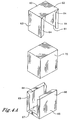
- Figures 4A and 4B depict another possible embodiment of the present invention in exploded view and assembled views.
- Package 72 (Figure 4b) comprises a U-joint type construction. As shown in Figure 4A, three walls, top 62, side wall 61 and side wall 63, of the package are formed from a portion of a first U-shaped polymeric film 60 and the remaining three walls, bottom 67, side wall 66 and side wall 68, of the package are formed from a portion of a second U-shaped polymeric film 65.
- the edges of the U-shaped portions may further comprise sealing edges or flaps, one of which is identified in each portion as 64 and 69 respectively.
- At least one wall of at least one U-shaped portion comprises an evacuator.
- the second U-shaped portion comprising the bottom 67 may be placed, for example on the bottom platen of a baler.
- a material to be packaged 70 for example a fibrous material, may be placed on top of the bottom 67.
- the first U-shaped portion 60, comprising the top 62 may then be placed on top of the material to be packaged 70.
- the side walls 61, 63, 65 and 68 may then be folded around the material and the edges sealed to the other side walls and top 62 and bottom 67 using the flaps to form package 72.
- the package may then be evacuated.
- the first U-shaped portion may be placed on top of the material and the material compressed prior to folding the side walls around the material and sealing.
- Figure 5 illustrates an alternate embodiment of the present invention.
- a bulk material 100 may be packaged utilizing the present invention.
- Packaging material may comprise component parts 110,120, 130 and 140, formed, for example from the types of laminates described herein.
- each component piece may include flange like edges, 112, 114, 116 and 118 on piece 110; 122, 124, 126, and 128 on piece 120; 132, 134, 136 and 138 on piece 130; and 142,144,146 and 148 on piece 140.
- edges of corresponding pairs may be sealed to form larger pieces. As shown in Figure 5, edge 112 of piece 110 and edge 122 of piece 120 are sealed to form seal 152. Similarly, edge 132 of piece 130 and edge 142 of piece 140 are sealed to form seal 162.
- the larger pieces thus formed may be placed on the top and on the bottom of the bulk material to form a package with the bulk material inside.
- the remaining edges of the packaging material may then be sealed to completely seal the package.
- Seals 172 and 182 are shown in “D” of Figure 5.
- Extra packaging material will form flaps, 192, 194, 196 and 198.
- the flaps may be folded over and sealed to the side walls of the package to form a package of the present invention, 200, as shown in Figure 5 "E".
- At least one piece of packaging material includes an evacuator to facilitate creation of a vacuum within the package.
- Figures 2, 3, 4 and 5 illustrate substantially cubiodal chambers that will form substantially cubiodal packages.
- the present invention produces packages of different shapes.
- the present invention produces packages of non-uniform or random shapes.
- the principals of the present invention may be utilized with chambers in the forms of bags to produce packages that conform to the shape of the fibers in the interior volume of the bag.
- Many of the features and advantages of the present invention will be achieved with non-uniform packages, although such packages may be less advantageous for stacking and palleting.
- packages produced with the method of the present invention are advantageous for use with a wide variety of fibers.
- An embodiment of the present invention produces a package for acetate tow fibers of the type utilized for filter material.
- a package produced with the method of the present invention may comprise: a sealed chamber at a pressure less than atmospheric pressure, the interior volume of the chamber comprising acetate fibers.
- FIGS 6A, 6B, 6C and 6D depict a vacuum outlet assembly used in the present invention, suitable for use as an evacuator in embodiments of the present invention.
- a vacuum outlet assembly may comprise a vacuum outlet 302, gasket 304, and cap 306.
- the vacuum outlet comprises an aperture 312 that permits air flow between the interior and exterior of a package.
- the aperture may include multiple holes 314, or a single hole.
- the aperture may advantageously take the form of a check valve that allows one way flow from the interior to exterior of a package.
- the aperture portion may be raised with respect to the base, 304 of the vacuum outlet, creating wall 316 that allows the aperture to extend through packaging material.
- the portion of wall 316 that will protrude through the packaging material may comprise a flanged portion 318 to facilitate connection to a vacuum drawing device.
- the base 302 is placed on one side of packaging material and wall 316 extends through hole or slits in the packaging material such that flange 318 is on the opposite side of the packaging material than base 302.
- Gasket 304, having opening 305 adapted to fit around the walls 316 of outlet 302 may be placed over the flange to secure the assembly.
- the assembly may be glued and/or sealed to the packaging material.
- Cap 306 is provided to seal the aperture 312 as shown in Figure 6B. Alternatively, 312 may be sealed with glue or packaging material after a vacuum has been drawn.
- the vacuum outlet assembly may be formed from a moldable and/or machinable materials, including but not limited to polymeric material including nylon, LLDPE, or the like; metal; wood etc..
- the vacuum outlet assembly may be produced by molding and/or machining using conventional techniques.
- vacuum outlet 302 may be substantially circular and include radially extending pieces 322 for strength.
- the vacuum outlet may include a sloped plateau portion 324 near the aperture.
- the underside of vacuum outlet 302 may comprise channels 326 and wedge portions 322 corresponding to the radially extending pieces.
- the channels and wedge portions help provide structural shape to the vacuum outlet assembly.
- the vacuum assembly is substantially round and the connector to a vacuum drawing device is round.
- the base of the vacuum assembly will be larger than the aperture to provide structural support to the aperture and the package walls.
- the larger base assembly will, also help prevent the assembly from pulling through the walls of the package and provide a larger sealing surface.
- the base is 1.5 to 20 times larger than the aperture.
- the diameter of the aperture was approximately 26 centimeters and the diameter of the base was approximately 80 centimeters.
- FIG. 7 An embodiment of an apparatus used in the present invention is depicted in Figure 7.
- the apparatus may comprise a packaging system of the type depicted in Figure 2.
- the apparatus may further comprise a vessel 84 suitable for receiving fibers 82 and a ram 86.
- the ram may be hydraulic and operated by motors and associated control equipment (not shown).
- the apparatus may further comprise an evacuation system 88.
- the evacuation system comprises a vacuum pulling device 90 and associated hoses 92 adapted to be connected to an evacuator 26 in a wall of the packaging system.
- the bottom surface of a packaging system may be placed in the vessel. Fibers may be placed on top of the bottom surface and the side surfaces and top surface placed around the fibers. The fibers may then be compressed using ram 86. After compression, the hose 92 from evacuation system 88 may be connected to evacuator 26 to remove air and gases from the chamber until the chamber reaches a desired pressure less than ambient atmospheric pressure.
- control The advantages of an embodiment of a package produced with the method of the present invention comprising fibers are illustrated with reference to a typical prior art bale referred to as control.
- Baling equipment manufactured by Lummus Corporation, Savannah, Georgia was utilized to produce a typical prior art bale as a control, and an embodiment of the present invention.
- the baler bin was filled with acetate tow to a level so that after compression the bale dimensions were approximately 94 centimeters ("cm") in width, 122 cm in length and 112 cm in height. After removal of compressive force the new bale dimensions were approximately 99 cm in width, 127 cm in length and 123 cm in height.
- the bale was then packaged with cardboard and plastic sheets along the sides of the bale and 10 plastic straps surrounding the bale. After removal from the baling equipment the bale was stored and grew approximately 18 cm in height for a approximate bale dimension of 99 cm in width, 127 cm in length and 141 cm in height The density of the bale was about 0.4 grams per cubic centimeter and the bale weighed approximately 726 kilograms (kg). The resulting bale had strap indentation that were apparent on visible inspection and was domed approximately 5 cm in the center on the top and bottom. As a result, the bale was insufficiently flat and had to be stacked on its side.
- the bottom wall was installed on the lower section of a fiber-holding chamber of processing equipment conventionally utilized to compress bale fibers.
- the fiber holding chamber was filled with acetate tow fiber on top of the bottom wall.
- the top wall was placed over the fiber accumulated in the chamber.
- a compression cycle was performed to create a rectangular cubiodal shape. While maintaining compression, the chamber walls of the fiber-holding chamber were removed and the girth wrap (side walls) were wrapped around the compressed acetate tow.
- An airtight seal was made on the pre-folded edges of the forward and trailing edges of the girth wrap by heat sealing.
- the matching pre-folded edges of the top and bottom of the girth wrap, top wall, bottom wall were also sealed by heat sealing, thereby creating a hermetically sealed chamber.
- a vacuum hose was applied to the vacuum check valve in a side wall (panel of the girth wrap) of the chamber.
- the chamber was evacuated by pulling a vacuum until the expansion forces of the acetate tow fiber reached equilibrium and the acetate tow fiber applied little or no outward forces on the walls of the chamber.
- the vacuum hose was removed and the vacuum check valve retained the vacuum in the chamber. The compression from the processing equipment was released.
- the resulting package Upon removal from the baler the resulting package retained a substantially cubiodal shape with approximately the following dimensions 98 cm width, 123 cm length, 127 cm height and contained approximately 975 kilograms of acetate tow fiber.
- the average density of acetate tow fibers within the package was approximately 0.64 grams per cubic centimeter.
- Expansion was minimal during storage with the package retaining a substantially cubiodal shape with approximately the following dimensions 98 cm width, 123 cm length, and 129 cm height.
- the bale was substantially flat on the top and bottom to within 0.35 centimeters.
- This Example illustrates embodiments of the present invention.
- a package produced with the method of the present invention was formed in the manner indicated in Figure 5 by splicing portions of a Bx4 Nylon/Valeron/ULLDPE film together for form two film pieces approximately 243 centimeters by 269 centimeters.
- Other laminates such as PET-SiOx/Valeron/ULLDPE would be expected to perform in a similar fashion.
- a hole, approximately 2.8 centimeters in diameter was punch cut into one of the film pieces to provide an aperture for a vacuum outlet assembly substantially as described in Figures 6A, 6B, 6C and 6D.
- a heat sealer was used to seal the vacuum outlet assembly to the film piece.
- the other film piece was then placed in the baler bin of a conventional baling apparatus, such as described elsewhere herein.
- Cellulose acetate tow fibers were fed into the baler bin, on top of the film piece, to provide a finished compressed bale approximately 127 centimeters tall.
- the first film piece was then placed over the platen of the baling apparatus so that when the platen moved to compress the cellulose acetate tow fibers the film piece would cover the top and top side portions of the fibers.
- the fibers were then compressed.
- a soft rubber gasket was placed over the portion of the vacuum outlet assembly extended through the film.
- the hose was disconnected and a cap placed over the aperture.
- baler platen The compressive force exterted by the baler platen was removed and the resulting bale removed from the baler.
- a conventional shrink wrap was placed over the bale and the bale checked for vacuum leaks.
Landscapes
- Mechanical Engineering (AREA)
- Engineering & Computer Science (AREA)
- Chemical & Material Sciences (AREA)
- Dispersion Chemistry (AREA)
- Packages (AREA)
- Packaging Of Annular Or Rod-Shaped Articles, Wearing Apparel, Cassettes, Or The Like (AREA)
- Auxiliary Devices For And Details Of Packaging Control (AREA)
- Vacuum Packaging (AREA)
- Basic Packing Technique (AREA)
- Yarns And Mechanical Finishing Of Yarns Or Ropes (AREA)
- Preliminary Treatment Of Fibers (AREA)
- Storage Of Harvested Produce (AREA)
- Press Drives And Press Lines (AREA)
- Wrappers (AREA)
- Polysaccharides And Polysaccharide Derivatives (AREA)
Claims (6)
- Verfahren zum Verpacken von elastischen Fasern, umfassend:das Bereitstellen von Fasern;das Komprimieren der Fasern;das Bilden einer dicht verschließbaren Kammer um die Fasern herum, wobeimindestens eine Wand der Kammer eine Evakuierungsvorrichtung umfasst; das Verschließen der Kammer;das Evakuieren der Kammer durch die Evakuierungsvorrichtung und dann das Aufheben der Kompression.
- Verfahren nach Anspruch 1, in der die Evakuierungsvorrichtung ein Vakuumrückschlagventil ist.
- Verfahren nach Anspruch 1 oder 2, in dem die verschlossene Kammer bei einem Innendruck von 16.000 bis unter 101.325 Pa ein Innenvolumen aufweist.
- Verfahren nach Anspruch 1 oder 2, in dem die Fasern aus Acetat-Towfaser besteht und die Dichte der verpackten Acetat-Towfaser 0,50 bis 0,78 g/cm3 beträgt.
- Verfahren nach Anspruch 1, in dem die Wände der Kammer eine Polymerfolie umfassen, die Polyethylen, Polypropylen, Ethylen-Vinylalkohol-Polymer, Nylon, Mylar, Polyethylenterephthalat, Polyethylenterephthalatglycol, Polyimide oder Polyamide umfasst.
- Verfahren nach Anspruch 4, in dem die Wände weiter ein Feuchtigkeitsbarriereelement umfassen.
Priority Applications (1)
| Application Number | Priority Date | Filing Date | Title |
|---|---|---|---|
| EP06017172A EP1717163B1 (de) | 2003-02-14 | 2004-02-11 | Ballen, sowie Verfahren zu dessen Herstellung |
Applications Claiming Priority (5)
| Application Number | Priority Date | Filing Date | Title |
|---|---|---|---|
| US672825 | 1991-03-21 | ||
| US44744003P | 2003-02-14 | 2003-02-14 | |
| US447440P | 2003-02-14 | ||
| US10/672,825 US7306093B2 (en) | 2003-02-14 | 2003-09-26 | Packages, packaging systems, methods for packaging and apparatus for packaging |
| PCT/US2004/004001 WO2004074134A1 (en) | 2003-02-14 | 2004-02-11 | Bale, and method and apparatus for forming it |
Related Child Applications (2)
| Application Number | Title | Priority Date | Filing Date |
|---|---|---|---|
| EP06017172A Division EP1717163B1 (de) | 2003-02-14 | 2004-02-11 | Ballen, sowie Verfahren zu dessen Herstellung |
| EP06017172.5 Division-Into | 2006-08-17 |
Publications (3)
| Publication Number | Publication Date |
|---|---|
| EP1599394A1 EP1599394A1 (de) | 2005-11-30 |
| EP1599394B1 true EP1599394B1 (de) | 2006-11-22 |
| EP1599394B2 EP1599394B2 (de) | 2010-06-16 |
Family
ID=32853500
Family Applications (2)
| Application Number | Title | Priority Date | Filing Date |
|---|---|---|---|
| EP04710228A Expired - Lifetime EP1599394B2 (de) | 2003-02-14 | 2004-02-11 | Verfahren zur bildung von faserballen |
| EP06017172A Expired - Lifetime EP1717163B1 (de) | 2003-02-14 | 2004-02-11 | Ballen, sowie Verfahren zu dessen Herstellung |
Family Applications After (1)
| Application Number | Title | Priority Date | Filing Date |
|---|---|---|---|
| EP06017172A Expired - Lifetime EP1717163B1 (de) | 2003-02-14 | 2004-02-11 | Ballen, sowie Verfahren zu dessen Herstellung |
Country Status (12)
| Country | Link |
|---|---|
| US (6) | US7306093B2 (de) |
| EP (2) | EP1599394B2 (de) |
| JP (4) | JP2006517896A (de) |
| KR (2) | KR101126897B1 (de) |
| CN (1) | CN100384703C (de) |
| AT (2) | ATE484464T1 (de) |
| BR (1) | BRPI0406888A (de) |
| CA (1) | CA2515053E (de) |
| DE (2) | DE602004029612D1 (de) |
| MX (1) | MXPA05008470A (de) |
| RU (1) | RU2333142C2 (de) |
| WO (1) | WO2004074134A1 (de) |
Families Citing this family (50)
| Publication number | Priority date | Publication date | Assignee | Title |
|---|---|---|---|---|
| EP1448814A4 (de) * | 2001-10-01 | 2005-09-14 | Rtica Inc | Verfahren und vorrichtung zur herstellung eines isolationsprodukts |
| US7600635B2 (en) * | 2002-04-22 | 2009-10-13 | Dietmar Kern | Highly compressed filter tow bales and process for their production |
| US7306093B2 (en) | 2003-02-14 | 2007-12-11 | Eastman Chemical Company | Packages, packaging systems, methods for packaging and apparatus for packaging |
| US20050284775A1 (en) * | 2003-02-14 | 2005-12-29 | Mclaughlin Michael R | Packages, packaging systems, methods for packaging, and apparatuses for packaging |
| US20050131368A2 (en) | 2003-03-04 | 2005-06-16 | Diaperoos, Llc | Vacuum-packed diaper |
| US20090071862A2 (en) | 2003-03-04 | 2009-03-19 | Diaperoos, Llc | Indicia of reduced diaper viewable through encasement |
| JP3848319B2 (ja) * | 2003-11-11 | 2006-11-22 | キヤノン株式会社 | 情報処理方法及び情報処理装置 |
| US7730832B2 (en) | 2005-04-28 | 2010-06-08 | Eastman Chemical Company | Method and apparatus for forming a bale having substantially flat upper and lower surfaces |
| US7424850B2 (en) | 2005-05-09 | 2008-09-16 | Celanese Acetate Llc | Fiber bale and a method for producing the same |
| US7591388B2 (en) * | 2005-07-12 | 2009-09-22 | Philip Salvatore Amormino | Spill-resistant container |
| US7487720B2 (en) | 2007-03-05 | 2009-02-10 | Celanese Acetate Llc | Method of making a bale of cellulose acetate tow |
| DE102007015554A1 (de) * | 2007-03-29 | 2008-10-02 | Hans Adler Ohg | Mehrschichtige Folie und Verpackung aus dieser Folie |
| WO2009078298A1 (ja) * | 2007-12-14 | 2009-06-25 | Denki Kagaku Kogyo Kabushiki Kaisha | 人工毛髪用繊維の梱包方法及び梱包体 |
| JP2009154926A (ja) * | 2007-12-27 | 2009-07-16 | British American Tobacco Pacific Corporation | たばこ産業製品用の包装材料 |
| JP5315100B2 (ja) * | 2009-03-18 | 2013-10-16 | 株式会社ニューフレアテクノロジー | 描画装置 |
| JP4619453B2 (ja) | 2009-03-31 | 2011-01-26 | ダイセル化学工業株式会社 | 圧縮されたフィルタトウ梱包体の梱包方法 |
| US20110017625A1 (en) * | 2009-07-22 | 2011-01-27 | Simplicity Products International, Inc. | Cubic eco-package for liquid products with finger engageable pull |
| WO2011034949A2 (en) * | 2009-09-15 | 2011-03-24 | WestPoint Home, Inc. | Environmentally friendly textile soft goods retail packaging incorporting vacuum-sealable bags reusable by consumers |
| USD653548S1 (en) | 2009-10-12 | 2012-02-07 | Jeffrey Wycoff | Plastic container with handle |
| JP5542455B2 (ja) * | 2010-01-18 | 2014-07-09 | 三菱電機株式会社 | 梱包装置 |
| JP5557594B2 (ja) * | 2010-05-13 | 2014-07-23 | 株式会社ダイセル | フィルタトウベールの梱包用フィルム材セットと、それを用いたフィルタトウベールの梱包方法 |
| US20130239523A1 (en) * | 2011-02-07 | 2013-09-19 | Erik D. Scudder | Systems and methods for packaging and transporting bulk materials |
| US20130098785A1 (en) * | 2011-10-20 | 2013-04-25 | Marcos Andre Steffens | Vacuum packing methods and apparatus for tobacco |
| CN103204278B (zh) * | 2013-03-08 | 2015-07-08 | 宁波市东盛纺织有限公司 | 一种可以打包的纺织物压缩机 |
| CN103204311B (zh) * | 2013-05-03 | 2015-01-14 | 友达光电股份有限公司 | 防潮纸箱 |
| US10716326B2 (en) | 2014-03-11 | 2020-07-21 | Daicel Corporation | Package of filter tow bale packed with packing material in a non-hermetic state and manufacturing method thereof |
| JP6113297B2 (ja) * | 2014-03-17 | 2017-04-12 | 株式会社クリンペット・ジャパン | 紙製積層束の梱包方法及びその方法により梱包された紙製積層束の梱包体 |
| GB201412350D0 (en) | 2014-07-11 | 2014-08-27 | Knauf Insulation | Insulating package |
| US10661966B2 (en) * | 2014-10-29 | 2020-05-26 | Link Snacks, Inc. | Container with oxygen and moisture barrier and scavenger capability |
| JP6436533B2 (ja) * | 2015-02-20 | 2018-12-12 | 株式会社ダイセル | アセテートトウベールが梱包材で非密封状態に梱包された梱包体の製造方法 |
| EP3088309A1 (de) | 2015-04-29 | 2016-11-02 | Solvay Acetow GmbH | Verfahren zum herstellen eines verpackten filter tow-ballens |
| CA3026579C (en) | 2015-06-05 | 2024-10-22 | Intermodal Sciences, Llc | CONTAINER FOR TRANSPORTING BULK LIQUIDS USING ENCLOSED TRAILERS |
| US20170008220A1 (en) * | 2015-07-10 | 2017-01-12 | Area Studio, Llc | Method for embossing a fabric product while the product is situated in packaging |
| CN105968756B (zh) * | 2016-05-28 | 2017-09-29 | 吉林省亿阳升生物环保科技有限公司 | 一种可生物降解的聚乳酸‑纤维复合材料的制备方法 |
| KR101792708B1 (ko) | 2016-06-22 | 2017-11-02 | 삼성중공업(주) | 유체냉각장치 |
| CN109641691B (zh) * | 2017-02-27 | 2020-09-04 | 田边刚士 | 温度管理罐 |
| USD885929S1 (en) * | 2017-08-18 | 2020-06-02 | Standlee Hay Company | Hay and straw compressed bale product packaging |
| CN108328030A (zh) * | 2017-12-19 | 2018-07-27 | 红云红河烟草(集团)有限责任公司 | 一种针对打叶复烤后碎片打包包装方法 |
| CA3028781A1 (en) * | 2018-01-08 | 2019-07-08 | Gumpro Drilling Fluids Pvt. Ltd. | Apparatus and method for vacuum packaging solid drilling fluid additives |
| CN108624016B (zh) * | 2018-04-24 | 2021-03-23 | 上海交通大学 | 芳纶纤维改性碳纤维增强聚乳酸热塑性复合材料及制备方法 |
| DE102020103017A1 (de) * | 2019-02-06 | 2020-08-06 | Zeitgeist Ventures Deutschland GmbH | Smartfilter |
| CN109760898B (zh) * | 2019-03-31 | 2020-11-13 | 江苏露姿玛俪食品有限公司 | 一种用于茶叶包装机的包装系统 |
| EP4085008A4 (de) | 2019-12-31 | 2024-06-05 | RLMB Group, LLC | Systeme, verfahren und vorrichtung zur erzeugung einer umhüllung, einer regulierten atmosphäre und funktionsbehandlungen für verderbliche produkte |
| JP2022147093A (ja) * | 2021-03-23 | 2022-10-06 | 帝人株式会社 | カットファイバーの梱包体および梱包方法 |
| US12263974B2 (en) * | 2021-05-28 | 2025-04-01 | Rlmb Group, Llc | System, method and apparatus for sealing and applying modified atmosphere for bulk perishable bins |
| KR20240135743A (ko) * | 2021-10-21 | 2024-09-12 | 아쎄테이트 인터내셔널 엘엘씨 | 하부 시트를 포함하는 포장된 섬유 재료 베일 |
| EP4437864A4 (de) * | 2021-11-24 | 2025-09-10 | Daicel Corp | Towstreifen für beheizten zigarettenfilter und towstreifenverpackungsartikel für beheizten zigarettenfilter |
| CN114435682B (zh) * | 2022-03-31 | 2023-08-11 | 浙江经贸职业技术学院 | 基于真空压缩和自动封口的物流包装设备及方法 |
| USD1067632S1 (en) * | 2024-09-27 | 2025-03-25 | Shenzhen Zelin Innovation Technology Co., Ltd. | Vacuum compression bag |
| CN119873133B (zh) * | 2025-01-22 | 2025-10-28 | 江苏华越毛纺有限公司 | 纺织品存储组件 |
Family Cites Families (172)
| Publication number | Priority date | Publication date | Assignee | Title |
|---|---|---|---|---|
| US206658A (en) | 1878-08-06 | Improvement in baling-presses | ||
| US159378A (en) * | 1875-02-02 | Improvement in methods of fastening cotton-bales | ||
| US1468130A (en) * | 1918-07-06 | 1923-09-18 | Edward H Angier | Bale |
| US1452100A (en) * | 1918-08-12 | 1923-04-17 | Edward H Angier | Package |
| GB398144A (en) | 1933-03-24 | 1933-09-07 | Krupp Fried Grusonwerk Ag | Improvements in or relating to baling presses |
| CH256382A (de) | 1942-12-03 | 1948-08-15 | Int Cellucotton Products Compa | Verfahren zur Herstellung von Packungen aus aus gekreppten Blättern aus Zellulosefasern bestehenden Stapeln, Vorrichtung zur Durchführung dieses Verfahrens und nach diesem Verfahren hergestellte Packung. |
| US2764859A (en) * | 1950-09-18 | 1956-10-02 | Norman K Hanselmann | Method of packaging compressible articles |
| CA639825A (en) | 1952-12-05 | 1962-04-17 | Eastman Kodak Company | Filter tow treated with sorbitan compounds |
| US2841500A (en) * | 1953-04-10 | 1958-07-01 | Tri State Proc Company | Method of packaging and preserving hops |
| US2780838A (en) * | 1954-04-19 | 1957-02-12 | Pacific Mills | Textile fiber package |
| US2927722A (en) * | 1954-11-10 | 1960-03-08 | Melvin R Metzger | Vacuum type valve-equipped containers |
| US2814382A (en) * | 1955-09-21 | 1957-11-26 | Frederic H Lassiter | Cellophane packaging and method |
| US3016581A (en) | 1957-11-07 | 1962-01-16 | Eastman Kodak Co | Apparatus for opening continuous multifilament crimped tow |
| BE573050A (de) | 1957-11-07 | |||
| US3063363A (en) | 1960-01-18 | 1962-11-13 | Lamb Grays Harbor Co Inc | Convex upper platen for a pulp press |
| GB896228A (en) | 1960-05-05 | 1962-05-09 | Lamb Grays Harbor Co Inc | Convex upper platen for a pulp press |
| FR1271646A (fr) | 1960-08-03 | 1961-09-15 | Cellophane Sa | Procédé d'emballage de produits volumineux compressibles, comme des pelotes de filà tricoter |
| BE609949A (fr) | 1960-11-16 | 1962-03-01 | Spinnfaser Ag | Emballage pour laine cellulosique ou analogues, dépourvu de cordelettes ou bandes d'attache |
| US3120893A (en) | 1961-06-19 | 1964-02-11 | Eastman Kodak Co | Tow bale |
| US3206021A (en) * | 1961-06-19 | 1965-09-14 | Eastman Kodak Co | Tow bale |
| US3246443A (en) | 1961-09-07 | 1966-04-19 | Gen Tire & Rubber Co | Foam cushion material packaging |
| SE319722B (de) | 1964-06-17 | 1970-01-19 | Duplan Ab | |
| US3407562A (en) * | 1965-05-11 | 1968-10-29 | Gen Electric | Capacitor assembly method |
| US3381440A (en) | 1965-05-18 | 1968-05-07 | Owens Corning Fiberglass Corp | Method and apparatus for handling and packaging material |
| US3458966A (en) * | 1966-03-24 | 1969-08-05 | Owens Corning Fiberglass Corp | Method of packaging compressible material |
| FR1480095A (fr) | 1966-05-18 | 1967-05-05 | Owens Corning Fiberglass Corp | Procédé et appareil pour manipuler et emballer des matières fibreuses ayant la forme de nattes |
| GB1156860A (en) | 1966-10-20 | 1969-07-02 | Saint Gobain | Process and Apparatus for the Packaging of Panels of Elastic Fibrous or Cellular Material, for example Glass Fibre. |
| DE1536009A1 (de) | 1966-11-26 | 1970-07-23 | Dunlopillo Gmbh | Vakuumverpackter Feststoffkoerper |
| US3499261A (en) * | 1968-04-26 | 1970-03-10 | Owens Corning Fiberglass Corp | Method and apparatus for handling and packaging material |
| DE1934073A1 (de) | 1968-07-04 | 1970-02-26 | Roehrenwerk Und Pumpenfabrik R | Verfahren zum Silieren von Erntegut |
| ES375795A1 (es) | 1969-07-19 | 1972-08-16 | Cassina Centro Srl | Procedimiento para el embalaje a volumen reducido de mue- bles y similares. |
| BE757192A (fr) | 1969-10-10 | 1971-03-16 | Lindemann Maschfab Gmbh | Procede de pressage et d'emballage de balles notamment de balles de matiere fibreuse, et presse pour la mise en oeuvre de ce procede |
| US3641734A (en) | 1970-05-15 | 1972-02-15 | Francis B Fishburne | Apparatus for packing loose compressible material in rectangular containers |
| US3968877A (en) | 1970-08-17 | 1976-07-13 | E. I. Du Pont De Nemours & Company | High density tow cartons |
| GB1310029A (en) | 1970-08-24 | 1973-03-14 | Ici Ltd | Packaging filamentary tows |
| GB1438481A (en) | 1971-02-02 | 1976-06-09 | Robinson W S | Vehicle crash barriers |
| JPS5435553B2 (de) | 1971-09-01 | 1979-11-02 | ||
| GB1384080A (en) | 1971-11-13 | 1975-02-19 | Davis Ind Equipment Ltd | Pressing and baling apparatus |
| US3991670A (en) | 1972-04-25 | 1976-11-16 | Sunds Aktiebolag | Apparatus for baling fibrous material |
| DK128526C (da) | 1972-05-08 | 1983-02-28 | P Suhr | Apparat til emballering af kompressible varer |
| US3816970A (en) * | 1972-06-09 | 1974-06-18 | Lummus Industries | Apparatus for wrapping bagging and the like about bales of fibers |
| FR2202498A5 (de) | 1972-10-11 | 1974-05-03 | Boutillier Ets | |
| US3824758A (en) | 1973-05-10 | 1974-07-23 | British American Tobacco Co | Method and apparatus for packing compressible material such as tobacco |
| US3914918A (en) * | 1973-11-08 | 1975-10-28 | Hartford Fibres Ltd | Method of packaging flock fibres |
| US3846955A (en) | 1974-04-08 | 1974-11-12 | Du Pont | Process for packaging acrylic fibers |
| US4054204A (en) | 1974-12-23 | 1977-10-18 | Heidi Keeton | Compressed foam article |
| US4055203A (en) * | 1975-12-12 | 1977-10-25 | Thermoguard Insulation Co. | Loose fill cellulose insulation material packing machine |
| US4075817A (en) | 1976-04-14 | 1978-02-28 | Gieske Jr Edward T | Apparatus for baling compressible material |
| JPS5314093A (en) | 1976-07-21 | 1978-02-08 | Saito Tetsukoushiyo Kk | Rattan packing device |
| JPS5314094A (en) | 1976-07-21 | 1978-02-08 | Saito Tetsukoushiyo Kk | Rattan packing device |
| JPS5321689A (en) * | 1976-08-11 | 1978-02-28 | Okabe Metal Ind | Bag for accommodating beddingglike article |
| DE7635849U1 (de) * | 1976-11-13 | 1977-03-03 | Rhodiaceta Ag | Verpackung fuer zusammengepresste Fasern Faeden oder Fadenkabel |
| JPS5374994A (en) | 1976-12-10 | 1978-07-03 | Kawasaki Heavy Ind Ltd | Method of packing tow |
| SE7705269L (sv) | 1977-05-05 | 1978-11-06 | Ab Sunds | Sett och anordning att genom pressning overfora voluminost material till balar |
| JPS54163161U (de) | 1978-05-08 | 1979-11-15 | ||
| JPS54163161A (en) * | 1978-06-14 | 1979-12-25 | Toray Industries | Method of making package for wadding |
| US4324176A (en) * | 1980-02-07 | 1982-04-13 | E. I. Du Pont De Nemours And Company | Tow baling |
| US4411122A (en) * | 1980-05-23 | 1983-10-25 | Oscar Mayer & Co., Inc. | Apparatus and method for pressure resizing of products |
| FR2510515B1 (fr) * | 1981-07-31 | 1985-12-06 | Saint Gobain Isover | Procede pour le conditionnement de panneaux d'un materiau compressible et conditionnements realises par ce procede |
| DE3137344A1 (de) * | 1981-09-19 | 1983-04-28 | Vogel, Christian, Dr., 8048 Zürich | Faserballenpresse |
| JPS5951019A (ja) * | 1982-09-03 | 1984-03-24 | 有限会社柏木研究所 | 羽毛ブトン等の真空包装方法及び装置 |
| JPS5951019B2 (ja) | 1982-09-13 | 1984-12-12 | 株式会社ゼネラル・リサ−チ・オブ・エレクトロニツクス | ライトペン |
| US4457125A (en) | 1983-04-22 | 1984-07-03 | Fishburne Francis B | Press for packing compressible material having an air release sleeve |
| US4553668A (en) * | 1983-05-19 | 1985-11-19 | Hayssen Manufacturing Company | Packing articles, such as packages of rolls of paper |
| SU1505438A3 (ru) * | 1984-03-19 | 1989-08-30 | Джуль но Маньи и Дино-Франко Маньи (IT) | Способ упаковывани матраца |
| SU1214526A1 (ru) | 1984-03-30 | 1986-02-28 | Краснодарский Научно-Исследовательский Институт Пищевой Промышленности | Способ упаковки табака |
| US4577752A (en) | 1984-05-04 | 1986-03-25 | Eastman Kodak Company | High density tow bale and method for forming it |
| DE3444897A1 (de) | 1984-12-08 | 1986-06-12 | Bayer Ag, 5090 Leverkusen | Mineralwollegebinde und verfahren zu dessen herstellung |
| US4716712A (en) * | 1985-03-04 | 1988-01-05 | Owens-Corning Fiberglas Corporation | Apparatus for packaging loose fibrous material |
| GB8613760D0 (en) | 1986-06-06 | 1986-07-09 | Fiberglas Canada Inc | Packaging compressible items |
| ES2030790T3 (es) * | 1987-06-10 | 1992-11-16 | Autefa Maschinenfabrik Gmbh | Procedimiento y dispositivo para el embalaje de pacas prensadas. |
| DE3732376A1 (de) * | 1987-09-25 | 1989-04-06 | Fleissner Maschf Ag | Verfahren zum verpacken von faserigem gut in ballen sowie geeignete faserballenpresse dazu |
| DE3732390A1 (de) | 1987-09-25 | 1989-04-06 | Fleissner Maschf Ag | Faserballenpresse |
| US4817365A (en) | 1987-11-13 | 1989-04-04 | Owens-Corning Fiberglas Corporation | Fibrous insulation batt packaging machine |
| US4805383A (en) * | 1988-01-11 | 1989-02-21 | Manville Corporation | Batt packaging machine and method |
| US6035608A (en) | 1997-06-19 | 2000-03-14 | Stac-Pac Technologies Inc. | Packaging a strip of material |
| US5921064A (en) | 1997-06-16 | 1999-07-13 | Kt Holdings, Inc. | Packaging a strip of material |
| US6321511B1 (en) * | 1988-05-20 | 2001-11-27 | Bki Holding Corporation | Packaging a strip of material with compression to reduce volume |
| JPH0692331B2 (ja) | 1988-08-05 | 1994-11-16 | 呉羽化学工業株式会社 | ベンゼンまたはモノ置換ベンゼンの塩素化方法 |
| US5097956A (en) * | 1988-09-07 | 1992-03-24 | Paramount Packaging Corporation | Vacuum package with smooth surface and method of making same |
| JPH0298517A (ja) * | 1988-09-29 | 1990-04-10 | Mitsubishi Heavy Ind Ltd | 真空乾燥による保管装置 |
| US4910955A (en) | 1988-10-24 | 1990-03-27 | Corsello Thomas G | Horseshoe trimming device |
| US4910855A (en) * | 1989-03-31 | 1990-03-27 | Hoechst Celanese Corporation | Weighted bale blanket and method for using the same |
| EP0420071B1 (de) | 1989-09-29 | 1994-06-08 | Mitsubishi Jukogyo Kabushiki Kaisha | Verfahren zum Verpacken durch Zusammenpressen und Vorrichtung zum Bündeln von zu verpackenden Produkten |
| JPH03124518A (ja) * | 1989-09-29 | 1991-05-28 | Mitsubishi Heavy Ind Ltd | 圧縮梱包方法 |
| JPH0753210Y2 (ja) | 1990-03-30 | 1995-12-06 | 株式会社小糸製作所 | 車両用灯具 |
| DE4015642A1 (de) | 1990-05-15 | 1991-11-21 | Autefa Maschinenfab | Verfahren und vorrichtung zum umschlagen einer deckfolie um einen pressballen |
| JP3193730B2 (ja) * | 1990-09-07 | 2001-07-30 | 義信 山口 | 脱気包装袋の弁構造体及び復元防止体 |
| JPH04142255A (ja) * | 1990-09-26 | 1992-05-15 | Earth Chem Corp Ltd | 包装具 |
| US5174198A (en) | 1990-10-31 | 1992-12-29 | Weyerhaeuser Company | Method for packaging and shipping fiber materials |
| JPH0692331A (ja) * | 1992-06-30 | 1994-04-05 | Yasuo Shibata | クッション類の包装方法 |
| FR2693980B1 (fr) | 1992-07-23 | 1994-09-16 | Vetrotex France Sa | Procédé et dispositif de conditionnement. |
| CN2137244Y (zh) * | 1992-08-15 | 1993-06-30 | 白新德 | 一种新型储物袋 |
| DE9217335U1 (de) | 1992-12-18 | 1993-03-04 | Ferdl Polzer-Maschinen, 6348 Herborn | Abfallpresse für Verpackungsmaterial |
| JPH06238839A (ja) | 1993-02-15 | 1994-08-30 | Mitsubishi Plastics Ind Ltd | 布団圧縮包装用複合フイルム |
| BE1008199A5 (fr) * | 1993-03-16 | 1996-02-13 | Vieslet Jean Paul | Procede pour faconner un bloc de forme et dimensions stables a partir d'un melange de polymeres. |
| GB9312155D0 (en) | 1993-06-12 | 1993-07-28 | Carobel Foam Ltd | Compression packed foam pet bed |
| US5480030A (en) * | 1993-12-15 | 1996-01-02 | New West Products, Inc. | Reusable, evacuable enclosure for storage of clothing and the like |
| US6408872B1 (en) | 1993-12-15 | 2002-06-25 | New West Products, Inc. | Evacuable container having one-way valve with filter element |
| DE4343960C2 (de) | 1993-12-22 | 1999-04-22 | Rhodia Acetow Ag | Vorrichtung zum Sammeln und Verpacken von Verpackungen sowie Verwendung der Vorrichtung |
| DE4405120A1 (de) | 1994-02-17 | 1995-08-31 | Autefa Maschinenfabrik Gmbh Au | Verfahren und Vorrichtung zum Verpacken von Preßballen sowie Packmittelzuschnitt |
| JP3003479U (ja) | 1994-04-25 | 1994-10-18 | 化研工業株式会社 | 被服、その他の可圧縮物の圧縮密封袋 |
| WO1996004170A1 (en) * | 1994-08-05 | 1996-02-15 | Fishburne International, Inc. | Method and apparatus for producing compressed fibers |
| US5491017A (en) * | 1994-10-14 | 1996-02-13 | Transhield, Inc. | Shrink wrap material and method for protecting articles |
| PL322685A1 (en) | 1995-04-04 | 1998-02-16 | Simmons Co | Method of packaging elastically comporessible articles |
| ZA963563B (en) | 1995-05-15 | 1996-11-19 | Saint Gobain Isover | Process and device for compressing and packaging compressible products |
| GB9513051D0 (en) | 1995-06-27 | 1995-08-30 | British American Tobacco Co | Method and apparatus for the manufacture of filter-tipped cigarettes |
| CA2154035C (en) | 1995-07-17 | 2005-12-06 | Brian Keith Orchard | Under deck fastening system |
| NL1001039C2 (nl) | 1995-08-24 | 1997-02-25 | Kiggen Beheer Bv | Container voor het opnemen van afval. |
| NL1001306C2 (nl) | 1995-09-28 | 1997-04-03 | V O F Handelsonderneming Ruvo | Diervoedingsmiddel. |
| DE19536505A1 (de) * | 1995-09-29 | 1997-04-10 | Biotec Biolog Naturverpack | Biologisch abbaubares Filtermaterial und Verfahren zu seiner Herstellung |
| US5664408A (en) * | 1995-10-20 | 1997-09-09 | Chesterfield; Michael P. | Apparatus for vacuum packaging a soft product |
| US5732531A (en) * | 1995-10-30 | 1998-03-31 | Hoechst Celanese Corporation | Reusable bale wrap kit for compressed, resilient fibers |
| DE29517428U1 (de) | 1995-11-03 | 1996-01-04 | Cyklop GmbH, 50996 Köln | Packstück-Umreifungsmaschine, insbesondere für eine sich kreuzende Umreifung von Ballen aus einem zusammenpreßbaren Material, wie vor allem Faservlies oder sonstigem Fasermaterial |
| JP2710035B2 (ja) * | 1995-12-19 | 1998-02-10 | 有限会社もりもと商事 | 真空パッキングタオル |
| DE29615598U1 (de) | 1996-09-06 | 1996-12-19 | Strautmann Umwelttechnik und Recycling Gesellschaft mbH und Co.KG, 49326 Melle | Preßschild und Auswerfer für Ballenpresse |
| RU2126857C1 (ru) * | 1996-09-20 | 1999-02-27 | Шини Энтэрпрайс Ко., Лтд. | Гофрированная конструкция волокнистого наполнителя и способ ее изготовления |
| US5845462A (en) | 1996-12-10 | 1998-12-08 | Northfield Corporation | Coupon inserter |
| US6729471B2 (en) * | 1997-06-16 | 2004-05-04 | Bki Holding Corporation | Packaging a strip of material with compression to reduce volume |
| US6067775A (en) * | 1997-11-18 | 2000-05-30 | Stac-Pac Technologies Inc. | Packaging a strip of material by folding |
| US5956926A (en) | 1997-06-19 | 1999-09-28 | Kt Holdings, Inc. | Packaging a strip of material by folding and cutting the folded package |
| FR2771375A1 (fr) | 1997-11-25 | 1999-05-28 | Saint Gobain Isover | Procede et dispositif de conditionnement de materiaux compressibles |
| JP3789624B2 (ja) * | 1997-12-03 | 2006-06-28 | 大日本印刷株式会社 | 受像シート |
| US6032446A (en) | 1998-04-06 | 2000-03-07 | Deere & Company | Densification method and apparatus for harvested cotton or other similar fibrous material |
| EP0968642B1 (de) | 1998-07-01 | 2007-03-07 | Land Holding S.A. | Vorrichtung um Futter zu behandeln insbesondere Rundballen aus Heu |
| JP3124518B2 (ja) | 1998-07-15 | 2001-01-15 | タイユ株式会社 | 切削油の供給回収方法及び切削油 |
| US6033113A (en) * | 1998-08-18 | 2000-03-07 | Cti Industries Corporation | Seal for zipper-type plastic bags and the like |
| JP3057167U (ja) * | 1998-08-31 | 1999-03-30 | 株式会社アール | 圧縮保存袋用吸引ノズル |
| US6056439A (en) * | 1999-01-28 | 2000-05-02 | Fres-Co System Usa, Inc. | High flow/volume valve for flexible packaging |
| SE515445C2 (sv) | 1999-02-22 | 2001-08-06 | Glenn Gustafsson | Förfarande och anordning för inpackning av mjuka element |
| US6293075B1 (en) * | 1999-03-08 | 2001-09-25 | Bki Holding Corporation | Packaging a strip of material |
| US6202849B1 (en) | 1999-07-07 | 2001-03-20 | David B. Graham | Evacuatable rigid storage unit for storing compressible articles therein |
| RU2174936C2 (ru) | 1999-07-07 | 2001-10-20 | Акционерное общество открытого типа "Научно-исследовательский институт точного и электронного машиностроения" | Устройство для упаковывания в вакууме изделий в пластиковые пакеты |
| US6116781A (en) * | 1999-08-13 | 2000-09-12 | New West Products, Inc. | Storage bag with one-way air valve |
| US6135253A (en) | 1999-08-24 | 2000-10-24 | Weissman; Ira B. | Suitcase with compressible packing system |
| JP2001173818A (ja) | 1999-12-21 | 2001-06-29 | Furuya Kogyo Kk | 逆止弁、圧縮収納用包装袋及び緩衝用具 |
| JP2001206322A (ja) | 2000-01-21 | 2001-07-31 | Namiki Toyoaki | 発泡体製品の圧縮包装方法及び圧縮包装された発泡体製品 |
| JP3070701U (ja) * | 2000-02-02 | 2000-08-15 | 株式会社アール | 圧縮収納袋の吸引ノズル |
| DE10006372A1 (de) * | 2000-02-12 | 2001-08-16 | Hauni Maschinenbau Ag | Verfahren und Vorrichtung zum fortlaufenden Verdichten eines bewegten Stromes aus Filtermaterial |
| JP2001287714A (ja) | 2000-04-11 | 2001-10-16 | Kosugi Shoten:Kk | 発泡ポリウレタン等からなる素材の包装方法 |
| DE20008174U1 (de) * | 2000-05-05 | 2001-09-27 | AUTEFA Automation GmbH, 86316 Friedberg | Hilfsvorrichtung zum Öffnen von gepressten Faserballen |
| US6499574B1 (en) * | 2000-08-03 | 2002-12-31 | Michael M. Anthony | Vacuum-packed luggage and method of manufacture |
| AU1697502A (en) | 2000-10-20 | 2002-04-29 | Rhodia Acetow Gmbh | Highly compressed filter tow bales |
| US20020133131A1 (en) * | 2001-01-09 | 2002-09-19 | Krishnakumar Rangachari | Absorbent material incorporating synthetic fibers and process for making the material |
| ITMI20010488A1 (it) | 2001-03-08 | 2002-09-08 | Goglio Spa Luigi Milano | Metodo ed apparecchiatura per realizzare in modo completamente automatico il riempimento e la chiusura sotto vuoto di coppie di contenitori |
| FR2834920B1 (fr) * | 2002-01-22 | 2004-04-09 | Valois Sa | Dispositif de pulverisation a actionnement lateral |
| WO2003082701A1 (en) | 2002-03-26 | 2003-10-09 | Diliberto Samuel L Jr | Disaster pack and method for making same |
| DE10217840B4 (de) | 2002-04-22 | 2013-10-17 | Rhodia Acetow Gmbh | Ballen aus lagenförmig angeordnetem Filter Tow sowie Verfahren zum Verpacken von Filter Tow |
| US7600635B2 (en) | 2002-04-22 | 2009-10-13 | Dietmar Kern | Highly compressed filter tow bales and process for their production |
| JP2004034062A (ja) | 2002-07-01 | 2004-02-05 | Mitsubishi Rayon Co Ltd | ベール包装用物品の圧縮装置と同圧縮方法 |
| US6927429B2 (en) * | 2003-02-14 | 2005-08-09 | Freescale Semiconductor, Inc. | Integrated circuit well bias circuity |
| US7306093B2 (en) | 2003-02-14 | 2007-12-11 | Eastman Chemical Company | Packages, packaging systems, methods for packaging and apparatus for packaging |
| JP2005022733A (ja) | 2003-07-01 | 2005-01-27 | Toyo Tire & Rubber Co Ltd | コンデンサー絶縁油用酸化防止袋 |
| US7588160B2 (en) * | 2004-01-14 | 2009-09-15 | Highland Champ Corporation | Combined storage apparatus |
| EP1566337A1 (de) | 2004-02-20 | 2005-08-24 | Rockwool International A/S | Vorrichtung und Verpackungsverfahren für die Verpackung von Mineralwollprodukte, und Mineralwollverpackung |
| RU44105U1 (ru) | 2004-11-02 | 2005-02-27 | Закрытое акционерное общество "ТАУРАС-ФЕНИКС" | Вакуумная установка |
| DE102004054437B4 (de) | 2004-11-11 | 2012-01-26 | Volkswagen Ag | Verfahren zur automatischen Steuerung und/oder Regelung einer Bewegung eines Fahrzeugs während eines Einparkvorgangs |
| DE202005010864U1 (de) * | 2004-11-15 | 2005-09-22 | Takata-Petri Ag | Airbagmodul zum Einbau in ein Kraftfahrzeug |
| US7730832B2 (en) | 2005-04-28 | 2010-06-08 | Eastman Chemical Company | Method and apparatus for forming a bale having substantially flat upper and lower surfaces |
| US7424850B2 (en) * | 2005-05-09 | 2008-09-16 | Celanese Acetate Llc | Fiber bale and a method for producing the same |
| JP5041273B2 (ja) * | 2005-06-28 | 2012-10-03 | 株式会社Sumco | 容器包装装置 |
| JP2007261656A (ja) | 2006-03-29 | 2007-10-11 | Daicel Chem Ind Ltd | 圧縮された被梱包体の梱包方法及び梱包装置 |
| DE102006061309A1 (de) | 2006-12-22 | 2008-07-03 | Jörg von Seggern Maschinenbau GmbH | Verfahren zum gasdichten Verpacken von Gegenständen und Anlage zum gasdichten Verpacken von Gegenständen |
| US7487720B2 (en) * | 2007-03-05 | 2009-02-10 | Celanese Acetate Llc | Method of making a bale of cellulose acetate tow |
| RU2347729C2 (ru) | 2007-03-26 | 2009-02-27 | Закрытое акционерное общество научно-производственное предприятие "АДОНИС" | Устройство для упаковывания в вакууме изделий в пластиковые пакеты |
| ATE549252T1 (de) | 2007-07-16 | 2012-03-15 | Cryovac Inc | Vakuum-skin-verpackungsverfahren und -vorrichtung |
| RU2385830C1 (ru) | 2008-09-12 | 2010-04-10 | Общество с ограниченной ответственностью "Холдинговая компания Аскона" | Способ упаковки матрасов |
| JP5374994B2 (ja) | 2008-09-25 | 2013-12-25 | ソニー株式会社 | ミリ波誘電体内伝送装置 |
| JP5387890B2 (ja) | 2009-02-25 | 2014-01-15 | カシオ計算機株式会社 | 印刷装置、印刷制御方法、印刷制御プログラムが記憶された記憶媒体 |
| RU89842U1 (ru) | 2009-08-17 | 2009-12-20 | Общество с ограниченной ответственностью "Унипак-Л" | Вакуумно-упаковочная машина для упаковки денежных купюр |
| JP5314093B2 (ja) | 2010-08-31 | 2013-10-16 | シャープ株式会社 | 照明装置、前照灯および移動体 |
| JP5314094B2 (ja) | 2010-08-31 | 2013-10-16 | シャープ株式会社 | 照明装置、前照灯および移動体 |
-
2003
- 2003-09-26 US US10/672,825 patent/US7306093B2/en not_active Expired - Lifetime
-
2004
- 2004-02-11 AT AT06017172T patent/ATE484464T1/de not_active IP Right Cessation
- 2004-02-11 AT AT04710228T patent/ATE345992T1/de not_active IP Right Cessation
- 2004-02-11 KR KR1020057014870A patent/KR101126897B1/ko not_active Expired - Fee Related
- 2004-02-11 JP JP2006503492A patent/JP2006517896A/ja not_active Withdrawn
- 2004-02-11 MX MXPA05008470A patent/MXPA05008470A/es active IP Right Grant
- 2004-02-11 WO PCT/US2004/004001 patent/WO2004074134A1/en not_active Ceased
- 2004-02-11 KR KR1020117007273A patent/KR101126914B1/ko not_active Expired - Fee Related
- 2004-02-11 EP EP04710228A patent/EP1599394B2/de not_active Expired - Lifetime
- 2004-02-11 EP EP06017172A patent/EP1717163B1/de not_active Expired - Lifetime
- 2004-02-11 CN CNB2004800042954A patent/CN100384703C/zh not_active Expired - Fee Related
- 2004-02-11 DE DE602004029612T patent/DE602004029612D1/de not_active Expired - Lifetime
- 2004-02-11 CA CA2515053A patent/CA2515053E/en not_active Expired - Fee Related
- 2004-02-11 RU RU2005128562/04A patent/RU2333142C2/ru active
- 2004-02-11 BR BR0406888-2A patent/BRPI0406888A/pt not_active Application Discontinuation
- 2004-02-11 DE DE602004003349T patent/DE602004003349T3/de not_active Expired - Lifetime
-
2006
- 2006-07-27 US US11/494,109 patent/US20060272960A1/en not_active Abandoned
- 2006-08-31 US US11/514,420 patent/US7739857B2/en not_active Expired - Lifetime
-
2009
- 2009-04-27 JP JP2009108335A patent/JP5148552B2/ja not_active Expired - Fee Related
-
2010
- 2010-05-05 US US12/774,384 patent/US7958696B2/en not_active Expired - Lifetime
- 2010-12-03 JP JP2010270441A patent/JP5562817B2/ja not_active Expired - Fee Related
-
2011
- 2011-04-29 US US13/097,953 patent/US8671652B2/en not_active Expired - Lifetime
-
2012
- 2012-07-27 JP JP2012166927A patent/JP5635564B2/ja not_active Expired - Fee Related
-
2014
- 2014-01-29 US US14/167,847 patent/US9598184B2/en not_active Expired - Fee Related
Also Published As
Similar Documents
| Publication | Publication Date | Title |
|---|---|---|
| EP1599394B1 (de) | Verfahren zur bildung von faserballen | |
| US20050284775A1 (en) | Packages, packaging systems, methods for packaging, and apparatuses for packaging | |
| JP3917590B2 (ja) | 高圧縮フィルタートウベール、およびその製造プロセス | |
| EP2236427B1 (de) | Verfahren zum Verpacken eines verdichteten Filter Tow Ballens |
Legal Events
| Date | Code | Title | Description |
|---|---|---|---|
| PUAI | Public reference made under article 153(3) epc to a published international application that has entered the european phase |
Free format text: ORIGINAL CODE: 0009012 |
|
| 17P | Request for examination filed |
Effective date: 20050808 |
|
| AK | Designated contracting states |
Kind code of ref document: A1 Designated state(s): AT BE BG CH CY CZ DE DK EE ES FI FR GB GR HU IE IT LI LU MC NL PT RO SE SI SK TR |
|
| AX | Request for extension of the european patent |
Extension state: AL LT LV MK |
|
| GRAP | Despatch of communication of intention to grant a patent |
Free format text: ORIGINAL CODE: EPIDOSNIGR1 |
|
| DAX | Request for extension of the european patent (deleted) | ||
| RTI1 | Title (correction) |
Free format text: METHOD FOR FORMING FIBERS BALES |
|
| GRAS | Grant fee paid |
Free format text: ORIGINAL CODE: EPIDOSNIGR3 |
|
| GRAA | (expected) grant |
Free format text: ORIGINAL CODE: 0009210 |
|
| AK | Designated contracting states |
Kind code of ref document: B1 Designated state(s): AT BE BG CH CY CZ DE DK EE ES FI FR GB GR HU IE IT LI LU MC NL PT RO SE SI SK TR |
|
| PG25 | Lapsed in a contracting state [announced via postgrant information from national office to epo] |
Ref country code: SK Free format text: LAPSE BECAUSE OF FAILURE TO SUBMIT A TRANSLATION OF THE DESCRIPTION OR TO PAY THE FEE WITHIN THE PRESCRIBED TIME-LIMIT Effective date: 20061122 Ref country code: IT Free format text: LAPSE BECAUSE OF FAILURE TO SUBMIT A TRANSLATION OF THE DESCRIPTION OR TO PAY THE FEE WITHIN THE PRESCRIBED TIME-LIMIT;WARNING: LAPSES OF ITALIAN PATENTS WITH EFFECTIVE DATE BEFORE 2007 MAY HAVE OCCURRED AT ANY TIME BEFORE 2007. THE CORRECT EFFECTIVE DATE MAY BE DIFFERENT FROM THE ONE RECORDED. Effective date: 20061122 Ref country code: NL Free format text: LAPSE BECAUSE OF FAILURE TO SUBMIT A TRANSLATION OF THE DESCRIPTION OR TO PAY THE FEE WITHIN THE PRESCRIBED TIME-LIMIT Effective date: 20061122 Ref country code: SI Free format text: LAPSE BECAUSE OF FAILURE TO SUBMIT A TRANSLATION OF THE DESCRIPTION OR TO PAY THE FEE WITHIN THE PRESCRIBED TIME-LIMIT Effective date: 20061122 Ref country code: RO Free format text: LAPSE BECAUSE OF FAILURE TO SUBMIT A TRANSLATION OF THE DESCRIPTION OR TO PAY THE FEE WITHIN THE PRESCRIBED TIME-LIMIT Effective date: 20061122 Ref country code: FI Free format text: LAPSE BECAUSE OF FAILURE TO SUBMIT A TRANSLATION OF THE DESCRIPTION OR TO PAY THE FEE WITHIN THE PRESCRIBED TIME-LIMIT Effective date: 20061122 Ref country code: LI Free format text: LAPSE BECAUSE OF FAILURE TO SUBMIT A TRANSLATION OF THE DESCRIPTION OR TO PAY THE FEE WITHIN THE PRESCRIBED TIME-LIMIT Effective date: 20061122 Ref country code: CZ Free format text: LAPSE BECAUSE OF FAILURE TO SUBMIT A TRANSLATION OF THE DESCRIPTION OR TO PAY THE FEE WITHIN THE PRESCRIBED TIME-LIMIT Effective date: 20061122 Ref country code: AT Free format text: LAPSE BECAUSE OF FAILURE TO SUBMIT A TRANSLATION OF THE DESCRIPTION OR TO PAY THE FEE WITHIN THE PRESCRIBED TIME-LIMIT Effective date: 20061122 Ref country code: CH Free format text: LAPSE BECAUSE OF FAILURE TO SUBMIT A TRANSLATION OF THE DESCRIPTION OR TO PAY THE FEE WITHIN THE PRESCRIBED TIME-LIMIT Effective date: 20061122 |
|
| REG | Reference to a national code |
Ref country code: GB Ref legal event code: FG4D |
|
| REG | Reference to a national code |
Ref country code: CH Ref legal event code: EP |
|
| REG | Reference to a national code |
Ref country code: IE Ref legal event code: FG4D |
|
| REF | Corresponds to: |
Ref document number: 602004003349 Country of ref document: DE Date of ref document: 20070104 Kind code of ref document: P |
|
| PG25 | Lapsed in a contracting state [announced via postgrant information from national office to epo] |
Ref country code: SE Free format text: LAPSE BECAUSE OF FAILURE TO SUBMIT A TRANSLATION OF THE DESCRIPTION OR TO PAY THE FEE WITHIN THE PRESCRIBED TIME-LIMIT Effective date: 20070222 Ref country code: DK Free format text: LAPSE BECAUSE OF FAILURE TO SUBMIT A TRANSLATION OF THE DESCRIPTION OR TO PAY THE FEE WITHIN THE PRESCRIBED TIME-LIMIT Effective date: 20070222 Ref country code: BG Free format text: LAPSE BECAUSE OF FAILURE TO SUBMIT A TRANSLATION OF THE DESCRIPTION OR TO PAY THE FEE WITHIN THE PRESCRIBED TIME-LIMIT Effective date: 20070222 |
|
| PG25 | Lapsed in a contracting state [announced via postgrant information from national office to epo] |
Ref country code: MC Free format text: LAPSE BECAUSE OF NON-PAYMENT OF DUE FEES Effective date: 20070228 |
|
| PG25 | Lapsed in a contracting state [announced via postgrant information from national office to epo] |
Ref country code: ES Free format text: LAPSE BECAUSE OF FAILURE TO SUBMIT A TRANSLATION OF THE DESCRIPTION OR TO PAY THE FEE WITHIN THE PRESCRIBED TIME-LIMIT Effective date: 20070305 |
|
| PG25 | Lapsed in a contracting state [announced via postgrant information from national office to epo] |
Ref country code: PT Free format text: LAPSE BECAUSE OF FAILURE TO SUBMIT A TRANSLATION OF THE DESCRIPTION OR TO PAY THE FEE WITHIN THE PRESCRIBED TIME-LIMIT Effective date: 20070423 |
|
| NLV1 | Nl: lapsed or annulled due to failure to fulfill the requirements of art. 29p and 29m of the patents act | ||
| REG | Reference to a national code |
Ref country code: CH Ref legal event code: PL |
|
| EN | Fr: translation not filed | ||
| PLBI | Opposition filed |
Free format text: ORIGINAL CODE: 0009260 |
|
| 26 | Opposition filed |
Opponent name: RHODIA ACETOW GMBH Effective date: 20070814 |
|
| PLAX | Notice of opposition and request to file observation + time limit sent |
Free format text: ORIGINAL CODE: EPIDOSNOBS2 |
|
| PLBB | Reply of patent proprietor to notice(s) of opposition received |
Free format text: ORIGINAL CODE: EPIDOSNOBS3 |
|
| PLAY | Examination report in opposition despatched + time limit |
Free format text: ORIGINAL CODE: EPIDOSNORE2 |
|
| PG25 | Lapsed in a contracting state [announced via postgrant information from national office to epo] |
Ref country code: IE Free format text: LAPSE BECAUSE OF NON-PAYMENT OF DUE FEES Effective date: 20070212 |
|
| PG25 | Lapsed in a contracting state [announced via postgrant information from national office to epo] |
Ref country code: FR Free format text: LAPSE BECAUSE OF FAILURE TO SUBMIT A TRANSLATION OF THE DESCRIPTION OR TO PAY THE FEE WITHIN THE PRESCRIBED TIME-LIMIT Effective date: 20070713 Ref country code: GR Free format text: LAPSE BECAUSE OF FAILURE TO SUBMIT A TRANSLATION OF THE DESCRIPTION OR TO PAY THE FEE WITHIN THE PRESCRIBED TIME-LIMIT Effective date: 20070223 |
|
| PLAH | Information related to despatch of examination report in opposition + time limit modified |
Free format text: ORIGINAL CODE: EPIDOSCORE2 |
|
| PLBC | Reply to examination report in opposition received |
Free format text: ORIGINAL CODE: EPIDOSNORE3 |
|
| PG25 | Lapsed in a contracting state [announced via postgrant information from national office to epo] |
Ref country code: FR Free format text: LAPSE BECAUSE OF FAILURE TO SUBMIT A TRANSLATION OF THE DESCRIPTION OR TO PAY THE FEE WITHIN THE PRESCRIBED TIME-LIMIT Effective date: 20061122 |
|
| PG25 | Lapsed in a contracting state [announced via postgrant information from national office to epo] |
Ref country code: EE Free format text: LAPSE BECAUSE OF FAILURE TO SUBMIT A TRANSLATION OF THE DESCRIPTION OR TO PAY THE FEE WITHIN THE PRESCRIBED TIME-LIMIT Effective date: 20061122 |
|
| PLAY | Examination report in opposition despatched + time limit |
Free format text: ORIGINAL CODE: EPIDOSNORE2 |
|
| PLBC | Reply to examination report in opposition received |
Free format text: ORIGINAL CODE: EPIDOSNORE3 |
|
| PLAB | Opposition data, opponent's data or that of the opponent's representative modified |
Free format text: ORIGINAL CODE: 0009299OPPO |
|
| PG25 | Lapsed in a contracting state [announced via postgrant information from national office to epo] |
Ref country code: LU Free format text: LAPSE BECAUSE OF NON-PAYMENT OF DUE FEES Effective date: 20070211 Ref country code: CY Free format text: LAPSE BECAUSE OF FAILURE TO SUBMIT A TRANSLATION OF THE DESCRIPTION OR TO PAY THE FEE WITHIN THE PRESCRIBED TIME-LIMIT Effective date: 20061122 |
|
| PG25 | Lapsed in a contracting state [announced via postgrant information from national office to epo] |
Ref country code: TR Free format text: LAPSE BECAUSE OF FAILURE TO SUBMIT A TRANSLATION OF THE DESCRIPTION OR TO PAY THE FEE WITHIN THE PRESCRIBED TIME-LIMIT Effective date: 20061122 Ref country code: HU Free format text: LAPSE BECAUSE OF FAILURE TO SUBMIT A TRANSLATION OF THE DESCRIPTION OR TO PAY THE FEE WITHIN THE PRESCRIBED TIME-LIMIT Effective date: 20070523 |
|
| PUAH | Patent maintained in amended form |
Free format text: ORIGINAL CODE: 0009272 |
|
| STAA | Information on the status of an ep patent application or granted ep patent |
Free format text: STATUS: PATENT MAINTAINED AS AMENDED |
|
| 27A | Patent maintained in amended form |
Effective date: 20100616 |
|
| AK | Designated contracting states |
Kind code of ref document: B2 Designated state(s): AT BE BG CH CY CZ DE DK EE ES FI FR GB GR HU IE IT LI LU MC NL PT RO SE SI SK TR |
|
| REG | Reference to a national code |
Ref country code: ES Ref legal event code: FD2A Effective date: 20070212 |
|
| PGFP | Annual fee paid to national office [announced via postgrant information from national office to epo] |
Ref country code: GB Payment date: 20150126 Year of fee payment: 12 |
|
| GBPC | Gb: european patent ceased through non-payment of renewal fee |
Effective date: 20160211 |
|
| REG | Reference to a national code |
Ref country code: DE Ref legal event code: R079 Ref document number: 602004003349 Country of ref document: DE Free format text: PREVIOUS MAIN CLASS: B65D0085160000 Ipc: B65D0085070000 |
|
| PG25 | Lapsed in a contracting state [announced via postgrant information from national office to epo] |
Ref country code: GB Free format text: LAPSE BECAUSE OF NON-PAYMENT OF DUE FEES Effective date: 20160211 |
|
| PGFP | Annual fee paid to national office [announced via postgrant information from national office to epo] |
Ref country code: DE Payment date: 20220112 Year of fee payment: 19 |
|
| PGFP | Annual fee paid to national office [announced via postgrant information from national office to epo] |
Ref country code: BE Payment date: 20220114 Year of fee payment: 19 |
|
| REG | Reference to a national code |
Ref country code: DE Ref legal event code: R119 Ref document number: 602004003349 Country of ref document: DE |
|
| REG | Reference to a national code |
Ref country code: BE Ref legal event code: MM Effective date: 20230228 |
|
| PG25 | Lapsed in a contracting state [announced via postgrant information from national office to epo] |
Ref country code: DE Free format text: LAPSE BECAUSE OF NON-PAYMENT OF DUE FEES Effective date: 20230901 |
|
| PG25 | Lapsed in a contracting state [announced via postgrant information from national office to epo] |
Ref country code: BE Free format text: LAPSE BECAUSE OF NON-PAYMENT OF DUE FEES Effective date: 20230228 |