EP1595645A1 - Diamantscheibe - Google Patents
Diamantscheibe Download PDFInfo
- Publication number
- EP1595645A1 EP1595645A1 EP03780867A EP03780867A EP1595645A1 EP 1595645 A1 EP1595645 A1 EP 1595645A1 EP 03780867 A EP03780867 A EP 03780867A EP 03780867 A EP03780867 A EP 03780867A EP 1595645 A1 EP1595645 A1 EP 1595645A1
- Authority
- EP
- European Patent Office
- Prior art keywords
- diamond
- disc
- grinding
- region
- diamond grains
- Prior art date
- Legal status (The legal status is an assumption and is not a legal conclusion. Google has not performed a legal analysis and makes no representation as to the accuracy of the status listed.)
- Withdrawn
Links
Images


Classifications
-
- B—PERFORMING OPERATIONS; TRANSPORTING
- B24—GRINDING; POLISHING
- B24D—TOOLS FOR GRINDING, BUFFING OR SHARPENING
- B24D7/00—Bonded abrasive wheels, or wheels with inserted abrasive blocks, designed for acting otherwise than only by their periphery, e.g. by the front face; Bushings or mountings therefor
- B24D7/06—Bonded abrasive wheels, or wheels with inserted abrasive blocks, designed for acting otherwise than only by their periphery, e.g. by the front face; Bushings or mountings therefor with inserted abrasive blocks, e.g. segmental
- B24D7/063—Bonded abrasive wheels, or wheels with inserted abrasive blocks, designed for acting otherwise than only by their periphery, e.g. by the front face; Bushings or mountings therefor with inserted abrasive blocks, e.g. segmental with segments embedded in a matrix which is rubbed away during the grinding process
-
- B—PERFORMING OPERATIONS; TRANSPORTING
- B24—GRINDING; POLISHING
- B24B—MACHINES, DEVICES, OR PROCESSES FOR GRINDING OR POLISHING; DRESSING OR CONDITIONING OF ABRADING SURFACES; FEEDING OF GRINDING, POLISHING, OR LAPPING AGENTS
- B24B23/00—Portable grinding machines, e.g. hand-guided; Accessories therefor
- B24B23/02—Portable grinding machines, e.g. hand-guided; Accessories therefor with rotating grinding tools; Accessories therefor
- B24B23/028—Angle tools
-
- B—PERFORMING OPERATIONS; TRANSPORTING
- B24—GRINDING; POLISHING
- B24B—MACHINES, DEVICES, OR PROCESSES FOR GRINDING OR POLISHING; DRESSING OR CONDITIONING OF ABRADING SURFACES; FEEDING OF GRINDING, POLISHING, OR LAPPING AGENTS
- B24B27/00—Other grinding machines or devices
- B24B27/06—Grinders for cutting-off
- B24B27/08—Grinders for cutting-off being portable
-
- B—PERFORMING OPERATIONS; TRANSPORTING
- B24—GRINDING; POLISHING
- B24D—TOOLS FOR GRINDING, BUFFING OR SHARPENING
- B24D3/00—Physical features of abrasive bodies, or sheets, e.g. abrasive surfaces of special nature; Abrasive bodies or sheets characterised by their constituents
- B24D3/02—Physical features of abrasive bodies, or sheets, e.g. abrasive surfaces of special nature; Abrasive bodies or sheets characterised by their constituents the constituent being used as bonding agent
- B24D3/04—Physical features of abrasive bodies, or sheets, e.g. abrasive surfaces of special nature; Abrasive bodies or sheets characterised by their constituents the constituent being used as bonding agent and being essentially inorganic
- B24D3/06—Physical features of abrasive bodies, or sheets, e.g. abrasive surfaces of special nature; Abrasive bodies or sheets characterised by their constituents the constituent being used as bonding agent and being essentially inorganic metallic or mixture of metals with ceramic materials, e.g. hard metals, "cermets", cements
- B24D3/10—Physical features of abrasive bodies, or sheets, e.g. abrasive surfaces of special nature; Abrasive bodies or sheets characterised by their constituents the constituent being used as bonding agent and being essentially inorganic metallic or mixture of metals with ceramic materials, e.g. hard metals, "cermets", cements for porous or cellular structure, e.g. for use with diamonds as abrasives
-
- B—PERFORMING OPERATIONS; TRANSPORTING
- B24—GRINDING; POLISHING
- B24D—TOOLS FOR GRINDING, BUFFING OR SHARPENING
- B24D5/00—Bonded abrasive wheels, or wheels with inserted abrasive blocks, designed for acting only by their periphery; Bushings or mountings therefor
- B24D5/12—Cut-off wheels
-
- B—PERFORMING OPERATIONS; TRANSPORTING
- B24—GRINDING; POLISHING
- B24D—TOOLS FOR GRINDING, BUFFING OR SHARPENING
- B24D7/00—Bonded abrasive wheels, or wheels with inserted abrasive blocks, designed for acting otherwise than only by their periphery, e.g. by the front face; Bushings or mountings therefor
- B24D7/06—Bonded abrasive wheels, or wheels with inserted abrasive blocks, designed for acting otherwise than only by their periphery, e.g. by the front face; Bushings or mountings therefor with inserted abrasive blocks, e.g. segmental
-
- B—PERFORMING OPERATIONS; TRANSPORTING
- B28—WORKING CEMENT, CLAY, OR STONE
- B28D—WORKING STONE OR STONE-LIKE MATERIALS
- B28D1/00—Working stone or stone-like materials, e.g. brick, concrete or glass, not provided for elsewhere; Machines, devices, tools therefor
- B28D1/02—Working stone or stone-like materials, e.g. brick, concrete or glass, not provided for elsewhere; Machines, devices, tools therefor by sawing
- B28D1/12—Saw-blades or saw-discs specially adapted for working stone
- B28D1/121—Circular saw blades
-
- B—PERFORMING OPERATIONS; TRANSPORTING
- B24—GRINDING; POLISHING
- B24D—TOOLS FOR GRINDING, BUFFING OR SHARPENING
- B24D2203/00—Tool surfaces formed with a pattern
Definitions
- the present invention relates to a diamond disc mounted to a disc grinder or the like which is a hand-held rotating tool (hand-held rotating device) to, for example, grind (herein and in the claims, "grind” is meant to include “cut” except for a specified case) materials to be ground such as concrete or stone.
- Such a diamond disc is mounted to a rotating shaft of a hand-held rotating device such as a disc grinder by a mounting hole formed at the center region of the base and is rotated at a predetermined speed, to thereby cause the disc surface to grind materials to be ground (polished), for example, concrete, stone, tile, or coatings applied to their surfaces.
- a hand-held rotating device such as a disc grinder
- the diamond discs vary sizes (diameters) or configurations of discs, sizes or arrangement densities of the diamond grains bound on the disc surfaces, according to uses.
- the conventional diamond discs have technical problems as described below.
- a rearward diamond is positioned behind a forward diamond on a common rotational track in actual grinding.
- the rearward diamond tends not to serve to perform grinding efficiently, which reduces entire grinding efficiency.
- relatively adhesive materials which are represented by peeling or the like of, for example, elastic coatings.
- the diamond grains on the disc surface wear unevenly according to a degree to which they have performed grinding after a long-time use. As a result, grinding efficiency thereafter decreases and a lifetime of the diamond disc decreases.
- the conventional diamond discs are used exclusively for grinding, including chamfering or the like by the disc surface, and are not configured for other uses.
- the present invention has been made under the circumstances, and a first object of the present invention is to provide a grinding diamond disc which is used as in conventional commercially available diamond discs, which enables all diamond grains to perform grinding efficiently and uniformly, which is less likely to unevenly wear the diamond grains after a long-time use, and which is capable of efficiently discharging ground chips from a center region to an outer peripheral region of a disc surface thereof.
- a second object of the present invention is to provide a grinding diamond disc which is easily positioning diamond grains on the disc surface regardless of the number of and arrangement of diamond grains bound on the disc surface.
- a third object of the present invention is to provide a grinding diamond disc which allows a manufacture or the like of the diamond disc to be easily identified by its external appearance using diamond grains whose grinding amount (load) is smaller, among the diamond grains bound on the disc surface, and which is novel and superior in design.
- a fourth object of the present invention is to provide a grinding diamond disc which can be configured for uses other than grinding in a limited sense on the disc surface.
- a grinding diamond disc of a first invention comprises: a plurality of diamond grains bound on a grinding surface of the disc, wherein a distance between diamond grains which are located forward and rearward in a rotational direction on a common rotational track is set longer than a distance between diamond grains which are located on adjacent rotational tracks in a radial direction of the disc so as to be close to each other.
- the diamond disc Since the individual diamond grains wear substantially evenly, the diamond disc exhibits stable grinding performance for a long time period, and hence a lifetime of the diamond disc can be extended.
- the plurality of diamond grains may be arranged regularly. Thereby, the ground chips are discharged smoothly and the diamond disc can be manufactured with higher yield.
- the plurality of diamond grains may be arranged regularly in such a manner that a gap formed between diamond grains which are located on the adjacent rotational tracks and are located forward and rearward so as to be close to each other in the rotational direction is configured to extend continuously from an outer periphery of a center region to a peripheral edge region, and the gap extends continuously in such a manner that an outer diameter end thereof deviates from an inner diameter end thereof such that the inner diameter end is located forward in the rotational direction and the outer diameter end is located rearward in the rotational direction.
- the ground chips are discharged more smoothly from the gap between the diamond grains by the rotation of the diamond disc.
- the gap may be configured to extend in a swirl shape such that the outer diameter end of the gap deviates from the inner diameter end by 20 degrees or more. This enables the ground chips to be discharged more smoothly by the rotation of the grinding diamond disc.
- a grinding diamond disc of a second invention comprises a plurality of diamond grains bound on a grinding portion of the disc, wherein the plurality of diamond grains are bound on the grinding portion in such a manner that a plurality of adjacent diamond grains are patterned in a predetermined configuration to form diamond group units which are arranged regularly on the grinding portion.
- the diamond group units in one or plural patterns may be arranged as units on the grinding portion such as the disc surface, considering only the arrangement of the diamond units. This makes it possible that the diamond grains are positioned or bound on the grinding portion such as the disc surface quickly and easily. Since the plurality of diamond grains belonging to the same diamond group unit are arranged to be close to each other and to extend in a plane, and perform grinding as a unit, one diamond group unit may be substantially assumed as one large diamond.
- the grinding diamond disc exhibits grinding performance substantially as high as that of the conventional diamond disc constructed such that the individual diamond grains are positioned with respect to the grinding portion such as the disc surface.
- the diamond grains are not intended to be arranged in one pattern but may be arranged in various patterns.
- the diamond group units may be oriented in different directions according to grinding loads (loads)of the diamond grains. This changes rotational tracks of the individual diamond grains belonging to the same diamond group unit. In other words, the width of the rotational tracks of the diamond group units can be changed by orienting the diamond group units in different diamond grains. With this construction, the grinding load of the diamond grains can be adjusted. If the diamond group units are displaced from each other in the radial direction to cause the rotational tracks partially overlap with each other, the diamond group units which overlap with each other are oriented in opposite directions. Thereby, grinding uneveness is avoided, and hence difference (variation) in the grinding amount which would be caused by the difference in arrangement of the diamond grains, will not occur. As a result, the diamond grains efficiently function, and hence entire grinding efficiency increases.
- the grinding portion may be formed by a substantially flat or round face, and the diamond group units may be arranged continuously in a swirl shape from an inner diameter end side of the grinding portion to an outer diameter end side thereof.
- the diamond group units are easily arranged entirely in a well-balanced manner on the surface of the grinding portion (e.g., disc surface) for the purpose of practicability.
- the diamond disc which is easily used according to uses is easily obtained.
- the diamond group units may be arranged in the shape of one or more swirls.
- the grinding portion may be formed by a substantially flat or round face, and the diamond group units may be arranged to have a gap which gradually decreases toward the outer diameter end of the grinding portion.
- the diamond group units are arranged entirely in a well-balanced manner on the disc surface which is the grinding portion for the purpose of practicability (grinding).
- a circumferential speed of the disc increases as it is close to the outer peripheral region in the grinding portion such as the disc surface, and hence the diamond group units arranged there perform grinding with a higher degree, and bear a higher grinding load. With the above mentioned construction, this is properly performed with higher efficiency.
- the ground chips are discharged relatively easily from the outer peripheral region.
- the diamond group units may be each formed by three diamond grains arranged in a triangle shape.
- the diamond grains configured in one pattern are desirably arranged to have various orientations.
- a grinding diamond disc of a third invention comprises a plurality of diamond grains which are bound on a region of a disc surface from an outer diameter side of a center region to a peripheral edge region, and are not bound on the center region, wherein a plurality of diamond grains are arranged to form a character or a graphic drawn in a pointillist manner in at least a part of the disc surface.
- the character or graphic drawn in the pointillist manner on the disc surface which is easily noticed during grinding can display a use, performance, a manufacture or the like of the diamond disc, and its design and its commercial value are improved. Further, by arranging the character or the like at a proper position, the diamond disc thus constructed exhibits grinding performance substantially as high as that of the conventional diamond disc.
- the disc surface to which the plurality of diamond grains are bound may include a center side region and a peripheral side region located on an outer periphery of the center side region, and the diamond grains are arranged to form the character or the graphic drawn in the pointillist manner in the center side region.
- the diamond grains are arranged to draw the character or the graphic in the pointillist manner in the center side region which is low in grinding function to improve design of the disc, and the peripheral region which is high in grinding function mainly perform grinding.
- the diamond disc exhibits grinding performance substantially as high as that of the conventional diamond disc.
- the diamond disc can be identified and its design and commercial value are improved.
- a grinding diamond disc of a fourth invention having a mounting hole formed in a center region recessed backward to have a predetermined depth to thereby allow the grinding diamond disc to be mounted to a rotation device (drive shaft), comprises a plurality of diamond grains bound on a region of the disc surface which is located radially outward relative to the recessed region, wherein the diamond grains are bound from an outer peripheral edge region of the disc surface to an outer peripheral edge region of a back surface of the disc.
- the diamond disc thus constructed exhibits grinding performance substantially as high as that of the conventional diamond disc, in general grinding materials to be ground such as concrete or stone using the disc surface.
- the outer peripheral region of the disc performs cutting in a limited sense or forms a groove with respect to the materials to be ground such as concrete or stone.
- the outer peripheral region of the back surface of the disc may form a rounded surface which protrudes backward.
- Such a diamond disc efficiently performs cutting in a limited sense.
- the diamond grains may be bound from the outer peripheral edge region of the disc surface to the outer peripheral edge region of the back surface with a uniform density over an entire circumference.
- Such a diamond disc exhibits high cutting performance in a limited sense.
- a grinding diamond disc of a fifth invention which is circular in a front view, the grinding diamond disc having a mounting hole formed in a center region of a disc surface, comprises a protruding portion formed at a peripheral edge of the grinding diamond disc and configured to protrude forward and backward, wherein the diamond grains are bound on the protruding portion.
- the protruding portion efficiently performs cutting in a limited sense or forms the groove with respect to the materials to be ground such as concrete or stone. And, a region located radially inward relative to the protruding portion does not interfere with cutting performed by the protruding portion.
- the diamond grains may be bound on the protruding portion intermittently. Thereby, the ground chips are efficiently discharged in cutting or forming the groove using the protruding portion.
- ... may be rounded (formed to have a curvature) in a cross-sectional view.
- the protruding portion performs cutting or forms the groove with respect to the materials to be grounded such as concrete or stone.
- a base of the grinding diamond disc may be made of a material such as steel, resin, a composite material containing resin and reinforcement, or ceramic.
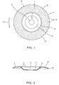
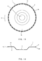
- diamond grains 2 of a relatively large size for use with a diamond disc are bound in a limited range of the disc surface (grinding surface or grinding portion) 1A formed on one side surface of a circular base 1 formed of a steel plate.
- the diamond grains 2 are of a size of #30 to #35.
- the diamond grains 2 are bound on the disc surface 1A to be fitted into brazing filler metal to a substantially half depth thereof.
- a mounting hole 3 is formed in a disc center region of the disc surface 1A to allow the disc 1 to be mounted to a disc grinder (not shown) which is a hand-held rotating device.
- the disc center region in which the mounting hole 3 is formed at the center is flat-plate shaped (flat) and is recessed backward (downward in Fig. 2) to have a predetermined depth, thereby forming a recessed portion 4.
- a region (outer peripheral region) located radially outward relative to the recessed portion 4 is rounded and protrudes forward in Fig.
- the region of the disc surface 1A from an outer periphery 5 of the outer peripheral region toward the disc outer peripheral edge 6 forms a curved surface which is curved with a curvature which gradually increases toward the disc outer peripheral edge 6.
- the diamond grains 2 are bound on the region of the disc surface 1A which extends in a range from a location slightly radially inward of the outer periphery 5 to the disc outer peripheral edge 6 by the above mentioned method.
- the diamond grains 2 are positioned on the three adjacent rotational tracks a, b, and c which are formed in the radial direction as described below.
- a distance m1 between forward and rearward diamond grains 2a which are adjacent in a rotational direction (see arrow R of Fig. 1) on the rotational track a (or rotational track b or c) is set longer than a distance m2 between the diamond 2a and diamond 2b and 2c which are located on the rotational tracks b and c adjacent on both sides of the rotational track 2a.
- the diamond grains 2 are arranged regularly.
- the diamond grains 2 are arranged in such a manner that the forward and rearward diamond grains 2 (2a) adjacent on each rotational track and the diamond grains 2 (2b and 2c) which are on rotational tracks adjacent on both sides thereof and are closest to the diamond grains 2a form a substantially diamond shape as seen in a front view.
- the diamond shape is continuously formed at plural positions to be spaced apart from one another.
- a plurality of gaps 7 which are formed between the diamond grains 2 (2a and 2b or 2a and 2c) which are located on adjacent rotational tracks and are located forward and rearward to be close to each other in a rotational direction extend in a swirl from slightly radially inward relative to the outer periphery 5 to the disc outer peripheral edge 6.
- the gaps 7 extending continuously are, as shown by gaps indicated by adjacent broken lines (imaginary reference lines) in Fig. 3, such that inner diameter ends 7a are located forward and outer diameter ends 7b are located backward in the rotational direction and extend obliquely and are curved to be rounded from the inner diameter ends 7a to the outer diameter ends 7b as seen in a front view.
- the gap 7 extends continuously in a swirl shape in such a manner that an outer diameter end portion of the gap 7 deviates from an inner diameter end portion of the gap 7 by a predetermined angle ⁇ in the rotational direction (see Fig. 3, approximately 20 degrees in this embodiment).
- the predetermined angle ⁇ may alternatively be 20 degrees or larger.
- the grinding diamond disc of the present invention constructed as described above can be mounted to the rotating shaft of the commercially available disc grinder (not shown) or the like by the mounting hole 3 formed at the center region of the diamond disc, and the individual diamond grains perform grinding efficiently in grinding of the concrete or stone.
- the grinding diamond disc of the present invention exhibits stable grinding performance and increases grinding efficiency.
- the diamond grains 2 are bound in a limited range on the disc surface (grinding surface or grinding portion) 1A formed on one surface of the circular base 1 made of the steel plate.
- the mounting hole 3 is formed at the disc center region of the disc surface 1A to thereby allow the diamond disc to be mounted to a disc grinder (not shown).
- the disc center region having the mounting hole 3 at the center thereof is flat-plate shaped (flat) and is entirely recessed backward (downward in Fig. 5) to have a predetermined depth to thereby form the recessed portion 4.
- the region (outer peripheral region) located radially outward relative to the recessed portion 4 is rounded and protrudes forward, and the region of the disc surface 1A from the outer periphery 5 to the disc outer peripheral edge 6 forms a curved surface which is curved backward with a curvature which gradually increases toward the disc outer peripheral edge 6.
- the diamond grains 2 are bound on the region of the disc surface 1A which extends in a range from a location slightly radially inward relative to the outer periphery 5 to the disc outer peripheral edge 5 by the above mentioned method.
- the diamond grains 2 are bound on the disc surface 1A in such a manner that a plurality of diamond grains 2 are patterned in a predetermined configuration to form one diamond group unit A, and a plurality of diamond group units A are arranged.
- the plurality of diamond grains 2 are patterned according to one pattern.
- the diamond group unit A of this embodiment forms a pattern in which three adjacent diamond grains 2 are located at apexes of an equilateral triangle.
- the diamond group units A are arranged on the disc surface 1A along the swirl-shaped reference line 17 which swirls from an inner diameter side to an outer diameter side in an opposite direction to the rotational direction (see arrow R of Fig. 4) of the diamond disc.
- the gap between the diamond group units A gradually decreases as it is closer to the disc outer peripheral edge 6 to increase density of the diamond grains 2 in the vicinity of the disc outer peripheral edge 6.
- the diamond group units A arranged in swirl shape substantially partially overlap with each other on the rotational track in the radial direction.
- the diamond group units A which are located forward and rearward on the swirl-shaped reference line 17 are oriented in opposite directions in the radial direction.
- the diamond group units A are not intended to be limited to arrangement in opposite directions, but may be oriented in the same direction, or otherwise, they may be oriented to be shifted by a predetermined angle, for example, 30 degrees.
- a plurality of diamond grains which are arranged effectively for grinding are patterned to form the diamond group units A which are arranged on the disc surface 1A, positioning of the diamond grains onto the disc surface 1A is achieved easily and quickly. As a result, the diamond disc can be easily obtained regardless of an increase in the number of diamond grains bound on the disc surface.
- the diamond grains 2 are bound in a limited range on the disc surface 1A (grinding surface or grinding portion) formed on one surface of the circular base 1 made of the steel plate.
- the mounting hole 3 is formed at the disc center region of the disc surface 1A to thereby allow the diamond disc to be mounted to a disc grinder which is commercially available (not shown).
- the center region having the mounting hole 3 at the center thereof is flat-plate shaped (flat) and is entirely recessed backward (downward in Fig. 7) to have a predetermined depth to thereby form the recessed portion 4.
- the region (outer peripheral region) located radially outward relative to the recessed portion 4 is rounded to protrude forward, and the region from the outer periphery 5 to the disc outer peripheral edge 6 forms a curved surface which is curved backward with a curvature which gradually increases toward the disc outer peripheral edge 6.
- the region of the disc surface 1A to which the diamond grains 2 are bound is conceptually divided into a peripheral edge side region 1a and a center side region (region closer to the center) 1b.
- the center side section 1b which is contact with the outer periphery 5 of the recessed portion 4 is formed by a substantially flat surface (to be precise a surface having a large radius curvature) as seen in a side view, and the peripheral edge side region 1a extending from this to the outer peripheral edge 6 is formed by a round surface which is rounded to retreat backward (downward in Fig. 7) toward the outer peripheral edge 6.
- the substantially flat surface and the round surface are continuous.
- the diamond grains 2 are arranged on the peripheral edge side region 1a as described below, giving importance to the grinding function.
- a plurality of diamond grains 2 are bound on the peripheral edge side region 1a in a predetermined pattern (fixed pattern) to form a plurality of diamond group units A which are arranged regularly (in a swirl shape) on the disc surface 1A.
- the diamond group unit A forms a pattern in which adjacent three diamond grains 2 are located on apexes of an equilateral triangle.
- the diamond grains 2 are, for example, temporarily bound on an adhesive sheet.
- the diamond group units A are arranged on the peripheral edge side region 1a along a swirl-shaped reference line which swirls in a direction from an inner diameter side to an outer diameter side in an opposite direction to the rotational direction (see arrow R of Fig. 6) of the diamond disc.
- the gap between the diamond group units A gradually decreases as it is closer to the disc outer peripheral edge 6 to increase density of the diamond grains 2.
- the diamond group units A arranged in swirl shape substantially partially overlap with each other on the rotational track. Also, the diamond group units A which are arranged in the swirl shape and are located forward and rearward in such a manner that the diamond group units A are oriented in opposite directions in the radial direction.
- the diamond grains 2 bound on the center side region 1b are positioned considering an external appearance.
- the diamond grains 2 are arranged on the center side region 1b to draw characters 27 (or graphics) in a pointillist manner as seen in a front view, except for a part of the center side region 1b (region closer to the center) in the radial direction, while the diamond units A are arranged in a part of the center side region 1b (region closer to the center)) in which the characters 27 are not drawn, in the swirl shape as in the peripheral edge side region 1a.
- the diamond grains 2 bound on the peripheral edge side region 1a exhibit grinding performance as in those of the conventional diamond disc.
- the diamond grains 2 are the same in the peripheral edge side region 1a and the center side region 1b. But, the diamond grains 2 bound on the center side region 1b are fewer than those bound on the peripheral edge side region 1a. This is because the diamond grains in the center side region 1b perform grinding in a lower degree and in an auxiliary manner in normal grinding.
- the diamond units A on the center side region 1b has a density lower than those on the peripheral edge side portion 1a. For this reason, the characters (or graphics) 27 drawn in the pointillist manner are easily noticed.
- the grinding diamond disc 1 of the present invention thus constructed is preferable to a user, because it is not only useful in grinding but also a manufacture or a type thereof is capable of being recognized based on the characters or the graphics drawn in a pointillist manner.
- the region in which the characters or the graphics are drawn is located at a region closer to an inner diameter which is less likely to wear with an elapse of time, they do not wear out and therefore can be recognized when the diamond disc itself is discarded.
- the diamond grains are fewer in the region in which the characters or the graphics are drawn, wasteful consumption of resource is inhibited.
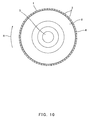
- the diamond grains 2 are bound in a limited range on the disc surface 1A which corresponds to one grinding portion formed on one surface of the circular base 1 made of the steel plate, and the disc outer peripheral edge 6 and an outer peripheral region of a back surface 8 which correspond to the other grinding function.
- the mounting hole 3 is formed at the disc center region to thereby allow the diamond disc to be mounted to the disc grinder (not shown).
- the center region of the disc surface 1A having the mounting hole 3 at the center thereof is flat-plate shaped (flat) and is entirely recessed backward (downward in Fig. 9) to have a predetermined depth to thereby form the recessed portion 4.
- the region located radially outward relative to the recessed portion 4 is configured such that the region of the disc surface 1A which extends from the outer periphery 5 of the recessed portion 4 to the disc outer peripheral edge 6 is flat-plate shaped (flat and ring-shaped).
- the region of the disc surface 1A to which the diamond grains 2 are bound is conceptually divided into the peripheral edge side region 1a and the center side region (region closer to the center) 1b.
- the diamond grains 2 are arranged on the peripheral edge side region 1a, giving attention to grinding performance. Specifically, the diamond grains 2 are arranged on the peripheral edge side region 1a in such a manner that a plurality of adjacent diamond grains 2 are patterned in a predetermined (fixed) configuration to form diamond group units A which are arranged regularly (in a swirl shape) on the disc surface 1A.
- the diamond grains 2 are patterned by, for example, a method in which the diamond grains 2 are temporarily secured on the adhesive sheet.
- the diamond group unit A of this embodiment forms a pattern in which three adjacent diamond grains 2 are located at apexes of an equilateral triangle.
- the diamond grains 2 are patterned in the configuration by, for example, a method in which the diamond grains 2 are temporarily secured on a sheet.
- the diamond group units A are arranged on the peripheral edge side region 1a in such a manner that a gap between the diamond group units A gradually decreases as it is closer to the disc outer peripheral edge 6 to increase a density of the diamond grains 2 in the vicinity of the disc outer peripheral edge 6, and to provide a uniform density over the entire periphery.
- the diamond group units A arranged in swirl shape to swirl from an inner peripheral side to an outer peripheral side in an opposite direction to the rotational direction (see arrow R of Fig. 8) of the diamond disc and are located forward and rearward substantially partially overlap with each other on the rotational track. Also, the diamond group units A which are located forward and rearward on the swirl-shaped line are oriented in opposite directions in the radial direction.
- the diamond grains 2 are continuously arranged in the form of the diamond group units A in a range from the peripheral edge portion 1a to the outer peripheral region of the back surface 8.
- the diamond grains 2 are positioned on the center side region 1b considering an external appearance.
- the plurality of diamond grains 2 are bound on the center side region 1b to draw characters 27 (or graphics) in a pointillist manner as seen in the front view except for a part (region closer to the center in this embodiment) of the center side region 1b in the radial direction, and the diamond group units A are arranged as in the peripheral edge side region 1a in a part of the center side region 1b in which the characters 27 (region closer to the center) are not drawn.
- the diamond grains 2 are bound on the region ranging from the disc outer peripheral edge 6 to the outer peripheral region of the back surface 8 in the flat and ring-shaped disc surface 1A functions as one type of a rotating edge having a predetermined thickness. For this reason, if cutting in a limited sense is performed by cutting the disc outer peripheral edge 6 of the disc surface 1A into the surface to be ground, grinding a groove or cutting in a limited sense are easily performed. In normal cutting using only the disc surface 1A, the diamond disc of this embodiment exhibits grinding performance substantially as high as the conventional diamond disc.
- the diamond grains 2 are the same in the peripheral edge side region 1a and the center side region 1b. But, the diamond grains 2 bound on the center side region 1b are fewer than those bound on the peripheral edge side region 1a. This is because the center side region 1b performs grinding in a lower degree and in an auxiliary manner in normal grinding.
- the diamond units A on the center side region 1b has a density lower than those on the peripheral edge side portion 1a. For this reason, the characters (or graphics) 27 drawn in a pointillist manner are easily noticed.
- the grinding diamond disc of the present invention constructed as described above is not only useful in grinding but also functions as one type of a rotating cutting edge, thus improving generality of the grinding diamond disc.
- the diamond disc of the present invention is preferable to the user, since the manufacture or the type of the diamond disc is recognized by the characters or the graphics drawn in a pointillist manner. Further, the region in which the characters or the graphics are less likely to wear with an elapse of time, and therefore can be recognized when the diamond disc itself is discarded. Furthermore, since the diamond grains are fewer in the region in which the characters or the graphics are drawn, wasteful resource consumption is inhibited.
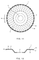
- an outer edge region of the base 1 of the diamond disc may be flat and an extending portion 1D may be formed in the outer edge region to be rounded and to protrude only backward.
- the diamond grains 2 may be arranged on the outer peripheral region of the base 1 including the extending portion 1D.
- the diamond grains 2 may be arranged to the extending portion 1D continuously or intermittently as shown in Fig. 11. With such a structure, the diamond disc is capable of performing cutting as well as grinding.
- an arrow R indicates the rotational direction of the diamond disc.
- the diamond grains 2 may be omitted in the disc surface 1A and an extending portion 1D protruding forward and backward may be formed.
- Such a diamond disc is configured exclusively for cutting in a limited sense or groove forming.
- the diamond disc configured exclusively for cutting in a limited sense or groove forming may be constructed such that the base 1 is entirely formed by a flat circular plate.
- an arrow R represents the rotational direction of the diamond disc.
- the diamond disc of the present invention is used in grinding of materials to be ground, such as grinding of concrete, stone, tile or steel plate, or peeling of coatings applied to their surfaces.
Landscapes
- Engineering & Computer Science (AREA)
- Mechanical Engineering (AREA)
- Chemical & Material Sciences (AREA)
- Mining & Mineral Resources (AREA)
- Ceramic Engineering (AREA)
- Inorganic Chemistry (AREA)
- Polishing Bodies And Polishing Tools (AREA)
- Polarising Elements (AREA)
- Transition And Organic Metals Composition Catalysts For Addition Polymerization (AREA)
- Steroid Compounds (AREA)
Priority Applications (2)
| Application Number | Priority Date | Filing Date | Title |
|---|---|---|---|
| EP20080005472 EP1944126A1 (de) | 2002-12-19 | 2003-12-18 | Diamantenplatte |
| EP08005544A EP1941972B1 (de) | 2002-12-19 | 2003-12-18 | Diamantenplatte |
Applications Claiming Priority (7)
| Application Number | Priority Date | Filing Date | Title |
|---|---|---|---|
| JP2002367807 | 2002-12-19 | ||
| JP2002367807 | 2002-12-19 | ||
| JP2003142892 | 2003-05-21 | ||
| JP2003142892 | 2003-05-21 | ||
| JP2003285289 | 2003-08-01 | ||
| JP2003285289 | 2003-08-01 | ||
| PCT/JP2003/016210 WO2004056533A1 (ja) | 2002-12-19 | 2003-12-18 | ダイヤディスク |
Related Child Applications (2)
| Application Number | Title | Priority Date | Filing Date |
|---|---|---|---|
| EP20080005472 Division EP1944126A1 (de) | 2002-12-19 | 2003-12-18 | Diamantenplatte |
| EP08005544A Division EP1941972B1 (de) | 2002-12-19 | 2003-12-18 | Diamantenplatte |
Publications (2)
| Publication Number | Publication Date |
|---|---|
| EP1595645A1 true EP1595645A1 (de) | 2005-11-16 |
| EP1595645A4 EP1595645A4 (de) | 2007-09-12 |
Family
ID=32685826
Family Applications (2)
| Application Number | Title | Priority Date | Filing Date |
|---|---|---|---|
| EP03780867A Withdrawn EP1595645A4 (de) | 2002-12-19 | 2003-12-18 | Diamantscheibe |
| EP08005544A Expired - Lifetime EP1941972B1 (de) | 2002-12-19 | 2003-12-18 | Diamantenplatte |
Family Applications After (1)
| Application Number | Title | Priority Date | Filing Date |
|---|---|---|---|
| EP08005544A Expired - Lifetime EP1941972B1 (de) | 2002-12-19 | 2003-12-18 | Diamantenplatte |
Country Status (11)
| Country | Link |
|---|---|
| US (1) | US7357705B2 (de) |
| EP (2) | EP1595645A4 (de) |
| JP (2) | JP4335872B2 (de) |
| KR (1) | KR100635553B1 (de) |
| AT (1) | ATE441502T1 (de) |
| AU (3) | AU2003289412B2 (de) |
| BR (1) | BR0316766A (de) |
| CA (3) | CA2509910C (de) |
| DE (1) | DE60329133D1 (de) |
| TW (1) | TWI238753B (de) |
| WO (1) | WO2004056533A1 (de) |
Cited By (12)
| Publication number | Priority date | Publication date | Assignee | Title |
|---|---|---|---|---|
| WO2009075004A1 (en) * | 2007-12-12 | 2009-06-18 | Ghines S.R.L. | Abrasive tool |
| EP2286959A3 (de) * | 2009-08-22 | 2011-03-16 | August Rüggeberg GmbH & Co. KG | Schrupp-Schleif-Werkzeug |
| WO2011072919A1 (de) * | 2009-12-17 | 2011-06-23 | Robert Bosch Gmbh | Werkzeug für eine handwerkzeugmaschine |
| CN101394977B (zh) * | 2006-02-28 | 2011-12-21 | 二和金刚石工业株式会社 | 框锯的切削刀片和具有该切削刀片的框锯 |
| EP2094423A4 (de) * | 2006-11-16 | 2012-08-29 | Shinhan Diamond Ind Co Ltd | Diamantwerkzeug |
| ITRM20110173A1 (it) * | 2011-04-06 | 2012-10-07 | Mattia Mauro Di | Utensile. |
| WO2013029868A1 (de) * | 2011-09-02 | 2013-03-07 | Robert Bosch Gmbh | Schleif- bzw. schneidwerkzeug für eine werkzeugmaschine mit drehantrieb |
| CN103273408A (zh) * | 2013-05-23 | 2013-09-04 | 芜湖得瑞精密机械有限公司 | 一种轮胎断面切割机 |
| WO2014131823A1 (de) * | 2013-02-27 | 2014-09-04 | Tutech Innovations Gmbh | Verfahren zum herstellen von einfach oder mehrfach gekurvten konturen sowie ein entsprechendes werkzeug |
| EP3013920A1 (de) * | 2013-06-28 | 2016-05-04 | Robert Bosch GmbH | Schleifmittel |
| RU2657669C2 (ru) * | 2016-05-20 | 2018-06-14 | Федеральное государственное бюджетное образовательное учреждение высшего профессионального образования "Владимирский государственный университет имени Александра Григорьевича и Николая Григорьевича Столетовых" (ВлГУ) | Плоский шлифовальный круг и способ его изготовления |
| WO2019025883A1 (en) * | 2017-07-31 | 2019-02-07 | 3M Innovative Properties Company | VARIABLE ABRASIVE DISTRIBUTION FLOOR MAT |
Families Citing this family (31)
| Publication number | Priority date | Publication date | Assignee | Title |
|---|---|---|---|---|
| USD538312S1 (en) | 2005-09-16 | 2007-03-13 | 3M Innovative Properties Company | Abrasive article with holes |
| USD538313S1 (en) | 2005-09-16 | 2007-03-13 | 3M Innovative Properties Company | Abrasive article with holes |
| USD536714S1 (en) * | 2005-09-16 | 2007-02-13 | 3M Innovative Properties Company | Abrasive article with holes |
| USD541317S1 (en) | 2006-02-01 | 2007-04-24 | 3M Innovative Properties Company | Abrasive article with holes |
| USD543562S1 (en) | 2006-02-01 | 2007-05-29 | 3M Innovative Properties Company | Abrasive article with holes |
| US7833088B1 (en) | 2006-08-11 | 2010-11-16 | Studer Ronald M | Construction method and tool supporting said method |
| KR100804049B1 (ko) * | 2006-11-16 | 2008-02-18 | 신한다이아몬드공업 주식회사 | 다이아몬드 공구 및 다이아몬드 공구의 세그먼트 제조방법 |
| KR100753317B1 (ko) * | 2006-11-16 | 2007-08-29 | 신한다이아몬드공업 주식회사 | 다이아몬드 공구 |
| KR100811751B1 (ko) * | 2006-11-21 | 2008-03-11 | (주)인성다이아몬드 | 연마휠 |
| US7690970B2 (en) * | 2007-01-19 | 2010-04-06 | Epoxy-Tech, Inc. | Abrasive preparation device with an improved abrasion element assembly |
| KR100813769B1 (ko) * | 2007-01-24 | 2008-03-13 | 강식성 | 표면 연마용 휠 |
| KR100839518B1 (ko) * | 2007-01-26 | 2008-06-19 | 신한다이아몬드공업 주식회사 | 다이아몬드 공구 및 그 제조방법 |
| US7959694B2 (en) * | 2007-03-05 | 2011-06-14 | 3M Innovative Properties Company | Laser cut abrasive article, and methods |
| US8080072B2 (en) | 2007-03-05 | 2011-12-20 | 3M Innovative Properties Company | Abrasive article with supersize coating, and methods |
| KR100877707B1 (ko) | 2007-07-27 | 2009-01-07 | 강식성 | 표면 연마용 휠 |
| USD586370S1 (en) * | 2007-08-09 | 2009-02-10 | 3M Innovative Properties Company | Random hole abrasive disc |
| KR101024674B1 (ko) * | 2007-12-28 | 2011-03-25 | 신한다이아몬드공업 주식회사 | 소수성 절삭공구 및 그제조방법 |
| US20100326416A1 (en) * | 2008-03-19 | 2010-12-30 | Ronald Schwarz | High speed abrasive cutting blade with simulated teeth |
| USD645065S1 (en) * | 2008-05-22 | 2011-09-13 | 3M Innovative Properties Company | Abrasive article with holes |
| JP5686338B2 (ja) | 2009-12-22 | 2015-03-18 | 日鉄住金防蝕株式会社 | 回転研削工具およびその製造方法 |
| US9193610B2 (en) | 2011-08-10 | 2015-11-24 | Ecolab USA, Inc. | Synergistic interaction of weak cation exchange resin and magnesium oxide |
| KR101327907B1 (ko) * | 2011-08-24 | 2013-11-13 | 새솔다이아몬드공업 주식회사 | 가공팁 |
| BR112014016015B1 (pt) | 2011-12-31 | 2020-12-29 | Saint-Gobain Abrasives, Inc. | artigo abrasivo com distribuição não uniforme de aberturas |
| WO2013161849A1 (ja) | 2012-04-24 | 2013-10-31 | 株式会社東京精密 | ダイシングブレード |
| CN104364884B (zh) * | 2012-06-15 | 2017-06-23 | 株式会社东京精密 | 切割装置以及切割方法 |
| DE102012214915A1 (de) * | 2012-08-22 | 2014-03-20 | Robert Bosch Gmbh | Werkzeugeinheit |
| CN102873645B (zh) * | 2012-10-08 | 2016-06-01 | 上海磐锋超硬工具科技有限公司 | 一种切磨片 |
| JP6356404B2 (ja) * | 2012-10-31 | 2018-07-11 | 豊田バンモップス株式会社 | 電着ホイール及び電着ホイールの製造方法 |
| TWI589404B (zh) * | 2013-06-28 | 2017-07-01 | 聖高拜磨料有限公司 | 基於向日葵圖案之經塗佈的研磨製品 |
| WO2021034790A1 (en) | 2019-08-19 | 2021-02-25 | Diamabrush Llc | Floor polishing apparatus |
| KR102296729B1 (ko) * | 2021-06-03 | 2021-08-31 | 빈인선 | 밀착 효율이 높은 전동연마기 탈부착용 연마디스크 |
Family Cites Families (27)
| Publication number | Priority date | Publication date | Assignee | Title |
|---|---|---|---|---|
| JPS5540120B2 (de) * | 1974-11-30 | 1980-10-15 | ||
| JPS58171266A (ja) * | 1982-03-31 | 1983-10-07 | Chihiro Tsukamoto | 絵付研磨体の製法 |
| JPS60242975A (ja) * | 1984-05-14 | 1985-12-02 | Kanebo Ltd | 平面研磨装置 |
| JPS6246553U (de) * | 1985-09-09 | 1987-03-20 | ||
| JPH0164365U (de) * | 1987-06-29 | 1989-04-25 | ||
| AU3867989A (en) * | 1988-06-30 | 1990-01-23 | Diabrasive International Ltd. | Abrasive product with reduced particle concentration |
| JPH0290058U (de) * | 1988-12-27 | 1990-07-17 | ||
| US5206499A (en) | 1989-06-22 | 1993-04-27 | Northrop Corporation | Strapdown stellar sensor and holographic multiple field of view telescope therefor |
| US5496208A (en) * | 1989-12-20 | 1996-03-05 | Neff; Charles E. | Grinding wheel |
| JPH06126728A (ja) * | 1992-10-16 | 1994-05-10 | Asahi Chem Ind Co Ltd | 無機質系建材の切削方法 |
| DE4243017A1 (de) | 1992-12-18 | 1994-06-23 | Hilti Ag | Scheibenförmiges Schleifwerkzeug |
| JPH06339863A (ja) | 1993-02-25 | 1994-12-13 | Tone Corp | 鋳物粗仕上げ用研削砥石 |
| JP3069831B2 (ja) * | 1994-12-16 | 2000-07-24 | 株式会社利根 | 鋳物切断用カッター |
| KR0158750B1 (ko) * | 1995-06-09 | 1999-01-15 | 김수광 | 연마용 시트 |
| US6039641A (en) * | 1997-04-04 | 2000-03-21 | Sung; Chien-Min | Brazed diamond tools by infiltration |
| JP3108045B2 (ja) | 1997-10-06 | 2000-11-13 | 株式会社マミ | 研削手工具 |
| KR100285413B1 (ko) * | 1998-09-03 | 2001-04-02 | 김세광 | 림타입의다이아몬드브레이드 |
| JP4269018B2 (ja) | 1998-10-09 | 2009-05-27 | 三京ダイヤモンド工業株式会社 | ダイヤモンドカッターの製造方法及びダイヤモンドカッター |
| JP2001219376A (ja) * | 2000-02-07 | 2001-08-14 | Mitsubishi Materials Corp | 電着砥石 |
| JP2001157967A (ja) * | 1999-11-29 | 2001-06-12 | Mitsubishi Materials Corp | 単層砥石 |
| US6287184B1 (en) * | 1999-10-01 | 2001-09-11 | 3M Innovative Properties Company | Marked abrasive article |
| US6439986B1 (en) * | 1999-10-12 | 2002-08-27 | Hunatech Co., Ltd. | Conditioner for polishing pad and method for manufacturing the same |
| WO2001076821A1 (en) * | 2000-04-05 | 2001-10-18 | Sankyo Diamond Industrial Co., Ltd. | Grinding stone |
| JP3791610B2 (ja) * | 2000-09-13 | 2006-06-28 | 株式会社アライドマテリアル | 鏡面加工用超砥粒ホイール |
| CN100361786C (zh) * | 2000-12-21 | 2008-01-16 | 新日本制铁株式会社 | Cmp调节器、用于cmp调节器的硬质磨粒的排列方法以及cmp调节器的制造方法 |
| JP2002192470A (ja) * | 2000-12-25 | 2002-07-10 | Goei Seisakusho:Kk | 砥石工具 |
| US6599177B2 (en) * | 2001-06-25 | 2003-07-29 | Saint-Gobain Abrasives Technology Company | Coated abrasives with indicia |
-
2003
- 2003-12-12 TW TW092135145A patent/TWI238753B/zh not_active IP Right Cessation
- 2003-12-18 US US10/539,857 patent/US7357705B2/en not_active Expired - Fee Related
- 2003-12-18 JP JP2005502616A patent/JP4335872B2/ja not_active Expired - Fee Related
- 2003-12-18 EP EP03780867A patent/EP1595645A4/de not_active Withdrawn
- 2003-12-18 DE DE60329133T patent/DE60329133D1/de not_active Expired - Lifetime
- 2003-12-18 WO PCT/JP2003/016210 patent/WO2004056533A1/ja not_active Ceased
- 2003-12-18 KR KR1020057010930A patent/KR100635553B1/ko not_active Expired - Fee Related
- 2003-12-18 CA CA002509910A patent/CA2509910C/en not_active Expired - Fee Related
- 2003-12-18 BR BR0316766-6A patent/BR0316766A/pt not_active IP Right Cessation
- 2003-12-18 CA CA002632775A patent/CA2632775A1/en not_active Abandoned
- 2003-12-18 CA CA002632701A patent/CA2632701A1/en not_active Abandoned
- 2003-12-18 AT AT08005544T patent/ATE441502T1/de not_active IP Right Cessation
- 2003-12-18 AU AU2003289412A patent/AU2003289412B2/en not_active Ceased
- 2003-12-18 EP EP08005544A patent/EP1941972B1/de not_active Expired - Lifetime
-
2007
- 2007-09-12 AU AU2007216741A patent/AU2007216741B2/en not_active Ceased
-
2008
- 2008-08-21 JP JP2008213207A patent/JP2009006478A/ja active Pending
-
2009
- 2009-03-02 AU AU2009200815A patent/AU2009200815B8/en not_active Expired - Fee Related
Cited By (19)
| Publication number | Priority date | Publication date | Assignee | Title |
|---|---|---|---|---|
| CN101394977B (zh) * | 2006-02-28 | 2011-12-21 | 二和金刚石工业株式会社 | 框锯的切削刀片和具有该切削刀片的框锯 |
| EP2094423A4 (de) * | 2006-11-16 | 2012-08-29 | Shinhan Diamond Ind Co Ltd | Diamantwerkzeug |
| CN101896315B (zh) * | 2007-12-12 | 2013-01-23 | S·吉内利 | 研磨工具 |
| WO2009075004A1 (en) * | 2007-12-12 | 2009-06-18 | Ghines S.R.L. | Abrasive tool |
| EP2286959A3 (de) * | 2009-08-22 | 2011-03-16 | August Rüggeberg GmbH & Co. KG | Schrupp-Schleif-Werkzeug |
| CN101992429A (zh) * | 2009-08-22 | 2011-03-30 | 奥古斯特吕格贝格有限及两合公司 | 粗磨具 |
| CN101992429B (zh) * | 2009-08-22 | 2015-04-08 | 奥古斯特吕格贝格有限及两合公司 | 粗磨具 |
| WO2011072919A1 (de) * | 2009-12-17 | 2011-06-23 | Robert Bosch Gmbh | Werkzeug für eine handwerkzeugmaschine |
| CN102655982A (zh) * | 2009-12-17 | 2012-09-05 | 罗伯特·博世有限公司 | 用于手持式工具机的刀具 |
| WO2012137143A1 (en) * | 2011-04-06 | 2012-10-11 | Mauro Di Mattia | Surface machining tool |
| ITRM20110173A1 (it) * | 2011-04-06 | 2012-10-07 | Mattia Mauro Di | Utensile. |
| WO2013029868A1 (de) * | 2011-09-02 | 2013-03-07 | Robert Bosch Gmbh | Schleif- bzw. schneidwerkzeug für eine werkzeugmaschine mit drehantrieb |
| WO2014131823A1 (de) * | 2013-02-27 | 2014-09-04 | Tutech Innovations Gmbh | Verfahren zum herstellen von einfach oder mehrfach gekurvten konturen sowie ein entsprechendes werkzeug |
| CN103273408A (zh) * | 2013-05-23 | 2013-09-04 | 芜湖得瑞精密机械有限公司 | 一种轮胎断面切割机 |
| CN103273408B (zh) * | 2013-05-23 | 2016-05-25 | 芜湖得瑞精密机械有限公司 | 一种轮胎断面切割机 |
| EP3013920A1 (de) * | 2013-06-28 | 2016-05-04 | Robert Bosch GmbH | Schleifmittel |
| RU2657669C2 (ru) * | 2016-05-20 | 2018-06-14 | Федеральное государственное бюджетное образовательное учреждение высшего профессионального образования "Владимирский государственный университет имени Александра Григорьевича и Николая Григорьевича Столетовых" (ВлГУ) | Плоский шлифовальный круг и способ его изготовления |
| WO2019025883A1 (en) * | 2017-07-31 | 2019-02-07 | 3M Innovative Properties Company | VARIABLE ABRASIVE DISTRIBUTION FLOOR MAT |
| US11806838B2 (en) | 2017-07-31 | 2023-11-07 | 3M Innovative Properties Company | Floor pad with variable abrasive distribution |
Also Published As
| Publication number | Publication date |
|---|---|
| CA2509910C (en) | 2009-04-14 |
| EP1595645A4 (de) | 2007-09-12 |
| JP4335872B2 (ja) | 2009-09-30 |
| TWI238753B (en) | 2005-09-01 |
| AU2009200815A1 (en) | 2009-03-19 |
| AU2007216741B2 (en) | 2009-03-26 |
| JPWO2004056533A1 (ja) | 2006-04-20 |
| ATE441502T1 (de) | 2009-09-15 |
| AU2009200815B2 (en) | 2009-11-05 |
| CA2632775A1 (en) | 2004-07-08 |
| BR0316766A (pt) | 2005-11-01 |
| AU2003289412A1 (en) | 2004-07-14 |
| US20060160481A1 (en) | 2006-07-20 |
| US7357705B2 (en) | 2008-04-15 |
| AU2007216741A1 (en) | 2007-10-04 |
| DE60329133D1 (de) | 2009-10-15 |
| CA2509910A1 (en) | 2004-07-08 |
| WO2004056533A1 (ja) | 2004-07-08 |
| AU2009200815B8 (en) | 2009-11-19 |
| KR100635553B1 (ko) | 2006-10-18 |
| AU2003289412B2 (en) | 2007-10-25 |
| CA2632701A1 (en) | 2004-07-08 |
| EP1941972A1 (de) | 2008-07-09 |
| TW200410788A (en) | 2004-07-01 |
| EP1941972B1 (de) | 2009-09-02 |
| KR20050085667A (ko) | 2005-08-29 |
| JP2009006478A (ja) | 2009-01-15 |
Similar Documents
| Publication | Publication Date | Title |
|---|---|---|
| US7357705B2 (en) | Diamond disk | |
| US6926583B2 (en) | Grinding wheel | |
| JPH06210571A (ja) | ディスク状研削工具 | |
| KR100804048B1 (ko) | 다이아몬드 공구 | |
| EP1944126A1 (de) | Diamantenplatte | |
| JP4084864B2 (ja) | カッティングソー | |
| JP4215570B2 (ja) | ドレッサ | |
| JPH11156729A (ja) | チップ交換可能な砥石車 | |
| RU2306218C2 (ru) | Алмазный диск | |
| JP2001293661A (ja) | 回転円盤砥石 | |
| JPH11207633A (ja) | ダイヤモンドブレード | |
| JPH0760648A (ja) | 精密研削切断砥石 | |
| JPH1199478A (ja) | ダイヤモンド切断砥石 | |
| JP2009136927A (ja) | 研削砥石 | |
| JPH074099Y2 (ja) | 円鋸の刃部の構造 | |
| JP3035486B2 (ja) | ダイヤモンドドレッサ | |
| JPH0730250Y2 (ja) | 円鋸の刃部の構造 | |
| JP2004066383A (ja) | 研削用ダイヤディスク | |
| CN1732069A (zh) | 金刚石盘片 | |
| JP2008142795A (ja) | ソーブレード | |
| JPS60232875A (ja) | 切断鋸 | |
| JPH075982Y2 (ja) | セグメント型ダイヤモンドブレード | |
| HK1085156A (en) | Diamond disk | |
| JP2006015446A (ja) | 切断用超砥粒工具 | |
| JPH0653026U (ja) | 円鋸の刃部の構造 |
Legal Events
| Date | Code | Title | Description |
|---|---|---|---|
| PUAI | Public reference made under article 153(3) epc to a published international application that has entered the european phase |
Free format text: ORIGINAL CODE: 0009012 |
|
| 17P | Request for examination filed |
Effective date: 20050713 |
|
| AK | Designated contracting states |
Kind code of ref document: A1 Designated state(s): AT BE BG CH CY CZ DE DK EE ES FI FR GB GR HU IE IT LI LU MC NL PT RO SE SI SK TR |
|
| AX | Request for extension of the european patent |
Extension state: AL LT LV MK |
|
| DAX | Request for extension of the european patent (deleted) | ||
| RIC1 | Information provided on ipc code assigned before grant |
Ipc: B24D 5/12 20060101ALI20070430BHEP Ipc: B24D 3/10 20060101ALI20070430BHEP Ipc: B24D 7/06 20060101AFI20070430BHEP |
|
| A4 | Supplementary search report drawn up and despatched |
Effective date: 20070816 |
|
| 17Q | First examination report despatched |
Effective date: 20080129 |
|
| GRAP | Despatch of communication of intention to grant a patent |
Free format text: ORIGINAL CODE: EPIDOSNIGR1 |
|
| RTI1 | Title (correction) |
Free format text: DIAMOND DISC |
|
| STAA | Information on the status of an ep patent application or granted ep patent |
Free format text: STATUS: THE APPLICATION IS DEEMED TO BE WITHDRAWN |
|
| 18D | Application deemed to be withdrawn |
Effective date: 20100302 |