EP1582253A2 - Ein Rührer, eine Kreislaufwaschvorrichtung verbunden mit dem Rührer, und ein Kreislaufmischsystem, das die Kreislaufwaschvorrichtung enthält - Google Patents
Ein Rührer, eine Kreislaufwaschvorrichtung verbunden mit dem Rührer, und ein Kreislaufmischsystem, das die Kreislaufwaschvorrichtung enthält Download PDFInfo
- Publication number
- EP1582253A2 EP1582253A2 EP05290666A EP05290666A EP1582253A2 EP 1582253 A2 EP1582253 A2 EP 1582253A2 EP 05290666 A EP05290666 A EP 05290666A EP 05290666 A EP05290666 A EP 05290666A EP 1582253 A2 EP1582253 A2 EP 1582253A2
- Authority
- EP
- European Patent Office
- Prior art keywords
- paddle blade
- flat paddle
- vessel
- agitator
- agitating
- Prior art date
- Legal status (The legal status is an assumption and is not a legal conclusion. Google has not performed a legal analysis and makes no representation as to the accuracy of the status listed.)
- Granted
Links
- 238000004140 cleaning Methods 0.000 title claims description 139
- 239000012530 fluid Substances 0.000 claims abstract description 43
- 239000006185 dispersion Substances 0.000 claims description 84
- 239000007788 liquid Substances 0.000 claims description 81
- 239000000049 pigment Substances 0.000 claims description 81
- 238000000227 grinding Methods 0.000 claims description 26
- 239000002826 coolant Substances 0.000 claims description 14
- 239000011324 bead Substances 0.000 claims description 13
- 239000002699 waste material Substances 0.000 claims description 12
- 230000002093 peripheral effect Effects 0.000 claims description 11
- 239000011164 primary particle Substances 0.000 claims description 5
- 239000011163 secondary particle Substances 0.000 claims description 3
- 238000004891 communication Methods 0.000 claims description 2
- 238000007599 discharging Methods 0.000 claims description 2
- 238000001816 cooling Methods 0.000 abstract description 5
- 230000009471 action Effects 0.000 description 9
- 238000000034 method Methods 0.000 description 8
- 230000007246 mechanism Effects 0.000 description 6
- 230000005540 biological transmission Effects 0.000 description 5
- 238000004519 manufacturing process Methods 0.000 description 5
- 238000002156 mixing Methods 0.000 description 5
- 230000008569 process Effects 0.000 description 5
- XLYOFNOQVPJJNP-UHFFFAOYSA-N water Substances O XLYOFNOQVPJJNP-UHFFFAOYSA-N 0.000 description 4
- 239000011248 coating agent Substances 0.000 description 3
- 239000008199 coating composition Substances 0.000 description 3
- 238000000576 coating method Methods 0.000 description 3
- 230000000694 effects Effects 0.000 description 3
- 239000011521 glass Substances 0.000 description 3
- 239000000463 material Substances 0.000 description 3
- 239000000203 mixture Substances 0.000 description 3
- 229920006362 Teflon® Polymers 0.000 description 2
- 238000004040 coloring Methods 0.000 description 2
- 230000006866 deterioration Effects 0.000 description 2
- 230000005484 gravity Effects 0.000 description 2
- 239000011347 resin Substances 0.000 description 2
- 229920005989 resin Polymers 0.000 description 2
- 239000002904 solvent Substances 0.000 description 2
- 238000012546 transfer Methods 0.000 description 2
- YCKRFDGAMUMZLT-UHFFFAOYSA-N Fluorine atom Chemical compound [F] YCKRFDGAMUMZLT-UHFFFAOYSA-N 0.000 description 1
- 239000000853 adhesive Substances 0.000 description 1
- 230000001070 adhesive effect Effects 0.000 description 1
- 238000013019 agitation Methods 0.000 description 1
- 239000003086 colorant Substances 0.000 description 1
- 230000008602 contraction Effects 0.000 description 1
- 238000001514 detection method Methods 0.000 description 1
- 229910052731 fluorine Inorganic materials 0.000 description 1
- 239000011737 fluorine Substances 0.000 description 1
- 238000010438 heat treatment Methods 0.000 description 1
- 239000000976 ink Substances 0.000 description 1
- 238000009434 installation Methods 0.000 description 1
- 239000003960 organic solvent Substances 0.000 description 1
- 238000011176 pooling Methods 0.000 description 1
- 238000012545 processing Methods 0.000 description 1
- 239000002994 raw material Substances 0.000 description 1
- 238000011160 research Methods 0.000 description 1
- 238000007789 sealing Methods 0.000 description 1
- 238000010008 shearing Methods 0.000 description 1
- 229910001220 stainless steel Inorganic materials 0.000 description 1
- 239000010935 stainless steel Substances 0.000 description 1
- 230000003068 static effect Effects 0.000 description 1
- 230000009974 thixotropic effect Effects 0.000 description 1
- 239000002966 varnish Substances 0.000 description 1
Images


Classifications
-
- B—PERFORMING OPERATIONS; TRANSPORTING
- B01—PHYSICAL OR CHEMICAL PROCESSES OR APPARATUS IN GENERAL
- B01F—MIXING, e.g. DISSOLVING, EMULSIFYING OR DISPERSING
- B01F25/00—Flow mixers; Mixers for falling materials, e.g. solid particles
- B01F25/50—Circulation mixers, e.g. wherein at least part of the mixture is discharged from and reintroduced into a receptacle
- B01F25/52—Circulation mixers, e.g. wherein at least part of the mixture is discharged from and reintroduced into a receptacle with a rotary stirrer in the recirculation tube
-
- B—PERFORMING OPERATIONS; TRANSPORTING
- B01—PHYSICAL OR CHEMICAL PROCESSES OR APPARATUS IN GENERAL
- B01F—MIXING, e.g. DISSOLVING, EMULSIFYING OR DISPERSING
- B01F27/00—Mixers with rotary stirring devices in fixed receptacles; Kneaders
- B01F27/05—Stirrers
- B01F27/07—Stirrers characterised by their mounting on the shaft
- B01F27/072—Stirrers characterised by their mounting on the shaft characterised by the disposition of the stirrers with respect to the rotating axis
- B01F27/0725—Stirrers characterised by their mounting on the shaft characterised by the disposition of the stirrers with respect to the rotating axis on the free end of the rotating axis
-
- B—PERFORMING OPERATIONS; TRANSPORTING
- B01—PHYSICAL OR CHEMICAL PROCESSES OR APPARATUS IN GENERAL
- B01F—MIXING, e.g. DISSOLVING, EMULSIFYING OR DISPERSING
- B01F27/00—Mixers with rotary stirring devices in fixed receptacles; Kneaders
- B01F27/80—Mixers with rotary stirring devices in fixed receptacles; Kneaders with stirrers rotating about a substantially vertical axis
- B01F27/90—Mixers with rotary stirring devices in fixed receptacles; Kneaders with stirrers rotating about a substantially vertical axis with paddles or arms
- B01F27/906—Mixers with rotary stirring devices in fixed receptacles; Kneaders with stirrers rotating about a substantially vertical axis with paddles or arms with fixed axis
-
- B—PERFORMING OPERATIONS; TRANSPORTING
- B01—PHYSICAL OR CHEMICAL PROCESSES OR APPARATUS IN GENERAL
- B01F—MIXING, e.g. DISSOLVING, EMULSIFYING OR DISPERSING
- B01F33/00—Other mixers; Mixing plants; Combinations of mixers
- B01F33/80—Mixing plants; Combinations of mixers
- B01F33/83—Mixing plants specially adapted for mixing in combination with disintegrating operations
- B01F33/831—Devices with consecutive working receptacles, e.g. with two intermeshing tools in one of the receptacles
-
- B—PERFORMING OPERATIONS; TRANSPORTING
- B01—PHYSICAL OR CHEMICAL PROCESSES OR APPARATUS IN GENERAL
- B01F—MIXING, e.g. DISSOLVING, EMULSIFYING OR DISPERSING
- B01F35/00—Accessories for mixers; Auxiliary operations or auxiliary devices; Parts or details of general application
- B01F35/10—Maintenance of mixers
- B01F35/145—Washing or cleaning mixers not provided for in other groups in this subclass; Inhibiting build-up of material on machine parts using other means
- B01F35/1452—Washing or cleaning mixers not provided for in other groups in this subclass; Inhibiting build-up of material on machine parts using other means using fluids
- B01F35/1453—Washing or cleaning mixers not provided for in other groups in this subclass; Inhibiting build-up of material on machine parts using other means using fluids by means of jets of fluid, e.g. air
-
- B—PERFORMING OPERATIONS; TRANSPORTING
- B01—PHYSICAL OR CHEMICAL PROCESSES OR APPARATUS IN GENERAL
- B01F—MIXING, e.g. DISSOLVING, EMULSIFYING OR DISPERSING
- B01F35/00—Accessories for mixers; Auxiliary operations or auxiliary devices; Parts or details of general application
- B01F35/90—Heating or cooling systems
- B01F35/92—Heating or cooling systems for heating the outside of the receptacle, e.g. heated jackets or burners
-
- B—PERFORMING OPERATIONS; TRANSPORTING
- B01—PHYSICAL OR CHEMICAL PROCESSES OR APPARATUS IN GENERAL
- B01F—MIXING, e.g. DISSOLVING, EMULSIFYING OR DISPERSING
- B01F35/00—Accessories for mixers; Auxiliary operations or auxiliary devices; Parts or details of general application
- B01F35/90—Heating or cooling systems
- B01F35/95—Heating or cooling systems using heated or cooled stirrers
-
- B—PERFORMING OPERATIONS; TRANSPORTING
- B01—PHYSICAL OR CHEMICAL PROCESSES OR APPARATUS IN GENERAL
- B01F—MIXING, e.g. DISSOLVING, EMULSIFYING OR DISPERSING
- B01F35/00—Accessories for mixers; Auxiliary operations or auxiliary devices; Parts or details of general application
- B01F35/90—Heating or cooling systems
- B01F2035/98—Cooling
-
- B—PERFORMING OPERATIONS; TRANSPORTING
- B01—PHYSICAL OR CHEMICAL PROCESSES OR APPARATUS IN GENERAL
- B01F—MIXING, e.g. DISSOLVING, EMULSIFYING OR DISPERSING
- B01F27/00—Mixers with rotary stirring devices in fixed receptacles; Kneaders
- B01F27/05—Stirrers
- B01F27/07—Stirrers characterised by their mounting on the shaft
- B01F27/072—Stirrers characterised by their mounting on the shaft characterised by the disposition of the stirrers with respect to the rotating axis
- B01F27/0721—Stirrers characterised by their mounting on the shaft characterised by the disposition of the stirrers with respect to the rotating axis parallel with respect to the rotating axis
-
- B—PERFORMING OPERATIONS; TRANSPORTING
- B01—PHYSICAL OR CHEMICAL PROCESSES OR APPARATUS IN GENERAL
- B01F—MIXING, e.g. DISSOLVING, EMULSIFYING OR DISPERSING
- B01F27/00—Mixers with rotary stirring devices in fixed receptacles; Kneaders
- B01F27/05—Stirrers
- B01F27/07—Stirrers characterised by their mounting on the shaft
- B01F27/072—Stirrers characterised by their mounting on the shaft characterised by the disposition of the stirrers with respect to the rotating axis
- B01F27/0724—Stirrers characterised by their mounting on the shaft characterised by the disposition of the stirrers with respect to the rotating axis directly mounted on the rotating axis
-
- B—PERFORMING OPERATIONS; TRANSPORTING
- B01—PHYSICAL OR CHEMICAL PROCESSES OR APPARATUS IN GENERAL
- B01F—MIXING, e.g. DISSOLVING, EMULSIFYING OR DISPERSING
- B01F27/00—Mixers with rotary stirring devices in fixed receptacles; Kneaders
- B01F27/05—Stirrers
- B01F27/11—Stirrers characterised by the configuration of the stirrers
- B01F27/112—Stirrers characterised by the configuration of the stirrers with arms, paddles, vanes or blades
- B01F27/1122—Stirrers characterised by the configuration of the stirrers with arms, paddles, vanes or blades anchor-shaped
-
- B—PERFORMING OPERATIONS; TRANSPORTING
- B01—PHYSICAL OR CHEMICAL PROCESSES OR APPARATUS IN GENERAL
- B01F—MIXING, e.g. DISSOLVING, EMULSIFYING OR DISPERSING
- B01F27/00—Mixers with rotary stirring devices in fixed receptacles; Kneaders
- B01F27/05—Stirrers
- B01F27/11—Stirrers characterised by the configuration of the stirrers
- B01F27/112—Stirrers characterised by the configuration of the stirrers with arms, paddles, vanes or blades
- B01F27/1125—Stirrers characterised by the configuration of the stirrers with arms, paddles, vanes or blades with vanes or blades extending parallel or oblique to the stirrer axis
Definitions
- An agitator An agitator, a circulatory cleaning device attached to the agitator, and a circulatory line system comprising the circulatory cleaning device
- the present invention relates to an agitator, a circulatory cleaning device attached to the agitator, and a circulatory line system comprising the circulatory cleaning device.
- pigment pastes are generally prepared by the steps of mixing pigments, resins, organic solvents, and like raw materials in an agitator to prepare a mill base, and then passing this mill base a few times through a bead mill dispersion apparatus or like continuous dispersion apparatus to disperse the pigment.
- the commonly employed pigment dispersion method comprises the steps of feeding an unprocessed pigment paste stored in a feeding vessel to a dispersion apparatus, temporarily storing the pigment paste obtained by dispersing it in the dispersion apparatus in a receiving vessel, returning the pigment paste stored in the receiving vessel to the dispersion apparatus to redisperse it after the completion of the first pigment dispersion process, and returning the pigment paste which has been subjected to the second pigment dispersion process to the feeding vessel to store it, and then repeating these processes a few times.
- the above-mentioned manufacturing process disadvantageously requires two vessels, i.e., feeding vessel and receiving vessel, and operations to switch between these vessels.
- a known technique connects an agitator and a dispersion apparatus via a circulation line to circulate pigment paste between the apparatuses, unifying the feeding vessel and receiving vessel (for example, refer to Japanese Unexamined Patent Publication Nos. 1996-266880 and 2002-306940).
- a known bead mill apparatus (cf. Japanese Unexamined Patent Publication No. 1996-266880, Japanese Examined Patent Publication No. 1994-28745 and Japanese Unexamined Patent Publication No. 2002-204969) having a mechanism which separates pigment paste from a grinding medium by the action of centrifugal force caused by the rotation of a rotor has such advantages that it has a large throughput (flow rate); it requires only one vessel because it allows circulation dispersion; and it does not require a switching operation between a feeding vessel and a receiving vessel because it has only one vessel.
- a double-shafted mixer having a high-speed agitator and a low-speed anchor type agitating blade which removes the pooled mill base off the vessel wall was developed.
- said double-shaft mixer has the problem of high installation cost.
- a small interval between the vessel wall and anchor type agitating blade makes cleaning the mill base by injecting a cleaning solvent difficult, the mixer still has a problem in its ability to be cleaned when the mixer is applied to the production of coating compositions, which requires the frequent replacement of materials.
- the inventors of the present invention have previously improved the constitution of paddle blades and proposed an agitator which can be applied to a circulatory system with a large flow rate, can deal with a variety of fluids, changes in fluid volume, and has an excellent ability to mix and disperse fluids with different viscosities ranging from low to high and cleanability (refer to Japanese Patent No. 3189047).
- a cleaning device ejects a cleaning liquid from a cleaning nozzle connected to a cleaning liquid tank into the agitating vessel (for example, refer to Japanese Patent No. 3189047).
- This cleaning device showers the inner wall of the agitating vessel and the surface of the agitating blade with the cleaning liquid from the cleaning liquid tank via the cleaning nozzle to wash away pigment paste deposited therein.
- the cleaning liquid ejected from the cleaning liquid nozzle into the agitating vessel is immediately drawn out from the bottom of the agitating vessel, collected and recycled.
- the heating generated by the friction between the grinding medium and the rotor or vessel inside a bead mill and the friction within the grinding medium is greater than the cooling provided by the vessel of the bead mill. Consequently, the temperature of the pigment paste increases.
- the pigment paste is sometimes deteriorated by elevated temperatures, and therefore the heat generated by the pigment paste becomes greater as its viscosity increases.
- a first object of the present invention is to provide an agitator with further improvements in its flat paddle blade, and an agitating vessel with the improved agitator previously suggested by the inventors of the present invention to mainly increase the cooling efficiency of the agitator.
- the aforementioned known improved agitator previously proposed by the inventors of the present invention is capable of cleaning the flat paddle blade and the inner wall of an agitating vessel by circulating a cleaning liquid and has a much higher cleanability than the aforementioned known double-shaft mixer because it employs a flat paddle blade, pigment paste deposited on the outermost peripheral surface (flat surface) of the flat paddle blade and the pigment paste deposited on the bottom of the agitating vessel are sometimes a little difficult to scrape off.
- a cleaning liquid is collected in the agitating vessel, and then the flat paddle blade and the inner wall of the agitating vessel is cleaned by rotating the flat paddle blade backwards and forwards. At this time, the cleaning liquid simultaneously cleans the inside of the bead mill apparatus by circulating through the circulatory channel connecting the bead mill apparatus and the agitator.
- the inventors of the present invention have conducted extensive research, and consequently found that in the prior art, including the previously proposed improved agitator, pigment paste deposited on the flat surface around the agitating blade tends to pool during circulation dispersion since the peripheral edge of the agitating blade is a flat surface as shown in the cross section of Fig. 8, which results in lowered dispersibility. They also found that pigment paste readily adheres and deposits on the flat surface of the agitating blade and cannot be sufficiently cleaned by the cleaning liquid ejected from the cleaning nozzle.
- the inventors of the present invention have found that the flow of cleaning liquid fed through a fluid inlet provided in an upper part of the agitating vessel, discharged through a fluid outlet provided in the bottom, and circulated inside the agitator and bead mill apparatus through the circulatory channel of the bead mill apparatus sometimes pools at the bottom of the agitating vessel.
- a second object of the present invention is to provide an agitator with increased cleanability of a paddle blade and an agitating vessel of the agitator.
- a third object of the present invention is to provide a circulatory cleaning device which can reduce the amount of a cleaning liquid used.
- a fourth object of the present invention is to provide a circulatory line system which can reduce the amount of cleaning liquid used and the labor required for cleaning in a system in which an agitator and a dispersion apparatus are connected via a pipe.
- the agitator comprises an agitating vessel which has a fluid inlet in an upper part thereof, a fluid outlet at the bottom, and a cylindrical circumferential configuration; a rotating shaft extending vertically inside the agitating vessel; and a flat paddle blade mounted on said rotating shaft, the flat paddle blade having a bottom flat paddle blade portion which extends outwards from the bottom of the rotating shaft, and oblong upper flat paddle blade portions extending upward from an upper part of each side end of the bottom flat paddle blade portion, the dimensional ratio (b/a) of the blade diameter (b) of the bottom flat paddle blade portion to the inner diameter (a) of the agitating vessel being in the range of from 0.6 to 0.9, the dimensional ratio (d/c) of the height (d) of the upper flat paddle blade portion to the height (c) of the bottom flat paddle blade portion being in the range of from 1 to 4, and a passage to pass a coolant medium through the rotating shaft and the flat paddle blade.
- the agitator further comprises a coolant jacket around the agitating vessel.
- the agitator according to the present invention has an agitating vessel comprising a fluid inlet in an upper part thereof, a fluid outlet at the bottom, and having a cylindrical peripheral configuration; a rotating shaft extending vertically inside the agitating vessel; and a flat paddle blade mounted on said rotating shaft, the flat paddle blade having a bottom flat paddle blade portion which extends outwards from the bottom of the rotating shaft and a oblong upper flat paddle blade portion extending upward from an upper part of each side end of the bottom flat paddle blade portion, the outermost periphery of the flat paddle blade being tapered by two inclined surfaces.
- the outermost periphery of the flat paddle blade has a V-shaped peripheral configuration formed by the two inclined surfaces and each of said inclined surfaces is formed so that the internal angle ( ⁇ 1 ) between a flat surface of the flat paddle blade and the inclined surface is in the range of from 100°to 140°.
- the bottom configuration of the agitating vessel preferably is in the shape of a cone or a truncated cone tapering downwards, and the bottom configuration of the bottom flat paddle blade portion is preferably formed parallel with the bottom of the agitating vessel.
- the bottom conical surface of the agitating vessel preferably has an inclination so that the angle ( ⁇ 2 ) of the surface is 5°-30° from horizontal.
- the dimensional ratio (e/b) of the width (e) of each upper flat paddle blade portion to the blade diameter (b) of the bottom flat paddle blade portion is preferably in the range of from 0.05 to 0.2.
- the circulatory cleaning device is a circulatory cleaning device attached to an agitator for agitating pigment paste, the device comprising a cleaning liquid tank storing a cleaning liquid; a first pump which suctions a liquid in said cleaning liquid tank and feeds the liquid into the agitating vessel; and a second pump having a suction opening connected to an outlet provided at the bottom of the agitating vessel, and a discharge opening connected to an inlet of the cleaning liquid tank by a circulatory cleaning pipeline.
- a first directional control valve which further has a waste fluid tank which receives cleaning waste fluid and switches so that a liquid discharged from the second pump is discharged into the waste fluid tank, is preferably provided in the circulatory cleaning pipeline.
- the circulation dispersion system comprises the above circulatory cleaning device; the above agitator having an agitating blade and agitating vessel; and a dispersion apparatus provided in the circulatory cleaning pipeline for disaggregating pigment aggregates comprising secondary particles into primary particles and dispersing these primary particles in pigment paste, a second directional control valve which switches so that liquid discharged from the second pump is fed to the dispersion apparatus, wherein an outlet of the dispersion apparatus and a inlet of the agitating vessel are connected by a pipeline for circulation dispersion.
- the circulation dispersion system preferably has a product tank in the pipeline for circulation dispersion for receiving pigment paste which has been subjected to the above dispersion process, and a third directional control valve which switches to discharge liquid discharged from the second pump into the product tank .
- the dispersion apparatus of the circulation dispersion system is an annular bead mill which has a vessel having an inlet which supplies pigment paste for dispersing and an outlet which discharges the dispersed pigment paste; and a rotor having a cylindrical outer peripheral surface and disposed inside the vessel to form an annular gap for performing dispersion between itself and the inner wall of the vessel.
- the annular gap comprises a passage through the inside of the rotor to the outlet; that a centrifuge for centrifuging a grinding medium from grinding medium/pigment paste mixture in the passage inside the rotor is provided; and that an opening for circulation for discharging the centrifuged grinding medium into the annular gap is provided in the rotor.
- the centrifuge has a rotary member which centrifuges the grinding medium and said rotary member is an impeller or a rotational disk.
- the rotational drive shaft of the rotor is a hollow shaft and that an outlet communicating with the outlet of the vessel is formed in said hollow shaft. It is preferable that the inlet of the vessel is disposed on one end of the vessel; an approximately cylindrical stator is further disposed approximately on the other end of the vessel inside the rotor; and that a gap constituting a part of the passage is formed between said stator and the rotor.
- a rotational drive shaft of the rotary member is inserted into the hollow shaft of the rotor and a gap constituting a passage leading to the outlet opening is formed between inner circumferential wall of the hollow shaft of the rotor and the rotational drive shaft of the rotary member. It is preferable that the rotational drive shaft of the rotor and the rotational drive shaft of the rotary member are disposed concentrically.
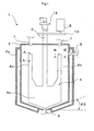
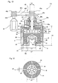
- Fig. 1 is a longitudinal sectional view showing the inner structure of the agitator
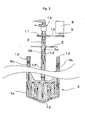
- Fig. 2 is a partial longitudinal sectional view showing the inner structure of the flat paddle blade part of Fig. 1.
- the agitator 1 has an agitating vessel 2; a rotating shaft 3 extending vertically in the inner center of the agitating vessel 2; and a flat paddle blade 4 as an agitating blade mounted on the rotating shaft 3.
- the agitating vessel 2 comprises a fluid inlet 5 in an upper part thereof and a fluid outlet 6 at the bottom. It has a cylindrical circumferential side face and a coolant jacket 2a therearound.
- the coolant jacket can be of a known constitution, and allows a coolant medium such as a coolant water to circulate inside.
- the configuration of the bottom of the agitating vessel 2 is a truncated cone with the narrow portion downwards.
- the agitating vessel 2 comprises cleaning liquid inlets 7, 7 in an upper part thereof.
- the flat paddle blade 4 has a bottom flat paddle blade portion 4a which extends outwards from the bottom of the rotating shaft 3, and oblong upper flat paddle blade portions 4b which extend upward from an upper part of each side end of the bottom flat paddle blade portion 4a.
- the bottom configuration of the bottom flat paddle blade portion 4a is formed by inclined sides parallel to the bottom conical surface of the agitating vessel 2, and has a predetermined clearance between itself and the bottom face of the agitating vessel 2.
- Each upper flat paddle blade portion 4b is set up symmetrically with respect to the rotating shaft 3.
- the rotating shaft 3 is rotationally driven by a drive 8 disposed external to the vessel via a pulley 9, pulley belt 10 and pulley 11, and the rotational drive of the rotation shaft 3 causes the flat paddle blade 4 to pass near the cylindrical inner wall face of the agitating vessel 2 as it rotates.
- a passage 12 is formed to pass a coolant medium through the flat paddle blade 4 via the rotating shaft 3.
- the passage 12 formed in the flat paddle blade 4 is preferably formed in both the bottom flat paddle blade portion 4a and upper flat paddle blade portion 4b.
- a coolant medium which is cooled by a cooler (not shown) to -10°C to 10°C can be used.
- the inner portion of the rotating shaft 3 has a double pipe structure.
- the coolant medium flows, as shown by the arrows in Fig. 2, through the passage 12 formed inside the flat paddle blade 4, through the passage 12 formed by an inner pipe 3a, and is then discharged via the passage 12 formed by an outer pipe 3b of the double pipe.
- a duplex rotary joint 13 corresponding to the double pipe is mounted so that coolant medium can be supplied and discharged from the upper end of the rotating shaft even during rotation of the rotating shaft 3.
- the bottom flat paddle blade portion 4a is configured so that the dimensional ratio (b/a) of the blade diameter b to the inner diameter a of the agitating vessel 2 falls within the range of from 0.6 to 0.9, and preferably 0.6 to 0.8. If the dimensional ratio (b/a) is lower than 0.6, the blade diameter is too small compared to the inner diameter of the agitating vessel 2 and therefore too much pigment paste pools at the vessel wall surface. On the other hand, if the dimensional ratio (b/a) is higher than 0.9, the blade diameter becomes too large compared to the inner diameter of the agitating vessel 2, causing pigment paste to easily short-path.
- the flat paddle blade 4 is designed so that the dimensional ratio (d/c) of the height d of the upper flat paddle blade portion 4b to the height c of the bottom flat paddle blade portion 4a falls within the range of from 1 to 4, and preferably from 1 to 3. If this height dimensional ratio (d/c) is lower than 1, that is, the height d of the upper flat paddle blade portion 4b is too low relative to the height c of the bottom flat paddle blade portion 4a, the driving force required for agitation is too large. This may disadvantageously result in high production costs, accelerated deterioration of machinery due to heavy loads, and increased chances of pigment paste short-pathing.
- the flat paddle blade 4 is designed so that the dimensional ratio (h/a) of overall height, i.e., (d+c), of the flat paddle blade 4 to the inner diameter a of the agitating vessel 2 falls within the range of from 0.8 to 1.5, and preferably from 1.0 to 1.3. If this dimensional ratio (h/a) of height is lower than 0.8, that is, if the overall height h of the flat paddle blade 4 becomes too short relative to the inner diameter a of the agitating vessel 2, pigment paste disadvantageously tends to short-path.
- the oblong upper flat paddle blade portion 4b is a blade whose longest dimension is in the direction of height, and its width e is preferably such that the dimensional ratio (e/b) of the blade width of the upper flat paddle blade portion 4b to the diameter b of the bottom flat paddle blade portion 4a falls within the range of from 0.05 to 0.2, and preferably from 0.06 to 0.15. If the dimensional ratio (e/b) is lower than 0.05, the effect in removing pigment paste in the vicinity of the inner vessel surface is reduced. On the other hand, if it is higher than 0.2, pigment paste tends to short-path.
- the dimensional ratio (c/b) of the height c of the bottom flat paddle blade portion 4a to the blade diameter b of the same is preferably from 0.4 to 1.0, and more preferably from 0.5 to 0.7. If the dimensional ratio (c/b) is lower than 0.4, the agitating effect is lowered. On the other hand, if the dimensional ratio (c/b) is higher than 1.0, the load applied to the apparatus is too large, which accelerates deterioration.
- the flat paddle blade 4 is preferably constituted by a single piece. Moreover, the material(s) constituting the flat paddle blade 4 are not limited and materials which have been used for prior art agitating blades may be used. Stainless steel is especially preferable from the aspect of durability and strength. From the aspect of cleanability, it is preferable that the surface is mirror finished or a Teflon® coating or glass lining is applied to the surface. It should be noted that when the capacity of the agitating vessel 2 is 500 liters, the thickness of the flat paddle blade 4 is 10-30 mm.
- the capacity of the agitating vessel 2 is not particularly limited, but in general ranges from about 2 liters to about 10000 liters.
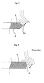
- the flat paddle blade 4 has, as shown in the cross sectional configurations of Figs. 4 and 5, a peripheral portion which is entirely tapered by inclined surfaces 4c, 4c formed two sides and has a V-shaped cross sectional configuration.
- the inclined surfaces 4c, 4c are flat surfaces, but they can also be formed by curving faces as shown in the cross-sectional view of Fig. 6.
- the tip tapered by the inclined surfaces 4c, 4c is illustrated as a sharp point in the examples shown in Figs. 4 and 5, but can be, for example, of rounded U-shaped cross sectional configuration shown in Fig. 6.
- the cross sectional configuration of only the upper flat paddle blade portion 4b is shown in Figs. 4-6, but the case for the bottom flat paddle blade portion 4a is also the same.
- the agitators of the aforementioned first and second embodiments are mainly used incorporated into a circulation dispersion system connected to a dispersion apparatus.
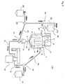
- FIG. 9 A suitable embodiment of such a circulation dispersion system will be described with reference to Figs. 9-11 below. It should be noted that in Fig. 9, the circulation dispersion system 100 comprising the agitator 1, a circulatory cleaning device 80 connected to the agitator 1 by a circulatory cleaning pipeline, and a dispersion apparatus 15 connected to the agitator 1 by a circulation dispersion pipeline 16, and will be described as an example of this embodiment.
- the circulatory cleaning device 80 has a cleaning liquid tank 20 for storing a cleaning liquid such as water and solvent; a first pump 24 which suctions the cleaning liquid from the cleaning liquid tank 20 and provides cleaning liquid inlets 21a, 21a of the agitating vessel 2 with the liquid therein; and a second pump 14 whose suction opening is connected to a fluid outlet 6 provided at the bottom of the agitating vessel 2 and whose discharge opening is connected to a cleaning liquid inlet 20a of the cleaning liquid tank 20 by a circulatory cleaning pipeline 22.
- a cleaning liquid tank 20 for storing a cleaning liquid such as water and solvent
- a first pump 24 which suctions the cleaning liquid from the cleaning liquid tank 20 and provides cleaning liquid inlets 21a, 21a of the agitating vessel 2 with the liquid therein
- a second pump 14 whose suction opening is connected to a fluid outlet 6 provided at the bottom of the agitating vessel 2 and whose discharge opening is connected to a cleaning liquid inlet 20a of the cleaning liquid tank 20 by a circulatory cleaning pipeline 22.
- the cleaning nozzle 21 of the agitating vessel 2 comprises cleaning liquid inlets 21a, 21a, and a cleaning liquid pumped out from the first pump 24 is ejected via the cleaning nozzle 21 at high pressure like a shower at the agitating vessel 2 and the flat paddle blade 4 as an agitating blade.
- the cleaning liquid collected in the agitating vessel 2 is drawn out from the fluid outlet 6 of the agitating vessel 2 by the second pump 14, and is returned to the cleaning liquid tank 20 via the circulatory cleaning pipeline 22.
- the circulatory cleaning device 80 further has a waste fluid tank 25 which receives cleaning waste fluid, and a first directional control valve 23, which switches so that the liquid discharged from the second pump 14 is discharged into the waste fluid tank 25, is provided in the circulatory cleaning pipeline 22.
- a second directional control valve 17 is further provided in the circulatory cleaning pipeline 22.
- the second directional control valve 17 is capable of switching so that liquid discharged from the second pump 14 is fed to the dispersion apparatus 15.
- the outlet of the dispersion apparatus 15 is connected to a fluid inlet 5 of the agitating vessel 2 by a pipeline for circulation dispersion 16.
- a third directional control valve 18 is provided in the pipeline for circulation dispersion 16.
- the third directional control valve 18 is capable of switching so that liquid discharged from the second pump 14 is discharged into a product tank 19.
- the product tank 19 receives pigment paste which has been subjected to the dispersion process.
- the dispersion apparatus 15 there is no particular limitation on the dispersion apparatus 15, and a known pigment dispersion apparatus can be used.
- a bead mill is especially preferably used, as it can produce a high processing flow rate.
- an annular bead mill incorporating a centrifuge which can use small-diameter grinding media is preferred.
- a rotor 34 having a cylindrical outer circumferential surface is installed in a vessel 33 in which a inlet 32 is formed.
- An annular gap X for dispersing pigment is formed between the inner wall of the vessel 33 and the outer wall of the rotor 34.
- the rotational drive shaft 34a of the rotor 34 is a hollow shaft, and an outlet opening 35 is formed in said hollow shaft.
- a passage 36 is formed from a hollow portion 34x of the rotational drive shaft 34a through the rotor 34, and which opens at the bottom of the rotor 34.
- a grinding medium (not shown) is introduced into the vessel 33 in advance.
- the grain size of the medium can be larger than 3 mm, as of those of the prior art, or can have a very small diameter of 0.05-0.3 mm.
- a centrifuge 37 for centrifuging the grinding medium flung through the passage 36 from the pigment paste/pigment paste mixture is disposed inside the rotor 34.
- the centrifuge 37 employs an impeller 38 disposed in the path of the passage 36.
- an opening for circulation 39 which communicates the space surrounding the impeller 38 with the annular gap X, is formed in the rotor 34.
- the impeller 38 can employ various blades such as flat blades, arrow blades and twisted blades, and has the action of sucking up at the center of the blade_and driving out in the circumferential direction, that is, acts as a centrifugal pump.
- the rotational drive shaft 38a of the impeller 38 is inserted into the hollow portion 34x of the rotor 34 and protrudes from the rotational drive shaft 34a of the rotor 34.
- 40, 41 and 42 in the Fig. are sealing members.
- the impeller 38 comprises, as shown in Fig. 11, an annular plate 50 with an opening through its center from the top face of the impeller 38.
- annular plate 50 In the clearance between this annular plate 50 and the impeller containing space top wall portion of the rotor 34, as shown in Fig. 10, an annular mechanical seal 51 is provided so that the grinding medium is not discharged through said clearance.
- Each of the rotational drive shafts 34a, 38a is connected to a common primary drive M via a transmission mechanism 45 in the example illustrated; however, the primary drives of the rotational drive shafts 34a, 38a may be connected to different primary drives.
- the transmission mechanism 45 is a transmission mechanism which is a combination of pulleys 45a - 45d, and pulley belts 45e, 45f wound around the pulleys 45a - 45d; however, a gear transmission mechanism or like known transmission mechanisms can be employed.
- the passage 36 runs from the bottom of the rotor 34 to the center of the impeller 38, i.e., the part which sucks up of the impeller 38.
- a circulatory channel which runs from the annular gap X to the center of the impeller 38 and reaches the annular gap X again through the outer circumference of the impeller 38 comprises the annular gap X, the passage 36 and the circulating opening 39.
- a stator 60 can be fixed at approximately the center of the inner bottom of the vessel 33, with a passage formed by a gap formed between the stator 60 and rotor 34.
- the stator 60 has a configuration such that a passage is formed at the center of impeller 38 where the suctioning action by rotation is the greatest, whereby the circulation of the grinding medium and pigment paste in the circulatory channel is enhanced.
- the stator 60 imparts a speed difference due to the gap between the inside of the rotor 34 and the outer wall of the stator 60, and performs dispersion as does as the outer periphery of the rotor 34.
- the stator 60 in the example illustrated has an upper part formed in a shape of a cylindrical truncated cone, but various other configurations such as a non-truncated cone can be employed.
- Jackets 61, 62 are formed in the outer circumferential portion of the vessel 33 and stator 60.
- a coolant medium is introduced into each of the jackets 61, 62 from a non-illustrated water inlet, and discharged from a non-illustrated water outlet to prevent elevated temperatures inside the vessel 33.
- the geometric dimensional ratios of the above-mentioned dispersion apparatus 15 are preferably within the following ranges:
- the number of rotation of the impeller 38 is suitably 1.5-2.0 times that of the rotor 34.
- impeller 38 Only one impeller 38 is shown in the aforementioned embodiment, but two or more of the same may be provided, and a static guide blade may be provided as a turbine blade around the impeller 38.
- a rotational disk (not shown) may be employed as the centrifuge 37 in place of the impeller 38. When a rotational disk is used, it has less action as a suction pump compared to an impeller, but it is capable of applying centrifugal force to the grinding medium.
- rotary members with various configurations other than a disk shape, such as spheres, elliptical spheres and conical shapes, which can centrifuge a grinding medium by rotation, may be employed.
- an impeller can be fixedly or integrally formed in the rotor 34 as a centrifuge to dispense with the rotational drive shaft of the impeller.
- the number of rotation (rotation speed) of the impeller becomes equal to that of the rotor. This leads to a reduced centrifugal action, but can reduce the number of parts.
- the rotor 34 can be provided with a plurality of projections such as pins on its outer circumferential surface to increase its agitating effect.
- rotational drive shaft 38a of the impeller 38 may be extended downward to protrude through the bottom of the vessel 33.
- circulation dispersion is performed by repeating the following cycle: the second directional control valve 17 is switched beforehand so as to feed liquid discharged from the second pump 14 to the side of the dispersion apparatus; pigment paste mixed and agitated by the agitator 1 is drawn out from the agitating vessel 2 through the fluid outlet 6 and fed to the dispersion apparatus 15 by the drive of the second pump 14 via the pipeline for circulation dispersion 16; and the dispersed pigment paste is fed into the agitating vessel 2 from the dispersion apparatus 15 through the fluid inlet 5.
- the amount of pigment paste force-fed to the dispersion apparatus 15 by the second pump 14 is suitably controlled to be within a range that is not too much greater than the centrifugal ability of the impeller 38 constituting the centrifuge.
- the pigment paste pumped to the vessel 33 flows downward through the annular gap X between the inner wall of the vessel 33 and the outer wall of the rotor 34, passes through the gap between the bottom of the rotor 34 and the bottom of the vessel 33, and flows upward through the gap between the inner wall of the rotor 34 and the outer wall of the stator 60. Then, it is suctioned from the center of the rotor 34 into the impeller 38 by the centrifugal pump action of the impeller 38 disposed inside the rotor 34.
- the mixture of the pigment paste suctioned into the impeller 38 and the grinding medium is affected by the action of the centrifugal force by rotation of the impeller 38 and the rotor 34 external to it, and thus separates the grinding medium and the pigment paste because of a difference in specific gravity.
- the grinding medium with high specific gravity, is discharged to the outer circumference, and returned to the annular gap X between the inner wall of the vessel 33 and the outer wall of the rotor 34 from the openings for circulation 39 formed in the rotor 34. It is then again mixed with the pigment paste, and sent downward through the annular gap X between the inner wall of the vessel 33 and the outer wall of the rotor 34.
- the grinding medium separated from the pigment paste by the impeller 38 flows upward through the gap between the hollow portion 34x of the rotational drive shaft 34a of the rotor 34 and the rotational drive shaft 38a of the impeller 38, runs through the outlet opening 35 formed in the rotational drive shaft 34a of the rotor 34, and are discharged from an outlet 33a.
- Discharged pigment paste is returned to the agitating vessel 2 via the pipeline for circulation dispersion 16. Circulation dispersion is performed by this repeated circulation.
- the pigment paste is discharged to a product tank 19 via a third directional control valve 18.
- the pigment paste remaining in the agitating vessel 2 and dispersion apparatus 15 is then removed by cleaning.
- the first pump 24 is driven to provide a cleaning liquid from the cleaning liquid tank 20 to the agitating vessel 2.
- the cleaning liquid is sprayed at high pressure like a shower from the cleaning nozzle 21 so that initial cleaning is performed.
- the first pump 24 is stopped and the second pump 14 is driven to perform circulation cleaning of the circulation dispersion system by circulating a cleaning liquid through the agitating vessel 2, dispersion apparatus 15, and pipeline for circulation dispersion 16.
- the cleaning liquid is collected in the agitating vessel 2, the flat paddle blade 4 constituting the agitating blade is backwards and forwards rotated, whereby the flat paddle blade 4 and the inner wall of the agitating vessel 2 can be cleaned.
- the dispersion apparatus is also driven so that the dispersion apparatus can also be cleaned efficiently.
- the cleaning liquid When the cleaning liquid is contaminated to a certain degree by circulation cleaning and the cleaning liquid loses the desired cleanability, the cleaning liquid is discharged to the waste fluid tank 25 by switching the second directional control valve 17 and first directional control valve 23, and fresh cleaning liquid is poured into the cleaning liquid tank 20. This allows circulation cleaning once more of the aforementioned circulation dispersion system.
- the second directional control valve 17 is switched so that discharge from the second pump 14 is sent to the cleaning liquid tank 20.
- Circulation cleaning of the circulation cleaning system is performed by circulating cleaning liquid through the circulation cleaning system comprising the agitating vessel 2, circulatory cleaning pipeline 22, and cleaning liquid tank 20. It should be noted that in this case also, the cleaning liquid can be replaced with fresh cleaning liquid prior to the circulation cleaning of the circulation cleaning system.
- the first directional control valve 23 is switched so that the cleaning waste fluid is discharged to the waste fluid tank 25.
- the circulation cleaning system is subjected to circulation cleaning after the circulation dispersion system is subjected to circulation cleaning; however, the circulation cleaning system may be cleaned first.
- the above-mentioned circulation cleaning steps can be automatically performed by sequence control. More specifically, by using electromagnetic valves for the first to third directional control valves 23, 17, 18, opening and closing the first to third directional control valve 23, 17, 18 and driving and stopping of the first pump 24 and second pump 14 may be controlled by a controller according to a predetermined sequence program so that the aforementioned cleaning steps are performed automatically.
- This control may be such that the surface of the liquid in the cleaning liquid tank 20 and/or agitating vessel 2 is detected by a liquid surface sensor (not shown), the detection signal is integrated into the control system, and the cleaning liquid is circulated through the circulation cleaning line, while driving and stopping of the first pump 24 and second pump 14 are controlled.
- circulation of the cleaning liquid need not necessarily be continuous but may be intermittent.
- the pigment paste to be processed preferably has a viscosity in the range of from 0.01 Pa ⁇ sec to 100 Pa ⁇ sec, especially from 0.1 Pa ⁇ sec to 10 Pa ⁇ sec, and has a TI value ranging of 1-10, especially ranging 1-5.
- Said TI value is an abbreviation of thixotropic index, and is a value obtained by converting the numerical values determined (temperature: 20°C, number of rotations of rotor: 6 and 60 rpm) by the rotation viscosity method described in JIS K5101-6-2 to a mPa ⁇ s basis and calculating the apparent viscosity in mPa ⁇ s at 6 rpm divided by the apparent viscosity mPa ⁇ s at 60 rpm.
- the inner wall face of the agitating vessel 2, the surface of the agitating blade 8, and the inner surfaces of the pipes are desirably smoothened by mirror finishing, Teflon® coating, glass lining or like treatment.
- pigment pastes with high TI values and pigment pastes of high viscosity and the like can be cooled by a flat paddle blade having a large heat transfer area and a high contact frequency with a fluid even in cases when a sufficiently high rate of heat transfer (cooling rate) can not be achieved by a coolant jacket only, thus improving the cooling efficiency.
- pigment paste can be mixed in a shorter period than the residence time of ? in the agitating vessel 2. Accordingly, when the agitator of the aforementioned first embodiment is employed in the aforementioned circulation dispersion system, dispersibility can be improved.
- each of the inclined surfaces 4c is preferably formed so that the internal angle ⁇ 1 (refer to Fig. 4) between itself and the flat surface (front or rear) of the flat paddle blade 4 is in the range of from 100°-140°. If this angle of inclination ⁇ 1 is less than 100°, the pigment paste is likely to deposit on the flat surface. If the angle of inclination ⁇ 1 is greater than 140°, the strength of the flat paddle blade 4 is lowered, and when subjected to fluorine resin coating or glass lining, the lining is likely to come off because of contraction stress.
- the agitating vessel 2 has a bottom configuration of a truncated cone tapering downwards as already stated, this forms a laminar flow along the inclined surface of the bottom when a cleaning liquid is circulated through the dispersion line. As a result, pigment paste deposited on the bottom of the agitating vessel 2 can be efficiently removed.
- the bottom conical surface of the agitating vessel 2 preferably has such an inclination that the angle ⁇ 2 (refer to Fig. 1) between itself and the horizontal plane is 5°-30°. If the angle of inclination ⁇ 2 is less than 5°, pigment paste is likely to pool around the joint of the body and the bottom of the tank, hindering the flow of pigment paste to the fluid outlet 6 during circulation cleaning. If the angle of inclination ⁇ 2 is greater than 30°, the pigment paste is likely to short-path.
Landscapes
- Chemical & Material Sciences (AREA)
- Chemical Kinetics & Catalysis (AREA)
- Mixers Of The Rotary Stirring Type (AREA)
Priority Applications (2)
| Application Number | Priority Date | Filing Date | Title |
|---|---|---|---|
| EP06021987A EP1752208A1 (de) | 2004-03-29 | 2005-03-25 | Eine Kreislaufwaschvorrichtung verbunden mit einem Rührer |
| EP07001668A EP1779923B1 (de) | 2004-03-29 | 2005-03-25 | Mischer mit einem Rührer mit abgeschrägten Flügeln |
Applications Claiming Priority (6)
| Application Number | Priority Date | Filing Date | Title |
|---|---|---|---|
| JP2004094136 | 2004-03-29 | ||
| JP2004093985A JP4484563B2 (ja) | 2004-03-29 | 2004-03-29 | 攪拌装置 |
| JP2004093992 | 2004-03-29 | ||
| JP2004093985 | 2004-03-29 | ||
| JP2004094136A JP4217901B2 (ja) | 2004-03-29 | 2004-03-29 | 攪拌装置 |
| JP2004093992A JP4429058B2 (ja) | 2004-03-29 | 2004-03-29 | 循環洗浄装置及び該循環洗浄装置を備える循環ラインシステム |
Related Child Applications (2)
| Application Number | Title | Priority Date | Filing Date |
|---|---|---|---|
| EP06021987A Division EP1752208A1 (de) | 2004-03-29 | 2005-03-25 | Eine Kreislaufwaschvorrichtung verbunden mit einem Rührer |
| EP07001668A Division EP1779923B1 (de) | 2004-03-29 | 2005-03-25 | Mischer mit einem Rührer mit abgeschrägten Flügeln |
Publications (3)
| Publication Number | Publication Date |
|---|---|
| EP1582253A2 true EP1582253A2 (de) | 2005-10-05 |
| EP1582253A3 EP1582253A3 (de) | 2005-12-21 |
| EP1582253B1 EP1582253B1 (de) | 2007-05-30 |
Family
ID=34890901
Family Applications (3)
| Application Number | Title | Priority Date | Filing Date |
|---|---|---|---|
| EP05290666A Ceased EP1582253B1 (de) | 2004-03-29 | 2005-03-25 | Gekühlter Rührer |
| EP06021987A Withdrawn EP1752208A1 (de) | 2004-03-29 | 2005-03-25 | Eine Kreislaufwaschvorrichtung verbunden mit einem Rührer |
| EP07001668A Ceased EP1779923B1 (de) | 2004-03-29 | 2005-03-25 | Mischer mit einem Rührer mit abgeschrägten Flügeln |
Family Applications After (2)
| Application Number | Title | Priority Date | Filing Date |
|---|---|---|---|
| EP06021987A Withdrawn EP1752208A1 (de) | 2004-03-29 | 2005-03-25 | Eine Kreislaufwaschvorrichtung verbunden mit einem Rührer |
| EP07001668A Ceased EP1779923B1 (de) | 2004-03-29 | 2005-03-25 | Mischer mit einem Rührer mit abgeschrägten Flügeln |
Country Status (3)
| Country | Link |
|---|---|
| US (1) | US7540651B2 (de) |
| EP (3) | EP1582253B1 (de) |
| DE (2) | DE602005004035T8 (de) |
Cited By (18)
| Publication number | Priority date | Publication date | Assignee | Title |
|---|---|---|---|---|
| WO2007054337A1 (de) * | 2005-11-10 | 2007-05-18 | Vortex-Nanofluid Gmbh | Vorrichtung und verfahren zur wasseraufbereitung und zum herstellen von dispersionen |
| ITPR20120040A1 (it) * | 2012-06-20 | 2013-12-21 | Mauro Bianchini | Dispositivo per scaldare o raffreddare liquidi piu' o meno densi posti all'interno di un recipiente |
| CN103623733A (zh) * | 2013-11-28 | 2014-03-12 | 苏州蓝王机床工具科技有限公司 | 新型搅拌机 |
| CN103958042A (zh) * | 2012-05-28 | 2014-07-30 | 株式会社井上制作所 | 行星式混合机 |
| CN105126688A (zh) * | 2015-08-13 | 2015-12-09 | 四川虹视显示技术有限公司 | 一种用于oled有机材料喷印的溶液混合系统 |
| WO2019001815A1 (de) * | 2017-06-27 | 2019-01-03 | Hans Heidolph GmbH | Rührvorrichtung, insbesondere überkopf-rührer |
| CN109621811A (zh) * | 2018-12-21 | 2019-04-16 | 浙江漂印染有限公司 | 化工原料加工用可均匀搅拌的混合装置 |
| CN109821437A (zh) * | 2019-02-22 | 2019-05-31 | 中船澄西船舶修造有限公司 | 一种货罐滚动装置 |
| CN110238966A (zh) * | 2019-06-27 | 2019-09-17 | 四川宏华石油设备有限公司 | 一种混合装置 |
| CN110918554A (zh) * | 2019-12-04 | 2020-03-27 | 郑州工程技术学院 | 一种金属纳米线清洗用分散设备 |
| CN112516851A (zh) * | 2020-12-01 | 2021-03-19 | 南通立方新材料科技有限公司 | 一种涂料生产用搅拌机 |
| EP3680008A4 (de) * | 2018-03-05 | 2021-06-16 | Nippon Sosey Kogyo Co., Ltd. | Schaufel für eine behälterdrehende mischvorrichtung |
| CN113041926A (zh) * | 2019-12-26 | 2021-06-29 | 上海睿迈机械科技有限公司 | 一种乳化分散机 |
| CN114177864A (zh) * | 2021-11-26 | 2022-03-15 | 无锡齐为金属科技有限公司 | 一种固液混合搅拌式反应釜 |
| CN114259904A (zh) * | 2021-11-17 | 2022-04-01 | 山东润品源食品股份有限公司 | 一种罐头加工用原料搅拌混合装置 |
| CN114749059A (zh) * | 2022-04-25 | 2022-07-15 | 潍坊学院 | 一种石墨烯基双金属纳米复合催化剂的制备装置 |
| CN114797715A (zh) * | 2021-01-18 | 2022-07-29 | 万华化学(四川)有限公司 | 一种乳液聚合反应釜 |
| CN115318140A (zh) * | 2022-08-08 | 2022-11-11 | 宁夏东和化工科技有限公司 | 一种自动监控醋酸酐含量的方法及装置 |
Families Citing this family (48)
| Publication number | Priority date | Publication date | Assignee | Title |
|---|---|---|---|---|
| FR2942172B1 (fr) * | 2009-02-13 | 2011-02-25 | Patrick Loubeyre | Kit destine a contenir un produit liquide ou visqueux et a etre connecte a un dispositif de pulverisation |
| ES2646462T3 (es) | 2010-03-15 | 2017-12-14 | Phoenix Innovation Technology Inc. | Método y aparato para regenerar caucho vulcanizado |
| JP5626343B2 (ja) * | 2010-04-08 | 2014-11-19 | 新東工業株式会社 | 循環式分散システム及び循環式分散方法 |
| CN102145266B (zh) * | 2010-12-28 | 2013-01-16 | 广东联塑科技实业有限公司 | 自动混料机及其控制方法 |
| CN102302910A (zh) * | 2011-07-27 | 2012-01-04 | 林立鹤 | 一种用于调制生物乙醇环保燃料的合成罐及其调制方法 |
| US9138496B2 (en) * | 2012-04-18 | 2015-09-22 | Allosource | Systems and methods for cleaning and disinfecting allograft material |
| ITPD20120180A1 (it) * | 2012-06-05 | 2013-12-06 | Cer Group S R L | Agitatore per la stabilizzazione di semilavorati leganti liquidi destinati alla composizione di articoli ceramici |
| CN102744687B (zh) * | 2012-07-21 | 2015-01-07 | 淄博大亚金属科技股份有限公司 | 一种海绵磨料专用喷打设备 |
| EP2911850A4 (de) * | 2012-10-24 | 2016-06-22 | Phoenix Innovation Technology Inc | Temperaturgesteuerter thermokinetischer mixer |
| US9243850B1 (en) | 2013-02-07 | 2016-01-26 | Hy-Tek Manufacturing Company, Inc. | Rotary high density heat exchanger |
| CN103301769A (zh) * | 2013-06-05 | 2013-09-18 | 江苏凯嘉胶带有限公司 | 一种防爆胶浆搅拌机 |
| CN104841298B (zh) * | 2014-02-14 | 2018-08-10 | 沈如华 | 一种全自动调色机既大量注浆又微量注浆的方法及装置 |
| CN104096501A (zh) * | 2014-07-23 | 2014-10-15 | 安庆市东徽机械有限公司 | 兑稀釜 |
| US20160089645A1 (en) * | 2014-09-26 | 2016-03-31 | Cornelius, Inc. | Devices for Cleaning Automated Blenders |
| CN104526566B (zh) * | 2015-01-08 | 2018-03-09 | 南京瑞柯徕姆环保科技有限公司 | 一种并联型式柔性介质喷磨装置 |
| CN107106921B (zh) * | 2015-03-09 | 2019-12-13 | 关西化学机械制作株式会社 | 蒸发装置 |
| WO2016183056A1 (en) * | 2015-05-11 | 2016-11-17 | Next Proteins, Inc. | Method and system for making carbonated protein beverage compositions |
| CN104998855A (zh) * | 2015-07-27 | 2015-10-28 | 江苏建亚树脂科技有限公司 | 一种离子交换树脂料清洗塔 |
| CN106582359A (zh) * | 2015-10-20 | 2017-04-26 | 上海寰球工程有限公司 | 一种高效非均相搅拌设备 |
| CN106622078A (zh) * | 2016-12-14 | 2017-05-10 | 江门市珍图新材料有限公司 | 一种循环釜式螺旋桨搅拌机 |
| CN107376681A (zh) * | 2017-08-16 | 2017-11-24 | 嘉善圣士得毛皮服饰有限公司 | 一种双筒毛绒搅拌设备 |
| CN107890826A (zh) * | 2017-11-24 | 2018-04-10 | 佛山市高明恒祥化工树脂有限公司 | 一种皮革染色加工用染色液配制装置 |
| CN107961697A (zh) * | 2017-12-11 | 2018-04-27 | 如皋市通达机械制造有限公司 | 一种带有冷却的捏合机 |
| CN108421426A (zh) * | 2018-05-28 | 2018-08-21 | 南京昊扬化工装备有限公司 | 单轴溶解釜 |
| CN108568441B (zh) * | 2018-06-28 | 2023-08-15 | 中核四川环保工程有限责任公司 | 一种混合搅拌器清洗装置及清洗方法 |
| CN108662205A (zh) * | 2018-07-03 | 2018-10-16 | 浙江金浦实业有限公司 | 一种润滑油自动加工装置 |
| CN109200865A (zh) * | 2018-07-28 | 2019-01-15 | 赣州市兴顺辉科技有限公司 | 一种涂料生产制备用调漆罐 |
| CN109173890B (zh) * | 2018-09-19 | 2023-08-22 | 赛迈科先进材料股份有限公司 | 一种用于含硼石墨材料制备的混捏装置 |
| CN109569808B (zh) * | 2018-12-27 | 2024-01-09 | 苏州世名科技股份有限公司 | 规模化连续生产超细颜料分散体的设备及工艺方法 |
| CN109550426B (zh) * | 2018-12-31 | 2021-08-06 | 广州市倍乐食品有限公司 | 一种乳化器 |
| CN109999696A (zh) * | 2019-04-29 | 2019-07-12 | 宝盈联华(厦门)生物科技有限公司 | 一种添加礌石粉的除臭石专用的混合设备 |
| DE102019208473A1 (de) * | 2019-06-11 | 2020-12-17 | Henkel Ag & Co. Kgaa | Vorrichtung zum Herstellen eines Mehrkomponentengemisches und Verfahren zum Betreiben einer derartigen Vorrichtung |
| DE102019208475A1 (de) | 2019-06-11 | 2020-12-17 | Henkel Ag & Co. Kgaa | Vorrichtung zum Herstellen und Verarbeiten eines Mehrkomponentengemisches und Verfahren zum Betreiben einer derartigen Vorrichtung |
| CN110681285A (zh) * | 2019-11-07 | 2020-01-14 | 江山市永安消防材料有限公司 | 一种水系灭火剂原料高效搅拌设备 |
| CN111545100A (zh) * | 2020-05-27 | 2020-08-18 | 合肥华威药业有限公司 | 一种滴眼剂稀配罐 |
| CN111730500B (zh) * | 2020-06-28 | 2024-08-16 | 四川炬科光学科技有限公司 | 一种光学研磨抛光机用储液桶 |
| CN112297292A (zh) * | 2020-10-23 | 2021-02-02 | 东台奥力芬化纤有限公司 | 一种回收聚丙烯纤维的颜料除杂装置及其使用方法 |
| CN112169674A (zh) * | 2020-10-31 | 2021-01-05 | 江西华昊新能源有限公司 | 一种锂离子电池负极材料生产用搅拌装置 |
| CN113648879A (zh) * | 2021-09-10 | 2021-11-16 | 江西金德锂新能源科技有限公司 | 一种粉料连续调浆系统 |
| CN114100411A (zh) * | 2021-12-31 | 2022-03-01 | 湖南锦熹智能科技有限公司 | 一种搅拌桨循环冷却系统 |
| CN114618382A (zh) * | 2022-04-06 | 2022-06-14 | 安徽凯泽新材料有限公司 | 一种聚合釜高效搅拌传动装置 |
| CN115382244B (zh) * | 2022-08-30 | 2023-06-16 | 湖州安然生物医药科技有限公司 | 一种化妆品用复合海藻提取物的制备装置及制备方法 |
| CN117070124B (zh) * | 2023-08-21 | 2024-04-09 | 青岛国工高新材料有限公司 | 一种化工储罐表层防腐耐磨涂层材料及其生产工艺 |
| CN117000109B (zh) * | 2023-09-28 | 2023-12-01 | 广东绿洲化工有限公司 | 一种胶水制备混合分散设备及其使用方法 |
| CN117959986B (zh) * | 2024-03-29 | 2024-06-11 | 福建初日涂料科技有限公司 | 一种内外墙乳胶漆的生产装置及其制备工艺 |
| CN118846949B (zh) * | 2024-09-25 | 2025-01-07 | 福建正味生物科技有限公司 | 一种利用超声波辅助装置制备增香剂的制备方法 |
| CN119258865B (zh) * | 2024-11-19 | 2025-10-24 | 深圳市尚水智能股份有限公司 | 制浆设备 |
| CN119258834B (zh) * | 2024-11-19 | 2025-12-16 | 深圳市尚水智能股份有限公司 | 制浆设备 |
Family Cites Families (34)
| Publication number | Priority date | Publication date | Assignee | Title |
|---|---|---|---|---|
| US217701A (en) * | 1879-07-22 | Improvement in apparatus for treating animal matters for fertilizers | ||
| US15432A (en) * | 1856-07-29 | Improvement in soap-boiling apparatus | ||
| US634999A (en) * | 1898-11-18 | 1899-10-17 | Heinrich Schaaf | Process of introducing volatile substances into soap. |
| US781529A (en) * | 1904-05-17 | 1905-01-31 | Aage Jensen | Liquid-ripener. |
| US1587840A (en) * | 1923-12-13 | 1926-06-08 | Pfaudler Co Inc | Impeller or agitator |
| US1667944A (en) * | 1924-10-31 | 1928-05-01 | Pfaudler Co Inc | Agitator |
| US1599730A (en) * | 1925-05-04 | 1926-09-14 | Telles Joseph | Pasteurizing apparatus |
| DE1253214B (de) * | 1960-08-08 | 1967-11-02 | Weigelwerk G M B H | Braupfanne |
| DE1582927A1 (de) * | 1966-04-06 | 1970-06-25 | Ahlborn E Ag | Vorrichtung zur Behandlung von Rahm (Rahmreifer) |
| DE2146150B2 (de) * | 1971-09-15 | 1973-08-30 | Mischer mit einrichtung zum kuehlen von staubfoermigem, koernigem, fluessigem oder sonstigem fliessfaehigen mischgut, insbesondere von kunststoffagglomeraten oder dergl | |
| US3951682A (en) * | 1972-03-20 | 1976-04-20 | Allied Chemical Corporation | Multi-phase rinse and recovery apparatus |
| SE436168C (sv) * | 1980-09-25 | 1987-05-18 | Landskrona Finans Ab | Tippbar kokgryta med omrorare |
| GB2097819B (en) * | 1981-04-04 | 1985-02-13 | Protonique S A | Washing operation |
| US4754437A (en) * | 1984-11-06 | 1988-06-28 | Doom Lewis W G | Method of making or drying particulate material |
| GB2183496A (en) * | 1985-11-30 | 1987-06-10 | Chem Plant Stainless Limited | A mixer vessel and a method of mixing |
| AT386321B (de) * | 1986-01-16 | 1988-08-10 | Philips Nv | Mischwerkzeug fuer eine speiseeismaschine |
| DE3716587C1 (de) * | 1987-05-18 | 1988-04-28 | Draiswerke Gmbh | Ruehrwerksmuehle |
| JPS6437173A (en) | 1987-08-01 | 1989-02-07 | Sharp Kk | Digital clipping device |
| JP2609578B2 (ja) | 1988-02-26 | 1997-05-14 | 呉羽化学工業株式会社 | 粉粒体等撹拌装置 |
| US5232299A (en) * | 1992-07-21 | 1993-08-03 | Better Engineering Mfg., Inc. | Parts washer |
| JPH0680549B2 (ja) | 1993-01-29 | 1994-10-12 | 松下電器産業株式会社 | カセットレコーダ |
| US5534078A (en) * | 1994-01-27 | 1996-07-09 | Breunsbach; Rex | Method for cleaning electronic assemblies |
| DE19507366A1 (de) * | 1995-03-03 | 1996-09-05 | Draiswerke Gmbh | Anlage zum Mischen von Flüssigkeit und Feststoff |
| JP3224498B2 (ja) | 1995-09-11 | 2001-10-29 | 綜研化学株式会社 | 撹拌装置 |
| JPH08252445A (ja) * | 1996-03-22 | 1996-10-01 | Sumitomo Heavy Ind Ltd | 攪拌機 |
| DE19742684C2 (de) * | 1997-09-26 | 2000-11-23 | Vakumix Ruehr Und Homogenisier | Abstreifvorrichtung |
| KR100455952B1 (ko) * | 1998-03-31 | 2004-11-06 | 스미도모쥬기가이고교 가부시키가이샤 | 세로형 교반장치 |
| JP3632827B2 (ja) * | 1998-11-11 | 2005-03-23 | リンテック株式会社 | 撹拌装置 |
| JP3189047B2 (ja) | 1999-04-23 | 2001-07-16 | 関西ペイント株式会社 | 顔料循環分散装置 |
| US6364520B1 (en) * | 2000-06-12 | 2002-04-02 | Dynamic Air Inc. | Conduction mixers |
| JP2002095946A (ja) * | 2000-09-27 | 2002-04-02 | Tokyo Seiko Co Ltd | 熱交換式攪拌装置 |
| JP2002204969A (ja) | 2001-01-10 | 2002-07-23 | Inoue Seisakusho:Kk | パイプラインビ−ズミル |
| JP2002301350A (ja) | 2001-04-04 | 2002-10-15 | Nitto Denko Corp | 攪拌機およびポリマー製造方法 |
| JP3718831B2 (ja) | 2001-04-16 | 2005-11-24 | 関西ペイント株式会社 | ビーズミル |
-
2005
- 2005-03-25 EP EP05290666A patent/EP1582253B1/de not_active Ceased
- 2005-03-25 DE DE602005004035T patent/DE602005004035T8/de active Active
- 2005-03-25 EP EP06021987A patent/EP1752208A1/de not_active Withdrawn
- 2005-03-25 EP EP07001668A patent/EP1779923B1/de not_active Ceased
- 2005-03-25 DE DE602005001218T patent/DE602005001218T2/de not_active Expired - Lifetime
- 2005-03-28 US US11/092,294 patent/US7540651B2/en not_active Expired - Fee Related
Cited By (23)
| Publication number | Priority date | Publication date | Assignee | Title |
|---|---|---|---|---|
| WO2007054337A1 (de) * | 2005-11-10 | 2007-05-18 | Vortex-Nanofluid Gmbh | Vorrichtung und verfahren zur wasseraufbereitung und zum herstellen von dispersionen |
| CN103958042A (zh) * | 2012-05-28 | 2014-07-30 | 株式会社井上制作所 | 行星式混合机 |
| ITPR20120040A1 (it) * | 2012-06-20 | 2013-12-21 | Mauro Bianchini | Dispositivo per scaldare o raffreddare liquidi piu' o meno densi posti all'interno di un recipiente |
| CN103623733A (zh) * | 2013-11-28 | 2014-03-12 | 苏州蓝王机床工具科技有限公司 | 新型搅拌机 |
| CN105126688A (zh) * | 2015-08-13 | 2015-12-09 | 四川虹视显示技术有限公司 | 一种用于oled有机材料喷印的溶液混合系统 |
| WO2019001815A1 (de) * | 2017-06-27 | 2019-01-03 | Hans Heidolph GmbH | Rührvorrichtung, insbesondere überkopf-rührer |
| EP3680008A4 (de) * | 2018-03-05 | 2021-06-16 | Nippon Sosey Kogyo Co., Ltd. | Schaufel für eine behälterdrehende mischvorrichtung |
| CN109621811A (zh) * | 2018-12-21 | 2019-04-16 | 浙江漂印染有限公司 | 化工原料加工用可均匀搅拌的混合装置 |
| CN109621811B (zh) * | 2018-12-21 | 2021-08-06 | 山东博沂化工有限责任公司 | 化工原料加工用可均匀搅拌的混合装置 |
| CN109821437A (zh) * | 2019-02-22 | 2019-05-31 | 中船澄西船舶修造有限公司 | 一种货罐滚动装置 |
| CN109821437B (zh) * | 2019-02-22 | 2023-12-29 | 中船澄西船舶修造有限公司 | 一种货罐滚动装置 |
| CN110238966A (zh) * | 2019-06-27 | 2019-09-17 | 四川宏华石油设备有限公司 | 一种混合装置 |
| CN110238966B (zh) * | 2019-06-27 | 2023-08-15 | 四川宏华石油设备有限公司 | 一种混合装置 |
| CN110918554A (zh) * | 2019-12-04 | 2020-03-27 | 郑州工程技术学院 | 一种金属纳米线清洗用分散设备 |
| CN113041926A (zh) * | 2019-12-26 | 2021-06-29 | 上海睿迈机械科技有限公司 | 一种乳化分散机 |
| CN112516851A (zh) * | 2020-12-01 | 2021-03-19 | 南通立方新材料科技有限公司 | 一种涂料生产用搅拌机 |
| CN114797715A (zh) * | 2021-01-18 | 2022-07-29 | 万华化学(四川)有限公司 | 一种乳液聚合反应釜 |
| CN114797715B (zh) * | 2021-01-18 | 2024-02-02 | 万华化学(四川)有限公司 | 一种乳液聚合反应釜 |
| CN114259904A (zh) * | 2021-11-17 | 2022-04-01 | 山东润品源食品股份有限公司 | 一种罐头加工用原料搅拌混合装置 |
| CN114177864A (zh) * | 2021-11-26 | 2022-03-15 | 无锡齐为金属科技有限公司 | 一种固液混合搅拌式反应釜 |
| CN114749059A (zh) * | 2022-04-25 | 2022-07-15 | 潍坊学院 | 一种石墨烯基双金属纳米复合催化剂的制备装置 |
| CN115318140A (zh) * | 2022-08-08 | 2022-11-11 | 宁夏东和化工科技有限公司 | 一种自动监控醋酸酐含量的方法及装置 |
| CN115318140B (zh) * | 2022-08-08 | 2024-02-27 | 宁夏东和化工科技有限公司 | 一种自动监控醋酸酐含量的方法及装置 |
Also Published As
| Publication number | Publication date |
|---|---|
| DE602005004035D1 (de) | 2008-02-07 |
| EP1582253B1 (de) | 2007-05-30 |
| EP1779923B1 (de) | 2007-12-26 |
| EP1582253A3 (de) | 2005-12-21 |
| DE602005004035T2 (de) | 2008-12-11 |
| DE602005001218D1 (de) | 2007-07-12 |
| DE602005001218T2 (de) | 2008-01-24 |
| US20050232071A1 (en) | 2005-10-20 |
| EP1779923A1 (de) | 2007-05-02 |
| EP1752208A1 (de) | 2007-02-14 |
| DE602005004035T8 (de) | 2009-07-09 |
| US7540651B2 (en) | 2009-06-02 |
Similar Documents
| Publication | Publication Date | Title |
|---|---|---|
| US7540651B2 (en) | Agitator, a circulatory cleaning device attached to the agitator, and a circulatory line system comprising the circulatory cleaning device | |
| AU2006200479B2 (en) | Agitation apparatus and method for dry solids addition to fluid | |
| KR100769294B1 (ko) | 교반장치, 교반장치에 부착되는 순환세정장치 및순환세정장치를 구비하는 순환라인시스템 | |
| CA2506286C (en) | An agitator, a circulatory cleaning device attached to the agitator, and a circulatory line system comprising the circulatory cleaning device | |
| JP2002306940A (ja) | ビーズミル | |
| JP2006007128A (ja) | アニュラー型ビーズミル、該ビーズミルを備える顔料分散システム、及び該顔料分散システムを用いた顔料分散方法 | |
| JP3072467B2 (ja) | 高速攪拌方法及び装置 | |
| KR100887349B1 (ko) | 균질혼련기의 교반장치 | |
| CN100531876C (zh) | 搅拌装置、循环清洁装置以及循环管线系统 | |
| CN109260769A (zh) | 一种油漆除泡装置 | |
| JP4484563B2 (ja) | 攪拌装置 | |
| JP4217901B2 (ja) | 攪拌装置 | |
| KR100769298B1 (ko) | 교반장치, 교반장치에 부착되는 순환세정장치 및순환세정장치를 구비하는 순환라인시스템 | |
| KR101949947B1 (ko) | 기체 유도관 및 이를 이용한 임펠러 | |
| ZA200503523B (en) | An agitator, a circulatory cleaning device attached to the agitator, and a circulatory line system comprising the circulatory cleaning device. | |
| CN211435789U (zh) | 均质乳化罐 | |
| JP7249118B2 (ja) | 撹拌翼および撹拌装置 | |
| CN106582359A (zh) | 一种高效非均相搅拌设备 | |
| JP4429058B2 (ja) | 循環洗浄装置及び該循環洗浄装置を備える循環ラインシステム | |
| CN217795587U (zh) | 一种剪切均质结构 | |
| CN205164554U (zh) | 一种高效非均相搅拌设备 | |
| CN116786064A (zh) | 一种便于清理釜底的反应釜 | |
| CN115999401A (zh) | 一种用于单双甘油脂生产的原料混配装置 | |
| KR200171308Y1 (ko) | 이중 혼합 교반기 | |
| CN220861158U (zh) | 一种洗衣液乳化装置 |
Legal Events
| Date | Code | Title | Description |
|---|---|---|---|
| PUAI | Public reference made under article 153(3) epc to a published international application that has entered the european phase |
Free format text: ORIGINAL CODE: 0009012 |
|
| AK | Designated contracting states |
Kind code of ref document: A2 Designated state(s): AT BE BG CH CY CZ DE DK EE ES FI FR GB GR HU IE IS IT LI LT LU MC NL PL PT RO SE SI SK TR |
|
| AX | Request for extension of the european patent |
Extension state: AL BA HR LV MK YU |
|
| PUAL | Search report despatched |
Free format text: ORIGINAL CODE: 0009013 |
|
| AK | Designated contracting states |
Kind code of ref document: A3 Designated state(s): AT BE BG CH CY CZ DE DK EE ES FI FR GB GR HU IE IS IT LI LT LU MC NL PL PT RO SE SI SK TR |
|
| AX | Request for extension of the european patent |
Extension state: AL BA HR LV MK YU |
|
| 17P | Request for examination filed |
Effective date: 20060517 |
|
| 17Q | First examination report despatched |
Effective date: 20060623 |
|
| AKX | Designation fees paid |
Designated state(s): CH DE GB IT LI |
|
| GRAP | Despatch of communication of intention to grant a patent |
Free format text: ORIGINAL CODE: EPIDOSNIGR1 |
|
| RTI1 | Title (correction) |
Free format text: COOLED AGITATOR |
|
| GRAS | Grant fee paid |
Free format text: ORIGINAL CODE: EPIDOSNIGR3 |
|
| GRAA | (expected) grant |
Free format text: ORIGINAL CODE: 0009210 |
|
| AK | Designated contracting states |
Kind code of ref document: B1 Designated state(s): CH DE GB IT LI |
|
| REG | Reference to a national code |
Ref country code: GB Ref legal event code: FG4D |
|
| REG | Reference to a national code |
Ref country code: CH Ref legal event code: NV Representative=s name: SERVOPATENT GMBH Ref country code: CH Ref legal event code: EP |
|
| REF | Corresponds to: |
Ref document number: 602005001218 Country of ref document: DE Date of ref document: 20070712 Kind code of ref document: P |
|
| REG | Reference to a national code |
Ref country code: CH Ref legal event code: PFA Owner name: KANSAI PAINT CO., LTD. Free format text: KANSAI PAINT CO., LTD.#33-1, KANZAKI-CHO#AMAGASAKI-SHI, HYOGO-KEN (JP) -TRANSFER TO- KANSAI PAINT CO., LTD.#33-1, KANZAKI-CHO#AMAGASAKI-SHI, HYOGO-KEN (JP) |
|
| PLBE | No opposition filed within time limit |
Free format text: ORIGINAL CODE: 0009261 |
|
| STAA | Information on the status of an ep patent application or granted ep patent |
Free format text: STATUS: NO OPPOSITION FILED WITHIN TIME LIMIT |
|
| 26N | No opposition filed |
Effective date: 20080303 |
|
| PGFP | Annual fee paid to national office [announced via postgrant information from national office to epo] |
Ref country code: DE Payment date: 20170321 Year of fee payment: 13 Ref country code: CH Payment date: 20170314 Year of fee payment: 13 |
|
| PGFP | Annual fee paid to national office [announced via postgrant information from national office to epo] |
Ref country code: GB Payment date: 20170322 Year of fee payment: 13 |
|
| PGFP | Annual fee paid to national office [announced via postgrant information from national office to epo] |
Ref country code: IT Payment date: 20170320 Year of fee payment: 13 |
|
| REG | Reference to a national code |
Ref country code: DE Ref legal event code: R119 Ref document number: 602005001218 Country of ref document: DE |
|
| REG | Reference to a national code |
Ref country code: CH Ref legal event code: PL |
|
| GBPC | Gb: european patent ceased through non-payment of renewal fee |
Effective date: 20180325 |
|
| PG25 | Lapsed in a contracting state [announced via postgrant information from national office to epo] |
Ref country code: DE Free format text: LAPSE BECAUSE OF NON-PAYMENT OF DUE FEES Effective date: 20181002 |
|
| PG25 | Lapsed in a contracting state [announced via postgrant information from national office to epo] |
Ref country code: CH Free format text: LAPSE BECAUSE OF NON-PAYMENT OF DUE FEES Effective date: 20180331 Ref country code: LI Free format text: LAPSE BECAUSE OF NON-PAYMENT OF DUE FEES Effective date: 20180331 Ref country code: GB Free format text: LAPSE BECAUSE OF NON-PAYMENT OF DUE FEES Effective date: 20180325 Ref country code: IT Free format text: LAPSE BECAUSE OF NON-PAYMENT OF DUE FEES Effective date: 20180325 |