EP1577164B1 - Vorrichtung und Verfahren für die Bewegung einer Frontplatte einer Audioeinrichtung - Google Patents
Vorrichtung und Verfahren für die Bewegung einer Frontplatte einer Audioeinrichtung Download PDFInfo
- Publication number
- EP1577164B1 EP1577164B1 EP05011461A EP05011461A EP1577164B1 EP 1577164 B1 EP1577164 B1 EP 1577164B1 EP 05011461 A EP05011461 A EP 05011461A EP 05011461 A EP05011461 A EP 05011461A EP 1577164 B1 EP1577164 B1 EP 1577164B1
- Authority
- EP
- European Patent Office
- Prior art keywords
- front panel
- section
- main chassis
- panel
- gyro
- Prior art date
- Legal status (The legal status is an assumption and is not a legal conclusion. Google has not performed a legal analysis and makes no representation as to the accuracy of the status listed.)
- Expired - Lifetime
Links
- 238000000034 method Methods 0.000 title description 7
- 230000008878 coupling Effects 0.000 claims description 36
- 238000010168 coupling process Methods 0.000 claims description 36
- 238000005859 coupling reaction Methods 0.000 claims description 36
- 238000009434 installation Methods 0.000 claims description 27
- 238000004891 communication Methods 0.000 claims description 16
- 230000000881 depressing effect Effects 0.000 claims 1
- 230000000149 penetrating effect Effects 0.000 claims 1
- 238000010586 diagram Methods 0.000 description 28
- 230000005540 biological transmission Effects 0.000 description 11
- 230000033001 locomotion Effects 0.000 description 11
- 238000003780 insertion Methods 0.000 description 10
- 230000037431 insertion Effects 0.000 description 10
- 230000008901 benefit Effects 0.000 description 8
- 238000001514 detection method Methods 0.000 description 8
- 238000012546 transfer Methods 0.000 description 4
- 230000008859 change Effects 0.000 description 3
- 238000013016 damping Methods 0.000 description 2
- 230000003993 interaction Effects 0.000 description 2
- 238000012423 maintenance Methods 0.000 description 2
- 230000007246 mechanism Effects 0.000 description 2
- 230000035515 penetration Effects 0.000 description 2
- 238000013459 approach Methods 0.000 description 1
- 239000012141 concentrate Substances 0.000 description 1
- 238000013500 data storage Methods 0.000 description 1
- 230000006698 induction Effects 0.000 description 1
- 239000004973 liquid crystal related substance Substances 0.000 description 1
- 238000004519 manufacturing process Methods 0.000 description 1
- 238000005259 measurement Methods 0.000 description 1
- 230000008569 process Effects 0.000 description 1
- 125000006850 spacer group Chemical group 0.000 description 1
- 239000000758 substrate Substances 0.000 description 1
Images


Classifications
-
- B—PERFORMING OPERATIONS; TRANSPORTING
- B60—VEHICLES IN GENERAL
- B60R—VEHICLES, VEHICLE FITTINGS, OR VEHICLE PARTS, NOT OTHERWISE PROVIDED FOR
- B60R11/00—Arrangements for holding or mounting articles, not otherwise provided for
- B60R11/02—Arrangements for holding or mounting articles, not otherwise provided for for radio sets, television sets, telephones, or the like; Arrangement of controls thereof
- B60R11/0205—Arrangements for holding or mounting articles, not otherwise provided for for radio sets, television sets, telephones, or the like; Arrangement of controls thereof for radio sets
-
- B—PERFORMING OPERATIONS; TRANSPORTING
- B60—VEHICLES IN GENERAL
- B60R—VEHICLES, VEHICLE FITTINGS, OR VEHICLE PARTS, NOT OTHERWISE PROVIDED FOR
- B60R11/00—Arrangements for holding or mounting articles, not otherwise provided for
- B60R11/02—Arrangements for holding or mounting articles, not otherwise provided for for radio sets, television sets, telephones, or the like; Arrangement of controls thereof
- B60R11/0211—Arrangements for holding or mounting articles, not otherwise provided for for radio sets, television sets, telephones, or the like; Arrangement of controls thereof for record carriers apparatus, e.g. video recorders, tape players or CD players
-
- B—PERFORMING OPERATIONS; TRANSPORTING
- B60—VEHICLES IN GENERAL
- B60R—VEHICLES, VEHICLE FITTINGS, OR VEHICLE PARTS, NOT OTHERWISE PROVIDED FOR
- B60R11/00—Arrangements for holding or mounting articles, not otherwise provided for
- B60R11/02—Arrangements for holding or mounting articles, not otherwise provided for for radio sets, television sets, telephones, or the like; Arrangement of controls thereof
- B60R11/0264—Arrangements for holding or mounting articles, not otherwise provided for for radio sets, television sets, telephones, or the like; Arrangement of controls thereof for control means
-
- G—PHYSICS
- G01—MEASURING; TESTING
- G01C—MEASURING DISTANCES, LEVELS OR BEARINGS; SURVEYING; NAVIGATION; GYROSCOPIC INSTRUMENTS; PHOTOGRAMMETRY OR VIDEOGRAMMETRY
- G01C21/00—Navigation; Navigational instruments not provided for in groups G01C1/00 - G01C19/00
- G01C21/26—Navigation; Navigational instruments not provided for in groups G01C1/00 - G01C19/00 specially adapted for navigation in a road network
-
- G—PHYSICS
- G11—INFORMATION STORAGE
- G11B—INFORMATION STORAGE BASED ON RELATIVE MOVEMENT BETWEEN RECORD CARRIER AND TRANSDUCER
- G11B31/00—Arrangements for the associated working of recording or reproducing apparatus with related apparatus
- G11B31/003—Arrangements for the associated working of recording or reproducing apparatus with related apparatus with radio receiver
-
- G—PHYSICS
- G11—INFORMATION STORAGE
- G11B—INFORMATION STORAGE BASED ON RELATIVE MOVEMENT BETWEEN RECORD CARRIER AND TRANSDUCER
- G11B33/00—Constructional parts, details or accessories not provided for in the other groups of this subclass
- G11B33/02—Cabinets; Cases; Stands; Disposition of apparatus therein or thereon
- G11B33/027—Covers
-
- H—ELECTRICITY
- H04—ELECTRIC COMMUNICATION TECHNIQUE
- H04B—TRANSMISSION
- H04B1/00—Details of transmission systems, not covered by a single one of groups H04B3/00 - H04B13/00; Details of transmission systems not characterised by the medium used for transmission
- H04B1/06—Receivers
- H04B1/08—Constructional details, e.g. cabinet
- H04B1/082—Constructional details, e.g. cabinet to be used in vehicles
-
- B—PERFORMING OPERATIONS; TRANSPORTING
- B60—VEHICLES IN GENERAL
- B60R—VEHICLES, VEHICLE FITTINGS, OR VEHICLE PARTS, NOT OTHERWISE PROVIDED FOR
- B60R11/00—Arrangements for holding or mounting articles, not otherwise provided for
- B60R11/02—Arrangements for holding or mounting articles, not otherwise provided for for radio sets, television sets, telephones, or the like; Arrangement of controls thereof
- B60R11/0229—Arrangements for holding or mounting articles, not otherwise provided for for radio sets, television sets, telephones, or the like; Arrangement of controls thereof for displays, e.g. cathodic tubes
- B60R11/0235—Arrangements for holding or mounting articles, not otherwise provided for for radio sets, television sets, telephones, or the like; Arrangement of controls thereof for displays, e.g. cathodic tubes of flat type, e.g. LCD
-
- B—PERFORMING OPERATIONS; TRANSPORTING
- B60—VEHICLES IN GENERAL
- B60R—VEHICLES, VEHICLE FITTINGS, OR VEHICLE PARTS, NOT OTHERWISE PROVIDED FOR
- B60R11/00—Arrangements for holding or mounting articles, not otherwise provided for
- B60R2011/0042—Arrangements for holding or mounting articles, not otherwise provided for characterised by mounting means
- B60R2011/008—Adjustable or movable supports
- B60R2011/0082—Adjustable or movable supports collapsible, e.g. for storing after use
-
- B—PERFORMING OPERATIONS; TRANSPORTING
- B60—VEHICLES IN GENERAL
- B60R—VEHICLES, VEHICLE FITTINGS, OR VEHICLE PARTS, NOT OTHERWISE PROVIDED FOR
- B60R11/00—Arrangements for holding or mounting articles, not otherwise provided for
- B60R2011/0042—Arrangements for holding or mounting articles, not otherwise provided for characterised by mounting means
- B60R2011/008—Adjustable or movable supports
- B60R2011/0085—Adjustable or movable supports with adjustment by rotation in their operational position
-
- B—PERFORMING OPERATIONS; TRANSPORTING
- B60—VEHICLES IN GENERAL
- B60R—VEHICLES, VEHICLE FITTINGS, OR VEHICLE PARTS, NOT OTHERWISE PROVIDED FOR
- B60R11/00—Arrangements for holding or mounting articles, not otherwise provided for
- B60R2011/0042—Arrangements for holding or mounting articles, not otherwise provided for characterised by mounting means
- B60R2011/008—Adjustable or movable supports
- B60R2011/0092—Adjustable or movable supports with motorization
-
- B—PERFORMING OPERATIONS; TRANSPORTING
- B60—VEHICLES IN GENERAL
- B60R—VEHICLES, VEHICLE FITTINGS, OR VEHICLE PARTS, NOT OTHERWISE PROVIDED FOR
- B60R11/00—Arrangements for holding or mounting articles, not otherwise provided for
- B60R2011/0094—Arrangements for holding or mounting articles, not otherwise provided for characterised by means for covering after user, e.g. boxes, shutters or the like
Definitions
- the present invention relates to a vehicle display device and method, and more particularly, to a car audio in which a display part is provided on a front side of the car audio.
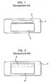
- FIG. 1 is a front view of a conventional front panel according to the ETR type
- FIG. 2 is a front view of a conventional front panel according to the flip down type.
- the ETR type front panel is configured to include an insertion hole 2 (or entrance) formed at an upper portion thereof, and through which a data storage medium, such as cassette tape, compact disk (CD), mini disk, etc., is inserted, and a display section 3 provided below the insertion hole 2.
- a liquid crystal display LCD is generally used as the display section 3.
- the flip down type front panel is configured to include a display section 6 formed throughout upper and lower portions of the front panel 4, and an insertion hole 5 provided in the front of the set.
- the display section 6 is selectively shielded by the front panel 4.
- the display section 6 of the flip down type front panel 4 is sized larger than the display section 3 of the ETR type front panel 1.
- the flip down type has an improved convenience of use because of the larger display area.
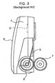
- FIG. 3 is a side view of a conventional flip down type car audio front panel driving apparatus.
- a display section is provided throughout the entire area of a front panel 4.
- An apparatus for opening and closing the front panel 4 will now be described.
- a driving gear 7 which is supplied with a driving force of a separate motor (not shown) and thereby rotates is provided at one side of the car audio main body, and a slave gear 8 in mesh with and moving in combination with the driving gear 7 is provided in one end of the front panel 4.
- a spring 9 for providing a restoring force is provided at the rotational center shaft of the slave gear 8 such that the front panel 4 is opened and is then restored to a closed status.
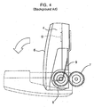
- FIG. 4 is a schematic view for illustrating an operation of the conventional flip down type front panel. As shown in FIG. 4 , the conventional flip down type front panel 4 rotates up and down around the rotational center shaft of a slave gear 8.
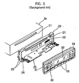
- FIG. 5 is a disassembled perspective view of a conventional flip down type car audio.
- the conventional flip down type car audio includes a main chassis 10 having an insertion hole 11 for information medium such as compact disc, mini disc, cassette tape and so on, a panel coupling section 20 as a fixing section formed in the front of the main chassis 10 to rotate a front panel 30, and an escutcheon section 25 coupled to the panel coupling section 20 to be rotatable along upward and downward directions.
- An entrance 22 in the panel coupling section 20 corresponds to the insertion hole 11.
- a rotational shaft 24 at both lower portions of the front side of the-panel coupling section 20 rotatably supports the escutcheon section 25.
- the rotational shaft 24 includes a pair of damping gears 23 engaged with each other such that the escutcheon section 25 is slowly and downwardly rotatable. Also, a hanging protrusion 21 at an upper edge portion of the panel coupling section 20 restrains the downward rotation of the front panel 30 from the standing status.
- the front panel 30 further includes a display section 32 for outputting and displaying information, a plurality of operating buttons 33 for selecting and operating the functions of the car audio, and an insertion groove 31 formed at both side portions of the front panel 30 into which both side edges of the escutcheon section 25 are inserted.
- a release button 34 for releasing the hanging status of the hanging protrusion 21 so that the front panel 30 is downwardly rotatable.
- the front panel 30 By rotating the front panel 30 upwardly, the upper edge of the front panel 30 is hung and maintained to the hanging protrusion 21 of the panel coupling section 20, so that the standing status of the front panel 30 is stably maintained.
- the release button 34 of the front panel 30 is pushed, and the hanging protrusion 21 is disconnected.
- the front panel 30 rotates downwardly around the rotational shaft 24 by the elastic force of a spring (not shown).
- the damping gear 23 restrains an abrupt rotation of the front panel 30 such that it rotates gradually. Accordingly, the entrance 22 of the panel coupling section 20 is opened and viewed from an outside.
- the escutcheon section 25 and the front panel 30 are further formed in the front of the entrance 22 for the information medium so as to shield the entrance 22.
- the front panel 30 rotates downwardly, there occurs a problem in watching the display section 32 formed in front of the front panel 30 and operating the operating buttons 33.
- the operation of the conventional flip down type front panel shown in FIGs. 2 to 5 is provided in additional detail in U.S. Patent No. 5,010,437 .
- the prior art has various disadvantages.
- the size of the display section 3 is made small in size.
- the conventional flip down type shown in FIGs. 2 to 5 there exist user's inconveniences because the operation is manually performed, and although the display section 6 is turned on, it cannot be viewed in the open status of the front panel 30.
- the front panel has an advantage in that the display section can be viewed in the open status of the front panel.
- a smooth movement of the front panel is hindered sometimes because the front panel is sensitive to external conditions such as temperature, humidity and so on owing to a complicated mechanical operation.
- the front panel has another disadvantage because a sufficient device reliability cannot be obtained due to the complicated mechanical operation when inserting or withdrawing compact disc, mini disc, cassette tape and so on.
- U.S. Patent No. 5,941,615 which corresponds to the preamble of claim 1, describes a movable structure for a display which is used in an audio apparatus.
- EP 0 995 972 A1 describes a car navigation system having a gyro-sensor.
- JP 11177248 describes a front panel operation mechanism having a guide member which is slidable back and forth for preventing instable operation of an electronic device of a car.
- An object of the invention is to solve at least the above problems and/or disadvantages and to provide at least the advantages described hereinafter.
- Another object of the present invention is to provide a front panel operating apparatus of a car display device that substantially obviates one or more problems due to limitations and disadvantages of the related art.
- Another object of the present invention is to provide a front panel operating apparatus of a car display device that enables a stable manipulation of the front panel for opening and closing the display part.
- a front panel operating apparatus of a car audio as recited in claim 1 that includes a main chassis configured to receive an audio device, wherein the audio device is configured to receive and eject an information medium through an entrance, a front panel coupled to the main chassis having a display part exposed in a front side, wherein the front panel selectively covers the entrance, a protruded section protruded from an upper portion of at least one of the main chassis and the front panel toward the other of the main chassis and the front panel, a guide configured to engage the protruded section, wherein the guide is coupled to the other of the main chassis and the front panel, wherein the guide extends a prescribed distance in substantially a first direction, a supporting panel pivotably coupled to a lower portion of the front panel, wherein the supporting panel is configured to reciprocably move in substantially a second direction that is perpendicular to the first direction, a supporting panel driving section configured to
- a device that includes a main chassis configured to receive an audio device, a front panel coupled to the main chassis, wherein the front panel is configured to selectively cover an entrance for providing a record medium to the audio device, wherein the front panel includes a front surface, wherein a viewable display is exposed in the front surface, and a driving member configured to drive the front panel to move forward and backward from the main chassis, wherein the driving member is configured to selectively change an inclination angle of the front panel with respect to the main chassis between at least three positions.
- a method of operating a front panel apparatus of a vehicular display device that includes providing a main chassis configured to receive an audio device, coupling a front panel to the main chassis for selectively covering an entrance for providing a record medium to the audio device, wherein the front panel includes a front surface having a viewable display exposed therein, pivotably driving a lower portion of the front panel to move forward and backward from the main chassis to selectively change an inclination angle of the front panel with respect to the main chassis to at least one viewing position between a closed position of the front panel and an open position of the front panel, and maintaining a coupling between an upper portion of the front panel and the main chassis when the front panel is moved.
- a front panel operating apparatus of a display device that includes a main chassis configured to receive the display device member, a gyro device coupled to the main chassis such that an installation angle to the main chassis is controllable, and an adjustment device configured to adjust the installation angle of the gyro device.
- FIG. 1 is a front view of a conventional electronic tuning (ETR) type front panel
- FIG. 2 is a front view of a conventional flip down type front panel
- FIG. 3 is a side view of a conventional flip down type car audio front panel driving apparatus
- FIG. 4 is a schematic view for illustrating an operation of a conventional flip down type front panel
- FIG. 5 is a disassembled perspective view of a conventional flip down type car audio
- FIG. 6 is a diagram showing a front sectional view of a front panel operating apparatus of a car audio according to a first example
- FIGs. 7 and 8 are diagrams showing detailed views of main portions of FIG. 6 ;
- FIG. 9 is a diagram showing a plan view of the front panel operating apparatus of the car audio of FIG. 6 ;
- FIG. 10 is a diagram showing a side view for illustrating an operation of the front panel operating apparatus of the car audio of FIG. 6 ;
- FIG. 11 is a diagram showing a front view of the front panel of FIG. 6 according the first example
- FIG. 12 is a block diagram showing the front panel operating apparatus of the car audio
- FIG. 13 is a diagram showing a side view of a supporting panel driving section according to a second example
- FIG. 14 is a diagram showing a plan view of a supporting panel driving section according to the second example.
- FIG. 15 is a diagram showing a front view of a pinion according to the second example.
- FIG. 16 is a diagram showing a side sectional view of a pinion according to the second example.
- FIG. 17 is a diagram showing a side view of a supporting panel driving section according to a third example.
- FIG. 18 is a diagram showing a plan view of a supporting panel driving section according to the third example.
- FIG. 19 is a diagram showing a front view of a pinion according to the third example.
- FIG. 20 is a diagram showing a side sectional view of a pinion according to the third example.
- FIG. 21 is a diagram showing a schematic view for illustrating an operation of a spacing maintaining section in the pinion according to the third example
- FIG. 22 is a diagram showing a sectional view of a clutch device according to a fourth example.
- FIG. 23 is a diagram showing a sectional view of a clutch device according to a fifth example.
- FIG. 24 is a diagram showing a sectional view and front view of a first gear according to the fifth example.
- FIG. 25 is a diagram showing a sectional view and front view of a second gear according to the fifth example.
- FIG. 26 is a diagram showing a schematic view for illustrating an operation of the clutch device according to the fifth example.
- FIG. 27 is a diagram showing a front view of a car audio to which a gyro device is attached according to a sixth example
- FIG. 28 is a diagram showing a plan sectional view of a gyro-equipped structure for navigation in a car audio according to a seventh embodiment of the present invention.
- FIG. 29 is a diagram showing a side view of main portions in the gyro-equipped structure for navigation according to an embodiment of the present invention.
- FIG. 30 is a diagram showing a front view of the gyro-equipped structure for navigation according to an embodiment of the present invention.
- FIG. 31 is a diagram showing a schematic view for illustrating the installation appearance of the gyro device according to an embodiment of the present invention.
- FIG. 32 is a diagram showing a plan sectional view of a front panel operating apparatus of a car audio according to a seventh example.
- FIG. 33 is a diagram showing a schematic view for illustrating an operation status of the front panel operating apparatus of the car audio according to the seventh example.
- Example 1 Preferred examples and embodiments for describing the present invention will now be provided. However, the invention is not intended to be restricted to the provided embodiments.
- Example 1
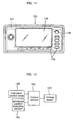
- a front panel operating apparatus of the car display device such as a car audio according to a first embodiment of the present invention can include a main chassis 100 preferably having a cylindrical shape of which one end is opened for accommodating a compact disc player 102 and a cassette player 103 or the like, and a front panel 125 provided at the front side of the main chassis 100 that can move in upward and downward directions to adjust its inclination angle.
- the inclination angle can be set to a user desired angle between an open and closed position or with fine increments or graduations between the open and closed positions.
- a supporting panel 120 can be positioned inside a lower side of the main chassis 100 to be withdrawn in forward and backward directions, and a protruded section 137 (see FIG. 9 ) can be formed along a plate surface direction at upper portions of preferably both sides of the front panel 125.
- An upper and lower guide 136 can be formed in the front of the main chassis 100 to accommodate and guide the movement of the protruded section 137 along generally upward and downward directions.
- a supporting panel driving section 130 (see FIG. 9 ) can drive the supporting panel 120 such that an inclination angle of the front panel 125 is controlled with respect to the main chassis 100.
- the supporting panel 120 is preferably withdrawn from or enters a withdrawal position detecting section 105 (see FIG.
- a control section 150 can control the supporting panel driving section 130 preferably based on a detection result of the withdrawal position detecting section 105 to control the inclination angle of the front panel 125 with respect to the main chassis 100.
- a compact disc player 102 and/or a cassette tape player 103 or the like can be accommodated preferably in a two layered structure.
- the exemplary compact disc player 102 can have an entrance 104 for withdrawing a compact disc from the upper side of the main chassis 100
- the exemplary cassette tape player 103 can have an entrance 101 for withdrawing a cassette tape from the lower side of the main chassis 100.
- a plurality of guide rollers 116 can be rotatable coupled to lower portions of both inner edges of the main chassis 100 preferably along the withdrawal and insertion (e.g., entrance) directions of the supporting panel 120.
- a front frame 145 (see FIG. 10 ) can be formed at an opened portion of the front side of the main chassis 100.
- the upper and lower guide 136 can be formed preferably at both inner edges of the front frame 145 to guide the upward and downward moving directions of the front panel 125.
- the front frame 145 preferably has an extended width compared with the width of the front panel 125 so as to accommodate the front panel 125.
- the front frame 145 can be included to couple the front panel 125 to the main chassis 100.
- the upper and lower guide 136 preferably accommodates the protruded section 137 outwardly protruded from upper portions of both side ends, and the rollers 138.
- the respective accommodated roller 138 are preferably in rolling-contact with inner side surfaces of the upper and lower guides 136, and are formed in a groove shape (e.g., rectangular cross-section) so as to move along the upward and downward directions.
- the lower ends of the upper and lower guides 136 are preferably formed to be curved toward the forward direction so that the movement of the protruded section 137 is smoothly guided.
- the supporting panel 120 can have a rectangular plate shape of which a center portion is partially cut off or removed. At both side edges of the supporting panel 120 along the width direction, preferably there are formed guide rails 118 that can have a U-shaped section to be in rolling-contact with the guide rollers 116. In the front end of the both side edges of the supporting panel 120, there can be a screw hole 141, which is preferably screw-coupled along with the lower side of the front panel 125, and a fixing screw 140, which preferably penetrates the screw hole 141 and is fixed thereto. It is desirable that the screw hole 141 is sufficiently loosely processed with respect to the fixing screw 140 to make possible the relative movement of the supporting panel 120 and the front panel 125. However, the present invention is not intended to be so limited as other pivotable connections, hinge-connections or controllable-connections between the support panel 120 and the front panel 125 can be used.
- the supporting panel driving section 130 can include a rack 131 formed extending along a prescribed length on an upper surface of one edge of the supporting panel 120 in the withdrawal direction (e.g., insertion or moving direction) of the supporting panel 120, a pinion 134 in mesh with the rack 131, and a pinion driving motor 133 for rotatably driving the pinion 134 in forward and backward directions.
- a rotational shaft 132 can couple the driving motor 133 with the pinion 134.
- the pinion 134 is preferably rotatably coupled integrally with the rotational shaft 132 of the pinion driving motor 133 and preferably arranged perpendicularly to the withdrawal direction of the supporting panel 120 inside the main chassis 100.
- the withdrawal position detecting section 105 can include a plurality of position detecting sensors 108 preferably spaced from each other in the withdrawal and entrance directions of the supporting panel 120, and a sensor switch 106 fixedly arranged within the main chassis 100 and that can output a detection signal based on contacting or correspondence with the respective position detection sensors 108.
- the sensor switch can include a contact pin 107, which is preferably protruded or retracted in upward and downward directions and enables the position detection of the position detecting sensor 108.
- the position detecting sensor 108 can use various kinds and shapes.
- a sensor rail 160 can also be formed on the upper surface of the supporting panel 120 in the moving direction of the supporting panel such that the contact pin 107 is not hung and the supporting panel 120 is slidingly movable.
- a horizontal guide section 110 can be formed at both sides spaced of the lower side of the supporting panel 120 to reduce or prevent the supporting panel 120 from being shaken in the horizontal direction.
- the horizontal guide section 110 can include an inverse "U"-shaped guide groove 121 having a lower surface that is formed protrudedly upwardly, a supporting shaft 122 upwardly protruded from the lower surface of the main chassis 100, and a guide protrusion 123 insertedly formed on the supporting shaft 122 so as to be slidingly in contact with the guide groove 121.
- the guide protrusion 123 can be insertedly formed in upward and downward directions with respect to the supporting shaft 122 with a predetermined measurements or margin such that it is movable in upward and downward directions and is also rotatable.
- a buffer member 124 is preferably further formed below the guide protrusion 123 to buffer and support the guide protrusion 123.
- the front panel 125 can include the display section 126 for displaying predetermined information, and an operating panel section 127.
- the operating panel section 127 can include an inclination control knob 128 and a plurality of operating buttons 129 preferably formed at a periphery of the display section 126 for selecting and operating the functions of an audio device such as the compact disc player 102 and/or the cassette tape player 103 or the like accommodated inside the main chassis 100.
- the inclination control knob 128 can preferably manually control the inclination angle of the front panel 125 with respect to the main chassis 100.
- the control section 150 can store a control program and can include at least a microprocessor.
- the control section 150 preferably can send a driving signal for controlling the inclination angle of the front panel 125 to the driving motor 133 based on detection results of the inclination control knob 128 and the withdrawal position detecting section 105.
- the rotatable inclination control knob 128, the withdrawal position detecting section 105 and the driving motor 133 are respectively and electrically coupled with the control section 150.
- the inclination control knob 128 shown in FIGS. 6-12 is the rotary type.
- the present invention is not intended to be so limited.
- the inclination control knob 128 may be constituted in the form of a plurality of push buttons that are installed corresponding to the number of the respective position detecting sensors 108 to designate the positions of the respective position detecting sensors 108, or in the form of a single push button to select the inclination angle according to a number of operated (e.g., pushed) times or selection of a plurality of prescribed locations from a closed position.
- the inclination control knob 128 can be manipulated to designate a user's desired (e.g., preferred or preset) inclination angle of the front panel 125.
- the control section 150 preferably controls the driving motor 133 to rotate in the withdrawal direction of the supporting panel 120.
- the driving motor 133 starts to rotate, the pinion 134 coupled with the driving motor 133 rotates, and the rack 131 in mesh with the pinion 134 and the supporting panel 120 can be moved forward (e.g., withdrawal).
- the vertical or horizontal position of the supporting panel 120 can be supported by a vertical guide section 115 including the guide roller 116 and the guide protrusion 123.
- the relative positions of the supporting panel 120 in the horizontal and vertical directions can be stably maintained while the supporting panel 120 is slidingly moved and withdrawn outside the main chassis 100.
- the supporting panel 120 preferably can be withdrawn without a horizontal shaking by interaction of the guide groove 121, the guide protrusion 123 and the buffer member 124. Also, the supporting panel 120 preferably can be withdrawn without a vertical shaking by interaction of the guide roller 116 and the guide rail 118.
- the supporting panel 120 When the supporting panel 120 is withdrawn from the interior of the main chassis 100, the lower side of the front panel 125 is moved forward by the supporting panel 120 (e.g., pivotably), and the upper side of the front panel 125 is moved downwardly (e.g., approximately vertically) along the upper and lower guide 136 of the front frame 145 to preferably maintain contact between the main chassis 100 and the front panel 125. Accordingly, the supporting panel 120 can have a predetermined inclination angle with respect to the main chassis 100. Further, an inclination angle, which allows access to the entrance of a compact disc or cassette tape, is possible.
- the position of the supporting panel 120 e.g., inclination angle or user viewing angle
- the position of the supporting panel 120 e.g., inclination angle or user viewing angle
- the control section 150 controls the driving motor 133 to stop its operation based on the position detection signal. Accordingly, the inclination angle between the front panel 125 and the main chassis 100 can be maintained at a value designated by the inclination control knob 128.
- the inclination control knob 128 can be manipulated to select a standing (e.g., prescribed) inclination angle of the front panel 125. Then, operations described above can be variously performed again.
- the first example exemplarily describes and shows a case that the protruded section is formed at the upper portions of the both sides of the front panel and the upper and lower guide for accommodating the protruded section and guiding the protruded section in upward and downward directions is formed at both sides of the front side of the front frame.
- the protruded section can be formed in the main chassis or front frame and a concaved upper and lower guide for accommodating the protruded section is formed at both edges of the front panel.
- the first example exemplarily describes and shows a case that the plurality of position detecting sensors are arranged at predicted positions along the withdrawal direction (e.g., forward away from/backward toward the main chassis) of the supporting panel and the sensor switch is fixedly arranged in the main chassis so as to interact with the position detecting sensors such that the inclination angle of the front panel is controllable in multiple stages.
- the present invention is not intended to be so limited.
- the driving motor can be a stepping motor or servo motor
- the inclination angle of the front panel can be finely controllable without sensors by adjusting the revolution of the motor.
- a second example of a vehicle display device will now be described with reference to FIGS. 13-16 .
- the second example is similar to the first example, but has at least a difference from the first example in the supporting panel driving section. Descriptions of the second example will concentrate on the supporting panel driving section.
- the torque of the driving motor 133 can be transferred to the rack 131 via the single pinion 134 can have a disadvantage in the reliable power transmission.
- the second example can constitute a supporting panel driving section capable of increasing or guaranteeing a reliability of such power transmission.
- a supporting panel driving section can include a driving motor 230 preferably coupled to a main chassis (not shown in the drawings), a worm 231 formed at one end of the driving motor 230 for being supplied with a torque, a worm gear 232 in mesh with the worm 231 and a rack 212 preferably formed on an upper side surface of a supporting panel 210, a pinion 245 in mesh with the rack 212, and a gear train 240 formed at a connection portion of the worm gear 232 and the pinion 245.
- the gear train 240 can include a plurality of gears for being supplied with the torque.
- the pinion 245 can include a small gear section 246 and a large gear section 247 in mesh with one end of the gear train 240, for being supplied with the torque from the gear train 240.
- the small gear section 246 can be in mesh with the rack 212 and can be formed integrally with the large gear section 247 for transferring torque to the rack 212.
- the gear train 240 can be fixed to the main chassis and/or a predetermined fixing section extended from the main chassis or the like. Also, the gear train 240 can be formed so as to reduce the revolution of the driving motor 230 and thus increase torque. For instance, the dimension of the gear for transferring power can be made smaller than the dimension of the gear for being supplied with power.
- connection hole 215 can be formed at the front side of the supporting panel so as to be connected with the front panel.
- the connection hole 215 preferably allows the front panel to be opened when the supporting panel 210 is pushed forward.
- the torque (e.g., driving force) of the driving motor 230 is preferably transferred to the pinion 245, particularly to the large gear section 247 of the pinion 245, via the worm 231, the worm gear 232 and the gear train 240.
- the rack 212 which is coupled to or in mesh with the small gear section 246 of the pinion 245, can then move forward and backward controlled by the pinion 245.
- the supporting panel 210 in which the rack 212 is preferably fixedly formed (or coupled to) moves into the inside and out to the outside of the main chassis, and the front panel can be opened (e.g., closed) as an upper portion of the front panel moves down (e.g., up).
- FIG. 15 is a front view of a an exemplary pinion according to the second example
- FIG. 16 is a side sectional view of an exemplary pinion according to the second example.
- the pinion 245 can have the large gear section 247 and the small gear section 246 in the form of an integral structure, e.g., a single gear.
- the supporting panel 210 can reliably and stably move forward and backward. Further, even when a low price and lower power motor is used as the driving motor, it has an advantage to sufficiently drive the supporting panel 210.
- a third example of a vehicle display device according to the present invention will now be described.
- the third example is similar to the second example, but has at least a difference from the second example in the shape, structure and operations of a pinion.
- the second example can include the pinion 245 with the large gear section 247 in mesh with a final gear of the gear train 240, and the small gear section 246 in mesh with the rack 212 on the supporting panel 210.
- the supporting panel 210 on which the rack 212 is installed can be spaced by a predetermined margin from the main chassis preferably to enhance the assembly convenience and provide smooth operation.
- a force is applied to the engagement between the pinion 245 and the rack 212 can depend on movement of the supporting panel 210 so that a central distance between the pinion 245 and the rack 212 can change.
- the central distance between the pinion 245 and the rack 212 can be greater than a previously designed value, and then, the teeth of the pinion 245 can collide with the teeth of the rack 212. In this case, the wearing of the teeth is generated and operational noise can increase or become serious.
- the distance between the pinion 245 and the rack 212 is too distant (e.g., above a threshold limit)
- power transmission between the pinion 245 and the rack 212 can become less efficient and even impossible.
- the third example discloses a central distance between gears that can be maintained at a constant value.
- the third example can include a driving motor 330, a worm 331, a worm gear 332, a gear train 340, a supporting panel 310, a connection hole 315 and a rack 350 operatively coupled to move the supporting panel 310 similar to corresponding features in the second example.
- a pinion 345 of the third example in mesh with one end of the rack 350 and the gear train 340 can include a spacer feature or method. As shown in FIG.
- the pinion 345 can include a large gear section 347 in mesh with one end of the gear train 340, a small gear section 346 in mesh with the rack 350, and a spacing maintaining section 348 can be formed between the large gear section 347 and the small gear section 346.
- the present invention is not intended to be so limited.
- the spacing maintaining section 348 can protruded from an approximate center of the pinion 345 toward the outer circumference thereof to have a diameter preferably greater than the diameter of the large gear section 347.
- the spacing maintaining section 348 preferably has a diameter that is sufficient to be in contact with the main chassis or a portion extended from the main chassis, and/or one side of the supporting panel 310.
- the torque (e.g., driving force) generated from the driving motor 330 is transferred via the worm 331, the worm gear 332, the gear train 340, and the pinion 345, and is preferably finally supplied to the rack 350 and the supporting panel 310.
- the central distance between the pinion 345 and the rack 350 can be preferably maintained at a constant value.
- the spacing maintaining section 348 of the pinion 345 can be in contact with the surface of the main chassis and/or the supporting panel 310, so that the central distance between the pinion 345 and the rack 350 is maintained at a constant value.
- the central distance between the pinion 345 and the rack 350 varies from than a designed central distance, and thus they are close to each other. Further, a noise generated by interference of the teeth of the pinion 345 and the teeth of the rack 350 is reduced or prevented and the pinion 345 can be moved reliably.
- the spacing maintaining section 348 is preferably made to be in contact with the supporting panel 310 so that the pinion 345 and the rack 350 operate stably.
- a front frame 355, an upper and lower guide 356, and a front panel 360 are shown in FIG. 21 .
- a fourth example of a vehicle display device will now be described with reference to FIG. 22 .
- the fourth example is similar to the second example or the third example, but has at least a difference of a clutch device preferably added as one element of a gear train (e.g., gear train 240, 340).
- a clutch device can be included to reduce or prevent the apparatus from damage such as being fractured when the moving distance of the supporting panel approaches a dead point, or a force over a constant limit (e.g., threshold) is applied toward the rack or the supporting panel, or to block the transfer of the torque with respect to an external force over a certain value.
- a constant limit e.g., threshold
- the clutch device according to the fourth example can be included as one element of a gear train.
- the clutch device can include a first gear 410 and a second gear 420, which are supported rotatably on a rotational shaft 405 whose both ends are preferably supported by a separate structure.
- Each of the first gear 410 and the second gear 420 preferably has a gear section 411, 421 formed on the outer circumference thereof.
- the gear section can be configured such that the first gear is supplied with a power from an outside through the gear section 411 and the second gear 420 transfers a power to an outside through the gear section 421.
- a frictional member 430 can be interposed between the facing surfaces of the first gear 410 and the second gear 420.
- the clutch device can include a contact spring 435 for providing a compressive force pushing the first gear 410 toward the second gear 420 such that the first gear 410 and the second gear 420 are closely in contact with each other with the frictional member 430 interposed therebetween.
- the contact spring 435 can have one end supported by the first gear 410 and the other end supported by a stopper 415 formed on the outer circumference of the rotational shaft 405.
- the position of the second gear 420 is preferably stably fixed by a stopper 425 provided at one end of the rotational shaft 405.
- power transmission between the first gear 410 and the second gear 420 is preferably smoothly performed by a frictional force between the frictional member 430 and the first gear 410, and a frictional force between the frictional member 430 and the second gear 420.
- the elastic force of the contact spring 435 preferably functions to increase the intensity of the frictional force.
- the first gear 410 can be coupled with a drive source or a power transmission device and supplied with a power
- the second gear 420 can be with a load to transfer a power toward the load.
- the present invention is not intended to be so limited. Then, power is transmitted from the first gear 410 to the second gear 420 by the elastic force of the contact spring 435 and the frictional force of the frictional member 430, so that the power of the drive source (e.g., driving motor) is transmitted to the load (e.g., supporting panel) through the clutch device.
- the drive source e.g., driving motor
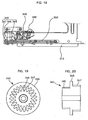
- a fifth example of a vehicle display device will now be described with reference to FIGS. 23-26 .
- the fifth example can be similar to the fourth example, but has at least a difference from the fourth example in a clutch device of the fifth example.
- the clutch device of the fourth example preferably uses the frictional force formed between the first gear 410 and the second gear 420. If the frictional force of the frictional member 430 is changed because of various factors such as variation in the temperature condition or the like, there occurs a problem in that the clutch device does not operate normally or predictably.
- the frictional coefficient of the frictional member 430 between the first gear 410 and the second gear 420 can be influenced by an external condition.
- the fifth example can provide a clutch device that enables an induction of an intermittence of power transmission and precisely or predictably operates only with the structure thereof (e.g., regardless of an external condition).
- the clutch device 500 can include a rotational shaft 505, a first gear 510, a second gear 520, a stopper 515, 525, a gear section 511, 521, and a contact spring 535 operably coupled similar to the fourth example.
- the fifth example has at least a difference in that an unevenness section 530, 550 can be substituted for the frictional member 430 of the fourth example.
- the first gear 510 can include a gear section 511 constituting an outer circumference of the first gear 510, and a first unevenness section 530 formed on one surface of the first gear 510 and in which a relatively protruded prominence section 531 and a relatively concaved depression section 532 are preferably alternatively formed.
- the relative sizes of the sections can be varied.
- a center penetration hole 512 can be formed at the center portion of the first gear 510 such that the rotational center shaft 505 is penetrated therethrough.
- the second gear 520 can include a gear section 521 constituting an outer circumference of the second gear 520 and for transmitting a power by being engaged with the gear section of another gear, a second unevenness section 550 formed on one surface of the second gear 520 and in which a relatively protruded prominence section 551 and a relatively concaved depression section 552 are preferably alternatively formed.
- a center penetration hole 522 can be formed at the center portion of the second gear 520 such that the rotational center shaft 505 is penetrated therethrough.
- the shape and size of the prominence section 551 and the depression section 552 of the second unevenness section 550 be approximately the same as the shape and size of the depression section 532 and the prominence section 531 of the first unevenness section 530.
- the present invention is not intended to be so limited.
- power transmission between the first gear 510 and the second gear 520 can be performed by the engagement of the first unevenness section 530 and the second unevenness section 550.
- the first gear 510 and the second gear 520 can preferably rotate along with each other.
- the position on which the first gear 510 and the second gear 520 are mounted can be out of line so that the first gear 510 and the second gear 520 run idle.
- the clutch can operate stably with respect to the strong resistant force of the load side.
- the coupling of the first unevenness section 530 and the second unevenness section 550 is not influenced by another surrounding conditions other than the elastic force of the contact spring 535. This is because the frictional force between the first unevenness section 530 and the second unevenness section 550 can be determined by the shape (e.g., the symmetric shape) matching between the prominence 535, 552 and the depression 531, 551 (e.g., slope).
- torque can be generated/transferred to the first gear 510 via the motor 560, the worm 561, the worm gear 562, and the driving gear 563. After passing through the clutch device provided in the fifth example, the torque is transferred from the second gear 520 to a slave gear 565.
- the primary or greatest factor for maintaining the coupling between the unevenness can be the elastic force of the contact spring, and the coupling is not influenced by external other factor such as temperature or the like. Accordingly, operational reliability of the apparatus can be enhanced.
- a sixth example of a vehicle display device will now be described with reference to FIG. 27 .
- the sixth example is similar to and can be combined with the first example to the fifth example, but has at least a difference in that a gyro device (e.g., gyro sensor) can provided to perform or improve a navigation function or role.
- a gyro device e.g., gyro sensor
- the gyro device can be a kind of orientation sensor, and can sense the moving direction of a motion body to more closely or precisely measure the position of the motion body in a navigation apparatus. Also, in case the navigation apparatus is attached to a car audio or the like such as in a main chassis, the use efficiency of the car audio and capability of the car audio can be further enhanced.
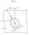
- FIG. 27 is a diagram that shows a front view of a car audio to which a gyro device is attached according to the sixth example.
- the car audio can include a main chassis 610, and a gyro device 620 attached to an inside or outside of the main chassis 610.
- the gyro device 620 is installed with a specific slope corresponding to an installation angle of the main chassis 610.
- Fig. 27 shows that the gyro device 620 is installed with a slope of 30 degrees from a vertical line (v) normal to the ground or a reference surface.
- the present invention is not intended to be so limited.
- the gyro device 620 is preferably installed parallel with the ground.
- the car audio is installed in a vehicle without a separate navigation apparatus on which a gyro device is mounted. Accordingly, a convenient use or more efficient use of the navigation apparatus becomes possible.
- This embodiment of the present invention is similar to the sixth example, but has at least a difference from the sixth example in an installation structure and process of the gyro device.
- the installation angle of the gyro device can be changed depending on the constitution of a dashboard in the vehicle on which the navigation apparatus is installed.
- normal operations of the gyro device can be realized only when the gyro device is preferably in parallel with the ground or in a prescribed orientation.
- the gyro device when installing a gyro device on the dashboard of a vehicle, it is preferred that the gyro device be in parallel with the ground.
- the navigation apparatuses e.g., car audio
- the navigation apparatuses e.g., car audio
- the compatibility of the gyro device is lowered, the productivity is lowered, and the maintenance on the gyro device is more work or effort.
- This embodiment can improve an installation accuracy, reduce cost, increase productivity and maintenance of the gyro device.
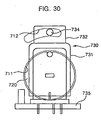
- a front panel operating apparatus of a car audio can include a main chassis 710, a gyro device 730 equipped inside or outside the main chassis 710, and a groove section 711 formed on one surface of the main chassis 710 and on which the gyro device 730 can be mounted.
- the groove section 711 is preferably made in a circular form.
- a communication hole 738 for communicating the outside of the main chassis 710 with the inside of the main chassis 710 can be formed preferably at the center of the groove section 711.
- a control slot 712 can be formed near (e.g., over) the groove section 711.
- the control slot 712 can penetrate the main chassis 710 and is preferably formed to have a predetermined curvature. However, the present invention is not intended to be so limited. An exemplary curvature of the control slot 712 will be again described later.
- the gyro device 730 can include a gyro housing 731 constituting the outer shell of the gyro device 730, and a plurality of hooks 736 formed on one surface of the gyro housing 731, (e.g., on a surface corresponding to one surface of the main chassis 710).
- the hooks 736 preferably have one surface closely contacting with the inner circumferential surface of the communication hole 738, and one end can be hung on the groove section 711 corresponding to an edge of the communication hole 738. Between the hooks a hanging section 737 can be formed.
- the hanging section 737 can be provided for coupling with a holder 720, which can be preferably installed inside the main chassis 710 corresponding to the groove section 711.
- a supporting die 732 can be protrudedly formed on the housing 731, and a bracket 733 can be installed on the supporting die 732.
- a coupling hole 734 can also be formed to penetrate the bracket 733 and the supporting die 732.
- the coupling hole 734 can be formed at a position corresponding to the control slot 712.
- the distance from the rotational center of the gyro device 730 to the coupling hole 734 is preferably equal to the distance from the center of the communication hole 738 to the control slot 712.
- the control slot 712 can be formed along a trace that the coupling hole 734 forms as the gyro device 730 rotates.
- the gyro device 730 can further include a substrate 735.
- a coupling screw 740 can preferably penetrate the control slot 712, the supporting die 732 of the gyro device 730 and the bracket 733 from the outside of the main chassis 710, and its position can then be fixed to preferably fix the gyro device 730.
- the coupling screw 740 can include a head section 741 having a diameter preferably greater than the width of the control slot 712, and a body section 742 formed extendingly from the head section 741.
- the body section 742 has a diameter that is smaller than the width of the control slot 712.
- the body section 742 preferably has a screw thread formed on the outer circumferential surface.
- the holder 720 can be coupled to an interior of the main chassis 710 where the gyro device 730 is placed.
- the holder 720 can be mounted on the groove section 711 and is coupled with the gyro device 730.
- the holder 720 can allow the gyro device 730 to be rotatably mounted on the main chassis 710, and can also function to shield the communication hole 738.
- the holder 720 can include a guide 721 formed correspondingly to the hook 736 of the gyro device 730, and a hanger section 722 formed correspondingly to the hanging section 737 of the gyro device 730.
- the guide 721 can be inserted between the hooks 736 facing with each other preferably closely in contact with the inner surface of the hooks 736 of the gyro device 730.
- the hanger section 722 can be hung with the hanging section 737 of the gyro device 730 inside, to couple the holder 720 with the gyro device 730.
- the present invention is not intended to be so limited.
- various coupling structures can be applied to rotatably affix the gyro device 730 to the main chassis 710.
- the seventh embodiment provides a two connection point installation apparatus and method for fixing or adjusting the installation angle of the gyro device.
- other adjustable connections can be used such as a plurality of holes for the control slot.
- the hook 736 of the gyro device 730 is preferably inserted into the communication hole 738 formed in the groove section 711 of the main chassis 710.
- the hook 736 is mounted on the communication hole 738, preferably the end of the hook 736 is hung on the inner surface of the groove section 711 corresponding to an edge of the communication hole 738. Accordingly, the gyro device 730 can preferably rotate around the communication hole 738.
- the coupling hole 734 can be placed at a location corresponding to the control slot 712 of the main chassis 710.
- the installation angle of the gyro device 730 is preferably controllable by rotating the gyro device 730 using the coupling hole 734 within the range of the control slot 712.
- the coupling screw 740 penetrates the control slot 712 and can then be coupled to the coupling hole 734. If the coupling screw 740 is coupled to the coupling hole 734, the head section 741 is closely in contact with one surface of the main chassis 710 corresponding to an edge of the control slot 712 so that the gyro device 730 can be fixedly equipped at a certain angle or desired angle to the main chassis 710.
- the holder 720 can then be mounted on the groove section 711 to shield the communication hole 738.
- the holder 720 is preferably formed in a size corresponding to the groove section 711 so as to shield the communication hole 738.
- the guide 721 of the holder 720 can be guided along the inner surface of the hook 736, inserted and closely in contact with the hook 736.
- the hanger section 722 can be hung on the hanging section 737 of the gyro device 730 such that the holder 720 is coupled with the gyro device 730.
- the coupling of the holder 720 can be performed prior to coupling the coupling screw 740.
- the installation angle of the car audio should be changed, for example, to be matched with a concrete specification of a vehicle and thus the installation angle of the gyro device 730 should be also changed.
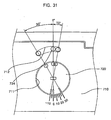
- the coupling screw 740 can be loosened such that the gyro device 730 is rotatable around the communication hole 738, and the position of the coupling hole 734 can be moved along the control slot 712 as shown in FIG. 31 .
- the coupling screw 740 can again be fastened and the installation angle of the gyro device is fixed.
- FIG. 31 is a schematic view for illustrating the installation appearance of the gyro device according to this embodiment of the present invention.
- the installation angle of the gyro device 730 can be changed within a range of 10 degree clockwise to 30 degree counterclockwise.
- the present invention is not intended to be so limited to such a range or such graduations.
- This embodiment can be formed and used in various motion bodies or navigation devices in addition to the exemplary car audio. If necessary, the installation angle of the gyro device 730 can be changed.
- the gyro-equipped structure of a car audio enables control the installation angle of the gyro device, which can compensate for the installation angle of the car audio or the like. Accordingly, by changing the installation angle of a single gyro device, the single gyro device can be compatibly used in car audios of various vehicles, so that productivity can be increased.
- the seventh example is similar to the first example, but has at least a difference from the first example in the constitution of the supporting panel driving section providing the driving force for the movement of the supporting panel.
- the seventh example can use a driving pulley and lead screw as the supporting panel driving section to smoothly control the velocity ratio for power transmission and increase a reliability in the power transmission.
- a horizontal guide section, vertical guide section, a position sensing section, a front frame, a front panel and a supporting panel in the seventh example can be similar to the first example but a portion moving the supporting panel forward and backward at least is different.
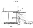
- a supporting panel driving section can include a driving motor 810 whose position is preferably fixed, for example, to a main chassis 800, a driving pulley 811 formed at one end of the rotational shaft of the driving motor 810 and a belt 812 of which one end can be wound on the driving pulley 811. The other end of the belt 812 can be hung and wound on a slave pulley 813.
- the supporting panel driving section can further include a lead screw 820 concentrically arranged with the rotational center of the slave pulley 813, and a moving sphere 825 preferably engaged with the thread of the lead screw 820 and fixedly formed on one surface of the supporting panel.
- the lead screw 820 can rotate along with the slave pulley 813.
- the lead screw 820 can convert the rotational movement of the lead screw 820 to a linear movement of the moving sphere 825 since the lead screw 820 penetrates and can be installed to the moving sphere 825.
- the moving sphere(s) 825 can move in combination with the lead screw 820 along the lead screw 820 thereby driving the supporting panel forward and backward.
- the driving motor 810 rotates, its rotational shaft rotates too.
- the rotational force of the driving motor 810 can be transmitted to the driving pulley 811, the belt 812 and the slave pulley 813, and accordingly, the lead screw 820 rotates.
- the moving sphere 825 or plurality of moving spheres can move along the lead screw 820 and the supporting panel moves outside the main chassis 800 so that the front panel preferably operates to adjust an inclination angle.
- FIG. 33 such operations are shown by a front frame 830, a front panel 835, and an upper and lower guide 840.
- the front panel operating apparatus of a car audio according to the seventh example transmits the driving force of the driving motor by using the pulley, belt and lead screw, so that the front panel can operate stably and reliably.
- Embodiments allow the manipulation of the front panel of a car audio to be performed more reliably, with graduated control, for example, to a plurality of intermediate inclined locations, and regardless of external conditions.
- the mechanical constitution can be less expensive, easier to manufacture and is automatically controllable, so that a user can locate the front panel to a desired position.
Landscapes
- Engineering & Computer Science (AREA)
- Mechanical Engineering (AREA)
- Radar, Positioning & Navigation (AREA)
- Remote Sensing (AREA)
- Multimedia (AREA)
- Physics & Mathematics (AREA)
- Automation & Control Theory (AREA)
- General Physics & Mathematics (AREA)
- Computer Networks & Wireless Communication (AREA)
- Signal Processing (AREA)
- Fittings On The Vehicle Exterior For Carrying Loads, And Devices For Holding Or Mounting Articles (AREA)
- Casings For Electric Apparatus (AREA)
- Toys (AREA)
Claims (3)
- Frontplattenbedienungsvorrichtung für ein Autoradio, mit:einem Hauptrahmen (710), der dazu geeignet ist, ein Audiogerät aufzunehmen;einer mit dem Hauptrahmen (710) verbundenen Frontplatte (125) mit einem in einer Vorderseite freiliegenden Displayteil;einem vom Hauptrahmen (710) oder von der Frontplatte (125) zum anderen dieser Elemente hin hervorstehenden Vorsprungabschnitt (137);einer Führung (136), die dafür konfiguriert ist, mit dem Vorsprungabschnitt in Eingriff zu kommen, wobei die Führung mit dem anderen Element von dem Hauptrahmen und der Frontplatte verbunden ist, und wobei die Führung sich im Wesentlichen in eine erste Richtung über eine vorgegebene Strecke erstreckt;einer mit einem unteren Abschnitt der Frontplatte (125) schwenkbar verbundenen Halteplatte (120), wobei die Halteplatte dafür konfiguriert ist, sich im Wesentlichen in eine bezüglich der ersten Richtung senkrecht erstreckende zweite Richtung hin- und hergehend zu bewegen;einem Halteplattenantriebsabschnitt (130), der dafür konfiguriert ist, die Halteplatte (120) in die zweite Richtung zu bewegen, um einen Neigungswinkel der Frontplatte steuerbar einzustellen; undeiner an einer Innenfläche oder einer Außenfläche des Hauptrahmens (710) befestigten Gyrovorrichtung (730) zum Bestimmen einer Bewegungsrichtung eines Fahrzeugs;dadurch gekennzeichnet, dass die Frontplattenbedienungsvorrichtung ferner aufweist:eine Einstelleinrichtung, die dafür konfiguriert ist, den Installationswinkel der Gyrovorrichtung (730) einzustellen, wobei die Einstelleinrichtung aufweist:eine im Hauptrahmen (710) ausgebildete Verbindungsöffnung (738), die als Drehmitte zum Steuern des Installationswinkels der Gyrovorrichtung (730) dient;einen Steuerschlitz (712), der konzentrisch zur Mitte der Verbindungsöffnung (738) angeordnet und derart ausgebildet ist, dass er einer Drehtrajektorie einer Seite der Gyrovorrichtung (730) entspricht;einen Haken (736), der auf einem eine Außenschale der Gyrovorrichtung (730) bildenden Gyrogehäuse (731) hervorstehend ausgebildet ist und mit einem Innenumfang der Verbindungsöffnung (738) in Eingriff steht; undeine Verbindungsschraube (740), die sich durch den Steuerschlitz (712) erstreckt und mit einer Seite des Gyrogehäuses (731) verbunden ist, mit einem Kopfabschnitt (741), der an einer ausgewählten Position des Steuerschlitzes (712) montiert ist, zum Fixieren des Installationswinkels der Gyrovorrichtung (730) und zum festen Verbinden der Gyrovorrichtung (730) mit dem Hauptrahmen (710).
- Vorrichtung nach Anspruch 1, ferner mit:einem Nutenabschnitt (711), der durch Vertiefen einer Außenfläche des Hauptrahmens (710) in der Umgebung der Verbindungsöffnung (738) ausgebildet ist; undeinem Halter (720), der auf dem Nutenabschnitt (711) montiert und mit der Gyrovorrichtung (730) drehbar verbunden ist, wobei der Halter (720) eine dem Haken (736) des Gyrogehäuses (731) entsprechende Hakenführung (721) aufweist.
- Vorrichtung nach Anspruch 2, wobei der Halter (720) und das Gyrogehäuse (731) jeweils einen Aufhängungsabschnitt (722) haben, der an einer entsprechenden Position für eine Verbindung zwischen dem Halter (720) und dem Gyrogehäuse (731) ausgebildet ist.
Priority Applications (1)
| Application Number | Priority Date | Filing Date | Title |
|---|---|---|---|
| EP08162928A EP1997684A3 (de) | 2002-02-26 | 2003-02-25 | Vorrichtung zum Betrieb einer Fronttafel |
Applications Claiming Priority (11)
| Application Number | Priority Date | Filing Date | Title |
|---|---|---|---|
| KR2002010307 | 2002-02-26 | ||
| KR10-2002-0010307A KR100446772B1 (ko) | 2002-02-26 | 2002-02-26 | 카오디오의 프론트패널 구동장치 |
| KR2002035465 | 2002-06-24 | ||
| KR10-2002-0035465A KR100461648B1 (ko) | 2002-06-24 | 2002-06-24 | 클러치장치 |
| KR2002053948 | 2002-09-06 | ||
| KR10-2002-0053948A KR100520950B1 (ko) | 2002-09-06 | 2002-09-06 | 카오디오의 프론트패널 개폐장치 |
| KR10-2002-0055859A KR100476420B1 (ko) | 2002-09-13 | 2002-09-13 | 네비게이션용 자이로 장착구조 |
| KR2002055859 | 2002-09-13 | ||
| KR2002069360 | 2002-11-08 | ||
| KR1020020069360A KR20040040971A (ko) | 2002-11-08 | 2002-11-08 | 기어 및 그 기어를 이용한 패널 구동장치 |
| EP03004209A EP1342620A3 (de) | 2002-02-26 | 2003-02-25 | Vorrichtung und Verfahren für die Bewegung einer Frontplatte einer Audioeinrichtung |
Related Parent Applications (1)
| Application Number | Title | Priority Date | Filing Date |
|---|---|---|---|
| EP03004209A Division EP1342620A3 (de) | 2002-02-26 | 2003-02-25 | Vorrichtung und Verfahren für die Bewegung einer Frontplatte einer Audioeinrichtung |
Related Child Applications (1)
| Application Number | Title | Priority Date | Filing Date |
|---|---|---|---|
| EP08162928A Division EP1997684A3 (de) | 2002-02-26 | 2003-02-25 | Vorrichtung zum Betrieb einer Fronttafel |
Publications (3)
| Publication Number | Publication Date |
|---|---|
| EP1577164A2 EP1577164A2 (de) | 2005-09-21 |
| EP1577164A3 EP1577164A3 (de) | 2006-02-01 |
| EP1577164B1 true EP1577164B1 (de) | 2008-11-12 |
Family
ID=27761618
Family Applications (3)
| Application Number | Title | Priority Date | Filing Date |
|---|---|---|---|
| EP05011461A Expired - Lifetime EP1577164B1 (de) | 2002-02-26 | 2003-02-25 | Vorrichtung und Verfahren für die Bewegung einer Frontplatte einer Audioeinrichtung |
| EP08162928A Withdrawn EP1997684A3 (de) | 2002-02-26 | 2003-02-25 | Vorrichtung zum Betrieb einer Fronttafel |
| EP03004209A Withdrawn EP1342620A3 (de) | 2002-02-26 | 2003-02-25 | Vorrichtung und Verfahren für die Bewegung einer Frontplatte einer Audioeinrichtung |
Family Applications After (2)
| Application Number | Title | Priority Date | Filing Date |
|---|---|---|---|
| EP08162928A Withdrawn EP1997684A3 (de) | 2002-02-26 | 2003-02-25 | Vorrichtung zum Betrieb einer Fronttafel |
| EP03004209A Withdrawn EP1342620A3 (de) | 2002-02-26 | 2003-02-25 | Vorrichtung und Verfahren für die Bewegung einer Frontplatte einer Audioeinrichtung |
Country Status (7)
| Country | Link |
|---|---|
| US (2) | US6883759B2 (de) |
| EP (3) | EP1577164B1 (de) |
| JP (2) | JP2003257166A (de) |
| CN (1) | CN1275799C (de) |
| AT (1) | ATE413988T1 (de) |
| DE (1) | DE60324705D1 (de) |
| ES (1) | ES2314517T3 (de) |
Families Citing this family (45)
| Publication number | Priority date | Publication date | Assignee | Title |
|---|---|---|---|---|
| JP4245451B2 (ja) * | 2003-10-03 | 2009-03-25 | 三菱電機株式会社 | 車載機器用のパネル駆動装置 |
| JP4211585B2 (ja) * | 2003-11-28 | 2009-01-21 | ソニー株式会社 | 再生装置 |
| TWI270293B (en) * | 2004-05-12 | 2007-01-01 | E Lead Electronic Co Ltd | Foldable multimedia display device |
| EP1766616A4 (de) * | 2004-06-14 | 2012-01-04 | Sava Cvek | Ausfahr- und einfahranordnungen |
| JP2006012262A (ja) * | 2004-06-24 | 2006-01-12 | Alpine Electronics Inc | 電子機器及びその媒体排出方法 |
| JP4099594B2 (ja) * | 2004-07-30 | 2008-06-11 | ソニー株式会社 | 記憶媒体収納装置 |
| US20060150869A1 (en) * | 2004-12-08 | 2006-07-13 | Sava Cvek | Computer components adjustable between storage and use configurations |
| WO2006063279A2 (en) * | 2004-12-08 | 2006-06-15 | Sava Cvek | Emergency and security condition retractable computer arrangements |
| US7597290B2 (en) * | 2005-03-30 | 2009-10-06 | Fujitsu Ten Limited | Tilting apparatus and electronic apparatus |
| US8112772B2 (en) | 2005-06-02 | 2012-02-07 | Fujitsu Ten Limited | Electronic apparatus |
| PL1956954T3 (pl) * | 2005-12-07 | 2018-12-31 | Essity Hygiene And Health Aktiebolag | Pakiet zapasu do stosowania w aparacie do wydawania materiału arkuszowego i aparat do wydawania materiału arkuszowego |
| JP4765696B2 (ja) * | 2006-03-16 | 2011-09-07 | ソニー株式会社 | 車載機器 |
| JP4597893B2 (ja) * | 2006-03-29 | 2010-12-15 | クラリオン株式会社 | 映像オーディオ装置の防塵構造 |
| US9237685B2 (en) | 2006-08-18 | 2016-01-12 | Delphi Technologies, Inc. | Lightweight audio system for automotive applications and method |
| US7733659B2 (en) | 2006-08-18 | 2010-06-08 | Delphi Technologies, Inc. | Lightweight audio system for automotive applications and method |
| DE102006056391B3 (de) * | 2006-11-29 | 2008-04-30 | Siemens Ag | Navigationsrechner |
| JP4842785B2 (ja) * | 2006-12-04 | 2011-12-21 | 富士通テン株式会社 | 車載用電子システム及び車載電子装置 |
| US20080162044A1 (en) * | 2006-12-28 | 2008-07-03 | Fujitsu Ten Limited | In-vehicle electronic apparatus and in-vehicle electronic system |
| JP2008137559A (ja) * | 2006-12-04 | 2008-06-19 | Fujitsu Ten Ltd | 車載用電子システム、車載電子装置及び携帯電子装置の電源制御方法 |
| US20080159557A1 (en) * | 2006-12-27 | 2008-07-03 | Fujitsu Ten Limited | Electronic apparatus, electronic system and method of controlling sound output |
| US7684200B2 (en) * | 2006-12-28 | 2010-03-23 | Fujitsu Ten Limited | Electronic apparatus and electronic system |
| US7765046B2 (en) * | 2006-12-28 | 2010-07-27 | Fujitsu Ten Limited | In-vehicle electronic apparatus and in-vehicle electronic system |
| US20080161950A1 (en) * | 2006-12-28 | 2008-07-03 | Fujitsu Ten Limited | Electronic system, electronic apparatus and method of operating audio unit |
| US8706396B2 (en) * | 2006-12-28 | 2014-04-22 | Fujitsu Ten Limited | Electronic apparatus and electronic system |
| US7860643B2 (en) * | 2006-12-28 | 2010-12-28 | Fujitsu Ten Limited | In-vehicle detachably electronic apparatus and in-vehicle electronic system |
| US7904236B2 (en) * | 2006-12-28 | 2011-03-08 | Fujitsu Ten Limited | Electronic apparatus and electronic system |
| US7774104B2 (en) * | 2006-12-27 | 2010-08-10 | Fujitsu Ten Limited | Electronic apparatus and electronic system |
| US20080157999A1 (en) * | 2006-12-28 | 2008-07-03 | Fujitsu Ten Limited | Electronic apparatus, electronic system and method of controlling audio output |
| JP2008141076A (ja) * | 2006-12-04 | 2008-06-19 | Fujitsu Ten Ltd | 携帯電子機器の着脱装置 |
| US7869196B2 (en) * | 2006-12-28 | 2011-01-11 | Fujitsu Ten Limited | Electronic apparatus |
| CN101394718B (zh) * | 2007-09-21 | 2010-08-04 | 乐金电子(昆山)电脑有限公司 | 车辆用机器面板的跌落防止装置 |
| WO2009090698A1 (ja) * | 2008-01-16 | 2009-07-23 | Mitsubishi Electric Corporation | モニタパネル装置 |
| US20100103598A1 (en) * | 2008-10-24 | 2010-04-29 | Fujitsu Ten Limited | Electronic apparatus and method for the same |
| WO2010099415A1 (en) | 2009-02-27 | 2010-09-02 | Delphi Technologies, Inc. | Lightweight audio system for automotive appalications and method |
| KR101374813B1 (ko) * | 2012-03-28 | 2014-03-19 | 주식회사 글로벌스탠다드테크놀로지 | 판재 자세 조절 장치 |
| CN104316072A (zh) * | 2014-10-21 | 2015-01-28 | 重庆金宏汽车电子有限公司 | 车辆导航器 |
| JP6592205B2 (ja) * | 2016-11-18 | 2019-10-16 | 本田技研工業株式会社 | 車載電子機器取付構造 |
| CN106714478A (zh) * | 2016-11-21 | 2017-05-24 | 北京四方继保自动化股份有限公司 | 一种防护机箱 |
| CN108116327B (zh) * | 2016-11-30 | 2020-02-21 | 比亚迪股份有限公司 | 车载显示屏装置及车辆 |
| CN108236380B (zh) * | 2016-12-23 | 2024-01-16 | 宁波方太厨具有限公司 | 一种水箱、控制面板联动机构及应用有该机构的家用电器 |
| CN107750041A (zh) * | 2017-11-22 | 2018-03-02 | 科成精密模塑科技无锡有限公司 | 多功能车载音响精密模塑面板 |
| DE102019205344B4 (de) * | 2019-04-12 | 2024-05-16 | Volkswagen Aktiengesellschaft | Aufnahmesystem zur Aufnahme wenigstens einer geführten Einrichtung und ein Elektromodul, sowie ein Kraftfahrzeug |
| DE102019215197B4 (de) * | 2019-10-02 | 2022-09-29 | Volkswagen Aktiengesellschaft | Positionierungssystem zur Positionierung einer Anzeigeeinrichtung in einem Kraftfahrzeug sowie ein Kraftfahrzeug |
| CN113752829B (zh) * | 2020-06-05 | 2023-10-24 | 观致汽车有限公司 | 车载智能终端及具有其的车辆 |
| CN114040600B (zh) * | 2021-03-09 | 2023-06-30 | 杭州金砖信息技术有限公司 | 一种小型机房结构 |
Family Cites Families (24)
| Publication number | Priority date | Publication date | Assignee | Title |
|---|---|---|---|---|
| JPS5814366A (ja) * | 1981-07-20 | 1983-01-27 | Toshiba Corp | デジタルデイスクプレ−ヤのロ−デイング装置 |
| US4701902A (en) * | 1984-04-27 | 1987-10-20 | Pioneer Electronic Corporation | Automatic loading disc player |
| JP2622586B2 (ja) * | 1988-07-01 | 1997-06-18 | クラリオン株式会社 | 記憶媒体を装脱する車載用電子機器 |
| JPH081721B2 (ja) | 1989-06-07 | 1996-01-10 | パイオニア株式会社 | 記録媒体演奏装置 |
| EP0551078B1 (de) * | 1992-01-08 | 1996-10-09 | Pioneer Electronic Corporation | System zum Bewegen eines in einem Kraftfahrzeug montierten Fernsehgerätes |
| US5847685A (en) * | 1992-08-19 | 1998-12-08 | Alpine Electronics, Inc. | Vehicle-mounted display mechanism |
| JPH0714374A (ja) * | 1993-06-25 | 1995-01-17 | Clarion Co Ltd | オーディオ装置 |
| EP0734006B1 (de) | 1995-03-20 | 2002-03-27 | Aisin Aw Co., Ltd. | Anzeigegerät für Fahrzeug |
| JP3657038B2 (ja) * | 1995-05-23 | 2005-06-08 | クラリオン株式会社 | 車載用情報機器 |
| JPH09180332A (ja) * | 1995-12-28 | 1997-07-11 | Sony Corp | 電子機器 |
| KR980004919A (ko) * | 1996-06-21 | 1998-03-30 | 배순훈 | 카 오디오용 프론트 패널 로딩장치 |
| US5941615A (en) | 1996-10-23 | 1999-08-24 | Harness System Technologies Research, Ltd. | Movable structure for a display |
| JP3426474B2 (ja) | 1997-07-02 | 2003-07-14 | 富士通テン株式会社 | 車載用ディスプレイ装置 |
| US6301982B1 (en) | 1997-07-10 | 2001-10-16 | Mitsubishi Denki Kabushiki Kaisha | Variable mechanism for mounting angle housed gyro-sensor and method of mounting variable mechanism for mounting angle |
| JP4012295B2 (ja) | 1997-12-16 | 2007-11-21 | チューナー株式会社 | 電子機器におけるフロントパネルの作動機構 |
| JPH11297060A (ja) | 1998-04-14 | 1999-10-29 | Sony Corp | 音響再生装置 |
| KR20000033785A (ko) | 1998-11-25 | 2000-06-15 | 전주범 | 프론트 패널 틸팅 구조를 갖는 카오디오 |
| JP2001151030A (ja) * | 1999-11-30 | 2001-06-05 | Toyota Motor Corp | 開閉扉付き車載機器 |
| DE19962823A1 (de) | 1999-12-23 | 2001-06-28 | Mannesmann Vdo Ag | Für ein Kraftfahrzeug bestimmter Navigationsrechner |
| JP2001296129A (ja) * | 2000-04-18 | 2001-10-26 | Toyota Motor Corp | 角速度検出装置 |
| JP2001349738A (ja) * | 2000-06-08 | 2001-12-21 | Alpine Electronics Inc | ナビゲーション装置 |
| KR100352191B1 (ko) | 2000-12-06 | 2002-09-12 | 주식회사 현대오토넷 | 카 오디오 프론트 패널 슬라이딩 장치 |
| JP2002219971A (ja) * | 2001-01-26 | 2002-08-06 | Auto Network Gijutsu Kenkyusho:Kk | パネル駆動装置 |
| JP2002347529A (ja) * | 2001-05-24 | 2002-12-04 | Pioneer Electronic Corp | 電子機器 |
-
2003
- 2003-02-25 ES ES05011461T patent/ES2314517T3/es not_active Expired - Lifetime
- 2003-02-25 EP EP05011461A patent/EP1577164B1/de not_active Expired - Lifetime
- 2003-02-25 EP EP08162928A patent/EP1997684A3/de not_active Withdrawn
- 2003-02-25 DE DE60324705T patent/DE60324705D1/de not_active Expired - Lifetime
- 2003-02-25 AT AT05011461T patent/ATE413988T1/de not_active IP Right Cessation
- 2003-02-25 EP EP03004209A patent/EP1342620A3/de not_active Withdrawn
- 2003-02-25 US US10/372,122 patent/US6883759B2/en not_active Expired - Lifetime
- 2003-02-26 JP JP2003049330A patent/JP2003257166A/ja not_active Withdrawn
- 2003-02-26 CN CNB031075630A patent/CN1275799C/zh not_active Expired - Fee Related
-
2005
- 2005-02-25 US US11/065,004 patent/US7419123B2/en not_active Expired - Fee Related
-
2009
- 2009-04-23 JP JP2009105360A patent/JP2009163877A/ja active Pending
Also Published As
| Publication number | Publication date |
|---|---|
| EP1342620A3 (de) | 2003-12-17 |
| US7419123B2 (en) | 2008-09-02 |
| US20050139731A1 (en) | 2005-06-30 |
| EP1997684A3 (de) | 2009-04-08 |
| ES2314517T3 (es) | 2009-03-16 |
| CN1443670A (zh) | 2003-09-24 |
| EP1997684A2 (de) | 2008-12-03 |
| ATE413988T1 (de) | 2008-11-15 |
| US6883759B2 (en) | 2005-04-26 |
| EP1577164A2 (de) | 2005-09-21 |
| JP2003257166A (ja) | 2003-09-12 |
| EP1577164A3 (de) | 2006-02-01 |
| EP1342620A2 (de) | 2003-09-10 |
| US20030160135A1 (en) | 2003-08-28 |
| CN1275799C (zh) | 2006-09-20 |
| DE60324705D1 (de) | 2008-12-24 |
| JP2009163877A (ja) | 2009-07-23 |
Similar Documents
| Publication | Publication Date | Title |
|---|---|---|
| EP1577164B1 (de) | Vorrichtung und Verfahren für die Bewegung einer Frontplatte einer Audioeinrichtung | |
| US7184266B1 (en) | Automatic monitor sliding system | |
| EP1542435B1 (de) | Tragbares, verschiebbares Funkkommunikationsendgerät | |
| EP3070239A1 (de) | Öffnungsjustierkörper, öffnungsjustiervorrichtung und türkontrollmechanismus für fahrzeugtüren | |
| US4388712A (en) | Combined electronic apparatus indicator and cassette tape transducer apparatus, particularly combined radio-recorder for automotive use | |
| US20060055675A1 (en) | Systems and methods to move a keyboard | |
| JP2715451B2 (ja) | 液晶表示装置及び乗用車 | |
| JP3039719B2 (ja) | 車載用テレビ | |
| JPH03189620A (ja) | 車載用液晶ディスプレイ装置 | |
| KR200326357Y1 (ko) | 자동차용 에이브이 시스템의 모니터 인출구조 | |
| CN1808618B (zh) | 面板操作装置和方法 | |
| WO2000034079A1 (en) | Dual mode car stereo system capable of playing two different types of recording mediums | |
| KR100477246B1 (ko) | 차량용 모니터의 인출구조 | |
| JP4662395B2 (ja) | 車載用電子機器 | |
| JP3004103B2 (ja) | 車載用ディスプレイ装置 | |
| US5038238A (en) | Apparatus for opening and shutting a door accessing adjusting controls to a tape recorder | |
| JPH0640023Y2 (ja) | 車載用ディスプレイ装置 | |
| JP3257901B2 (ja) | 車載用表示装置 | |
| EP1193107A1 (de) | Anzeigegerät | |
| KR200342502Y1 (ko) | 차량용 모니터 자동 수납 장치 | |
| JPH05170031A (ja) | 車載用テレビ | |
| KR19990053102A (ko) | 자동차용 오디오/비디오 시스템 구동장치 | |
| KR100402218B1 (ko) | 루프 장착형 카 텔레비젼 | |
| KR20000033789A (ko) | 프론트 패널 틸팅 구조를 갖는 카오디오 | |
| KR100798621B1 (ko) | 패널 회전장치 |
Legal Events
| Date | Code | Title | Description |
|---|---|---|---|
| PUAI | Public reference made under article 153(3) epc to a published international application that has entered the european phase |
Free format text: ORIGINAL CODE: 0009012 |
|
| AC | Divisional application: reference to earlier application |
Ref document number: 1342620 Country of ref document: EP Kind code of ref document: P |
|
| AK | Designated contracting states |
Kind code of ref document: A2 Designated state(s): AT BE BG CH CY CZ DE DK EE ES FI FR GB GR HU IE IT LI LU MC NL PT SE SI SK TR |
|
| PUAL | Search report despatched |
Free format text: ORIGINAL CODE: 0009013 |
|
| AK | Designated contracting states |
Kind code of ref document: A3 Designated state(s): AT BE BG CH CY CZ DE DK EE ES FI FR GB GR HU IE IT LI LU MC NL PT SE SI SK TR |
|
| 17P | Request for examination filed |
Effective date: 20060801 |
|
| AKX | Designation fees paid |
Designated state(s): AT BE BG CH CY CZ DE DK EE ES FI FR GB GR HU IE IT LI LU MC NL PT SE SI SK TR |
|
| 17Q | First examination report despatched |
Effective date: 20061107 |
|
| 17Q | First examination report despatched |
Effective date: 20061107 |
|
| GRAP | Despatch of communication of intention to grant a patent |
Free format text: ORIGINAL CODE: EPIDOSNIGR1 |
|
| GRAS | Grant fee paid |
Free format text: ORIGINAL CODE: EPIDOSNIGR3 |
|
| GRAA | (expected) grant |
Free format text: ORIGINAL CODE: 0009210 |
|
| AC | Divisional application: reference to earlier application |
Ref document number: 1342620 Country of ref document: EP Kind code of ref document: P |
|
| AK | Designated contracting states |
Kind code of ref document: B1 Designated state(s): AT BE BG CH CY CZ DE DK EE ES FI FR GB GR HU IE IT LI LU MC NL PT SE SI SK TR |
|
| REG | Reference to a national code |
Ref country code: GB Ref legal event code: FG4D |
|
| REG | Reference to a national code |
Ref country code: CH Ref legal event code: EP |
|
| REG | Reference to a national code |
Ref country code: IE Ref legal event code: FG4D |
|
| REF | Corresponds to: |
Ref document number: 60324705 Country of ref document: DE Date of ref document: 20081224 Kind code of ref document: P |
|
| REG | Reference to a national code |
Ref country code: ES Ref legal event code: FG2A Ref document number: 2314517 Country of ref document: ES Kind code of ref document: T3 |
|
| PG25 | Lapsed in a contracting state [announced via postgrant information from national office to epo] |
Ref country code: AT Free format text: LAPSE BECAUSE OF FAILURE TO SUBMIT A TRANSLATION OF THE DESCRIPTION OR TO PAY THE FEE WITHIN THE PRESCRIBED TIME-LIMIT Effective date: 20081112 |
|
| PG25 | Lapsed in a contracting state [announced via postgrant information from national office to epo] |
Ref country code: SI Free format text: LAPSE BECAUSE OF FAILURE TO SUBMIT A TRANSLATION OF THE DESCRIPTION OR TO PAY THE FEE WITHIN THE PRESCRIBED TIME-LIMIT Effective date: 20081112 |
|
| PG25 | Lapsed in a contracting state [announced via postgrant information from national office to epo] |
Ref country code: EE Free format text: LAPSE BECAUSE OF FAILURE TO SUBMIT A TRANSLATION OF THE DESCRIPTION OR TO PAY THE FEE WITHIN THE PRESCRIBED TIME-LIMIT Effective date: 20081112 Ref country code: DK Free format text: LAPSE BECAUSE OF FAILURE TO SUBMIT A TRANSLATION OF THE DESCRIPTION OR TO PAY THE FEE WITHIN THE PRESCRIBED TIME-LIMIT Effective date: 20081112 Ref country code: BG Free format text: LAPSE BECAUSE OF FAILURE TO SUBMIT A TRANSLATION OF THE DESCRIPTION OR TO PAY THE FEE WITHIN THE PRESCRIBED TIME-LIMIT Effective date: 20090212 Ref country code: BE Free format text: LAPSE BECAUSE OF FAILURE TO SUBMIT A TRANSLATION OF THE DESCRIPTION OR TO PAY THE FEE WITHIN THE PRESCRIBED TIME-LIMIT Effective date: 20081112 |
|
| PG25 | Lapsed in a contracting state [announced via postgrant information from national office to epo] |
Ref country code: SE Free format text: LAPSE BECAUSE OF FAILURE TO SUBMIT A TRANSLATION OF THE DESCRIPTION OR TO PAY THE FEE WITHIN THE PRESCRIBED TIME-LIMIT Effective date: 20090212 Ref country code: PT Free format text: LAPSE BECAUSE OF FAILURE TO SUBMIT A TRANSLATION OF THE DESCRIPTION OR TO PAY THE FEE WITHIN THE PRESCRIBED TIME-LIMIT Effective date: 20090413 Ref country code: CZ Free format text: LAPSE BECAUSE OF FAILURE TO SUBMIT A TRANSLATION OF THE DESCRIPTION OR TO PAY THE FEE WITHIN THE PRESCRIBED TIME-LIMIT Effective date: 20081112 |
|
| PLBE | No opposition filed within time limit |
Free format text: ORIGINAL CODE: 0009261 |
|
| STAA | Information on the status of an ep patent application or granted ep patent |
Free format text: STATUS: NO OPPOSITION FILED WITHIN TIME LIMIT |
|
| PG25 | Lapsed in a contracting state [announced via postgrant information from national office to epo] |
Ref country code: MC Free format text: LAPSE BECAUSE OF NON-PAYMENT OF DUE FEES Effective date: 20090228 Ref country code: SK Free format text: LAPSE BECAUSE OF FAILURE TO SUBMIT A TRANSLATION OF THE DESCRIPTION OR TO PAY THE FEE WITHIN THE PRESCRIBED TIME-LIMIT Effective date: 20081112 |
|
| REG | Reference to a national code |
Ref country code: CH Ref legal event code: PL |
|
| 26N | No opposition filed |
Effective date: 20090813 |
|
| PG25 | Lapsed in a contracting state [announced via postgrant information from national office to epo] |
Ref country code: LI Free format text: LAPSE BECAUSE OF NON-PAYMENT OF DUE FEES Effective date: 20090228 Ref country code: CH Free format text: LAPSE BECAUSE OF NON-PAYMENT OF DUE FEES Effective date: 20090228 |
|
| REG | Reference to a national code |
Ref country code: IE Ref legal event code: MM4A |
|
| PG25 | Lapsed in a contracting state [announced via postgrant information from national office to epo] |
Ref country code: IE Free format text: LAPSE BECAUSE OF NON-PAYMENT OF DUE FEES Effective date: 20090225 |
|
| PGFP | Annual fee paid to national office [announced via postgrant information from national office to epo] |
Ref country code: ES Payment date: 20100209 Year of fee payment: 8 |
|
| PGFP | Annual fee paid to national office [announced via postgrant information from national office to epo] |
Ref country code: IT Payment date: 20100224 Year of fee payment: 8 |
|
| PG25 | Lapsed in a contracting state [announced via postgrant information from national office to epo] |
Ref country code: GR Free format text: LAPSE BECAUSE OF FAILURE TO SUBMIT A TRANSLATION OF THE DESCRIPTION OR TO PAY THE FEE WITHIN THE PRESCRIBED TIME-LIMIT Effective date: 20090213 |
|
| PG25 | Lapsed in a contracting state [announced via postgrant information from national office to epo] |
Ref country code: FI Free format text: LAPSE BECAUSE OF FAILURE TO SUBMIT A TRANSLATION OF THE DESCRIPTION OR TO PAY THE FEE WITHIN THE PRESCRIBED TIME-LIMIT Effective date: 20081112 |
|
| PG25 | Lapsed in a contracting state [announced via postgrant information from national office to epo] |
Ref country code: LU Free format text: LAPSE BECAUSE OF NON-PAYMENT OF DUE FEES Effective date: 20090225 |
|
| PGFP | Annual fee paid to national office [announced via postgrant information from national office to epo] |
Ref country code: FR Payment date: 20110218 Year of fee payment: 9 Ref country code: DE Payment date: 20110223 Year of fee payment: 9 |
|
| PG25 | Lapsed in a contracting state [announced via postgrant information from national office to epo] |
Ref country code: HU Free format text: LAPSE BECAUSE OF FAILURE TO SUBMIT A TRANSLATION OF THE DESCRIPTION OR TO PAY THE FEE WITHIN THE PRESCRIBED TIME-LIMIT Effective date: 20090513 |
|
| PGFP | Annual fee paid to national office [announced via postgrant information from national office to epo] |
Ref country code: GB Payment date: 20110223 Year of fee payment: 9 |
|
| PG25 | Lapsed in a contracting state [announced via postgrant information from national office to epo] |
Ref country code: TR Free format text: LAPSE BECAUSE OF FAILURE TO SUBMIT A TRANSLATION OF THE DESCRIPTION OR TO PAY THE FEE WITHIN THE PRESCRIBED TIME-LIMIT Effective date: 20081112 |
|
| REG | Reference to a national code |
Ref country code: NL Ref legal event code: V1 Effective date: 20110901 |
|
| PG25 | Lapsed in a contracting state [announced via postgrant information from national office to epo] |
Ref country code: CY Free format text: LAPSE BECAUSE OF FAILURE TO SUBMIT A TRANSLATION OF THE DESCRIPTION OR TO PAY THE FEE WITHIN THE PRESCRIBED TIME-LIMIT Effective date: 20081112 |
|
| PG25 | Lapsed in a contracting state [announced via postgrant information from national office to epo] |
Ref country code: IT Free format text: LAPSE BECAUSE OF NON-PAYMENT OF DUE FEES Effective date: 20110225 Ref country code: NL Free format text: LAPSE BECAUSE OF NON-PAYMENT OF DUE FEES Effective date: 20110901 |
|
| REG | Reference to a national code |
Ref country code: ES Ref legal event code: FD2A Effective date: 20120510 |
|
| PG25 | Lapsed in a contracting state [announced via postgrant information from national office to epo] |
Ref country code: ES Free format text: LAPSE BECAUSE OF NON-PAYMENT OF DUE FEES Effective date: 20110226 |
|
| GBPC | Gb: european patent ceased through non-payment of renewal fee |
Effective date: 20120225 |
|
| REG | Reference to a national code |
Ref country code: FR Ref legal event code: ST Effective date: 20121031 |
|
| REG | Reference to a national code |
Ref country code: DE Ref legal event code: R119 Ref document number: 60324705 Country of ref document: DE Effective date: 20120901 |
|
| PG25 | Lapsed in a contracting state [announced via postgrant information from national office to epo] |
Ref country code: GB Free format text: LAPSE BECAUSE OF NON-PAYMENT OF DUE FEES Effective date: 20120225 Ref country code: FR Free format text: LAPSE BECAUSE OF NON-PAYMENT OF DUE FEES Effective date: 20120229 |
|
| PG25 | Lapsed in a contracting state [announced via postgrant information from national office to epo] |
Ref country code: DE Free format text: LAPSE BECAUSE OF NON-PAYMENT OF DUE FEES Effective date: 20120901 |
|
| PGFP | Annual fee paid to national office [announced via postgrant information from national office to epo] |
Ref country code: NL Payment date: 20100228 Year of fee payment: 8 |