EP1554176B1 - Formverfahren, insbesondere blas-und/oder vakuumformverfahren, zum herstellen eines mit einem abzugebenden medium gefüllten abgabebehälters - Google Patents
Formverfahren, insbesondere blas-und/oder vakuumformverfahren, zum herstellen eines mit einem abzugebenden medium gefüllten abgabebehälters Download PDFInfo
- Publication number
- EP1554176B1 EP1554176B1 EP03807746A EP03807746A EP1554176B1 EP 1554176 B1 EP1554176 B1 EP 1554176B1 EP 03807746 A EP03807746 A EP 03807746A EP 03807746 A EP03807746 A EP 03807746A EP 1554176 B1 EP1554176 B1 EP 1554176B1
- Authority
- EP
- European Patent Office
- Prior art keywords
- jowls
- container
- mould
- header
- plates
- Prior art date
- Legal status (The legal status is an assumption and is not a legal conclusion. Google has not performed a legal analysis and makes no representation as to the accuracy of the status listed.)
- Expired - Lifetime
Links
Images


Classifications
-
- B—PERFORMING OPERATIONS; TRANSPORTING
- B65—CONVEYING; PACKING; STORING; HANDLING THIN OR FILAMENTARY MATERIAL
- B65B—MACHINES, APPARATUS OR DEVICES FOR, OR METHODS OF, PACKAGING ARTICLES OR MATERIALS; UNPACKING
- B65B3/00—Packaging plastic material, semiliquids, liquids or mixed solids and liquids, in individual containers or receptacles, e.g. bags, sacks, boxes, cartons, cans, or jars
- B65B3/02—Machines characterised by the incorporation of means for making the containers or receptacles
- B65B3/022—Making containers by moulding of a thermoplastic material
-
- A—HUMAN NECESSITIES
- A61—MEDICAL OR VETERINARY SCIENCE; HYGIENE
- A61M—DEVICES FOR INTRODUCING MEDIA INTO, OR ONTO, THE BODY; DEVICES FOR TRANSDUCING BODY MEDIA OR FOR TAKING MEDIA FROM THE BODY; DEVICES FOR PRODUCING OR ENDING SLEEP OR STUPOR
- A61M5/00—Devices for bringing media into the body in a subcutaneous, intra-vascular or intramuscular way; Accessories therefor, e.g. filling or cleaning devices, arm-rests
- A61M5/178—Syringes
- A61M5/28—Syringe ampoules or carpules, i.e. ampoules or carpules provided with a needle
- A61M5/281—Syringe ampoules or carpules, i.e. ampoules or carpules provided with a needle using emptying means to expel or eject media, e.g. pistons, deformation of the ampoule, or telescoping of the ampoule
- A61M5/282—Syringe ampoules or carpules, i.e. ampoules or carpules provided with a needle using emptying means to expel or eject media, e.g. pistons, deformation of the ampoule, or telescoping of the ampoule by compression of deformable ampoule or carpule wall
-
- B—PERFORMING OPERATIONS; TRANSPORTING
- B29—WORKING OF PLASTICS; WORKING OF SUBSTANCES IN A PLASTIC STATE IN GENERAL
- B29C—SHAPING OR JOINING OF PLASTICS; SHAPING OF MATERIAL IN A PLASTIC STATE, NOT OTHERWISE PROVIDED FOR; AFTER-TREATMENT OF THE SHAPED PRODUCTS, e.g. REPAIRING
- B29C49/00—Blow-moulding, i.e. blowing a preform or parison to a desired shape within a mould; Apparatus therefor
- B29C49/02—Combined blow-moulding and manufacture of the preform or the parison
- B29C49/04—Extrusion blow-moulding
-
- A—HUMAN NECESSITIES
- A61—MEDICAL OR VETERINARY SCIENCE; HYGIENE
- A61M—DEVICES FOR INTRODUCING MEDIA INTO, OR ONTO, THE BODY; DEVICES FOR TRANSDUCING BODY MEDIA OR FOR TAKING MEDIA FROM THE BODY; DEVICES FOR PRODUCING OR ENDING SLEEP OR STUPOR
- A61M5/00—Devices for bringing media into the body in a subcutaneous, intra-vascular or intramuscular way; Accessories therefor, e.g. filling or cleaning devices, arm-rests
- A61M5/178—Syringes
- A61M5/31—Details
- A61M2005/3117—Means preventing contamination of the medicament compartment of a syringe
- A61M2005/3118—Means preventing contamination of the medicament compartment of a syringe via the distal end of a syringe, i.e. syringe end for mounting a needle cannula
- A61M2005/312—Means preventing contamination of the medicament compartment of a syringe via the distal end of a syringe, i.e. syringe end for mounting a needle cannula comprising sealing means, e.g. severable caps, to be removed prior to injection by, e.g. tearing or twisting
-
- A—HUMAN NECESSITIES
- A61—MEDICAL OR VETERINARY SCIENCE; HYGIENE
- A61M—DEVICES FOR INTRODUCING MEDIA INTO, OR ONTO, THE BODY; DEVICES FOR TRANSDUCING BODY MEDIA OR FOR TAKING MEDIA FROM THE BODY; DEVICES FOR PRODUCING OR ENDING SLEEP OR STUPOR
- A61M2207/00—Methods of manufacture, assembly or production
-
- A—HUMAN NECESSITIES
- A61—MEDICAL OR VETERINARY SCIENCE; HYGIENE
- A61M—DEVICES FOR INTRODUCING MEDIA INTO, OR ONTO, THE BODY; DEVICES FOR TRANSDUCING BODY MEDIA OR FOR TAKING MEDIA FROM THE BODY; DEVICES FOR PRODUCING OR ENDING SLEEP OR STUPOR
- A61M5/00—Devices for bringing media into the body in a subcutaneous, intra-vascular or intramuscular way; Accessories therefor, e.g. filling or cleaning devices, arm-rests
- A61M5/178—Syringes
- A61M5/28—Syringe ampoules or carpules, i.e. ampoules or carpules provided with a needle
- A61M5/285—Syringe ampoules or carpules, i.e. ampoules or carpules provided with a needle with sealing means to be broken or opened
- A61M5/286—Syringe ampoules or carpules, i.e. ampoules or carpules provided with a needle with sealing means to be broken or opened upon internal pressure increase, e.g. pierced or burst
-
- A—HUMAN NECESSITIES
- A61—MEDICAL OR VETERINARY SCIENCE; HYGIENE
- A61M—DEVICES FOR INTRODUCING MEDIA INTO, OR ONTO, THE BODY; DEVICES FOR TRANSDUCING BODY MEDIA OR FOR TAKING MEDIA FROM THE BODY; DEVICES FOR PRODUCING OR ENDING SLEEP OR STUPOR
- A61M5/00—Devices for bringing media into the body in a subcutaneous, intra-vascular or intramuscular way; Accessories therefor, e.g. filling or cleaning devices, arm-rests
- A61M5/178—Syringes
- A61M5/31—Details
- A61M5/32—Needles; Details of needles pertaining to their connection with syringe or hub; Accessories for bringing the needle into, or holding the needle on, the body; Devices for protection of needles
- A61M5/3205—Apparatus for removing or disposing of used needles or syringes, e.g. containers; Means for protection against accidental injuries from used needles
- A61M5/321—Means for protection against accidental injuries by used needles
- A61M5/3243—Means for protection against accidental injuries by used needles being axially-extensible, e.g. protective sleeves coaxially slidable on the syringe barrel
- A61M5/3275—Means for protection against accidental injuries by used needles being axially-extensible, e.g. protective sleeves coaxially slidable on the syringe barrel being connected to the needle hub or syringe by radially deflectable members, e.g. longitudinal slats, cords or bands
-
- B—PERFORMING OPERATIONS; TRANSPORTING
- B29—WORKING OF PLASTICS; WORKING OF SUBSTANCES IN A PLASTIC STATE IN GENERAL
- B29L—INDEXING SCHEME ASSOCIATED WITH SUBCLASS B29C, RELATING TO PARTICULAR ARTICLES
- B29L2031/00—Other particular articles
- B29L2031/753—Medical equipment; Accessories therefor
- B29L2031/7544—Injection needles, syringes
Definitions
- the invention relates to a molding process, in particular blow molding and / or vacuum molding process, for producing a dispensing container filled with a medium to be dispensed.
- the invention is directed to the production of such dispensing containers, the main but not exclusive use of which is to introduce a desired volume of the medium, in particular a liquid medium in a receptacle.
- the medium to be introduced is preferably an additive which, for example, is introduced as an active ingredient admixture into a fluid in the receptacle.
- the receptacle can be an infusion container to whose contents the medium is to be added as an additional active ingredient.
- a syringe As a dispensing container for this purpose usually a syringe is used, with the cannula a perforable closure or plug of the receptacle, such as the infusion container, is pierced, after which the medium is injected into the receptacle by expressing the syringe.
- the preparatory step of filling the syringe is required by transferring the desired amount of the medium from a reservoir into the syringe or filling the syringe from a conventional vial containing the metered dose of the medium in question.
- the integrated cannula and its protruding end, ie the needle tip, covering the safety device which covers the medium are combined to form an overall unit in the dispensing container produced by the method according to the invention.
- the desired dose of the medium in question can be provided in the dispensing container before the dispensing operation . Since the needle tip is covered by the securing device, the container with secured cannula can be easily handled in its ready for the dispensing process state. Intermediate steps of transferring medium and preparing a syringe are not required for the dispensing operation. The desired simplification, time savings and increased security against contamination are thus achieved.
- containers produced by the method according to the invention not only the risk of contamination of the medium is greatly reduced, but also reduces the risk that the user, such as a nurse injured, because the cannula is protected again after use by the securing device.
- the securing means of the closure unit may be designed so that after removal of the protective cover of the cannula protection body when piercing the closure by conditioning at the same from its advanced protective position at the end of the cannula in the position of use can be pushed back and after pulling out of the cannula from the closure back into the protective position can be advanced.
- the handling during the dispensing process is particularly simplified.
- the steps of widening and filling the container in the mold are carried out jointly by means of a combined blowing filling mandrel which extends through the introduction opening. This allows a particularly efficient production of the filled containers with short cycle times.
- the protective hood as an integrated part of the container and as part of the protective device is preferably formed when closing the head jaws of the mold in the region of the transition between the closure unit and protective cover on the wall of a predetermined breaking point, which forms a removal of the protective cover facilitating separation point.
- At least one protruding handle piece is formed, which forms a twist-off knob for convenient manual separation of the protective hood.
- an embodiment of a filled dispensing container produced by the method according to the invention is designated as a whole by 1.
- it is an ampoule-like plastic container whose wall 2 is provided with folds and bellows-shaped, so that the dispensing container 1 can be compressed from the configuration shown in FIGS. 6 to 9, see FIGS Neck is inserted into the dispensing container 1 as an insert part closure unit 3.
- the body 4 of the closure unit 3 is in the central region of FIG a cannula 11, the inner end 12 of which projects slightly inwardly over the body 4 of the closure unit 3.
- the body 4 of the closure unit 3 also has a first component 17 of a cannula securing device extending along the projecting part of the cannula.
- the second component of this securing device is a protective cover 5 surrounding the protruding part of the cannula 11, which is formed during the manufacture of the container 1 as an integral part thereof.
- the invention is explained below using the example of a blow molding process.
- the molding of the container with protective cover 5 could also be carried out by a vacuum molding process or a combined blow molding / vacuum molding process.
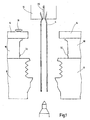
- FIGS. 1 to 5 The sequence of the molding process is illustrated in FIGS. 1 to 5, in which the essential parts of a molding device are shown in greatly simplified schematic form.
- the device comprises three pairs of movable mold jaws, namely main mold jaws 8 for forming the container to be dispensed receiving a main body, head jaws 10 for forming the closure unit 3 enclosing the upper container part, in the present example, the guard 5 of the securing device, and holding jaws 14 for stabilizing a
- This is extruded from a nozzle 18, which in a conventional manner has a terminal 20 for the supply of supporting air in the fully open in Fig.
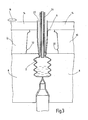
- Fig. 3 shows that through the insertion opening 22 through which is formed by the severing of the tube 6, a movable, combined blowing filling mandrel 24 is retracted, through which the expansion of the tube 6 is effected by means of blown air, so that the container wall. 2 conforming to the walls of the main mold jaws 8 in a bellows-like configuration, and then, after the inside of the container has been shaped, the medium to be dispensed is filled in by means of the combined blow-filling mandrel 24, see FIG. 3.
- the next step is the insertion of the closure unit 3 by means of a retractable through the insertion 22, movable suction pad 28, see Fig. 4.
- the body 4 of the shutter unit 3 has a conical surface, which on a seat 27 abuts, which forms the inner wall of the tube 6 in the area in which the mold walls of the main mold jaws 8 adjacent to the head jaws 10.
- Fig. 5 shows that further.
- Course of the suction pads 28 is moved away after completion of loading process up and the mold is now closed by moving together the head jaws 10, whereby the extending in the region of the head jaws 10 section of the tube 6 is formed to the protective cover 5.
- the head jaws 10 have a shaping projection 32 which upon closing of the head jaws 10 on the hose 6 forms an annular notch, which forms a predetermined breaking point 7, at which the protective cover 5 is to be separated easily from the rest of the container.
- a rotary knob 9 is formed as a handle, which allows a comfortable manual twisting off of the protective hood 5.
- the head jaws 10 have at diametrically opposite locations recesses to form two opposing rotary knob 9. Of these depressions, only in FIG. 4 is a recess 34 indicated by a dashed line.
- the cannula 11 extends from the outer end of the body 4 of the closure unit 3 in a length which corresponds approximately to the length of a syringe cannula.
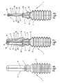
- FIGS. 6 and 7 show operating states in which the protruding outer end 15 of the cannula 11 is covered by both components of the securing device, that is to say both by the protective cover 5 and by the component denoted by 17 as a whole.
- This component 17 is integrally formed on the body 4 of the closure unit 3 and has an annular body 19 which is displaceable on the cannula 11 and in the protective position, see Figs. 7, 8 and 12, located at the outer end 15 of the cannula 11 to cover this cannula end, ie the needle tip.
- the annular body 19 is integrally connected via integrally molded support members 21 rod-like shape with the body 4 of the closure unit 3, wherein the joints with ring body 19 and body 4 of the closure unit 3 in the manner of bending joints are yielding. In addition, located on about half the length of the support members 21 bending joints 23, which divide the support members 21.
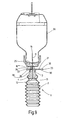
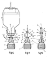
- FIGs. 10 and 9 show the container in the state where the cannula 11 has pierced with its front end 15 a perforable closure 25 of an infusion container 26.
- the annular body 19 is pushed back out of the protective position aligned with the end 15 of the cannula along the cannula 11 into the position of use.
- the pressure of the medium therein has been increased, so that the membrane 13 is pressed against the facing end 12 of the cannula 11 and pierced by this.
- the compression of the dispensing container 1 thereby leads to a squeezing of the medium therein into the infusion container 26, so that its content is added to the contents of the dispensing container 1 corresponding dose of an additive or active ingredient.
- the cannula 11 in the body 4 of the closure unit 3 could also be guided for a limited by stops (not shown) displacement movement that the cannula 11 is pushed back so far when piercing the shutter 25 that its end 12 the Membrane 13 perforated.
- Fig. 11 shows the operating state after the expressed dispensing container 1 is again withdrawn from the closure 25 of the infusion container 26. Due to the inherent elasticity of the carrier elements 21, the annular body has 19, which has previously been pushed back against the elasticity or holding force of the carrier elements 21 from the protective position during insertion of the cannula in the closure 25 by itself, partially by the elasticity force again partially against the end 15 of the cannula 11 pushed back.
- Fig. 12 shows the operating state of the container after the use thereof, wherein the protruding outer end 15 of the cannula 11, although the protective cover 5 is no longer attached, is secured again by the component 17 of the securing device.
- a removable on the body 4 of the shutter unit 3 locking ring 29 is removed from the body 4 of the shutter unit and advanced along the cannula 11, wherein it slides over the support members 21 and these from the position shown in Fig. 11 to the cannula 11, wherein the annular body 19 is advanced to the end 15 of the cannula 11.
- the support elements 21 have molded notches 30 into which the securing ring 29 engages, see FIG. 12.
- the dispensing container can not only be used to advantage for adding desired volumes of liquid media in infusion containers, but equally for the delivery of liquid, semi-solid or gaseous and / or particulate-laden media, as far as their delivery via cannulas is possible or necessary applied can be.
Landscapes
- Health & Medical Sciences (AREA)
- Engineering & Computer Science (AREA)
- Mechanical Engineering (AREA)
- Animal Behavior & Ethology (AREA)
- Public Health (AREA)
- Anesthesiology (AREA)
- Biomedical Technology (AREA)
- Heart & Thoracic Surgery (AREA)
- Hematology (AREA)
- Life Sciences & Earth Sciences (AREA)
- Veterinary Medicine (AREA)
- General Health & Medical Sciences (AREA)
- Vascular Medicine (AREA)
- Manufacturing & Machinery (AREA)
- Environmental & Geological Engineering (AREA)
- Medical Preparation Storing Or Oral Administration Devices (AREA)
- Blow-Moulding Or Thermoforming Of Plastics Or The Like (AREA)
- Moulds For Moulding Plastics Or The Like (AREA)
- Basic Packing Technique (AREA)
- Infusion, Injection, And Reservoir Apparatuses (AREA)
- Tubes (AREA)
Description
- Die Erfindung bezieht sich auf ein Formverfahren, insbesondere Blas- und/oder Vakuumformverfahren, zum Herstellen eines mit einem abzugebenden Medium gefüllten Abgabebehälters. Insbesondere richtet sich die Erfindung auf die Herstellung solcher Abgabebehälter, deren hauptsächlicher, jedoch nicht ausschließlicher Verwendungszweck darin besteht, ein gewünschtes Volumen des Mediums, insbesondere eines flüssigen Mediums, in einen Aufnahmebehälter einzubringen. Vorzugsweise handelt es sich bei dem einzubringenden Medium um einen Zusatzstoff, der beispielsweise als Wirkstoffbeimengung in ein im Aufnahmebehälter befindliches Fluid eingebracht wird. Bei dem Aufnahmebehälter kann es sich um einen Infusionsbehälter handeln, zu dessen Inhalt das Medium als zusätzlicher Wirkstoff beizumengen ist.
- Als Abgabebehälter wird hierzu üblicherweise eine Spritze benutzt, mit deren Kanüle ein perforierbarer Verschluß oder Stopfen des Aufnahmebehälters, beispielsweise des Infusionsbehälters, durchstochen wird, wonach durch Ausdrücken der Spritze das Medium in den Aufnahmebehälter injiziert wird. Bei diesem Vorgehen ist der vorbereitende Arbeitsschritt des Befüllens der Spritze erforderlich, indem die gewünschte Menge des Mediums aus einem Vorratsbehälter in die Spritze umgefüllt oder die Spritze aus einer konventionellen Phiole, die die abgemessene Dosis des betreffenden Mediums enthält, befüllt wird. Diese Arbeitsschritte des Umfüllens sind zum einen zeitraubend, weil Kanüle und Spritze ausgepackt, die Kanüle auf die Spritze montiert, die Phiole geöffnet oder angestochen werden und die Spritze aufgezogen werden müssen. Zum anderen besteht bei diesen Maßnahmen ein erhebliches Risiko der Kontamination des Mediums.
- Verfahren, die die simultane Ausbildung und Befüllung von Behältern durch Blasformen oder Vakuumformen ermöglichen, sind bereits bekannt. So zeigen beispielsweise die
DE 197 07 292 A1 und dieUS 5687550 ein derartiges Blasformverfahren. Die Erfindung stellt sich die Aufgabe, auf Grundlage eines derartigen Blasformverfahrens oder eines entsprechenden Vakuumformverfahrens ein Herstellungsverfahren für Abgabebehälter aufzuzeigen, das nicht nur eine besonders einfache und rationelle Herstellung der Behälter ermöglicht, sondern insbesondere auch für die Herstellung solcher Abgabebehälter vorgesehen ist, die eine besonders einfache, schnelle und sichere Abgabe des Mediums aus dem Abgabebehälter in einen Aufnahmebehälter ermöglichen. - Diese Aufgabe ist erfindungsgemäß durch ein Formverfahren gelöst, das die Merkmale des Anspruches 1 aufweist.
- Dadurch, dass erfindungsgemäß sowohl die Ausbildung des Behälters und dessen Befüllen mit dem betreffenden Medium als auch das Verschließen des gefüllten Behälters, einschließlich des Einlegens einer für den Abgabevorgang speziell ausgebildeten Verschlußeinheit mit einer aus mehreren Bestandteilen bestehenden Sicherungseinrichtung, innerhalb einer Formeinrichtung erfolgt, also an ein und demselben Herstellungsort, aus dem erst der vollständig gefertigte Abgabebehälter wegtransportiert zu werden braucht, ergibt sich eine besonders einfache Herstellung, bei der die zu fordernde Sterilität ohne Schwierigkeiten zu gewährleisten ist.
- Dadurch, dass bei dem mit dem erfindungsgemäßen Verfahren hergestellten, das Medium enthaltenden Abgabebehälter die integrierte Kanüle sowie eine deren vorstehendes Ende, also die Nadelspitze, abdeckende Sicherungseinrichtung zu einer Gesamteinheit zusammengefaßt sind, kann die gewünschte Dosis des betreffenden Mediums vor dem Abgabevorgang im Abgabebehälter bereitgestellt werden. Da die Nadelspitze durch die Sicherungseinrichtung abgedeckt ist, kann der Behälter mit gesicherter Kanüle ohne weiteres in seinem für den Abgabevorgang bereiten Zustand gehandhabt werden. Zwischenschritte des Umfüllens von Medium und des Bereitmachens einer Spritze sind für den Abgabevorgang nicht erforderlich. Die erstrebte Vereinfachung, Zeitersparnis und erhöhte Sicherheit gegen Kontamination sind somit erreicht. Bei nach dem erfindungsgemäßen Verfahren hergestellten Behältern ist nicht nur die Gefahr der Kontamination des Mediums stark reduziert, sondern auch die Gefahr verringert, dass sich der Benutzer, etwa eine Krankenschwester, verletzt, weil die Kanüle nach Gebrauch wieder durch die Sicherungseinrichtung geschützt ist.
- Wenn das äußere Ende der Kanüle dazu vorgesehen ist, einen perforierbaren Verschluß eines Aufnahmebehälters zu durchstoßen, der das abzugebende Medium aufnehmen soll, kann die Sicherungseinrichtung der Verschlußeinheit so gestaltet sein, dass nach dem Abnehmen der Schutzhaube der Kanülen-Schutzkörper beim Durchstoßen des Verschlusses durch Anlage an demselben aus seiner vorgeschobenen Schutzstellung am Ende der Kanüle in die Gebrauchsstellung zurückschiebbar und nach Herausziehen der Kanüle aus dem Verschluß wieder in die Schutzstellung vorschiebbar ist. Dadurch ist die Handhabung beim Abgabevorgang besonders vereinfacht.
- Bei einem besonders vorteilhaften Ausführungsbeispiel des Formverfahrens werden die Schritte des Aufweitens und des Füllens des in der Form befindlichen Behälters gemeinsam mittels eines die Einführöffnung durchgreifenden, kombinierten Blas-Fülldornes ausgeführt. Dadurch wird eine besonders rationelle Herstellung der gefüllten Behälter mit kurzen Taktzeiten ermöglicht.
- Im Zuge des Formens der Schutzhaube als integrierten Teil des Behälters und als Bestandteil der Schutzeinrichtung wird vorzugsweise beim Schließen der Kopfbacken der Form im Bereich des Überganges zwischen Verschlußeinheit und Schutzhaube an deren Wand eine Sollbruchstelle ausgeformt, die eine das Abnehmen der Schutzhaube erleichternde Trennstelle bildet.
- Vorzugsweise wird beim Schließen der Kopfbacke an der Schutzhaube zumindest ein vorspringendes Griffstück ausgeformt, das einen Abdrehknebel für bequemes manuelles Abtrennen der Schutzhaube bildet.
- Nachstehend ist die Erfindung anhand der Zeichnung im einzelnen erläutert. Es zeigen:
- Fig. 1 bis 3 stark schematisch vereinfacht gezeichnete Darstellungen wesentlicher Teile einer Formeinrichtung zum Durchführen des erfindungsgemäßen Verfahrens, wobei in diesen Fig. mehrere aufeinander folgende Schritte des Verfahrensablaufs verdeutlicht sind;
- Fig. 4 einen vergrößert gezeichneten Ausschnitt zur Verdeutlichung des Verfahrensschrittes des Einlegens einer dem Behälter zugehörigen Verschlußeinheit;
- Fig. 5 eine im Maßstab den Fig. 1 bis 3 entsprechende Darstellung der Formeinrichtung, wobei der Schritt des Formens einer die Verschlußeinheit umgebenden Schutzhaube verdeutlicht ist;
- Fig. 6 eine Seitenansicht eines Ausführungsbeispiels eines mit dem erfindungsgemäßen Formverfahren hergestellten Abgabebehälters in dem Betriebszustand vor dem Gebrauch, d. h. mit aufgesetzter Schutzhaube;
- Fig. 7 einen Längsschnitt des Abgabebehälters von Fig. 6;
- Fig. 8 einen der Fig. 7 entsprechenden Längsschnitt, jedoch mit abgenommener Schutzhaube;
- Fig. 9 einen Längsschnitt des Abgabebehälters in einem Betriebszustand, bei dem eine Abgabekanüle des Abgabebehälters in einen perforierbaren Verschlußstopfen eines Infusionsbehälters eingestochen ist;
- Fig. 10 eine der Fig. 9 ähnliche Darstellung, wobei jedoch der Abgabebehälter zur Abgabe enthaltenen Mediums ausgedrückt ist;
- Fig. 11 einen Längsschnitt des Abgabebehälters in ausgedrücktem und aus dem Verschlußstopfen abgezogenem Zustand und
- Fig. 12 einen Längsschnitt des Abgabebehälters im ausgedrückten, der Schutzstellung eines der Bestandteile der Sicherungseinrichtung entsprechenden Betriebszustand.
- In den Figuren ist ein Ausführungsbeispiel eines mit dem erfindungsgemäßen Verfahren hergestellten, gefüllten Abgabebehälters als Ganzes mit 1 bezeichnet. Bei dem gezeigten Ausführungsbeispiel handelt es sich um einen ampullenartigen Kunststoffbehälter, dessen Wand 2 mit Falten versehen und balgartig gestaltet ist, so dass der Abgabebehälter 1 aus der in Fig. 6 bis 9 gezeigten Konfiguration zusammengedrückt werden kann, siehe Fig. 10 bis 12. Im Halsbereich ist in den Abgabebehälter 1 als Einlegeteil eine Verschlußeinheit 3 eingesetzt. Wie am deutlichsten aus Fig. 4, 7 und 8 zu ersehen ist, ist der Körper 4 der Verschlußeinheit 3 im Zentralbereich von einer Kanüle 11 durchzogen, deren inneres Ende 12 über den Körper 4 der Verschlußeinheit 3 nach innen leicht vorsteht. Zwischen dem inneren Ende 12 der Kanüle 11 und dem Innenraum des Abgabebehälters 1 befindet sich eine Membran 13, die Teil des Einlegeteils der Verschlußeinheit 3 ist. Am Körper 4 der Verschlußeinheit 3 ist außerdem ein sich entlang des vorstehenden Teiles der Kanüle erstreckender erster Bestandteil 17 einer Kanülen-Sicherungseinrichtung gelagert. Zweiter Bestandteil dieser Sicherungseinrichtung ist eine den vorstehenden Teil der Kanüle 11 umhüllende Schutzhaube 5, die bei der Herstellung des Behälters 1 als integraler Bestandteil desselben gebildet wird. Nachstehend ist die Erfindung am Beispiel eines Blasformverfahrens erläutert. Die Formung des Behälters mit Schutzhaube 5 könnte auch durch ein Vakuumformverfahren oder ein kombiniertes Blas-/Vakuumformverfahren erfolgen.
- Der Ablauf des Formverfahrens ist in Fig. 1 bis 5 verdeutlicht, in denen die wesentlichen Teile einer Formeinrichtung stark schematisch vereinfacht dargestellt sind. Die Einrichtung weist drei Paare beweglicher Formbacken auf, nämlich Hauptformbacken 8 zur Formung des ein abzugebendes Medium aufnehmenden Behälter-Hauptteiles, Kopfbacken 10 zur Bildung des die Verschlußeinheit 3 umschließenden oberen Behälterteiles, beim vorliegenden Beispiel der Schutzhaube 5 der Sicherungseinrichtung, sowie Haltebacken 14 zur Stabilisierung eines extrudierten Kunststoffschlauches 6. Dieser wird aus einer Düse 18, die in an sich bekannter Weise einen Anschluß 20 für die Zufuhr von Stützluft aufweist, in die in Fig. 1 vollständig geöffnete Form hinein extrudiert, wonach die Hauptformbacken 8 geschlossen und die Haltebacken 14 an den Schlauch 6 heran bewegt werden, die den Schlauch 6 mittels Vakuum in stabiler Form halten, der im Abschnitt zwischen Düse 18 und Haltebacken 14 mittels des Messers 16 durchtrennt wird. Das so erreichte Stadium des Verfahrensablaufs ist in Fig. 2 gezeigt, aus der auch erkennbar ist, dass der Schlauch 6 durch das Schließen der Hauptformbacken 8 am voreilenden Endbereich zur Bildung des geschlossenen Behälterbodens verschweißt wird.
- Fig. 3 zeigt, dass durch die Einführöffnung 22 hindurch, die durch das Durchtrennen des Schlauches 6 gebildet ist, ein beweglicher, kombinierter Blas-Fülldorn 24 eingefahren ist, durch den das Aufweiten des Schlauches 6 mittels Blasluft erfolgt, so dass sich die Behälterwand 2 in balgartiger Konfiguration an die Wände der Hauptformbacken 8 anschmiegt, und dass sodann, nachdem so der Innenraum des Behälters geformt ist, das abzugebende Medium mittels des kombinierten Blas-Fülldornes 24 eingefüllt wird, siehe Fig. 3.
- Als nächster Verfahrensschritt schließt sich das Einlegen der Verschlußeinheit 3 mittels eines durch die Einführöffnung 22 einfahrbaren, beweglichen Sauggreifers 28 an, siehe Fig. 4. Wie aus dieser Fig. ersichtlich, weist der Körper 4 der Verschlußeinheit 3 eine Kegelfläche auf, die an einem Sitz 27 anliegt, den die Innenwand des Schlauches 6 in dem Bereich bildet, in dem die Formwände der Hauptformbacken 8 an die Kopfbacken 10 angrenzen.
- Fig. 5 zeigt, dass im weiteren. Verlauf der Sauggreifer 28 nach erfolgtem Einlegevorgang nach oben weggefahren ist und die Form durch zusammenfahren der Kopfbacken 10 nunmehr geschlossen ist, wodurch der sich im Bereich der Kopfbacken 10 erstreckende Abschnitt des Schlauches 6 zur Schutzhaube 5 geformt ist.
- Wie am deutlichsten aus der in vergrößertem Maßstab gezeichneten Teildarstellung von Fig. 4 entnehmbar ist, weisen die Kopfbacken 10 einen Formvorsprung 32 auf, der beim Schließen der Kopfbacken 10 am Schlauch 6 eine ringförmige Kerbe ausformt, die eine Sollbruchstelle 7 bildet, an der die Schutzhaube 5 bequem vom restlichen Behälter zu trennen ist. Wie aus Fig. 6 und 7 ersichtlich ist, ist an der Außenseite der Schutzhaube 5 ein Drehknebel 9 als Handhabe ausgeformt, die ein bequemes manuelles Abdrehen der Schutzhaube 5 ermöglicht. Die Kopfbacken 10 weisen an diametral gegenüberliegenden Stellen Vertiefungen auf, um zwei einander gegenüberliegende Drehknebel 9 auszuformen. Von diesen Vertiefungen ist lediglich in Fig. 4 eine Vertiefung 34 mit gestrichelter Linie angedeutet.
- Nähere Einzelheiten der Kanülen-Sicherungseinrichtung, die, wie erwähnt, die Schutzhaube 5 als einen Bestandteil und den in Fig. 4 sowie 7 bis 12 näher gezeigten, weiteren Bestandteil 17 aufweist, werden nun unter Bezug auf Fig. 7 bis 12 näher erläutert.
- Die Kanüle 11 erstreckt sich vom äußeren Ende des Körpers 4 der Verschlußeinheit 3 in einer Länge, die in etwa der Länge einer Spritzenkanüle entspricht. Die Fig. 6 und 7 zeigen Betriebszustände, bei denen das vorstehende äußere Ende 15 der Kanüle 11 jeweils durch beide Bestandteile der Sicherungseinrichtung abgedeckt ist also sowohl durch die Schutzhaube 5 als auch durch den als Ganzes mit 17 bezeichneten Bestandteil.
- Dieser Bestandteil 17 ist an den Körper 4 der Verschlußeinheit 3 einstückig angeformt und weist einen Ringkörper 19 auf, der auf der Kanüle 11 verschiebbar ist und sich in der Schutzstellung, siehe Fig. 7, 8 und 12, am äußeren Ende 15 der Kanüle 11 befindet, um dieses Kanülenende, d.h. die Nadelspitze, abzudecken. Der Ringkörper 19 ist über einstückig angeformte Trägerelemente 21 stabartiger Gestalt mit dem Körper 4 der Verschlußeinheit 3 einstückig verbunden, wobei die Verbindungsstellen mit Ringkörper 19 und Körper 4 der Verschlußeinheit 3 in der Art von Biegegelenken nachgiebig sind. Außerdem befinden sich auf etwa der halben Länge der Trägerelemente 21 Biegegelenke 23, die die Trägerelemente 21 unterteilen. Wird der Ringkörper 19 aus der Schutzstellung in die Gebrauchsstellung des Abgabebehälters längs der Kanüle 11 verschoben, siehe Fig. 10 und 11, so schwenken sich die an die Biegegelenke 23 angrenzenden Abschnitte der Trägerelemente 21, so dass sie sich von der Kanüle 11 abspreizen und so zusammenlegen, wie dies in Fig. 10 gezeigt ist.
- Die letztgenannten Fig. 10 und Fig. 9 zeigen den Behälter in dem Zustand, wo die Kanüle 11 mit ihrem vorderen Ende 15 einen perforierbaren Verschluß 25 eines Infusionsbehälters 26 durchstochen hat. Hierbei ist der Ringkörper 19 aus der auf das Ende 15 der Kanüle ausgerichteten Schutzstellung längs der Kanüle 11 in die Gebrauchsstellung zurückgeschoben. Durch Zusammendrücken der balgartigen Wand 2 des Abgabebehälters 1 (siehe Fig. 10) ist der Druck des darin befindlichen Mediums erhöht worden, so dass die Membran 13 gegen das zugewandte Ende 12 der Kanüle 11 gepreßt und von dieser durchstochen wird. Das Zusammendrücken des Abgabebehälters 1 führt dadurch zu einem Ausdrücken des darin befindlichen Mediums in den Infusionsbehälter 26 hinein, so dass zu dessen Inhalt eine dem Inhalt des Abgabebehälters 1 entsprechende Dosis eines Zusatz-oder Wirkstoffes beigemengt wird. Für das Durchstoßen der Membran 13 könnte die Kanüle 11 im Körper 4 der Verschlußeinheit 3 auch für eine durch Anschläge (nicht gezeigt) begrenzte Verschiebebewegung so geführt sein, dass die Kanüle 11 beim Durchstoßen des Verschlusses 25 so weit zurückgeschoben wird, dass ihr Ende 12 die Membran 13 perforiert.
- Fig. 11 zeigt den Betriebszustand, nachdem der ausgedrückte Abgabebehälter 1 wieder aus dem Verschluß 25 des Infusionsbehälters 26 abgezogen ist. Aufgrund der Eigenelastizität der Trägerelemente 21 hat sich der Ringkörper 19, welcher zuvor beim Einstechen der Kanüle in den Verschluß 25 durch Anlage an denselben gegen die Elastizitäts- oder Haltekraft der Trägerelemente 21 aus der Schutzstellung zurückgeschoben worden ist, selbsttätig durch die Elastizitätskraft wieder teilweise gegen das Ende 15 der Kanüle 11 hin vorgeschoben.
- Fig. 12 zeigt den Betriebszustand des Behälters nach erfolgtem Gebrauch desselben, wobei das vorstehende äußere Ende 15 de Kanüle 11, obgleich die Schutzhaube 5 nicht mehr angebracht ist, durch den Bestandteil 17 der Sicherungseinrichtung wieder gesichert ist. Zu diesem Zweck ist ein auf dem Körper 4 der Verschlußeinheit 3 abnehmbar sitzender Sicherungsring 29 von dem Körper 4 der Verschlußeinheit abgenommen und längs der Kanüle 11 vorgeschoben, wobei er über die Trägerelemente 21 gleitet und diese aus der in Fig. 11 gezeigten Position an die Kanüle 11 annähert, wobei der Ringkörper 19 bis zum Ende 15 der Kanüle 11 vorgeschoben wird. An den Biegegelenken 23 weisen die Trägerelemente 21 angeformte Rastkerben 30 auf, in die der Sicherungsring 29 einrastet, siehe Fig. 12.
- Nach dem Einrasten des Sicherungsringes 29 in die Rastkerben 30 an den Biegegelenken 23 der Trägerelemente 21 ist die Kanüle 11 durch den ihr Ende 15 abdeckenden Ringkörper 19 trotz abgenommener Schutzhaube 5 wiederum abgedeckt, so dass der nun entleerte Behälter gefahrlos entsorgt werden kann. Es versteht sich, dass der Abgabebehälter nicht nur zur Beimengung gewünschter Volumina flüssiger Medien in Infusionsbehälter mit Vorteil benutzt werden kann, sondern gleichermaßen für die Abgabe flüssiger, halbfester oder gasförmiger und/oder partikelbefrachteter Medien, soweit deren Abgabe über Kanülen möglich oder erforderlich ist, angewendet werden kann.
Claims (7)
- Formverfahren, insbesondere Blas- und/oder Vakuumformverfahren, zum Herstellen eines mit einem abzugebenden Medium gefüllten Abgabebehälters (1), welches die Schritte aufweist:- Einbringen eines extrudierten Kunststoffschlauches (6)in eine geöffnete Form, die bewegliche Hauptformbacken (8) und Kopfbacken (10) aufweist,- Durchtrennen des Kunststoffschlauches (6) im außerhalb der Kopfbacken (10) befindlichen Bereich zur Bildung einer Einführöffnung (22),- Schließen der Hauptformbacken (8) zur Bildung des Formhohlraumes für den Abgabebehälter (1) und dabei erfolgendes Verschweißen des Kunststoffschlauches (6) an dessen vorderem Bereich zur Bildung des Behälterbodens,- Aufweiten des Kunststoffschlauches (6) zur Anlage an den Formwänden der Hauptformbacken (8) durch Einblasen von Luft durch die Einführöffnung (22) und/oder durch Erzeugen eines Vakuums an den Formwänden,- Füllen des in der Form befindlichen Behälters (1) mit dem abzugebenden Medium durch die Einführöffnung (22),- Einlegen einer solchen Verschlußeinheit (3) durch den sich durch die Kopfbacken (10) erstreckenden Abschnitt des Kunststoffschlauches (6) hindurch, welche eine aus ihrem äußerem Ende vorstehende Abgabekanüle (11) für das Medium besitzt, die eine Sicherungseinrichtung (5,17) aufweist, deren erster Bestandteil (17) einen Kanülen-Schutzkörper (19) besitzt, der auf der.Kanüle (11) zwischen einer vorgeschobenen Schutzstellung und einer zurückgezogenen Gebrauchsstellung verschiebbar ist, und- Schließen der Kopfbacken (10) und dadurch erfolgendes Formen des sich durch die Kopfbacken (10) erstreckenden Abschnittes des Kunststoffschlauches (6) zu einer Schutzhaube (5), die die Kanüle (11) der Verschlußeinheit (3) als zweiter Bestandteil der Sicherungseinrichtung (5,17) umschließt.
- Formverfahren nach Anspruch 1, dadurch gekennzeichnet, dass die Schritte des Aufweitens und des Füllens des in der Form befindlichen Behälters (1) gemeinsam mittels eines die Einführöffnung (22) durchgreifenden, kombinierten Blas-Fülldornes (24) ausgeführt werden.
- Formverfahren nach Anspruch 1 oder 2, dadurch gekennzeichnet, dass beim Schließen der Kopfbacken (10) der Form im Bereich des Überganges zwischen Verschlußeinheit (3) und Schutzhaube (5) an deren Wand eine Sollbruchstelle (7) ausgeformt wird.
- Formverfahren nach Anspruch 3, dadurch gekennzeichnet, dass beim Schließen der Kopfbacken (10) an der Schutzhaube (5) zumindest ein vorspringendes Griffstück (9) als Abdrehknebel zum Abtrennen der Schutzhaube (5) an der Sollbruchstelle (7) ausgeformt wird.
- Formverfahren nach Anspruch 3 oder 4, dadurch gekennzeichnet, dass die Verschlußeinheit (3) mit ihrem Verschlußkörper (4) in einen Sitz (27) eingelegt wird, der durch die den Kopfbacken (10) benachbarten Formwandabschnitte der geschlossenen Hauptformbacken (8) gebildet wird.
- Formverfahren nach Anspruch 5, dadurch gekennzeichnet, dass eine verschlußeinheit (3) eingelegt wird, deren Verschlußkörper (4) sich von dem durch die Hauptformbacken (8) gebildeten Sitz (27) längs der Kanüle (11) in den Bereich der.Kopfbacken (10) erstreckt.
- Formverfahren nach Anspruch 6, dadurch gekennzeichnet, dass die Sollbruchstelle (7) in einem Abstand vom Sitz (27) des Verschlußkörpers (4) so ausgebildet wird, dass sie den Verschlußkörper (4) in dem in die Kopfbacken (10) ragenden Bereich umringt.
Applications Claiming Priority (3)
| Application Number | Priority Date | Filing Date | Title |
|---|---|---|---|
| DE10245318A DE10245318A1 (de) | 2002-09-27 | 2002-09-27 | Formverfahren, insbesondere Blas- und/oder Vakuumformverfahren, zum Herstellen eines mit einem abzugebenden Medium gefüllten Abgabebehälters |
| DE10245318 | 2002-09-27 | ||
| PCT/EP2003/007452 WO2004033299A1 (de) | 2002-09-27 | 2003-07-10 | Formverfahren, insbesondere blas-und/oder vakuumformverfahren, zum herstellen eines mit einem abzugebenden medium gefüllten abgabebehälters |
Publications (2)
| Publication Number | Publication Date |
|---|---|
| EP1554176A1 EP1554176A1 (de) | 2005-07-20 |
| EP1554176B1 true EP1554176B1 (de) | 2007-09-12 |
Family
ID=31984192
Family Applications (1)
| Application Number | Title | Priority Date | Filing Date |
|---|---|---|---|
| EP03807746A Expired - Lifetime EP1554176B1 (de) | 2002-09-27 | 2003-07-10 | Formverfahren, insbesondere blas-und/oder vakuumformverfahren, zum herstellen eines mit einem abzugebenden medium gefüllten abgabebehälters |
Country Status (14)
| Country | Link |
|---|---|
| US (2) | US7192549B2 (de) |
| EP (1) | EP1554176B1 (de) |
| JP (1) | JP4243590B2 (de) |
| KR (1) | KR100964808B1 (de) |
| CN (1) | CN100453405C (de) |
| AT (1) | ATE372926T1 (de) |
| AU (1) | AU2003250022B2 (de) |
| CA (1) | CA2474907C (de) |
| DE (2) | DE10245318A1 (de) |
| DK (1) | DK1554176T3 (de) |
| ES (1) | ES2290554T3 (de) |
| MX (1) | MXPA04010654A (de) |
| PT (1) | PT1554176E (de) |
| WO (1) | WO2004033299A1 (de) |
Cited By (1)
| Publication number | Priority date | Publication date | Assignee | Title |
|---|---|---|---|---|
| CN101596941B (zh) * | 2009-07-03 | 2011-07-27 | 阳江喜之郎果冻制造有限公司 | 一种带吸管包装袋的排气夹袋装置及应用该装置的包装方法 |
Families Citing this family (36)
| Publication number | Priority date | Publication date | Assignee | Title |
|---|---|---|---|---|
| CN101115458B (zh) * | 2005-02-08 | 2011-10-26 | 东洋制罐株式会社 | 无菌填充包装体、其制造方法以及制造装置 |
| ITBO20050468A1 (it) * | 2005-07-14 | 2007-01-15 | Brev Angela Srl | Macchina e metodo per realizzare un contenitore e contenitore cosi' ottenuto |
| DE102006026279B4 (de) | 2006-06-02 | 2016-02-25 | Khs Gmbh | Verfahren sowie Vorrichtung zum Herstellen von Verpackungseinheiten oder Gebinden |
| JP4893932B2 (ja) * | 2006-07-12 | 2012-03-07 | 東洋製罐株式会社 | 無菌充填包装体の製造方法 |
| WO2008083209A2 (en) * | 2006-12-29 | 2008-07-10 | Amir Genosar | Hypodermic drug delivery reservoir and apparatus |
| US8663188B2 (en) * | 2007-12-28 | 2014-03-04 | Aktivpak, Inc. | Dispenser and therapeutic package suitable for administering a therapeutic substance to a subject, along with method relating to same |
| DE102008004088A1 (de) * | 2008-01-12 | 2009-07-16 | Bernd Hansen | Verfahren und Vorrichtung zum Herstellen von Behältern aus thermoplastischem Kunststoff sowie derart hergestellter Behälter |
| US9146184B1 (en) | 2008-11-06 | 2015-09-29 | AnC Precision Machining Inc. | Plastic tube sealing and test system |
| US20100107569A1 (en) * | 2008-11-06 | 2010-05-06 | Havemann Gregory L | Plastic tube sealing and test system |
| IT1398805B1 (it) * | 2009-06-11 | 2013-03-18 | Brev Angela Srl | Procedimento per la produzione di strumenti medicali |
| IT1394656B1 (it) * | 2009-07-03 | 2012-07-05 | Brev Angela Srl | Processo per la produzione e l'assemblaggio di una siringa per operazioni medicali |
| US8377368B2 (en) * | 2009-12-11 | 2013-02-19 | Ti Automotive Technology Center Gmbh | Component mounting arrangement |
| DE102010027617A1 (de) * | 2010-07-20 | 2012-01-26 | Bernd Hansen | Verfahren und Vorrichtung zum Herstellen und Befüllen von Behältern aus thermoplastischem Kunststoff sowie derart hergestellter Behälter |
| US9498570B2 (en) | 2010-10-25 | 2016-11-22 | Bayer Healthcare Llc | Bladder syringe fluid delivery system |
| US10046106B2 (en) | 2010-10-25 | 2018-08-14 | Bayer Healthcare Llc | Bladder syringe fluid delivery system |
| US9180252B2 (en) | 2012-04-20 | 2015-11-10 | Bayer Medical Care Inc. | Bellows syringe fluid delivery system |
| CN106659851B (zh) | 2014-04-25 | 2020-05-19 | 拜耳医药保健有限公司 | 具有滚动膜片的注射器 |
| TWI621454B (zh) | 2015-04-24 | 2018-04-21 | 拜耳保健公司 | 帶有滾動膜片的注射器 |
| WO2018053074A1 (en) | 2016-09-16 | 2018-03-22 | Bayer Healthcare Llc | Pressure jacket having syringe retaining element |
| CN114588394A (zh) | 2016-10-17 | 2022-06-07 | 拜耳医药保健有限公司 | 具有针筒接合机构的流体注射器 |
| WO2018075386A1 (en) | 2016-10-17 | 2018-04-26 | Bayer Healthcare Llc | Fluid injector with syringe engagement mechanism |
| CN114772534A (zh) * | 2017-05-10 | 2022-07-22 | 大日本印刷株式会社 | 无菌灌装机以及无菌灌装方法 |
| WO2019055497A1 (en) | 2017-09-13 | 2019-03-21 | Bayer Healthcare Llc | SYRINGE SLIDE CAP FOR SEPARATE FILLING AND DISPENSING |
| CN107693903A (zh) * | 2017-11-16 | 2018-02-16 | 中国大冢制药有限公司 | 一种预灌封注射器及其制造方法 |
| EP3755400B1 (de) | 2018-02-19 | 2023-12-20 | Bayer Healthcare LLC | Vorrichtung und verfahren zum rollen von spritzen |
| AU2019340438A1 (en) | 2018-09-11 | 2021-03-04 | Bayer Healthcare Llc | Syringe retention feature for fluid injector system |
| EP4028077B1 (de) | 2019-09-10 | 2025-10-08 | Bayer HealthCare LLC | Druckmäntel und spritzenhaltemerkmale für angiographieflüssigkeitsinjektoren |
| BR112022014156A2 (pt) | 2020-02-21 | 2022-09-13 | Bayer Healthcare Llc | Conectores de percurso de fluido para distribuição de fluido médico |
| NZ791617A (en) | 2020-02-28 | 2026-01-30 | Bayer Healthcare Llc | Fluid mixing set |
| US12427247B2 (en) | 2020-03-16 | 2025-09-30 | Bayer Healthcare Llc | Stopcock apparatus for angiography injector fluid paths |
| DE102020002077A1 (de) | 2020-04-01 | 2021-10-07 | Kocher-Plastik Maschinenbau Gmbh | Verfahren zum Herstellen eines Behältererzeugnisses und Vorrichtung zur Durchfühung des Verfahrens |
| WO2021257699A1 (en) | 2020-06-18 | 2021-12-23 | Bayer Healthcare Llc | In-line air bubble suspension apparatus for angiography injector fluid paths |
| RS66861B1 (sr) | 2020-08-11 | 2025-06-30 | Bayer Healthcare Llc | Karakteristike šprica za angiografiju |
| AU2021391432A1 (en) | 2020-12-01 | 2023-06-22 | Bayer Healthcare Llc | Cassette for retention of fluid path components for fluid injector system |
| CA3223779A1 (en) | 2021-06-17 | 2022-12-22 | Bayer Healthcare Llc | System and method for detecting fluid type in tubing for fluid injector apparatus |
| DE102023000051A1 (de) * | 2023-01-12 | 2024-07-18 | Kocher-Plastik Maschinenbau Gmbh | Vorrichtung |
Family Cites Families (14)
| Publication number | Priority date | Publication date | Assignee | Title |
|---|---|---|---|---|
| US2667872A (en) | 1952-03-19 | 1954-02-02 | Arthur E Smith | Syringe unit |
| US2667165A (en) * | 1952-03-19 | 1954-01-26 | Arthur E Smith | Disposable syringe |
| US4707966A (en) * | 1981-08-26 | 1987-11-24 | Automatic Liquid Packaging, Inc. | Container with an encapsulated top insert and method and apparatus for making same |
| DE3834184C1 (de) * | 1988-10-07 | 1989-12-28 | Bernd 7166 Sulzbach-Laufen De Hansen | |
| IT1262305B (it) * | 1993-02-23 | 1996-06-19 | Procedimento e impianto per confezionare prodotti fluidi o semifluidi entro contenitori in resina sintetica termoformabile. | |
| JP2714589B2 (ja) * | 1993-07-26 | 1998-02-16 | 株式会社日本製鋼所 | 中空成形による液体用容器の成形方法及び装置並びに医療用溶解液容器の成形方法 |
| US5538506A (en) * | 1993-11-03 | 1996-07-23 | Farris; Barry | Prefilled fluid syringe |
| DE4408394C2 (de) * | 1994-03-12 | 1999-06-24 | Bernd Hansen | Verpackungsmittel für Kontaktlinsen, insbesondere Einwegkontaktlinsen |
| DE4439231C1 (de) * | 1994-11-03 | 1996-04-25 | Bernd Hansen | Blasformverfahren zum Herstellen eines verschlossenen Behältnisses und nach diesem Verfahren hergestelltes Behältnis |
| JPH0957934A (ja) * | 1995-08-22 | 1997-03-04 | Aica Kogyo Co Ltd | 化粧シート及びその製造方法 |
| DE19707292A1 (de) * | 1995-08-23 | 1998-08-27 | Japan Steel Works Ltd | Simultan füllendes Blasform-Verfahren und -vorrichtung |
| JPH0970881A (ja) * | 1995-09-07 | 1997-03-18 | Japan Steel Works Ltd:The | 無菌充填容器の製造方法およびその装置 |
| US5779968A (en) * | 1996-08-22 | 1998-07-14 | Advanced Elastomer Systems, L.P. | Sports ball bladder and method of manufacture |
| DE19926329A1 (de) * | 1999-06-09 | 2000-12-21 | Bernd Hansen | Verfahren zum Herstellen von Behältern und Vorrichtung zum Durchführen des Verfahrens |
-
2002
- 2002-09-27 DE DE10245318A patent/DE10245318A1/de not_active Withdrawn
-
2003
- 2003-07-10 CA CA2474907A patent/CA2474907C/en not_active Expired - Fee Related
- 2003-07-10 AT AT03807746T patent/ATE372926T1/de active
- 2003-07-10 KR KR1020047014058A patent/KR100964808B1/ko not_active Expired - Fee Related
- 2003-07-10 MX MXPA04010654A patent/MXPA04010654A/es active IP Right Grant
- 2003-07-10 JP JP2004542261A patent/JP4243590B2/ja not_active Expired - Fee Related
- 2003-07-10 US US10/502,748 patent/US7192549B2/en not_active Expired - Lifetime
- 2003-07-10 WO PCT/EP2003/007452 patent/WO2004033299A1/de not_active Ceased
- 2003-07-10 EP EP03807746A patent/EP1554176B1/de not_active Expired - Lifetime
- 2003-07-10 PT PT03807746T patent/PT1554176E/pt unknown
- 2003-07-10 ES ES03807746T patent/ES2290554T3/es not_active Expired - Lifetime
- 2003-07-10 CN CNB038051796A patent/CN100453405C/zh not_active Expired - Fee Related
- 2003-07-10 DE DE50308191T patent/DE50308191D1/de not_active Expired - Lifetime
- 2003-07-10 AU AU2003250022A patent/AU2003250022B2/en not_active Ceased
- 2003-07-10 DK DK03807746T patent/DK1554176T3/da active
-
2007
- 2007-03-19 US US11/723,276 patent/US7309463B2/en not_active Expired - Lifetime
Cited By (1)
| Publication number | Priority date | Publication date | Assignee | Title |
|---|---|---|---|---|
| CN101596941B (zh) * | 2009-07-03 | 2011-07-27 | 阳江喜之郎果冻制造有限公司 | 一种带吸管包装袋的排气夹袋装置及应用该装置的包装方法 |
Also Published As
| Publication number | Publication date |
|---|---|
| CN1639005A (zh) | 2005-07-13 |
| KR20050047504A (ko) | 2005-05-20 |
| US20070187877A1 (en) | 2007-08-16 |
| US7309463B2 (en) | 2007-12-18 |
| DE50308191D1 (de) | 2007-10-25 |
| KR100964808B1 (ko) | 2010-06-23 |
| AU2003250022B2 (en) | 2008-11-13 |
| DK1554176T3 (da) | 2008-01-21 |
| US20050156360A1 (en) | 2005-07-21 |
| ATE372926T1 (de) | 2007-09-15 |
| PT1554176E (pt) | 2007-10-19 |
| WO2004033299A1 (de) | 2004-04-22 |
| EP1554176A1 (de) | 2005-07-20 |
| US7192549B2 (en) | 2007-03-20 |
| MXPA04010654A (es) | 2005-02-17 |
| JP2006500259A (ja) | 2006-01-05 |
| CA2474907A1 (en) | 2004-04-22 |
| CN100453405C (zh) | 2009-01-21 |
| AU2003250022A1 (en) | 2004-05-04 |
| DE10245318A1 (de) | 2004-04-08 |
| ES2290554T3 (es) | 2008-02-16 |
| JP4243590B2 (ja) | 2009-03-25 |
| CA2474907C (en) | 2010-04-20 |
Similar Documents
| Publication | Publication Date | Title |
|---|---|---|
| EP1554176B1 (de) | Formverfahren, insbesondere blas-und/oder vakuumformverfahren, zum herstellen eines mit einem abzugebenden medium gefüllten abgabebehälters | |
| EP1406686B1 (de) | Vorrichtung zur abgabe von medien | |
| EP0344476B1 (de) | Ampulle | |
| DE68928990T2 (de) | Vorrichtung zum Behandeln und Übertragen von Stoffen zwischen abgeschlossenen Räumen | |
| DE69110112T2 (de) | Ausgabefläschchen mit Ärmeln. | |
| DE69923706T2 (de) | Sicherheitsanordnung für spritze vorgefüllt mit flüssigem arzneimittel | |
| EP0808148B1 (de) | Überleitungsgerät | |
| EP3375474B1 (de) | Inhalationstherapievorrichtung mit einer ampulle für die bevorratung eines zu vernebelnden medikaments | |
| DE69031570T2 (de) | Vorrichtung zur blut-probenahme | |
| DE69725207T3 (de) | Hermetisch verschlossener Behälter mit zerbrechbarem Band und Verschlussansätzen sowie Verfahren und Vorrichtung zum Herstellen desselben | |
| DE102004005435B3 (de) | Medizinisches Transfergerät | |
| DE3721308C2 (de) | ||
| WO2015185181A1 (de) | Abgabevorrichtung mit steuerkörper um abgabeelement axial zu verfahren | |
| EP2080532B1 (de) | Kartusche für ein Autoinjektor und System bestehend aus einer solchen Kartusche und einem Autoinjektor | |
| DE2258373A1 (de) | Fluessigkeitsspender sowie verfahren und vorrichtung zum fuellen desselben und zum ausbilden eines kolbens fuer diesen spender | |
| DE60130582T2 (de) | Vorgefüllte intradermalverabreichungsvorrichtung | |
| EP2826457B1 (de) | Ampulle für eine medizinische Flüssigkeit und Verfahren zum Herstellen einer Ampulle | |
| DE19904220A1 (de) | Injektor zum Implantieren einer gefalteten Intraokularlinse | |
| CH662511A5 (de) | Verfahren zur herstellung einer zur verwendung mit einer subkutannadel bestimmten, mit medikamenten gefuellten ampulle. | |
| CH661664A5 (de) | Elastomerer fluessigkeitsbehaelter. | |
| EP2533832B1 (de) | Konnektor für medizinischen wirkstoff enthaltende behälter | |
| EP2723648B1 (de) | Vorrichtung zur aufnahme und abgabe eines fluids | |
| EP2707067A1 (de) | Vorrichtung zum inhalieren pulverförmiger substanzen | |
| EP1726285A1 (de) | Behälter für die Abgabe eines Medikaments und zugehörige Verabreichungsvorrichtung | |
| EP2928811A1 (de) | Vorrichtung zum entleeren von behältnissen |
Legal Events
| Date | Code | Title | Description |
|---|---|---|---|
| PUAI | Public reference made under article 153(3) epc to a published international application that has entered the european phase |
Free format text: ORIGINAL CODE: 0009012 |
|
| 17P | Request for examination filed |
Effective date: 20040505 |
|
| AK | Designated contracting states |
Kind code of ref document: A1 Designated state(s): AT BE BG CH CY CZ DE DK EE ES FI FR GB GR HU IE IT LI LU MC NL PT RO SE SI SK TR |
|
| GRAP | Despatch of communication of intention to grant a patent |
Free format text: ORIGINAL CODE: EPIDOSNIGR1 |
|
| GRAS | Grant fee paid |
Free format text: ORIGINAL CODE: EPIDOSNIGR3 |
|
| GRAA | (expected) grant |
Free format text: ORIGINAL CODE: 0009210 |
|
| AK | Designated contracting states |
Kind code of ref document: B1 Designated state(s): AT BE BG CH CY CZ DE DK EE ES FI FR GB GR HU IE IT LI LU MC NL PT RO SE SI SK TR |
|
| REG | Reference to a national code |
Ref country code: GB Ref legal event code: FG4D Free format text: NOT ENGLISH |
|
| REG | Reference to a national code |
Ref country code: CH Ref legal event code: EP Ref country code: CH Ref legal event code: NV Representative=s name: ISLER & PEDRAZZINI AG |
|
| GBT | Gb: translation of ep patent filed (gb section 77(6)(a)/1977) |
Effective date: 20070924 |
|
| REG | Reference to a national code |
Ref country code: PT Ref legal event code: SC4A Free format text: AVAILABILITY OF NATIONAL TRANSLATION Effective date: 20071008 |
|
| REF | Corresponds to: |
Ref document number: 50308191 Country of ref document: DE Date of ref document: 20071025 Kind code of ref document: P |
|
| REG | Reference to a national code |
Ref country code: IE Ref legal event code: FG4D Free format text: LANGUAGE OF EP DOCUMENT: GERMAN |
|
| ET | Fr: translation filed | ||
| REG | Reference to a national code |
Ref country code: SE Ref legal event code: TRGR |
|
| REG | Reference to a national code |
Ref country code: GR Ref legal event code: EP Ref document number: 20070403432 Country of ref document: GR |
|
| REG | Reference to a national code |
Ref country code: DK Ref legal event code: T3 |
|
| REG | Reference to a national code |
Ref country code: ES Ref legal event code: FG2A Ref document number: 2290554 Country of ref document: ES Kind code of ref document: T3 |
|
| PG25 | Lapsed in a contracting state [announced via postgrant information from national office to epo] |
Ref country code: RO Free format text: LAPSE BECAUSE OF FAILURE TO SUBMIT A TRANSLATION OF THE DESCRIPTION OR TO PAY THE FEE WITHIN THE PRESCRIBED TIME-LIMIT Effective date: 20070912 |
|
| PLBE | No opposition filed within time limit |
Free format text: ORIGINAL CODE: 0009261 |
|
| STAA | Information on the status of an ep patent application or granted ep patent |
Free format text: STATUS: NO OPPOSITION FILED WITHIN TIME LIMIT |
|
| 26N | No opposition filed |
Effective date: 20080613 |
|
| PG25 | Lapsed in a contracting state [announced via postgrant information from national office to epo] |
Ref country code: MC Free format text: LAPSE BECAUSE OF NON-PAYMENT OF DUE FEES Effective date: 20080731 |
|
| PG25 | Lapsed in a contracting state [announced via postgrant information from national office to epo] |
Ref country code: EE Free format text: LAPSE BECAUSE OF FAILURE TO SUBMIT A TRANSLATION OF THE DESCRIPTION OR TO PAY THE FEE WITHIN THE PRESCRIBED TIME-LIMIT Effective date: 20070912 |
|
| PG25 | Lapsed in a contracting state [announced via postgrant information from national office to epo] |
Ref country code: SI Free format text: LAPSE BECAUSE OF FAILURE TO SUBMIT A TRANSLATION OF THE DESCRIPTION OR TO PAY THE FEE WITHIN THE PRESCRIBED TIME-LIMIT Effective date: 20070912 |
|
| PG25 | Lapsed in a contracting state [announced via postgrant information from national office to epo] |
Ref country code: CY Free format text: LAPSE BECAUSE OF FAILURE TO SUBMIT A TRANSLATION OF THE DESCRIPTION OR TO PAY THE FEE WITHIN THE PRESCRIBED TIME-LIMIT Effective date: 20070912 |
|
| PG25 | Lapsed in a contracting state [announced via postgrant information from national office to epo] |
Ref country code: BG Free format text: LAPSE BECAUSE OF FAILURE TO SUBMIT A TRANSLATION OF THE DESCRIPTION OR TO PAY THE FEE WITHIN THE PRESCRIBED TIME-LIMIT Effective date: 20071212 |
|
| PG25 | Lapsed in a contracting state [announced via postgrant information from national office to epo] |
Ref country code: HU Free format text: LAPSE BECAUSE OF FAILURE TO SUBMIT A TRANSLATION OF THE DESCRIPTION OR TO PAY THE FEE WITHIN THE PRESCRIBED TIME-LIMIT Effective date: 20080313 |
|
| REG | Reference to a national code |
Ref country code: FR Ref legal event code: PLFP Year of fee payment: 14 |
|
| REG | Reference to a national code |
Ref country code: FR Ref legal event code: PLFP Year of fee payment: 15 |
|
| REG | Reference to a national code |
Ref country code: FR Ref legal event code: PLFP Year of fee payment: 16 |
|
| PGFP | Annual fee paid to national office [announced via postgrant information from national office to epo] |
Ref country code: CZ Payment date: 20200521 Year of fee payment: 18 Ref country code: LU Payment date: 20200527 Year of fee payment: 18 Ref country code: IE Payment date: 20200619 Year of fee payment: 18 Ref country code: FR Payment date: 20200520 Year of fee payment: 18 Ref country code: PT Payment date: 20200519 Year of fee payment: 18 Ref country code: FI Payment date: 20200612 Year of fee payment: 18 Ref country code: GR Payment date: 20200520 Year of fee payment: 18 Ref country code: TR Payment date: 20200622 Year of fee payment: 18 |
|
| PGFP | Annual fee paid to national office [announced via postgrant information from national office to epo] |
Ref country code: BE Payment date: 20200617 Year of fee payment: 18 Ref country code: GB Payment date: 20200520 Year of fee payment: 18 Ref country code: SK Payment date: 20200602 Year of fee payment: 18 |
|
| PGFP | Annual fee paid to national office [announced via postgrant information from national office to epo] |
Ref country code: NL Payment date: 20200716 Year of fee payment: 18 |
|
| PGFP | Annual fee paid to national office [announced via postgrant information from national office to epo] |
Ref country code: ES Payment date: 20200804 Year of fee payment: 18 Ref country code: DK Payment date: 20200716 Year of fee payment: 18 Ref country code: DE Payment date: 20200731 Year of fee payment: 18 |
|
| PGFP | Annual fee paid to national office [announced via postgrant information from national office to epo] |
Ref country code: SE Payment date: 20200716 Year of fee payment: 18 Ref country code: CH Payment date: 20200713 Year of fee payment: 18 Ref country code: IT Payment date: 20200708 Year of fee payment: 18 Ref country code: AT Payment date: 20200722 Year of fee payment: 18 |
|
| REG | Reference to a national code |
Ref country code: DE Ref legal event code: R119 Ref document number: 50308191 Country of ref document: DE |
|
| REG | Reference to a national code |
Ref country code: DK Ref legal event code: EBP Effective date: 20210731 |
|
| REG | Reference to a national code |
Ref country code: FI Ref legal event code: MAE Ref country code: CH Ref legal event code: PL |
|
| REG | Reference to a national code |
Ref country code: NL Ref legal event code: MM Effective date: 20210801 |
|
| REG | Reference to a national code |
Ref country code: AT Ref legal event code: MM01 Ref document number: 372926 Country of ref document: AT Kind code of ref document: T Effective date: 20210710 |
|
| GBPC | Gb: european patent ceased through non-payment of renewal fee |
Effective date: 20210710 |
|
| REG | Reference to a national code |
Ref country code: BE Ref legal event code: MM Effective date: 20210731 |
|
| REG | Reference to a national code |
Ref country code: SK Ref legal event code: MM4A Ref document number: E 2603 Country of ref document: SK Effective date: 20210710 |
|
| PG25 | Lapsed in a contracting state [announced via postgrant information from national office to epo] |
Ref country code: LI Free format text: LAPSE BECAUSE OF NON-PAYMENT OF DUE FEES Effective date: 20210731 Ref country code: GB Free format text: LAPSE BECAUSE OF NON-PAYMENT OF DUE FEES Effective date: 20210710 Ref country code: FI Free format text: LAPSE BECAUSE OF NON-PAYMENT OF DUE FEES Effective date: 20210710 Ref country code: DE Free format text: LAPSE BECAUSE OF NON-PAYMENT OF DUE FEES Effective date: 20220201 Ref country code: CH Free format text: LAPSE BECAUSE OF NON-PAYMENT OF DUE FEES Effective date: 20210731 Ref country code: AT Free format text: LAPSE BECAUSE OF NON-PAYMENT OF DUE FEES Effective date: 20210710 |
|
| PG25 | Lapsed in a contracting state [announced via postgrant information from national office to epo] |
Ref country code: SK Free format text: LAPSE BECAUSE OF NON-PAYMENT OF DUE FEES Effective date: 20210710 Ref country code: SE Free format text: LAPSE BECAUSE OF NON-PAYMENT OF DUE FEES Effective date: 20210711 Ref country code: PT Free format text: LAPSE BECAUSE OF NON-PAYMENT OF DUE FEES Effective date: 20220110 Ref country code: NL Free format text: LAPSE BECAUSE OF NON-PAYMENT OF DUE FEES Effective date: 20210801 Ref country code: LU Free format text: LAPSE BECAUSE OF NON-PAYMENT OF DUE FEES Effective date: 20210710 Ref country code: GR Free format text: LAPSE BECAUSE OF NON-PAYMENT OF DUE FEES Effective date: 20220207 Ref country code: FR Free format text: LAPSE BECAUSE OF NON-PAYMENT OF DUE FEES Effective date: 20210731 Ref country code: CZ Free format text: LAPSE BECAUSE OF NON-PAYMENT OF DUE FEES Effective date: 20210710 |
|
| PG25 | Lapsed in a contracting state [announced via postgrant information from national office to epo] |
Ref country code: IT Free format text: LAPSE BECAUSE OF NON-PAYMENT OF DUE FEES Effective date: 20210710 Ref country code: IE Free format text: LAPSE BECAUSE OF NON-PAYMENT OF DUE FEES Effective date: 20210710 Ref country code: DK Free format text: LAPSE BECAUSE OF NON-PAYMENT OF DUE FEES Effective date: 20210731 Ref country code: BE Free format text: LAPSE BECAUSE OF NON-PAYMENT OF DUE FEES Effective date: 20210731 |
|
| REG | Reference to a national code |
Ref country code: ES Ref legal event code: FD2A Effective date: 20220830 |
|
| PG25 | Lapsed in a contracting state [announced via postgrant information from national office to epo] |
Ref country code: ES Free format text: LAPSE BECAUSE OF NON-PAYMENT OF DUE FEES Effective date: 20210711 |