EP0344476B1 - Ampulle - Google Patents
Ampulle Download PDFInfo
- Publication number
- EP0344476B1 EP0344476B1 EP89107869A EP89107869A EP0344476B1 EP 0344476 B1 EP0344476 B1 EP 0344476B1 EP 89107869 A EP89107869 A EP 89107869A EP 89107869 A EP89107869 A EP 89107869A EP 0344476 B1 EP0344476 B1 EP 0344476B1
- Authority
- EP
- European Patent Office
- Prior art keywords
- ampoule
- neck
- container
- application device
- ampoule neck
- Prior art date
- Legal status (The legal status is an assumption and is not a legal conclusion. Google has not performed a legal analysis and makes no representation as to the accuracy of the status listed.)
- Expired - Lifetime
Links
- 239000003708 ampul Substances 0.000 title claims description 203
- 238000009423 ventilation Methods 0.000 claims description 24
- 238000003780 insertion Methods 0.000 claims description 6
- 230000037431 insertion Effects 0.000 claims description 6
- 238000007789 sealing Methods 0.000 claims description 5
- 239000004743 Polypropylene Substances 0.000 claims description 4
- 238000001746 injection moulding Methods 0.000 claims description 4
- -1 polypropylene Polymers 0.000 claims description 4
- 229920001155 polypropylene Polymers 0.000 claims description 4
- 238000003466 welding Methods 0.000 claims description 4
- 238000004049 embossing Methods 0.000 claims description 3
- 229920001169 thermoplastic Polymers 0.000 claims description 3
- 230000003247 decreasing effect Effects 0.000 claims description 2
- 230000007704 transition Effects 0.000 claims description 2
- 239000012530 fluid Substances 0.000 claims 1
- 239000000463 material Substances 0.000 claims 1
- 238000002347 injection Methods 0.000 description 17
- 239000007924 injection Substances 0.000 description 17
- 239000007788 liquid Substances 0.000 description 6
- 230000002093 peripheral effect Effects 0.000 description 5
- 238000004519 manufacturing process Methods 0.000 description 4
- 239000003795 chemical substances by application Substances 0.000 description 2
- 239000011521 glass Substances 0.000 description 2
- 238000000926 separation method Methods 0.000 description 2
- 239000004416 thermosoftening plastic Substances 0.000 description 2
- 230000006835 compression Effects 0.000 description 1
- 238000007906 compression Methods 0.000 description 1
- 230000007423 decrease Effects 0.000 description 1
- 230000007547 defect Effects 0.000 description 1
- 239000003814 drug Substances 0.000 description 1
- 229920002457 flexible plastic Polymers 0.000 description 1
- 239000012634 fragment Substances 0.000 description 1
- 230000036512 infertility Effects 0.000 description 1
- 238000005192 partition Methods 0.000 description 1
- 239000004033 plastic Substances 0.000 description 1
- 229920003023 plastic Polymers 0.000 description 1
Images

Classifications
-
- A—HUMAN NECESSITIES
- A61—MEDICAL OR VETERINARY SCIENCE; HYGIENE
- A61J—CONTAINERS SPECIALLY ADAPTED FOR MEDICAL OR PHARMACEUTICAL PURPOSES; DEVICES OR METHODS SPECIALLY ADAPTED FOR BRINGING PHARMACEUTICAL PRODUCTS INTO PARTICULAR PHYSICAL OR ADMINISTERING FORMS; DEVICES FOR ADMINISTERING FOOD OR MEDICINES ORALLY; BABY COMFORTERS; DEVICES FOR RECEIVING SPITTLE
- A61J1/00—Containers specially adapted for medical or pharmaceutical purposes
- A61J1/05—Containers specially adapted for medical or pharmaceutical purposes for collecting, storing or administering blood, plasma or medical fluids ; Infusion or perfusion containers
- A61J1/06—Ampoules or carpules
- A61J1/067—Flexible ampoules, the contents of which are expelled by squeezing
-
- A—HUMAN NECESSITIES
- A61—MEDICAL OR VETERINARY SCIENCE; HYGIENE
- A61J—CONTAINERS SPECIALLY ADAPTED FOR MEDICAL OR PHARMACEUTICAL PURPOSES; DEVICES OR METHODS SPECIALLY ADAPTED FOR BRINGING PHARMACEUTICAL PRODUCTS INTO PARTICULAR PHYSICAL OR ADMINISTERING FORMS; DEVICES FOR ADMINISTERING FOOD OR MEDICINES ORALLY; BABY COMFORTERS; DEVICES FOR RECEIVING SPITTLE
- A61J1/00—Containers specially adapted for medical or pharmaceutical purposes
- A61J1/14—Details; Accessories therefor
- A61J1/1468—Containers characterised by specific material properties
-
- A—HUMAN NECESSITIES
- A61—MEDICAL OR VETERINARY SCIENCE; HYGIENE
- A61J—CONTAINERS SPECIALLY ADAPTED FOR MEDICAL OR PHARMACEUTICAL PURPOSES; DEVICES OR METHODS SPECIALLY ADAPTED FOR BRINGING PHARMACEUTICAL PRODUCTS INTO PARTICULAR PHYSICAL OR ADMINISTERING FORMS; DEVICES FOR ADMINISTERING FOOD OR MEDICINES ORALLY; BABY COMFORTERS; DEVICES FOR RECEIVING SPITTLE
- A61J1/00—Containers specially adapted for medical or pharmaceutical purposes
- A61J1/14—Details; Accessories therefor
- A61J1/20—Arrangements for transferring or mixing fluids, e.g. from vial to syringe
- A61J1/2003—Accessories used in combination with means for transfer or mixing of fluids, e.g. for activating fluid flow, separating fluids, filtering fluid or venting
- A61J1/2068—Venting means
- A61J1/2075—Venting means for external venting
-
- A—HUMAN NECESSITIES
- A61—MEDICAL OR VETERINARY SCIENCE; HYGIENE
- A61J—CONTAINERS SPECIALLY ADAPTED FOR MEDICAL OR PHARMACEUTICAL PURPOSES; DEVICES OR METHODS SPECIALLY ADAPTED FOR BRINGING PHARMACEUTICAL PRODUCTS INTO PARTICULAR PHYSICAL OR ADMINISTERING FORMS; DEVICES FOR ADMINISTERING FOOD OR MEDICINES ORALLY; BABY COMFORTERS; DEVICES FOR RECEIVING SPITTLE
- A61J1/00—Containers specially adapted for medical or pharmaceutical purposes
- A61J1/14—Details; Accessories therefor
- A61J1/20—Arrangements for transferring or mixing fluids, e.g. from vial to syringe
- A61J1/2096—Combination of a vial and a syringe for transferring or mixing their contents
-
- A—HUMAN NECESSITIES
- A61—MEDICAL OR VETERINARY SCIENCE; HYGIENE
- A61J—CONTAINERS SPECIALLY ADAPTED FOR MEDICAL OR PHARMACEUTICAL PURPOSES; DEVICES OR METHODS SPECIALLY ADAPTED FOR BRINGING PHARMACEUTICAL PRODUCTS INTO PARTICULAR PHYSICAL OR ADMINISTERING FORMS; DEVICES FOR ADMINISTERING FOOD OR MEDICINES ORALLY; BABY COMFORTERS; DEVICES FOR RECEIVING SPITTLE
- A61J2205/00—General identification or selection means
-
- Y—GENERAL TAGGING OF NEW TECHNOLOGICAL DEVELOPMENTS; GENERAL TAGGING OF CROSS-SECTIONAL TECHNOLOGIES SPANNING OVER SEVERAL SECTIONS OF THE IPC; TECHNICAL SUBJECTS COVERED BY FORMER USPC CROSS-REFERENCE ART COLLECTIONS [XRACs] AND DIGESTS
- Y10—TECHNICAL SUBJECTS COVERED BY FORMER USPC
- Y10S—TECHNICAL SUBJECTS COVERED BY FORMER USPC CROSS-REFERENCE ART COLLECTIONS [XRACs] AND DIGESTS
- Y10S215/00—Bottles and jars
- Y10S215/902—Vent
Definitions
- the invention relates to an ampoule for receiving a dose of a liquid agent to be taken into an application device, preferably an injection syringe, on the ampoule vessel of which an ampoule neck with a predetermined breaking point and handle for opening the, for example, conical head of the application device is provided.
- an application device preferably an injection syringe
- Ampoules of this type have so far mostly been made of glass, the ampoule neck being melted at its free end to seal it tightly after the ampoule has been filled; to open such an ampoule, the user has to break off the wall of the ampoule neck at a suitable point, be it after scoring by means of an ampoule saw or be it that a corresponding predetermined breaking point is already provided on the ampoule neck.
- a suitable point be it after scoring by means of an ampoule saw or be it that a corresponding predetermined breaking point is already provided on the ampoule neck.
- the neck of the ampoule is broken off, a small amount of the finest glass fragments is generated, which can at least partially get into the contents of the ampoule. Otherwise, the attachment point for the head of the application device formed by breaking off the ampoule neck does not offer a firm hold of the application device on the ampoule vessel.
- Ampoules are described in the older, but not prepublished, European patent applications EP-A-0 326 391 and EP-A-0 327 397, in which the ampoule body is made of flexible plastic and the ampoule neck is funnel-shaped around the head of an application device, for example to be able to use the intake cone of an injection syringe.
- the seat of the application device head on the ampoule neck is considerably safer, but possibilities must be created for air to be taken in during the aspiration of ampoule contents.
- these air inlets are formed by channels which extend as lateral depressions along the outlet in the ampoule neck.
- the object of the invention is to substantially improve ampoules which are used to hold liquid agents to be taken up in application devices, for example injection syringes, in such a way that the transfer of the ampoule content into the application device, for example the drawing up of the ampoule content onto an injection syringe, is considerably easier and safer , in particular with regard to avoiding the transfer of swirled air with ampoule contents into the application device.
- the ampoule neck is designed as an elastically stretchable insertion and holding ring for securely attaching the application device head, and a ventilation device leading into the interior of the ampoule is provided separately next to the ampoule neck.
- Attaching the ventilation device separately, ie separately from the outlet opening, is of particular importance for the functionality of the ampoule when the contents of the ampoule are drawn onto an application device, in particular an injection syringe.
- the spatial separation of the ventilation device and the outlet opening prevents air from being swirled into the container contents before the application device is admitted.
- the air entering the ampoule is kept away from the liquid flow directed towards the interior of the application device.
- the ampoule with its ampoule neck can be plugged into the respective application device securely and for the takeover of ampoule content sufficiently firmly.
- the user no longer has to hold the ampoule while the ampoule content is being transferred to the application device, but rather can safely insert the application device into the open ampoule neck and hold the application device, for example an injection syringe, with one hand and with the other hand to pull up the ampoule content actuate.
- the user can focus his attention to the fact that no swirled air is taken over into the application device.
- the separate ventilation opening to be provided next to the ampoule neck can be formed by a thinned, penetrable wall point of the ampoule shoulder.
- the ventilation opening of the ampoule is formed on a ventilation tube which extends parallel to the ampoule neck.
- This ventilation tube offers a particularly high degree of safety in separating the air inlet from the outlet for the ampoule contents.
- a further improvement for the separation of the air inlet from the flow of ampoule contents flowing to the application device can be achieved if the ventilation tube is extended towards the ampoule neck after the ampoule interior.
- the ampoule neck carries at its free end a closure piece which is integrally connected to the mouth area of the ampoule neck via an annular predetermined breaking point is.
- a common closure piece for the mouth of the ampoule neck and the separate ventilation device can be provided.
- the ampoule neck can be designed with a rounded curvature at its mouth edge to form a funnel-shaped insertion for the head of the application device.
- the ampoule container together with the ampoule neck and the ventilation device, is formed in one piece from thermoplastic, preferably polypropylene, and is sealed at its end opposite the ampoule neck after filling.
- thermoplastic preferably polypropylene
- the ampoule container can be particularly advantageously thicker on its part adjacent to the ampoule neck than on its part opposite the ampoule neck. As a result, the ampoule on its part adjacent to the ampoule neck is designed to be significantly less flexible than on the part opposite the ampoule neck.
- the ampoule vessel can preferably be designed with a cylindrical outer shape and, after the open end opposite the ampoule neck, with a slightly conically widening inner shape and correspondingly with a wall thickness that decreases continuously from the ampoule neck to the open end.
- the cylindrical outer shape of the wall of the ampoule container offers the advantage that any further processing, in particular printing and feeding within the filling and welding machine is considerably facilitated, on the other hand the cylindrical outer shape offers the advantage that the inevitable expansion of shape at the welding point during welding is noticeably less than that of ampoules, in which the conical shape of the ampoule container is assumed.
- ampoules according to the invention with a cylindrical outer shape of the ampoule container by injection molding is made possible by the inner shape of the ampoule, which is flared from the ampoule neck to the open end.
- this inner shape considerably simplifies the demolding of the ampoule according to the invention during production by injection molding, and on the other hand it achieves a desired wall configuration of the ampoule vessel with less flexibility in the part adjacent to the ampoule neck and greater flexibility in the part away from the ampoule neck.
- the transition from the ampoule container to the ampoule neck can also be designed as an ampoule shoulder, in which blind embossments are attached, for example for information about the volume and content of the respective ampoule.
- This blind embossing on the ampoule shoulder inevitably falls in the user's field of vision when touching the ampoule to open it and when attaching the ampoule to an application device, so that additional security can be given to ensure that an ampoule before opening and before applying the application device to the correct content and correct amount is checked.
- the empty ampoule can also be kept as a control piece. All other information such as batch number, date of manufacture, expiry date can be embossed on the day the ampoules are filled as blind embossing into the resulting weld seam by the press jaws of the sealing machine.
- the ampoule 10 is made in one piece from thermoplastic, namely polypropylene by injection molding. It has an ampoule container 11 which merges into an ampoule neck 13 via an ampoule shoulder 12. A closure piece 14 is formed on the free end of the ampoule neck 13 and can be removed by twisting it off while simultaneously breaking off and tearing it off. At the end remote from the ampoule neck 13, the peripheral wall of the ampoule container 11 is compressed flat after filling and welded tightly at a closure seam 15.
- the ampoule neck 13 is elastically stretchable due to the production of the entire ampoule 10 from polypropylene and as an insertion and retaining ring for the head of one Application device, for example the receiving cone 17, an injection syringe 16, wherein this conical head or receiving cone 17 is used to attach the actual applicator, for example a conventional injection needle.
- the ampoule neck 13 is elastically expanded from the free end when the conical head of an application device, for example the receiving cone 17 of an injection syringe 16, is inserted, so that the ampoule neck 13 with its inner surface is firmly attached to the outer surface of the conical head or the Recording cone 17 sets.
- the application device for example the injection syringe 16 and the attached ampoule 10, then form a firmly held unit, in which the opening of the ampoule contents onto the application device is made considerably easier.
- the ventilation device is formed by a separate, but integrally molded, ventilation tube 41 on the ampoule neck 13 '.
- a common closure piece 14' is formed so that when the closure piece 14 'is broken, the container neck 13' and the ventilation tube 41 are opened at the same time.
- the ventilation tube 41 extends parallel to the ampoule neck 13 'and opens a distance 42 deeper in the interior of the ampoule than the ampoule neck 13, so that the partition wall 43 formed between the ampoule neck 13 and the ventilation tube 41 is still at the mouth of the ampoule neck 13 extends into the interior of the ampoule. In this way, the direct passage of air from the ventilation tube 41 into the ampoule neck 13 'and from there into the application device is prevented when the contents of the ampoule are drawn up.
- the parallel ventilation tube 41 'formed on the ampoule neck 13' can also extend over a larger distance 42 'beyond the ampoule neck 13' into the interior of the ampoule.
- the ventilation tube 41 is preferably formed with a substantially smaller clear cross section than the ampoule neck 13 '.
- the passage of the ampoule neck 13 ' may have approximately twice the diameter 44 as the corresponding diameter 45 of the ventilation tube 41.
- the closure piece 14 has a disk-shaped part 18 and an actuating part 19.
- the disc-shaped part 18 of the closure piece 14 is arranged in the interior of the mouth edge region 20 of the container neck 13 and is connected in one piece to the mouth edge region 20 of the ampoule neck 13 via an annular predetermined breaking point 21 surrounding the periphery of the disc-shaped part 18.
- the container neck 13 is sealed at its free end by the disk-shaped part 18 of the closure piece 14 and the predetermined breaking point 21.
- the predetermined breaking point 21 is destroyed by unscrewing, breaking off and tearing off the closure piece 13. After removal of the closure piece 14, the mouth of the ampoule neck 13 is exposed.
- the head of an application device for example the receiving cone 17 of an injection syringe, 16 can now be inserted into the open end of the ampoule neck 13.
- the mouth edge region 20 of the ampoule neck can be essentially funnel-shaped towards the inside.
- the different embodiments shown in the drawing show variations in the design of this funnel-shaped introduction.
- the actual mouth edge 25 is provided with a curvature whose radius of curvature increases from the outside inwards, so that there is an intensely curved funnel inlet.
- the predetermined breaking point 21 is recessed in the mouth edge area 20 of the ampoule neck 13, so that the head of the application device or the receiving cone 17 of an injection syringe 16 is already inserted into the actual mouth rim 25 of the ampoule neck 13 before it has the remnants of the predetermined breaking point 21 reached.
- the actuating part 19 of the closure piece 14 can be approximately plate-shaped or tab-shaped in order to ensure secure gripping for twisting, breaking off and tearing off the closure piece 14.
- axially extending grip ribs 31 can be formed on the actuating part 19.
- the ampoule container 11 is initially open at its end opposite the ampoule neck 13 in order to fill it from this end.
- the peripheral wall of the ampoule container 11 has a greater thickness in the vicinity of the ampoule neck 13 and the ampoule shoulder 12 than at its open end.
- the peripheral wall of the ampoule housing 11 can consistently be slightly conical after the open End-widening shape and a portion 32 of greater thickness 33 adjacent to the ampoule shoulder 12, for example of approximately 0.5 mm.
- a portion 34 of the peripheral wall having a thickness 35 of about 0.35 mm is formed in the vicinity of the open end.
- the peripheral wall of the ampoule container 11 is cylindrical on its outside and has a decreasing wall thickness from the ampoule shoulder 12 to the open end, specifically a thickness 36 adjacent to the ampoule shoulder 12, for example 0.55 mm and a thickness 37 of examples 0.35 mm at the open end.
- a thickness 36 adjacent to the ampoule shoulder 12 for example 0.55 mm
- a thickness 37 of examples 0.35 mm at the open end As a result, the interior formed in the ampoule container 11 before the closure tapers conically from the open end to the ampoule shoulder 12.
- an easily penetrable thinned point could be formed at a distance from the ampoule neck 13. This could be, for example, at a point indicated by the arrow 46 in FIGS. 1 and 2. It could also be molded into the ampoule shoulder 12 at point 46, a ventilation tube completely separate from the ampoule neck 13 and carry a breakable closure piece separate from the ampoule neck 13.
- blind embossments 40 are provided on the ampoule shoulder, which provide information about the content and volume of the ampoule 10. These blind embossments 40 cannot be overlooked when opening the ampoule 10 and when inserting the receiving cone 17. They are also indelible and therefore suitable for the emptied ampoule 10, possibly as evidence for administered medicine and the like. repeal.
Landscapes
- Health & Medical Sciences (AREA)
- Hematology (AREA)
- Pharmacology & Pharmacy (AREA)
- Life Sciences & Earth Sciences (AREA)
- Animal Behavior & Ethology (AREA)
- General Health & Medical Sciences (AREA)
- Public Health (AREA)
- Veterinary Medicine (AREA)
- Medical Preparation Storing Or Oral Administration Devices (AREA)
- Closures For Containers (AREA)
Description
- Die Erfindung betrifft eine Ampulle zur Aufnahme einer in ein Applikationsgerät, vorzugsweise eine Injektionsspritze, zu übernehmenden Dosis eines flüssigen Mittels, an deren Ampullengefäß ein zum Einführen des beispielsweise konischen Kopfes des Applikationsgerätes geeigneter Ampullenhals mit Sollbruchstelle und Handhabe zum Öffnen vorgesehen ist.
- Ampullen dieser Art sind bisher meist aus Glas hergestellt, wobei der Ampullenhals nach dem Füllen der Ampulle an seinem freien Ende zum dichten Verschließen zugeschmolzen ist, zum Öffnen einer solchen Ampulle hat der Benutzer die Wand des Ampullenhalses an geeigneter Stelle abzubrechen, sei es nach vorherigem Anritzen mittels einer Ampullensäge oder sei es, daß eine entsprechende Sollbruchstelle bereits am Ampullenhals vorgesehen ist. In jedem Fall wird aber mit dem Abbrechen des Ampullenhalses eine kleine Menge feinster Glassplitterchen erzeugt, die zumindest zum Teil in den Ampulleninhalt gelangen können. Im übrigen bietet die durch Abbrechen des Ampullenhalses gebildete Ansatzstelle für den Kopf des Applikationsgerätes keinen festen Halt des Applikationsgerätes am Ampullengefäß. Das Übernehmen von Ampulleninhalt in das Applikationsgerät, also das Aufziehen des Inhaltes auf eine Injektionsspritze, erfordert deshalb besondere Geschicklichkeit des Benutzers und kann vielfach nur mittels der vorher aufgesetzten Injektionsnadel bzw. einer Kanüle erfolgen. Letzteres ist besonders zeitaufwendig und kann die Sterilität der Injektionsnadel beeinträchtigen. Der Benutzer muß in jedem Fall beim Übernehmen von Ampulleninhalt in das Applikationsgerät beide Hände benutzen.
- In den prioritätsälteren, aber nicht vorveröffentlichten europäischen Patentanmeldungen EP-A-0 326 391 und EP-A-0 327 397 sind Ampullen beschrieben, bei denen der Ampullenkörper aus nachgiebigem Kunststoff besteht und der Ampullenhals trichterförmig ausgebildet ist, um den Kopf eines Applikationsgerätes, beispielsweise den Aufnahmekonus einer Injektionsspritze einsetzen zu können. Hierdurch wird zwar der Sitz des Applikationsgeräte-Kopfes am Ampullenhals wesentlich sicherer, jedoch müssen Möglichkeiten zum Einlassen von Luft während des Absaugens von Ampulleninhalt geschaffen werden. Diese Lufteinlässe sind nach den prioritätsälteren Vorschlägen durch Kanäle gebildet, die sich als seitliche Vertiefungen entlang des Auslasses im Ampullenhals erstrecken. Solche Lufteinlaßkanäle bedingen aber den Mangel, daß beim Aufziehen von flüssigem Ampulleninhalt einströmende Luft vor der Ansaugöffnung des Applikationsgerätes aufgewirbelt und zusammen mit dem flüssigen Ampulleninhalt in das Applikationsgerät gezogen wird. Diese aufgewirbelte Luft verhindert nicht allein das vollständige Füllen des Applikationsgerätes sondern bildet auch in dem in das Applikationsgerät aufgezogenen Ampulleninhalt feine Bläschen, die sich nur langsam im Zylinder des Applikationsgerätes wieder aus der Flüssigkeit aussondern oder gar erhebliche Gefahren bei der Applikation einer Injektion hervorrufen können.
- Aufgabe der Erfindung ist es, Ampullen, die zur Aufnahme von in Applikationsgeräte, beispielsweise Injektionsspritzen zu übernehmenden flüssigen Mitteln dienen, dahingehend wesentlich zu verbessern, daß die Übernahme des Ampulleninhaltes in das Applikationsgerät, beispielsweise das Aufziehen des Ampulleninhaltes auf eine Injektionsspritze wesentlich erleichtert und sicherer wird, insbesondere hinsichtlich der Vermeidung von Übernahme von aufgewirbelter Luft mit Ampulleninhalt in das Applikationsgerät.
- Diese Aufgabe wird erfindungsgemäß dadurch gelöst, daß bei einer eingangs angeführten Ampulle der Ampullenhals als elastisch dehnbarer Einsteck- und Haltering zum sicheren Anbringen des Applikationsgeräte-Kopfes ausgebildet und eine in das Innere der Ampulle führende Belüftungseinrichtung separat neben dem Ampullenhals vorgesehen ist.
- Das Anbringen der Belüftungseinrichtung separat, d.h. getrennt von der Auslaßöffnung, hat besondere Bedeutung für die Funktionsfähigkeit der Ampulle beim Aufziehen von Ampulleninhalt auf ein Applikationsgerät, insbesondere einer Injektionsspritze. Durch die räumliche Trennung von Belüftungseinrichtung und Auslaßöffnung läßt sich das Einwirbeln von Luft in den Behälterinhalt vor dem Einlaß des Applikationsgerätes vermeiden. Die in die Ampulle eintretende Luft wird von der nach dem Inneren des Applikationsgerätes gerichteten Flüssigkeitsstroms ferngehalten. Außerdem wird erreicht, daß die Ampulle mit ihrem Ampullenhals sicher und für die Übernahme von Ampulleninhalt ausreichend fest mit dem jeweiligen Applikationsgerät zusammengesteckt werden kann. Der Benutzer muß jetzt nicht mehr die Ampulle während der Übernahme von Ampulleninhalt in das Applikationsgerät festhalten, sondern kann vielmehr das Applikationsgerät sicher in den geöffneten Ampullenhals stecken und das Applikationsgerät, beispielsweise eine Injektionsspritze, mit der einen Hand festhalten und mit der anderen Hand zum Aufziehen des Ampulleninhaltes betätigen. Dabei kann der Benutzer im erhöhten Maße seine Aufmerksamkeit darauf richten, daß keine aufgewirbelte Luft in das Applikationsgerät übernommen wird. Die neben dem Ampullenhals vorzusehende separate Belüftungsöffnung kann durch eine verdünnte, durchstoßbare Wandstelle der Ampullenschulter gebildet sein kann.
- In bevorzugter Ausführungsform der Erfindung ist jedoch die Belüftungsöffnung der Ampulle an einem sich parallel zum Ampullenhals erstreckenden Belüftungsröhrchen gebildet. Dieses Belüftungsröhrchen bietet besonders hohe Sicherheit der Trennung des Lufteinlasses von dem Auslaß für den Ampulleninhalt. Eine weitere Verbesserung für die Trennung des Lufteinlasses von dem zum Applikationsgerät fließendem Strom von Ampulleninhalt läßt sich erreichen, wenn das Belüftungsröhrchen gegenüber dem Ampullenhals nach dem Ampulleninneren verlängert ausgebildet ist.
- Um einen sicheren Verschluß der Ampulle sowohl am Ampullenauslaß als auch am Lufteinlaß zu gewährleisten, bietet sich im Rahmen der Erfindung die bevorzugte Möglichkeit, daß der Ampullenhals an seinem freien Ende ein Verschlußstück trägt, das über eine ringförmige Sollbruchstelle einstückig mit dem Mündungsbereich des Ampullenhalses verbunden ist. Dabei kann ein gemeinsames Verschlußstück für die Mündung des Ampullenhalses und die separate Belüftungseinrichtung vorgesehen sein.
- Um das Einführen des Applikationsgeräte-Kopfes in den Ampullenhals zu erleichtern, ohne die Wirksamkeit der Belüftungseinrichtung zu beeinträchtigen, kann der Ampullenhals an seinem Mündungsrand zur Bildung einer trichterförmigen Einführung für den Kopf des Applikationsgerätes mit einer abgerundeten Wölbung ausgebildet sein.
- In einer bevorzugten Ausführungsform der erfindungsgemäßen Ampulle ist das Ampullengefäß zusammen mit dem Ampullenhals und der Belüftungseinrichtung einstückig aus thermoplatischem Kunststoff, vorzugsweise Polypropylen gebildet und an seinem dem Ampullenhals entgegengesetztem Ende nach dem Füllen dicht verschlossen. Diese einstückige Ausbildung der Ampulle mit allen ihren Teilen einschließlich ihres Verschlusses, bietet den Vorteil der völlig sicheren Abdichtung der Ampulle nach dem Füllen bis zum Öffnen des Ampullenverschlusses. Besonders vorteilhaft kann in dieser Ausführungsform das Ampullengefäß an seinem dem Ampullenhals benachbarten Teil dickere Wandstärke als an seinem dem Ampullenhals entgegengesetztem Teil aufweisen. Dadurch ist die Ampulle an ihrem dem Ampullenhals benachbarten Teil deutlich weniger flexibel gestaltet als an dem dem Ampullenhals entgegengesetztem Teil. Dies bietet den Vorteil, daß beim Anfassen der Ampulle an dem dem Ampullenhals benachbartem Teil ein unerwünschtes zusammendrücken und damit versehentliches Auspressen von Ampulleninhalt vermieden und trotzdem die Ampulle fest gegriffen werden kann. Andererseits ist an dem dem Ampullenhals entferntem Ende die Ampullenwand ausreichend dünn und flexibel, so daß sie nach dem Füllen der Ampulle zusammengepreßt und verschweißt werden kann.
- Bevorzugt kann in dieser Ausführungsform das Ampullengefäß mit zylindrischer Außenform und nach dem dem Ampullenhals entgegengesetztem, offenen Ende hin mit sich leicht konisch erweiternder Innenform und entsprechend mit vom Ampullenhals her zum offenem Ende kontinuierlich abnehmender Wandstärke ausgebildet sein. Die zylindrische äußere Formgebung der Wand des Ampullengefäßes bietet einerseits den Vorteil, daß jede Weiterverarbeitung, insbesondere Bedrucken und das zuführen innerhalb der Füll- und Verschweißmaschine wesentlich erleichtert ist, zum anderen bietet die zylindrische Außenform den Vorteil, daß die beim Verschweißen unvermeidliche Formaufweitung an der Schweißstelle merklich geringer ist als an Ampullen, bei welchen von konischer Form des Ampullengefäßes ausgegangen wird. Die Herstellung von erfindungsgemäßen Ampullen mit zylindrischer Außenform des Ampullengefäßes im Spritzgießverfahren wird durch die von dem Ampullenhals zum offenen Ende hin konisch erweiterte Innenform der Ampulle ohne weiteres ermöglicht. Durch diese Innenform wird einerseit das Entformen der erfindungsgemäßen Ampulle bei der Herstellung durch Spritzgießen erheblich erleichtert und andererseits eine erwünschte Wandausbildung des Ampullengefäßes mit geringerer Flexibilität in dem dem Ampullenhals benachbartem Teil und größerer Flexibilität in dem vom Ampullenhals entferntem Teil erreicht.
- Bei einstückiger Ausbildung der erfindungsgemäßen Ampulle aus Kunststoff, kann ferner der Übergang vom Ampullengefäß zum Ampullenhals als eine Ampullenschulter ausgebildet sein, in welcher Blindprägungen angebracht sind, beispielsweise für Angaben über Volumen und Inhalt der jeweiligen Ampulle. Diese Blindprägung auf der Ampullenschulter fällt beim Anfassen der Ampulle zum Öffnen und beim Ansetzen der Ampulle an ein Applikationsgerät dem Benutzer zwangsläufig ins Blickfeld, so daß zusätzliche Sicherung dafür gegeben werden kann, daß eine Ampulle vor dem Öffnen und vor dem Ansetzen des Applikationsgerätes auf richtigen Inhalt und richtige Menge kontrolliert wird. Die entleerte Ampulle kann außerdem als Kontrollstück aufgehoben werden. Alle weiteren Angaben wie Chargennummer, Herstellungsdatum, Verfalldatum, können am Tage der Füllung der Ampullen als Blindprägung durch die Preßbacken der Verschließmaschine in die sich ergebende Schweißnaht eingeprägt werden.
- Ausführungsformen der erfindungsgemäßen Ampulle werden im Folgenden anhand der Zeichnungen näher erläutert. Es zeigen:
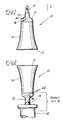
- Figur 1 eine erfindungsgemäße gefüllte, gebrauchsfertige Ampulle in perspektivischer Darstellung;
- Figur 2 eine erfindungsgemäße Ampulle mit zum Aufziehen des Ampulleninhaltes angesetzter Injektionsspritze in perspektivischer Darstellung;
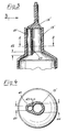
- Figur 3 einen axialen Teilschnitt einer Ampulle in bevorzugter Ausführungsform der Erfindung, wobei der übrige Teil der Ampullenwandung weggelassen ist;
- Figur 4 einen Schnitt nach der Linie A-A der Figur 3;
- Figur 5 eine teilweise Seitenansicht einer Ampulle nach Figur 3 und 4 im Sinne des Pfeiles B in Figur 3;
- Figur 6 eine Draufsicht auf eine Ampulle nach Figur 3 bis 5 im Sinne des Pfeiles C in Figur 5;
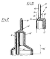
- Figur 7 einen Teilschnitt einer abgewandelten Ausführung nach der Linie D-D in Figur 6 und
- Figur 8 einen Teilschnitt durch eine abgewandelte Ausführung der Ampulle nach der Linie E-E in Figur 6.
- In den in der Zeichnung dargestellten Beispielen ist die Ampulle 10 einstückig aus thermoplastischem Kunststoff, und zwar Polypropylen durch Spritzgießen, hergestellt. Sie weist ein Ampullengefäß 11 auf, das über eine Ampullenschulter 12 in einen Ampullenhals 13 übergeht. An das freie Ende des Ampullenhalses 13 ist ein Verschlußstück 14 angeformt, das durch Abdrehen unter gleichzeitigem Abbrechen und Abreißen entfernbar ist. An dem vom Ampullenhals 13 entfernten Ende ist die Umfangswand des Ampullengefäßes 11 nach dem Füllen flach zusammengepreßt und an einer Verschlußnaht 15 dicht verschweißt.
- Der Ampullenhals 13 ist aufgrund der Herstellung der gesamten Ampulle 10 aus Polypropylen elastisch dehnbar und als Einsteck- und Haltering für den Kopf eines Applikationsgerätes, beispielsweise den Aufnahmekonus 17, einer Injektionsspritze 16 ausgebildet, wobei dieser konische Kopf bzw. Aufnahmekonus 17 zum Aufstecken des eigentlichen Applikators, beispielsweise einer herkömmlichen Injektionsnadel, dient.
- Wie Figur 2 zeigt, wird der Ampullenhals 13 beim Einstecken des konischen Kopfes eines Applikationsgerätes, beispielsweise des Aufnahmekonus 17 einer Injektionsspritze 16 vom freien Ende her elastisch aufgeweitet, so daß sich der Ampullenhals 13 mit seiner Innenfläche fest auf die Außenfläche des konischen Kopfes bzw. des Aufnahmekonus 17 setzt. Das Applikationsgerät, beispielsweise die Injektionsspritze 16 und die aufgesetzte Ampulle 10 bilden dann eine fest zusammengehaltene Einheit, bei der das Aufziehen des Ampulleninhalts auf das Applikationsgerät wesentlich erleichtert ist.
- Bei der in den Figuren 3 bis 6 gezeigten bevorzugten Ausführungsform der Erfindung ist die Belüftungseinrichtung durch ein an den Ampullenhals 13′ einstückig angeformtes, aber separates Belüftungsröhrchen 41 gebildet. Über den Behälterhals 13′ und das Belüftungsröhrchen 41 ist ein gemeinsames Verschlußstück 14′ geformt, so daß beim Abbrechen des Verschlußstückes 14′ gleichzeitig der Behälterhals 13′ und das Belüftungsröhrchen 41 geöffnet werden. Wie Figur 11 zeigt, erstreckt sich das Belüftungsröhrchen 41 parallel zum Ampullenhals 13′ und mündet um eine Strecke 42 tiefer im Ampulleninneren als der Ampullenhals 13, so daß die zwischen dem Ampullenhals 13 und dem Belüftungsröhrchen 41 gebildete Scheidewand 43 sich noch an der Mündung des Ampullenhalses 13 vorbei in das Ampulleninnere erstreckt. Auf diese Weise wird der direkte Übertritt von Luft aus dem Belüftungsröhrchen 41 in den Ampullenhals 13′ und von da in das Applikationsgerät beim Aufziehen des Ampulleninhalts verhindert.
- Um den Übertritt von Luft mit noch größerer Sicherheit zu verhindern, kann in einer abgewandelten Ausführung nach Figur 7 das an den Ampullenhals 13′ angeformte parallele Belüftungsröhrchen 41′ sich auch über eine größere Strecke 42′ über den Ampullenhals 13′ hinaus in das Ampulleninnere erstrecken.
- Wie Figur 4 zeigt, wird das Belüftungsröhrchen 41 bevorzugt mit wesentlichen kleinerem lichtem Querschnitt als der Ampullenhals 13′ ausgebildet. Beispielsweise kann der Durchlaß des Ampullenhalses 13′ etwa doppelten Durchmesser 44 wie der entsprenchende Durchmesser 45 des Belüftungsröhrchens 41 haben.
- Wie die Figuren 3, 7, und 8 zeigen, weist das Verschlußstück 14 einen scheibenförmigen Teil 18 und einen Betätigungsteil 19 auf. Der scheibenförmige Teil 18 des Verschlußstückes 14 ist im Inneren des Mündungsrandbereiches 20 des Behälterhalses 13 angeordnet und über eine den Umfang des scheibenförmigen Teiles 18 umgebende ringförmige Sollbruchstelle 21 mit dem Mündungsrandbereich 20 des Ampullenhalses 13 einstückig verbunden. Auf diese Weise ist der Behälterhals 13 an seinem freien Ende durch den scheibenförmigen Teil 18 des Verschlußstückes 14 und die Sollbruchstelle 21 dicht verschlossen. Durch Abdrehen, Abbrechen und Abreißen des Verschlußstückes 13 wird die Sollbruchstelle 21 zerstört. Nach Entfernen des Verschlußstückes 14 liegt die Mündung des Ampullenhalses 13 frei. Es kann jetzt der Kopf eines Applikationsgerätes, beispielsweise der Aufnahmekonus 17 einer Injektionsspritze, 16 in das offene Ende des Ampullenhalses 13 eingesteckt werden. Um das sichere zügige Einführen dieses Kopfes bzw. Aufnahmekonus 17 zu erleichtern, kann der Mündungsrandbereich 20 des Ampullenhalses nach innen hin im wesentlichen trichterförmig ausgebildet sein. Die in der Zeichnung gezeigten unterschiedlichen Ausführungsformen zeigen Variationen in der Ausbildung dieser trichterförmigen Einführung. Im Beispiel der Figur 8 ist der eigentliche Mündungsrand 25 mit einer Wölbung vorgesehen, deren Krümmungsradius von außen nach innen größer wird, so daß sich ein verstärker gewölbter Trichtereinlaß ergibt. Wie Figur 8 zeigt, liegt die Sollbruchstelle 21 vertieft in dem Mündungsrandbereich 20 des Ampullenhalses 13, so daß der Kopf des Applikationsgerätes bzw. der Aufnahmekonus 17 einer Injektionsspritze 16 bereits in den eigentlichen Mündungsrand 25 des Ampullenhalses 13 eingeführt ist, bevor er die Reste der Sollbruchstelle 21 erreicht.
- Wie Figur 8 ferner zeigt, kann der Betätigungsteil 19 des Verschlußstückes 14 etwa plattenförmig oder laschenförmig ausgebildet sein, um ein sicheres Erfassen zum Abdrehen, Abbrechen und Abreißen des Verschlußstückes 14 zu gewährleisten. Zur weiteren Verbesserung können auf dem Betätigungsteil 19 sich axial erstreckende Griffrippen 31 ausgebildet sein.
- Das Ampullengefäß 11 ist zunächst an seinem dem Ampullenhals 13 entgegengesetzten Ende offen, um es von diesem Ende her zu füllen. Die Umfangswand des Ampullengefäßes 11 hat in Nachbarschaft des Ampullenhalses 13 und der Ampullenschulter 12 größere Dicke als an ihrem offenen Ende.
- Die Umfangswand des Ampullen gehäuses 11 kann durchweg leicht konische sich nach dem offenen Ende hin erweiternde Form und einen der Ampullenschulter 12 benachbarten Teil 32 größerer Dicke 33, beispielsweise von etwa 0,5 mm, haben. In Nachbarschaft des offenen Endes ist ein Teil 34 der Umfangswand mit einer Dicke 35 von etwa 0,35 mm gebildet.
- Bei einer anderen Ausführung ist die Umfangswand des Ampullengefäßes 11 an ihrer Außenseite zylindrisch ausgebildet und weist von der Ampullenschulter 12 her bis zum offenen Ende hin abnehmende Wandstärke, und zwar eine der Ampullenschulter 12 benachbarte Dicke 36, von beispielsweise 0,55 mm und eine Dicke 37 von beispiele 0,35 mm am offenen Ende. Hierdurch verjüngt sich der im Ampullengefäß 11 vor dem Verschließen gebildete Innenraum konisch vom offenen Ende zur Ampullenschulter 12 hin.
- Anstelle der dargestellten Beispiele kann auch vorgesehen sein, die Belüftungseinrichtung völlig getrennt vom Behälterhals 13 an der Ampullenwand, vorzugsweise an der Ampullenschulter 12, vorzusehen. Beispielsweise könnte in Abstand vom Ampullenhals 13 eine leicht durchstoßbare verdünnte Stelle ausgebildet sein. Dies könnte beispielsweise an einer in den Figuren 1 und 2 durch den Pfeil 46 angedeuteten Stelle sein. Es könnte auch an der Stelle 46 ein vom Ampullenhals 13 völlig getrenntes Belüftungsröhrchen in die Ampullenschulter 12 eingeformt sein und ein von dem Ampullenhals 13 getrenntes abbrechbares Verschlußstück tragen.
- Wie die Figuren 1 und 2 zeigen, sind im dargestellten Beispiel auf der Ampullenschulter 12 Blindprägungen 40 angebracht, die Aufschluß über Inhalt und Volumen der Ampulle 10 geben. Diese Blindprägungen 40 sind beim Öffnen der Ampulle 10 und beim Einführen des Aufnahmekonus 17 unübersehbar. Sie sind auch unverwischbar und dadurch geeignet, auch die entleerte Ampulle 10 evtl. noch als Beweisstück für verabreichte Medizin u.dgl. aufzuheben.
Claims (12)
Applications Claiming Priority (2)
| Application Number | Priority Date | Filing Date | Title |
|---|---|---|---|
| DE3818682 | 1988-06-01 | ||
| DE19883818682 DE3818682A1 (de) | 1988-06-01 | 1988-06-01 | Ampulle |
Publications (3)
| Publication Number | Publication Date |
|---|---|
| EP0344476A2 EP0344476A2 (de) | 1989-12-06 |
| EP0344476A3 EP0344476A3 (en) | 1990-03-28 |
| EP0344476B1 true EP0344476B1 (de) | 1992-09-02 |
Family
ID=6355641
Family Applications (1)
| Application Number | Title | Priority Date | Filing Date |
|---|---|---|---|
| EP89107869A Expired - Lifetime EP0344476B1 (de) | 1988-06-01 | 1989-04-29 | Ampulle |
Country Status (8)
| Country | Link |
|---|---|
| US (1) | US4926915A (de) |
| EP (1) | EP0344476B1 (de) |
| JP (1) | JPH0245056A (de) |
| AU (1) | AU3597689A (de) |
| BR (1) | BR8902517A (de) |
| DE (2) | DE3818682A1 (de) |
| ES (1) | ES2034471T3 (de) |
| SU (1) | SU1727518A3 (de) |
Families Citing this family (62)
| Publication number | Priority date | Publication date | Assignee | Title |
|---|---|---|---|---|
| DE3916840A1 (de) * | 1988-09-21 | 1990-03-29 | Bernd Hansen | Ampulle |
| US5409125A (en) * | 1989-12-11 | 1995-04-25 | Aktiebolaget Astra | Unit dose container |
| AU622740B2 (en) * | 1989-12-11 | 1992-04-16 | Astra Aktiebolag | Unit dose container |
| WO1991018640A1 (en) | 1990-06-08 | 1991-12-12 | Ab Astra | Prefilled, disposable device for introducing a pharmacologically active substance into a body cavity of a patient, method for manufacturing said device and mould apparatus for making said device |
| US6540154B1 (en) | 1991-04-24 | 2003-04-01 | Aerogen, Inc. | Systems and methods for controlling fluid feed to an aerosol generator |
| US7628339B2 (en) | 1991-04-24 | 2009-12-08 | Novartis Pharma Ag | Systems and methods for controlling fluid feed to an aerosol generator |
| US5224937A (en) * | 1991-06-21 | 1993-07-06 | Npbi Nederlands Produktielaboratorium Voor Bloedtransfusieapparatuur En Infusievloeistoffen B.V. | Closed syringe-filling system |
| FR2682088B1 (fr) * | 1991-10-04 | 1994-06-10 | Emballages Conditionnement | Conditionnement pour la preparation extemporanee de produits medicamenteux. |
| US5807359A (en) | 1993-06-08 | 1998-09-15 | Bemis Manufacturing Company | Medical suction system |
| DE69528063T2 (de) * | 1994-06-24 | 2003-06-05 | Icu Medical, Inc. | Vorrichtung zur überleitung einer flüssigkeit und methode zur anwendung |
| US5620428A (en) * | 1994-12-29 | 1997-04-15 | Bemis Manufacturing Company | Suction canister apparatus and method |
| US5688255A (en) * | 1994-12-29 | 1997-11-18 | Bemis Manufacturing Company | Method and apparatus for removing and disposing of body fluids |
| US6358232B1 (en) | 1994-12-29 | 2002-03-19 | Bemis Manufacturing Company | Method and apparatus for removing and disposing of body fluids |
| US6244311B1 (en) | 1994-12-29 | 2001-06-12 | Bemis Manufacturing Company | Method and apparatus for removing and disposing of body fluids |
| US5683371A (en) * | 1994-12-29 | 1997-11-04 | Bemis Manufacturing Company | Suction canister apparatus and method |
| US5758637A (en) | 1995-08-31 | 1998-06-02 | Aerogen, Inc. | Liquid dispensing apparatus and methods |
| US6085740A (en) | 1996-02-21 | 2000-07-11 | Aerogen, Inc. | Liquid dispensing apparatus and methods |
| DE29602173U1 (de) * | 1996-02-08 | 1997-06-26 | B. Braun Melsungen Ag, 34212 Melsungen | Applikationsvorrichtung für medizinische Flüssigkeiten |
| SE9702636D0 (sv) * | 1997-07-08 | 1997-07-08 | Pharmacia & Upjohn Ab | Improvements related to medical containers |
| US6082575A (en) * | 1998-03-09 | 2000-07-04 | Pepsico, Inc. | Hybrid beverage container |
| US6235177B1 (en) | 1999-09-09 | 2001-05-22 | Aerogen, Inc. | Method for the construction of an aperture plate for dispensing liquid droplets |
| WO2001072350A1 (en) * | 2000-03-28 | 2001-10-04 | Bemis Manufacturing Company | Medical suction apparatus and methods for draining same |
| US7674248B2 (en) * | 2000-03-28 | 2010-03-09 | Bemis Manufacturing Company | Medical suction apparatus and methods for draining same |
| US7585292B2 (en) * | 2000-03-28 | 2009-09-08 | Bemis Manufacturing Company | Medical suction apparatus and draining of same |
| US7971588B2 (en) | 2000-05-05 | 2011-07-05 | Novartis Ag | Methods and systems for operating an aerosol generator |
| US7100600B2 (en) * | 2001-03-20 | 2006-09-05 | Aerogen, Inc. | Fluid filled ampoules and methods for their use in aerosolizers |
| US8336545B2 (en) | 2000-05-05 | 2012-12-25 | Novartis Pharma Ag | Methods and systems for operating an aerosol generator |
| US7600511B2 (en) | 2001-11-01 | 2009-10-13 | Novartis Pharma Ag | Apparatus and methods for delivery of medicament to a respiratory system |
| MXPA02010884A (es) | 2000-05-05 | 2003-03-27 | Aerogen Ireland Ltd | Aparato y metodo para el suministro de medicamentos al sistema respiratorio. |
| US6948491B2 (en) | 2001-03-20 | 2005-09-27 | Aerogen, Inc. | Convertible fluid feed system with comformable reservoir and methods |
| US6434913B1 (en) * | 2000-09-15 | 2002-08-20 | Thomas Hatch | Single-use syringe |
| US6672477B2 (en) | 2001-01-12 | 2004-01-06 | Bemis Manufacturing Company | Method and apparatus for disposing of bodily fluids from a container |
| US6732944B2 (en) | 2001-05-02 | 2004-05-11 | Aerogen, Inc. | Base isolated nebulizing device and methods |
| MXPA04006629A (es) | 2002-01-07 | 2004-11-10 | Aerogen Inc | Aparatos y metodos para nebulizar fluidos para inhalacion. |
| US7677467B2 (en) | 2002-01-07 | 2010-03-16 | Novartis Pharma Ag | Methods and devices for aerosolizing medicament |
| JP4761709B2 (ja) | 2002-01-15 | 2011-08-31 | エアロジェン,インコーポレイテッド | エアロゾル発生器を作動するための方法およびシステム |
| DE10209990B4 (de) * | 2002-03-07 | 2007-02-08 | Rudolf Gantenbrink | Flasche und Verfahren zu deren Herstellung |
| AU2003256253A1 (en) | 2002-05-20 | 2003-12-02 | Aerogen, Inc. | Aerosol for medical treatment and methods |
| DE10226591B4 (de) * | 2002-06-14 | 2004-10-28 | Rudolf Gantenbrink | Verfahren zum Verschließen eines Hohlkörpers aus Glas, Hohlkörper aus Glas sowie Bausatz |
| USD493526S1 (en) | 2003-04-22 | 2004-07-27 | Becton, Dickinson And Company | Syringe tip cap |
| US8616195B2 (en) | 2003-07-18 | 2013-12-31 | Novartis Ag | Nebuliser for the production of aerosolized medication |
| US20050101922A1 (en) * | 2003-11-07 | 2005-05-12 | Bemis Manufacturing Company | Suction canister and drainage of same |
| US7290541B2 (en) | 2004-04-20 | 2007-11-06 | Aerogen, Inc. | Aerosol delivery apparatus and method for pressure-assisted breathing systems |
| US7267121B2 (en) | 2004-04-20 | 2007-09-11 | Aerogen, Inc. | Aerosol delivery apparatus and method for pressure-assisted breathing systems |
| US7946291B2 (en) | 2004-04-20 | 2011-05-24 | Novartis Ag | Ventilation systems and methods employing aerosol generators |
| EP1726285A1 (de) * | 2005-05-24 | 2006-11-29 | Vifor (International) Ag | Behälter für die Abgabe eines Medikaments und zugehörige Verabreichungsvorrichtung |
| WO2006127181A2 (en) | 2005-05-25 | 2006-11-30 | Aerogen, Inc. | Vibration systems and methods |
| US20070260691A1 (en) * | 2006-05-02 | 2007-11-08 | Kallqvist Claes M | Wireless local area network capacity triggered upload and download |
| US20090318860A1 (en) * | 2006-07-04 | 2009-12-24 | Yoshio Oyama | End Portion Of Hermetically Sealed Container Having Fine Opening Surface Obtained Easily by Cleavage |
| FR2908110B1 (fr) * | 2006-11-03 | 2011-05-20 | Seriplast | Ampoule comportant un corps creux et une tete avec possibilite de rupture entre le corps et la tete. |
| JP5452882B2 (ja) * | 2008-04-30 | 2014-03-26 | 株式会社吉野工業所 | 樹脂製アンプル |
| US8337108B2 (en) * | 2008-06-26 | 2012-12-25 | Elc Management Llc | Single-use cosmetic sampler |
| US9089474B2 (en) | 2012-07-13 | 2015-07-28 | Becton Dickinson and Company Ltd. | Medical vial access device with pressure equalization and closed drug transfer system and method utilizing same |
| JP6452026B2 (ja) * | 2014-07-08 | 2019-01-16 | 大日本印刷株式会社 | 注射剤収納容器、注射剤入り容器、注射剤入り容器の使用方法、および、注射剤収納容器に注射剤を収納する方法 |
| US10179678B2 (en) * | 2017-04-26 | 2019-01-15 | The Hartz Mountain Corporation | Applicator with breakaway cap |
| DE102017007443A1 (de) * | 2017-08-05 | 2019-02-07 | Kocher-Plastik Maschinenbau Gmbh | Blasform-, Füll- und Schließverfahren sowie danach hergestelltes Behältererzeugnis, insbesondere Ampullenerzeugnis |
| DE102017009012A1 (de) * | 2017-09-26 | 2019-03-28 | Kocher-Plastik Maschinenbau Gmbh | Behälter sowie Verbindungs- und Herstellvorrichtung |
| KR101955208B1 (ko) * | 2017-12-18 | 2019-03-07 | 엘앤피코스메틱 (주) | 화장액 보관용 앰플 |
| EP3769745B1 (de) * | 2018-03-23 | 2024-05-01 | TERUMO Kabushiki Kaisha | Wirkstoffgefüllte kunstharzampulle und darin verwendeter kunstharzampullenkörper |
| JP7140615B2 (ja) * | 2018-09-19 | 2022-09-21 | 賢志 根占 | 自動分注装置、自動分注装置の制御方法およびプログラム |
| JP7293185B2 (ja) * | 2019-06-05 | 2023-06-19 | 大日本印刷株式会社 | 注射剤収納用容器、注射剤入り容器、注射剤入り容器の使用方法、および、注射剤収納用容器に注射剤を収納する方法 |
| CN112976543B (zh) * | 2021-02-05 | 2023-01-10 | 抚州市医宝城医疗器械有限公司 | 一种用于生产连排塑料安剖瓶的生产工艺、模具及产品 |
Family Cites Families (20)
| Publication number | Priority date | Publication date | Assignee | Title |
|---|---|---|---|---|
| US1254655A (en) * | 1917-06-14 | 1918-01-29 | Paul Carpenter | Ampul. |
| US1487824A (en) * | 1922-11-11 | 1924-03-25 | Charles W Vincent | Funnel |
| US1641328A (en) * | 1925-06-06 | 1927-09-06 | Ferdinand Jules Alfred | Dosing flask |
| US1651963A (en) * | 1926-05-18 | 1927-12-06 | Mooney Jerome Henry | Funnel |
| US2668533A (en) * | 1952-02-12 | 1954-02-09 | Sterilon Corp | Medical apparatus |
| FR1066799A (fr) * | 1952-11-25 | 1954-06-09 | Tube pour matières pâteuses ou autres, procédé de fabrication de ce tube et moule pour la mise en oeuvre du procédé ou procédé similaire | |
| US2798488A (en) * | 1954-09-15 | 1957-07-09 | Merck & Co Inc | Syringe unit |
| US2878808A (en) * | 1957-03-26 | 1959-03-24 | Baxter Laboratories Inc | Parenteral solution container closure |
| NL272321A (de) * | 1960-12-09 | |||
| DE1966623B2 (de) * | 1969-01-02 | 1976-08-26 | Ausscheidung aus: 19 65 761 Arias, Marcelo Chiquiar, Dr., Mexiko | Zur einmaligen benutzung bestimmte vorrichtung fuer die ausgabe einer dosis von verunreinigungsempfindlichen behandlungsfluessigkeiten |
| US3667657A (en) * | 1969-01-02 | 1972-06-06 | Marcelo Chiqular Arias | Disposable container |
| US3777949A (en) * | 1969-09-29 | 1973-12-11 | Arias M Chiquiari | Improved single dose disposable container and accessories |
| DE2142735A1 (de) * | 1970-08-27 | 1972-04-13 | TJ. Smith & Nephew Ltd., Hull, Yorkshire (Großbritannien) | Behälterdüse und Behälter |
| DE2653993C3 (de) * | 1976-11-27 | 1980-05-14 | Stella-Kg Werner Deussen, 6229 Walluf | Behälter mit abbrechbarem Verschluß |
| SE412697B (sv) * | 1978-09-13 | 1980-03-17 | Gambro Dialysatoren | Anslutningsnippel for blodpasar eller liknande |
| US4338980A (en) * | 1980-01-14 | 1982-07-13 | Schwebel Paul R | Device for filling medicament injectors |
| DE88056T1 (de) * | 1982-02-08 | 1984-03-01 | Astra Laekemedel Ab, 15185 Soedertaelje | Mit normaldosis gefuellter behaelter. |
| AT386123B (de) * | 1986-05-26 | 1988-07-11 | Pharmazeutische Fabrik Montavit Gmbh | Behaelter aus kunststoff zur aufbewahrung und applikation eines kathetergleitmittels |
| GB8801655D0 (en) * | 1988-01-26 | 1988-02-24 | Waverley Pharma Ltd | Ampoules |
| GB8802349D0 (en) * | 1988-02-03 | 1988-03-02 | Waverley Pharma Ltd | Ampoule with luer |
-
1988
- 1988-06-01 DE DE19883818682 patent/DE3818682A1/de not_active Withdrawn
- 1988-07-18 US US07/220,593 patent/US4926915A/en not_active Expired - Fee Related
-
1989
- 1989-04-29 EP EP89107869A patent/EP0344476B1/de not_active Expired - Lifetime
- 1989-04-29 ES ES89107869T patent/ES2034471T3/es not_active Expired - Lifetime
- 1989-04-29 DE DE8989107869T patent/DE58902185D1/de not_active Expired - Fee Related
- 1989-05-30 SU SU894614233A patent/SU1727518A3/ru active
- 1989-05-31 AU AU35976/89A patent/AU3597689A/en not_active Abandoned
- 1989-06-01 JP JP1137591A patent/JPH0245056A/ja active Granted
- 1989-06-01 BR BR8902517A patent/BR8902517A/pt unknown
Also Published As
| Publication number | Publication date |
|---|---|
| DE58902185D1 (de) | 1992-10-08 |
| ES2034471T3 (es) | 1993-04-01 |
| BR8902517A (pt) | 1990-01-23 |
| JPH0588619B2 (de) | 1993-12-22 |
| SU1727518A3 (ru) | 1992-04-15 |
| EP0344476A3 (en) | 1990-03-28 |
| AU3597689A (en) | 1989-12-07 |
| JPH0245056A (ja) | 1990-02-15 |
| DE3818682A1 (de) | 1989-12-21 |
| EP0344476A2 (de) | 1989-12-06 |
| US4926915A (en) | 1990-05-22 |
Similar Documents
| Publication | Publication Date | Title |
|---|---|---|
| EP0344476B1 (de) | Ampulle | |
| DE69110112T2 (de) | Ausgabefläschchen mit Ärmeln. | |
| DE69915165T2 (de) | Versiegelter Behälter mit Düse und Dichtwulst | |
| DE69403452T2 (de) | Verschluss für medizinbehälter | |
| DE69515885T2 (de) | Behälter für pharmazeutische Produkte mit zwei gesonderten Komponenten, mit Mitteln zu deren Mischung und dosierter Ausgabe sowie Verfahren zum Zusammenstellen des Behälters | |
| DE69627420T2 (de) | Verschlusskappe mit einem Dränierungsdorn zur Verwendung mit einem hermetisch abgedichteten Ausgabebehälter | |
| DE69513567T2 (de) | Hermetisch abgedichteter Behälter mit einem Drehmomenten widerstehenden Verschluss | |
| EP0312725B1 (de) | Tropferflasche und Verfahren zu ihrer Herstellung | |
| DE2653993C3 (de) | Behälter mit abbrechbarem Verschluß | |
| DE10127823C1 (de) | Verschluss für eine Medikamentenflasche sowie Verfahren zu dessen Herstellung | |
| DE69705589T2 (de) | Verpackung für biologische Flüssigkeiten mit aufreissbarer Folie zur Einführung einer Sonde | |
| CH692194A5 (de) | Verpackung. | |
| DE10139291A1 (de) | Filterverpackung | |
| EP0364783A1 (de) | Verschluss für eine Medikamentenflasche und Verfahren zur Herstellung dieses Verschlusses | |
| DE19832834A1 (de) | Sicherheits-Infusions-Katheternadel | |
| EP0383131B1 (de) | Kollabierbarer Behälter zur Aufnahme von flüssigen Substanzen | |
| EP1239963A2 (de) | Verschlussvorrichtung für einen unterdruck-probensammelbehälter | |
| DE1491627A1 (de) | Veneninfusionsgeraet und Zufuehreinrichtung fuer dasselbe | |
| EP0147507A2 (de) | Originalitätsgesicherte Verschlussanordnung | |
| DE69030117T2 (de) | Behälter für einheitsdosis | |
| CH615129A5 (de) | ||
| EP3519315A1 (de) | Verschlusskappe für ein behältnis zum aufnehmen einer medizinischen flüssigkeit | |
| AT404556B (de) | Einrichtung zum dichten verschliessen eines glas- oder kunststoffbehälters zur aufnahme flüssiger pharmazeutischer produkte | |
| DE3005985A1 (de) | Behaelterverschluss | |
| DE3716586C2 (de) | Behälter aus Kunststoff zur Aufbewahrung und Applikation eines Kathetergleitmittels und Verfahren zu seiner Herstellung |
Legal Events
| Date | Code | Title | Description |
|---|---|---|---|
| PUAI | Public reference made under article 153(3) epc to a published international application that has entered the european phase |
Free format text: ORIGINAL CODE: 0009012 |
|
| AK | Designated contracting states |
Kind code of ref document: A2 Designated state(s): DE ES FR GB IT |
|
| PUAL | Search report despatched |
Free format text: ORIGINAL CODE: 0009013 |
|
| AK | Designated contracting states |
Kind code of ref document: A3 Designated state(s): DE ES FR GB IT |
|
| 17P | Request for examination filed |
Effective date: 19900727 |
|
| 17Q | First examination report despatched |
Effective date: 19911025 |
|
| GRAA | (expected) grant |
Free format text: ORIGINAL CODE: 0009210 |
|
| RAP3 | Party data changed (applicant data changed or rights of an application transferred) |
Owner name: DEUSSEN KUNSTSTOFFTECHNIK INHABER HEINO DEUSSEN |
|
| AK | Designated contracting states |
Kind code of ref document: B1 Designated state(s): DE ES FR GB IT |
|
| ITF | It: translation for a ep patent filed | ||
| REF | Corresponds to: |
Ref document number: 58902185 Country of ref document: DE Date of ref document: 19921008 |
|
| GBT | Gb: translation of ep patent filed (gb section 77(6)(a)/1977) | ||
| ET | Fr: translation filed | ||
| REG | Reference to a national code |
Ref country code: ES Ref legal event code: FG2A Ref document number: 2034471 Country of ref document: ES Kind code of ref document: T3 |
|
| PLBE | No opposition filed within time limit |
Free format text: ORIGINAL CODE: 0009261 |
|
| STAA | Information on the status of an ep patent application or granted ep patent |
Free format text: STATUS: NO OPPOSITION FILED WITHIN TIME LIMIT |
|
| 26N | No opposition filed | ||
| PGFP | Annual fee paid to national office [announced via postgrant information from national office to epo] |
Ref country code: FR Payment date: 19960215 Year of fee payment: 8 |
|
| PGFP | Annual fee paid to national office [announced via postgrant information from national office to epo] |
Ref country code: GB Payment date: 19960412 Year of fee payment: 8 |
|
| PGFP | Annual fee paid to national office [announced via postgrant information from national office to epo] |
Ref country code: ES Payment date: 19960430 Year of fee payment: 8 |
|
| PGFP | Annual fee paid to national office [announced via postgrant information from national office to epo] |
Ref country code: DE Payment date: 19960614 Year of fee payment: 8 |
|
| PG25 | Lapsed in a contracting state [announced via postgrant information from national office to epo] |
Ref country code: GB Effective date: 19970429 |
|
| PG25 | Lapsed in a contracting state [announced via postgrant information from national office to epo] |
Ref country code: ES Free format text: LAPSE BECAUSE OF THE APPLICANT RENOUNCES Effective date: 19970430 |
|
| GBPC | Gb: european patent ceased through non-payment of renewal fee |
Effective date: 19970429 |
|
| PG25 | Lapsed in a contracting state [announced via postgrant information from national office to epo] |
Ref country code: FR Free format text: LAPSE BECAUSE OF NON-PAYMENT OF DUE FEES Effective date: 19971231 |
|
| PG25 | Lapsed in a contracting state [announced via postgrant information from national office to epo] |
Ref country code: DE Free format text: LAPSE BECAUSE OF NON-PAYMENT OF DUE FEES Effective date: 19980101 |
|
| REG | Reference to a national code |
Ref country code: FR Ref legal event code: ST |
|
| REG | Reference to a national code |
Ref country code: ES Ref legal event code: FD2A Effective date: 19991102 |
|
| PG25 | Lapsed in a contracting state [announced via postgrant information from national office to epo] |
Ref country code: IT Free format text: LAPSE BECAUSE OF NON-PAYMENT OF DUE FEES;WARNING: LAPSES OF ITALIAN PATENTS WITH EFFECTIVE DATE BEFORE 2007 MAY HAVE OCCURRED AT ANY TIME BEFORE 2007. THE CORRECT EFFECTIVE DATE MAY BE DIFFERENT FROM THE ONE RECORDED. Effective date: 20050429 |