EP1548743B1 - Semiconductor readout circuit - Google Patents
Semiconductor readout circuit Download PDFInfo
- Publication number
- EP1548743B1 EP1548743B1 EP04258043A EP04258043A EP1548743B1 EP 1548743 B1 EP1548743 B1 EP 1548743B1 EP 04258043 A EP04258043 A EP 04258043A EP 04258043 A EP04258043 A EP 04258043A EP 1548743 B1 EP1548743 B1 EP 1548743B1
- Authority
- EP
- European Patent Office
- Prior art keywords
- circuit
- voltage
- readout
- bit line
- precharge
- Prior art date
- Legal status (The legal status is an assumption and is not a legal conclusion. Google has not performed a legal analysis and makes no representation as to the accuracy of the status listed.)
- Expired - Fee Related
Links
Images


Classifications
-
- G—PHYSICS
- G11—INFORMATION STORAGE
- G11C—STATIC STORES
- G11C16/00—Erasable programmable read-only memories
- G11C16/02—Erasable programmable read-only memories electrically programmable
- G11C16/06—Auxiliary circuits, e.g. for writing into memory
- G11C16/24—Bit-line control circuits
-
- G—PHYSICS
- G11—INFORMATION STORAGE
- G11C—STATIC STORES
- G11C16/00—Erasable programmable read-only memories
- G11C16/02—Erasable programmable read-only memories electrically programmable
- G11C16/06—Auxiliary circuits, e.g. for writing into memory
- G11C16/26—Sensing or reading circuits; Data output circuits
- G11C16/28—Sensing or reading circuits; Data output circuits using differential sensing or reference cells, e.g. dummy cells
-
- G—PHYSICS
- G11—INFORMATION STORAGE
- G11C—STATIC STORES
- G11C16/00—Erasable programmable read-only memories
- G11C16/02—Erasable programmable read-only memories electrically programmable
- G11C16/06—Auxiliary circuits, e.g. for writing into memory
- G11C16/30—Power supply circuits
-
- G—PHYSICS
- G11—INFORMATION STORAGE
- G11C—STATIC STORES
- G11C5/00—Details of stores covered by group G11C11/00
- G11C5/14—Power supply arrangements, e.g. power down, chip selection or deselection, layout of wirings or power grids, or multiple supply levels
- G11C5/147—Voltage reference generators, voltage or current regulators; Internally lowered supply levels; Compensation for voltage drops
-
- G—PHYSICS
- G11—INFORMATION STORAGE
- G11C—STATIC STORES
- G11C7/00—Arrangements for writing information into, or reading information out from, a digital store
- G11C7/06—Sense amplifiers; Associated circuits, e.g. timing or triggering circuits
- G11C7/062—Differential amplifiers of non-latching type, e.g. comparators, long-tailed pairs
-
- G—PHYSICS
- G11—INFORMATION STORAGE
- G11C—STATIC STORES
- G11C7/00—Arrangements for writing information into, or reading information out from, a digital store
- G11C7/12—Bit line control circuits, e.g. drivers, boosters, pull-up circuits, pull-down circuits, precharging circuits, equalising circuits, for bit lines
Definitions
- the present invention relates to a semiconductor device, in particular, a semiconductor memory device. More specifically, the invention relates to a semiconductor readout circuit capable of reading out data in a memory cell of a semiconductor device at a high speed.
- nonvolatile memories that are electrically rewritable
- various nonvolatile memories such as an EEPROM, a flash EEPROM (hereinafter, flash memory), an SW memory (side wall memory) where a memory cell has a electric charge keeping area at the side of a control gate, and so forth are present and disclosed.
- These nonvolatile memories are in common in that data is memorized into a memory cell and read out therefrom.
- memory cells There are various structures in memory cells, and for example, in a flash memory, a MOSFET equipped with a floating gate is used as a memory cell.
- the threshold voltage of a transistor changes according to the electric charge accumulation condition of a floating gate of this memory cell, and this threshold value are memorized as data.
- a predetermined readout voltage is impressed via a bit line to the drain of a selected memory cell by a word line connected to the control gate of the memory cell, and the bit line connected to the drain of the memory cell, and changes in memory cell current owing to the difference in the sizes of the threshold voltage of the memory cell transistor, i.e., changes in the current of the bit line connected to the memory cell are detected and amplified by a circuit such as a sense amplifier or so, thereby data is read out.
- Fig. 15 shows a memory cell readout circuit 100 according to the conventional art.
- the readout circuit 100 comprises a feedback-type bias circuit 101, a load circuit 102, and a comparator circuit 103, to the memory array 104.
- the readout circuit 100 shown in Fig. 15 will be briefly described hereinafter.
- the memory array 104 is structured by flash memory cells
- the word line WL and the bit line BL the memory cell as a readout objective in the memory array 104 is selected.
- the bit line voltage is supposed to be at GND level (ground voltage).
- GND level ground voltage
- the bit line BL of the memory cell to be read out is selected by the bit line selection transistor 105
- charging of the selected bit line BL is started via charging of the node N2 by the load circuit 102.
- the bit line voltage is kept at a predetermined voltage, and the voltage of the readout input node N1 is determined according to the current flowing through memory cells and the voltage-current characteristics of the load circuit 102.
- the voltage of the readout input node N1 changes according to the current flowing through memory cells.
- the current flowing memory cells in the case of a flash memory, changes according to threshold voltage, therefore the voltage of the readout input node N1 changes according to the threshold voltage of the flash memory.
- the reference voltage Vref with respect to the voltage of the readout input node N1 is set to a voltage at which changes in a voltage of the readout input node N1 can be judged in the comparator circuit 103.
- the intermediate voltage between the voltages of the readout input node N1 when the threshold voltage of the memory cell is high and low resepectively is made as the reference voltage Vref.
- the readout input node N1 When the threshold voltage is low and memory cell current flows, the readout input node N1 outputs a voltage which is lower than the reference voltage Vref, and when the threshold voltage is high and the memory cell current does not flow, the readout input node N1 outputs a voltage which is higher than the reference voltage Vref. As a result, by the comparator circuit 103, it is judged whether the voltage of the readout input node N1 is higher or lower than the reference voltage Vref, thereby the size of the threshold voltage of the memory cell is judged.
- a readout input node N1 when the current supply capacity of the load circuit 102 is large with respect to the memory cell current, i.e., the bit line current, the voltage difference, which is output to the readout input node N1, between the voltage when the memory cell current is large and the voltage when the memory cell current is small becomes small, causing difficulty in reading data at high speed
- the current supply capacity of the load circuit cannot be too large.
- the bit line capacity is large, it takes time to attain a bit line voltage preferable for readout causing the memory cell readout time being longer.
- the bit line becomes long, and its capacity becomes large accordingly, therefore, there is a demand for a readout circuit which can conduct memory cell readout operations at a high speed, even when the bit line capacity is large.
- precharge circuit a bit line charge circuit
- Fig. 16 shows an example of a memory cell readout circuit including a precharge circuit disclosed in JP-A 2000-311493 .
- a memory cell readout circuit 110 comprises a feedback-type bias circuit 111, a load circuit 112, and a precharge circuit 113.
- a precharge circuit 113 By the way, for simplicity of explanations, only one of memory cells 115 in a memory cell is shown therein.
- the operation principle of the memory cell readout circuit 110 is that a bit line BL is charged at a high speed by the precharge circuit 113 which has a sufficiently larger current supply capacity than that of the load circuit 112, and when the bit line is charged up to a certain voltage, the operation of the precharge circuit 113 is stopped, and by the load circuit 112 and the feedback-type bias circuit 111, changes of the memory cell current are converted into voltage changes in the readout input node N1, and in a comparator circuit 114, the voltage changes are compared with the reference voltage Vref, and readout operations are carried out.
- the precharge circuit 113 which has a sufficiently larger current supply capacity than that of the load circuit 112
- a pulse signal which is generated on the basis of a timing signal generated by an address transition detection circuit and the like (ATDP signal)
- the activation period (precharge period) of the precharge circuit 113 is determined
- the feedback bias circuit 111 the hold voltage of the bit line BL is determined.
- Fig. 17 shows an example of a circuit which generates an ATDP signal.
- Fig. 18 shows an example of a readout circuit of the same concept as that in Fig. 16 .
- a readout circuit 120 in Fig. 18 has a same circuit configuration as the readout circuit 100 in Fig. 15 except that it is equipped with a precharge circuit 121 which works only for a predetermined precharge period.
- the difference between the readout circuit 120 in Fig. 18 and the readout circuit 110 in Fig. 16 is the circuit characteristic of the feedback-type bias circuit 101.
- the output change ratio of the gate voltage of a transfer gate 106 comprising an N-type MOSFET to the voltage of the node N2 appears larger in the feedback-type bias circuit 101 in Fig. 18 .
- the behaviors of the transfer gate 117 to the voltage of the node N2 in the readout circuit 110 in Fig. 16 correspond to that of the transfer gate 106 to the voltage of the node N2 in the readout circuit 120 in Fig. 18 .
- the readout circuit 120 in Fig. 18 in the same manner as the readout circuit 110 in Fig. 16 , carries out charging operations, up to a bit line hold voltage which is determined by the feedback-type bias circuit 101, while the precharge signal PRC of the precharge circuit 121 is at an "H" (high) level (for precharge period).
- the precharge signal PRC is at an "H" level
- the charge operations of the bit line BL by the precharge circuit 121 stop, and the bit line BL is not charged up to the bit line hold voltage or higher.
- the transfer gate 106 is also turned OFF.
- This state is the state where the charge of the bit line BL is completed.
- the operation of the precharge circuit 121 is stopped, in the case when the threshold voltage of the memory cell selected by the bit line selection transistor 105 is low, and in the case when the word line connected to the memory cell is selected, the charge level of the bit line BL is lowered by the memory cell voltage. Namely, the voltage of the node N2 falls. As the voltage of the node N2 falls, the voltage of the node N3 which is the gate input of the transfer gate 106 rises, and the transfer gate 106 shifts from an OFF state to an ON state.
- the readout input node N1 changes into the voltage which is determined by the current which flows when the transfer gate 106 is turned into an ON state, and the load current that the load circuit 102 flows.
- the load circuit 102 as shown in Fig. 19 , there is a load circuit which uses a P-type MOSFET which uses a predetermined bias voltage as gate voltage.
- FIG. 20 the current-voltage characteristic of the load circuit using the P-type MOSFET is shown in (a), and the current-voltage characteristic in the state where the transfer gate 106 is in an ON state (the state where the threshold voltage of the memory cell is low, and the cell current is large) is shown in (b), and the current-voltage characteristic in the state where the transfer gate 106 is roughly in an OFF state (the state where the threshold voltage of the memory cell is high, and the cell current is small) is shown in (c).
- the threshold voltage of the selected memory cell when the threshold voltage of the selected memory cell is high, the current which flows from the bit line BL to the memory cell is small, and the voltage level of the node N2 hardly falls, and the transfer gate 106 remains in an almost OFF state (or in a slightly ON state).
- the DC voltage VN1H of the readout input node N1 in the case when the threshold voltage of the memory cell determined by the characteristic (a) and the characteristic (c) is high, is given by the voltage value at the cross point of the characteristic (a) and the characteristic (c). Therefore, when the threshold voltage of the selected memory cell is high, the readout input node N1 shifts from the level at completion of precharge of the bit line BL to the voltage VN1H.
- the current-voltage characteristic of the load circuit 102 is characterized as shown in (a) of Fig. 20 , the readout input node N1 appropriately changes according to the threshold voltage of the memory cell.
- the operation of the precharge circuit 121 is continued.
- the voltage of the bit line BL is maintained at the bit line hold voltage, but, because the transfer gate 106 of the feedback-type bias circuit 101 is in a roughly OFF state, the readout input node N1 is charged by the load circuit, and the voltage thereof rises higher than the voltage at completion of the bit line charge. If the transfer gate 106 is being OFF state for a long time after the precharge circuit 121 starts operating and the bit line charge is complete, the voltage of the readout input node N1 rises to the maximum power source voltage.
- the operation of the precharge circuit is stopped, and when the threshold voltage of the selected memory cell is low and the bit line current starts flowing according to the memory cell condition, the voltage of the readout input node N1 changes to the voltage VN1L.
- the readout input node N1 does not change rapidly to the voltage VN1L.
- the bit line length is long so as to make the chip size small, as a result, its bit line resistance and bit line capacity become large. Accordingly, even when the transfer gate 106 is turned into an ON state, because the bit line resistance and the bit line capacity are large, it takes time to shift to the voltage VN1L.
- Figs. 21 and 22 examples of the comparators 103 are shown.
- a differential amplifier using an N-type MOSFET as an input device is used as a comparator circuit
- a differential amplifier using a P-type MOSFET as an input device is used as a comparator circuit.
- both comparators in Figs. 21 and 22 when the input voltage is input near the power source voltage, even if there is a voltage difference between the reference voltage Vref and the voltage of the readout input node N1, output is not carried out at a high speed.
- Vref the reference voltage difference between the reference voltage Vref and the voltage of the readout input node N1
- the voltage value is not necessarily the same, and is different from the voltage value of the bias of the load circuit in Fig. 19 .
- the input voltage of the comparator circuit 103 needs to be at optimized voltage with which comparator circuits can operate at high speed.
- the voltage of the readout input node N1 will rise by the load circuit 102.
- the operation of the precharge circuit 121 may be stopped.
- a method to solve the above problem is disclosed in Fig. 3 of JP-A 2000- 311493 .
- the circuit thereof is shown in Fig. 23 .
- a memory cell readout circuit 130 shown in Fig. 23 in comparison with the memory cell readout circuit 110 in Fig. 16 , is equipped with a second transfer gate 131 comprising an N-type MOSFET which short-circuits between the readout input node N1 and a gate node N3 of a transfer gate 117 of a feedback-type bias circuit 111.
- US 5671186 discloses a semiconductor memory device that includes a bit line, a memory cell, and a precharge circuit responsive to a precharge signal for charging the bit line.
- the precharge circuit is enabled before cell data is read from the memory cell via the precharged bit line.
- the memory device further includes a potential controller responsive to the precharge signal for regulating the charge applied to the bit line by the precharge circuit.
- a charge supplying circuit is coupled to the bit line, and maintains the bit line potential at a predetermined voltage level by providing the bit line with charges during a period from when the precharge circuit completes its precharge operation to when the bit line potential changes in response to reading data from the memory cell.
- EP 1 049 102 discloses a non-volatile semiconductor memory device capable of shortening time required for determining a reading voltage in its reading circuit and of improving a data reading speed.
- the non-volatile semiconductor memory device has a feedback-type bias circuit for letting currents to flow, in response to a first timing signal occurring when an address of a memory cell is selected from a load circuit to the memory cell to be connected to a bit line through a bit line decoder according to selection of the address and to be connected through a word line, causing a predetermined bias current to be supplied to the bit line and for letting a current to flow in accordance with an ON state or OFF state of the memory cell, causing a reading voltage to be produced at a connection point with the load circuit and a precharging circuit for letting currents to flow through the bit line in response to a second timing signal occurring in an early stage when the first timing signal is active and for interrupting currents flowing through the bit line in a last stage when the second timing signal is active.
- the present invention has been made in view of the above problems, and it is therefore an object of the invention to provide a semiconductor readout circuit capable of effectively reading out memory cell data at a high speed even in the case where capacity and resistance of a bit line are large.
- a semiconductor readout circuit is defined in claim 1.
- a circuit configuration according to the first aspect includes the following configurations: the precharge circuit charges the bit lines via the node and the bit line selecting MOSFETs, and the feedback-type bias circuit controls the voltage of the bit lines via the node and the bit line selecting MOSFETs. Therefore, one end of the transfer gate of the feedback-type bias circuit is the readout input node, while the other end thereof is a node that the precharge circuit directly charges, and the node is connected to the bit lines via the bit line selecting MOSFETs.
- start of a period when the load circuit is made inactive is set to at latest upon or in the vicinity of a time when the charging of the bit lines is completed, so that the readout input node can be prevented from being charged to an unnecessarily high voltage from the level upon completion of the charging of the bit lines.
- the load circuit is made active at the same timing, so that it is possible to shift to the voltage of the readout input node according to the cell current corresponding to the memory state of the memory cell at a high speed.
- the sense amplifier is constituted of a comparator circuit which has a voltage of the readout input node and a predetermined reference voltage as differential inputs.
- the semiconductor readout circuit comprises a reference voltage generation circuit which generates the reference voltage.
- the reference voltage generation circuit includes : a reference load circuit having the same circuit configuration as that of the load circuit; a reference precharge circuit having the same circuit configuration as that of the precharge circuit; a reference feedback-type bias circuit having the same circuit configuration as that of the feedback-type bias circuit; and a reference cell having the same element structure as that of the memory cell.
- the reference voltage when the reference cell is set to have an intermediate current within a fluctuation range of the cell current of the memory cell, the reference voltage can be set to have an intermediate voltage value within a fluctuation range of the voltage of the readout input node.
- the comparator circuit compares the reference voltage with the voltage of the readout input node as differential inputs, it is possible to reliably perform a readout operation of a memory cell corresponding to an amount of cell currents of the memory cell at a high speed.
- the reference voltage generation circuit when the reference voltage generation circuit is designed to have the same configuration as those of the circuits in a readout system from a charge circuit to a memory cell, an operation margin can be maintained widely because the reference voltage and the voltage of the readout input node change according to changes in an operation voltage, an operation temperature, variation of a manufacturing process and the like.
- the reference voltage generation circuit is constituted of a pair of a first reference voltage generation circuit in which a cell current of the reference cell is set to a cell current corresponding to one memory state of the memory cell and a second reference voltage generation circuit in which the cell current of the reference cell is set to a cell current corresponding to another memory state of the memory cell, and a first reference voltage generated from the first reference voltage generation circuit and a second reference voltage generated from the second reference voltage generation circuit are input in parallel with each other on one side of the differential inputs of the comparator circuit.
- the first reference voltage and the second reference voltage reflect two voltage values corresponding to memory states of the memory cell.
- the reference cell when both reference voltages are input in parallel with each other to one side of the differential inputs of the comparator circuit, the reference cell can be substantially set to have an intermediate current within a fluctuation range of the cell current of the memory cell, so that working effects in the second aspect can be exhibited.
- the reference cell since cell currents of two reference cells can be set in the same manner as in cell currents of the respective memory cells, the reference cell can have the same setting conditions as programming conditions of a normal memory cell; therefore, it is unnecessary to provide a special setting condition.
- the voltage of the readout input node in a period before the bit line current flows and the memory cell readout starts after completion of charging of the bit line can be set at an optimal level for operations of the sense amplifier at the subsequent stage thereof.
- the sense amplifier can carry out a high speed output operation according to voltage changes of the readout input node corresponding to an amount of cell currents.
- the hold circuit includes an N-type MOSFET where a source connected to the readout input node, a drain connected to a power supply voltage, and a gate connected to a predetermined intermediate voltage for determining the hold voltage. More preferably, the intermediate voltage is supplied from an internal node of the feedback-type bias circuit or the intermediate voltage is determined by a circuit constant in the feedback-type bias circuit as an intermediate voltage between the gate voltage of the transfer gate from the internal node in the feedback-type bias circuit and the power supply voltage. With this configuration, the hold voltage of the readout input node can be adjusted by adjusting the intermediate voltage.
- the load circuit is constituted by use of a P-type MOSFET capable of controlling an amount of currents supplied from the load circuit by the bias voltage input to the gate, and the bias voltage is adjusted so that the amount of currents of the P-type MOSFET is within a range of a memory cell current which changes according to the information stored in the memory cell.
- the amount of currents of the P-type MOSFET is within a range of the memory cell currents, when the bit line current flows and the load circuit is made active, an amount of load currents of the lord circuit does not excessively become large or small with respect to the memory cell current, so that the voltage of the readout input node can promptly shift to a voltage value according to an amount of memory cell currents.
- the above configuration contributes to a high-speed readout operation of the sense amplifier.
- the semiconductor readout circuit comprises a bias voltage generation circuit which generates the bias voltage
- the bias voltage generation circuit includes: a bias voltage generating reference cell; and a second load circuit which flows the same amount of load currents as that of cell currents of the bias voltage generating reference cell, and can control an amount of load currents of the load circuit according to the amount of load currents, and the cell current of the bias voltage generating reference cell is set at an intermediate level between two cell currents corresponding to each memory states of the memory cell.
- the bias voltage is adjusted so that the amount of currents of the P-type MOSFET is within the range of the memory cell current which changes according to the information stored in the memory cell; thus, working effects according to the fourth aspect can be specifically exhibited.
- the semiconductor readout circuit further comprises a precharge signal generation circuit which generates a precharge signal for making the precharge circuit active
- the precharge signal generation circuit includes: a dummy bit line which simulates the bit line; a dummy precharge circuit which can charge the dummy bit line by the same charge current as that of the precharge circuit to the same charge voltage; a dummy feedback-type bias circuit which has the same circuit configuration as that of the feedback-type bias circuit for controlling a voltage of the dummy bit line so as to be a predetermined voltage; and a dummy load circuit which can charge a dummy readout input node connected to the dummy bit line via a transfer gate of the dummy feedback-type bias circuit by the same charge current as that of the load circuit.
- the precharge signal generation circuit detects a charge state of the dummy bit line and stops generating the precharge signal on the basis of the voltage of the dummy readout input node.
- the dummy bit line when the dummy bit line is structured by suitably simulating parasitic capacity or parasitic resistance of the bit line, the following effects can be exhibited: a charging state of the bit line can be monitored by a change in voltage of the dummy bit line, termination of the precharge period when the precharge circuit is active can be automatically set at a completion timing of charging of the bit line, and a memory cell readout operation can be promptly performed after completion of charging of the bit line. Consequently, it is possible to promote a high-speed readout operation of a voltage of the readout input node by the sense amplifier. Basically, parasitic capacity and parasitic resistance of a dummy bit line is equivalent to those of the bit line.
- the timing adjustment of the precharge period is needed, by adjusting the parasitic capacity and parasitic resistance of the dummy bit line, i.e., the length of the dummy bit line and the number of dummy memory cells to be connected, the timing can be adjusted.
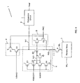
- Fig. 1 is a circuit diagram showing a circuit configuration of an inventive circuit 1.
- the inventive circuit 1 comprises a feedback-type bias circuit 2, a load circuit 3, a comparator circuit 4, a precharge circuit 5, and a hold circuit 6 of a readout input node N1.
- a memory array 7 has a structure in that memory cells are arranged in an array form.
- Fig. 1 shows for simplifying the figure one word line WL and one bit line BL for selecting a memory cell to be read out in the memory array 7. Therefore, the inventive circuit 1 may be a flash memory wherein memory cells in the memory array 7 are flash memory cells, and a flash memory may be used as a semiconductor device that includes the inventive circuit 1.
- the feedback-type bias circuit 2 is structured so as to control a node N2 connected to the bit line BL via a bit line selection transistor 8 comprising an N-type MOSFET (hereinafter, referred to as NMOS) at a predetermined voltage, and control the voltage of the indirectly selected bit line BL at the predetermined voltage.
- a bit line selection transistor 8 comprising an N-type MOSFET (hereinafter, referred to as NMOS) at a predetermined voltage
- the feedback-type bias circuit is equipped with a transfer gate 20 having an NMOS whose drain is connected to the readout input node N1 connected to one side of differential inputs of the comparator circuit 4, source is connected to the node N2, and gate is connected to an internal node N3, a series circuit of two P-type MOSFETs (hereinafter, referred to as PMOSs) 21 and 22 arranged between the power source voltage (power source line) and an internal node N3, and a series circuit of two NMOSs 23 and 24 arranged between the internal node N3 and a GND voltage (ground line).
- PMOSs P-type MOSFETs
- the source thereof is connected to the power source voltage
- the drain is connected to the source of the other PMOS 22, and the gate is connected to the node N2
- the source thereof is connected to the drain of the PMOS 21
- the drain is connected to the internal node N3, and the gate is connected to a control signal FBBOFF
- the NMOS 23 the drain thereof is connected to the internal node N3, the source is connected to the drain of the other NMOS 24, and the gate is connected to a control signal SAEN, while in the other NMOS 24, the drain thereof is connected to the source of the NMOS 23, the source is connected to the GND voltage (ground line), and the gate is connected to the node N2.
- an NMOS 25 is arranged wherein a gate that fixes the internal node N3 to GND voltage when the feedback-type bias circuit 2 is OFF is connected to the control signal FBBOFF.
- the load circuit 3 is a circuit that charges the readout input node N1 with a predetermined load current (charge current), and includes a series circuit of PMOSs 31 and 32 arranged between the power source voltage (power source line) and the readout input node N1.
- the source thereof is connected to the power source voltage (power source line)
- the drain is connected to the source of the PMOS 32
- the gate is connected to a precharge signal PRC to be described later herein
- the source thereof is connected to the drain of the PMOS 31
- the drain is connected to the readout input node N1, and the drain is connected to a predetermined bias voltage VBIAS.
- the comparator circuit 4 functions as a sense amplifier that compares the voltage of the readout input node N1 with a predetermined reference voltage Vref, and thereby amplifies and detects voltage changes of the readout input node N1.
- a predetermined reference voltage Vref a predetermined reference voltage
- Vref a predetermined reference voltage
- the precharge circuit 5 is structured to control the node N2 that connects via the bit line selection transistor 8 to the bit line BL at a predetermined voltage, and to control the voltage of the indirectly selected bit line BL at the predetermined voltage concerned.
- the precharge circuit is equipped with a series circuit of NMOSs 51 and 52 arranged between the power source voltage (power source line) and the node N2, and in the NOMOS 51, the drain thereof is connected to the power source voltage, the source is connected to the drain of the NMOS 52, and the gate is connected to the internal node N3 of the feedback-type bias circuit 2, while in the NMOS 52, the drain thereof is connected to the source of the NMOS 51, the source is connected to the node N2, and the gate is connected to the precharge signal PRC.
- the hold circuit 6 is a circuit that holds the voltage of the readout input node N1 at a predetermined hold voltage while the load circuit 3 is made inactive by the precharge signal PRC, and includes two NMOSs 61 and 62 and a PMOS 63.
- the drain thereof is connected to the power source voltage, the source is connected to the readout input node N1, and the gate is connected to an internal node N4, while in the NMOS 62, the drain thereof is connected to the internal node N4, the source is connected to the GND voltage (ground line), and the gate is connected to a control signal PRCB of level reversed precharge signal PRC, while in the PMOS 63, the source thereof is connected to an internal node N5 of the feedback-type bias circuit 2 (the connection point of the drain of PMOS 21 and the source of PMOS 22), the drain is connected to the internal node N4, and the gate is connected to the control signal PRCB.
- the charge of the bit line BL by the precharge circuit 5 is started by the rise of the precharge signal PRC.
- the precharge period when the precharge circuit 5 is made active is determined by the "H" level period of the precharge signal PRC.
- the precharge signal PRC is same as the ATDP signal in the conventional example in Fig. 16 , and is the same signal as a pulse signal that is generated on the basis of a signal generated by an address transition detection circuit or the like, for example, the ATDP signal shown in Fig. 17 .
- the relation of the precharge signal PRC and other input signal is supposed to be the relation of the timing chart shown in Fig. 2 .
- the feedback-type bias circuit 2 While the input signal FBBOFF of the feedback-type bias circuit 2 is at a "L" level, and the other input signal SAEN is at an “H” level, the feedback-type bias circuit 2 is made active, and judges the size of the threshold voltage corresponding to memory cell readout, i.e., memory cell memory conditions.
- the bit line BL Before the start of the charge of the bit line BL, the bit line BL is at its GND level, the voltage of the node N2 whose voltage level changes following to the bit line is also at its GND level. Accordingly, the internal node N3 of the feedback-type bias circuit 2 becomes an "H" level. As a result, the NMOS 51 of the precharge circuit 5 is in an ON state. At the same time when the precharge signal PRC changes from a "L" level to an "H” level, the respective control signals shown in Fig. 2 change too. The NMOS 52 of the precharge circuit 5 is turned into an ON state, and the charge of the bit line BL is started. At the start of the charge, the transfer gate 20 of the feedback-type bias circuit 2 is also in an ON state.
- the load circuit 3 is in an inactive state, the charge from the load circuit 3 to the readout input node N1 is not carried out.
- the voltage of the node N5 is high, and the charge from the hold circuit 6 is carried out, but for the period when the voltage of the node N2 is lower than that of the readout input node N1, the transfer gate 20 is in an ON state, there is no influence of the charge from the hold circuit 6 to the readout input node N1, and the voltage of the readout input node N1 will not rise unnecessarily.
- the voltage of the node N5 falls from the start of the charge, as a result, the voltage is held at the voltage that is determined by the voltage of the node N4 of the hold circuit 6 and the NMOS 61.
- the NMOS 61 is an NMOS, and the voltage of the node N4 is input to the gate thereof, and the charge by the hold circuit 6 is not carried out over the voltage that is determined from this relation.
- the load circuit 3 is in an inactive state while the precharge signal PRC is at an "H" level, the charge to the readout input node N1 by the load circuit 3 is not carried out.
- the readout input node N1 is held at the voltage that is determined by the hold circuit 6. This state does not change even if the precharge signal PRC is maintained at an "H" level after completion of the charge of the bit line.
- the hold circuit 6 is turned into an inactive state because the control signal PRCB changes from a "L" level to an "H” level, and stops the charge to the readout input node N1.
- the precharge circuit 5 is also turned into an inactive state.
- the feedback-type bias circuit 2 is maintained at an active state, and the load circuit 3 is turned into an active state, and starts the charge to the readout input node N1.
- the memory cell works to lower the charge level of the bit line BL, as a result, the voltage level of the node N2 falls, and with the circuit characteristic of the feedback-type bias circuit 2, the voltage of the node N3 rises, and the transfer gate 20 shifts from an OFF state to an ON state, and current flows.
- the voltage level of the readout input node N1 start shifting to the voltage that is determined by the current from the load circuit 3 and the current flowing to the transfer gate 20.
- the threshold voltage of the memory cell is high, the cell current that the memory cell flows is small, and the capacity and resistance of the bit line are large, therefore the voltage level of the node N2 hardly changes from the charge completion level.
- the voltage of the node N3 hardly rises, and the transfer gate 20 remains in an OFF state, and the transfer gate 20 scarcely flows current.
- the current from the load circuit 3 becomes charge current exclusively to the readout input node N1, and because the load circuit 3 is structured by a PMOS, and the wire capacity and resistance of the readout input node N1 is smaller than those of the bit line BL, the voltage of the readout input node N1 rises rapidly to the power source voltage.
- the behaviors of the readout input node N1 change between the case where the threshold voltage of the memory cell is high and the case where that is low, while the start point of the change is the hold voltage that is determined by the hold circuit 6.
- the readout input node N1 changes with elapse of time from the hold voltage that is determined by the hold circuit, to the voltage that is determined by the cell current that changes with the threshold voltage and the load current that the load circuit 3 flows.
- the hold voltage to be set by the hold circuit 6 of the readout input node N1 may be adjusted by adjusting the characteristics (channel width and channel length) of the PMOSs 21 and 22 of the feedback-type bias circuit 2 and thereby changing the ON resistance ratio of both the PMOSs.
- Fig. 4 is a circuit diagram showing a circuit configuration of another embodiment of the circuit 1.
- Fig. 4 in comparison with the circuit configuration in Fig. 1 , shows a circuit configuration without the hold circuit 6.
- the circuit operations of the another embodiment shown in Fig. 4 are the same that in Fig. 1 except that the charge of the comparator circuit 4 of the readout input node N1 to the appropriate input voltage by the hold circuit 6 is not carried out. Namely, the readout input node N1 will not rise above the voltage of the node N2 during the bit line charge (precharge period), and after completion of the bit line charge, even if the precharge signal PRC is maintained at an "H" level, the voltage of the node N1 will not rise over the voltage of the node N2.
- the readout input node N1 cannot be made to an arbitrary voltage level, but for example, with an NMOS input stage comparator circuit as shown in Fig. 21 , high speed operations may be made with appropriate voltage of the node N2.
- the precharge signal PRC is maintained at an "H" level after completion of the bit line charge, there is no unnecessary voltage increase of the comparator circuit 4 that prevents the high speed operations of the comparator circuit 4 such as the conventional readout circuit shown in Fig. 18 .
- the load circuit 3 is structured by the PMOS 32 whose gate input is a bias voltage VBIAS as an example, however, as shown in Figs. 5 and 6 , it may be structured by an NMOS or a resistor element or the like in the place of the PMOS 32.
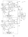
- Fig. 7 shows a circuit configuration example of a reference voltage generation circuit 70.
- the reference voltage generation circuit 70 two or more circuit configurations same as the circuit configuration in Fig. 1 (two in Fig. 7 ) are prepared, as a first reference voltage generation circuit 70a and a second reference voltage generation circuit 70b respectively.
- Each of the reference voltage generation circuits 70a and 70b includes reference feedback-type bias circuits 2a and 2b of the same circuit configuration as the feedback-type bias circuit 2 in Fig. 1 , reference load circuits 3a and 3b of the same circuit configuration as the load circuit 3 in Fig.
- reference precharge circuits 5a and 5b of the same circuit configuration as the precharge circuit 5 in Fig. 1 reference hold circuits 6a and 6b of the same circuit configuration of the hold circuit 6 in Fig. 1 , reference cells 7a and 7b of the same element structure as the memory cells in the memory array 7, and NMOSs 8a and 8b same as the bit line selection transistor 8, and is structured in the same manners as the circuit configuration shown in Fig. 1 .
- NMOSs 8a and 8b same as the bit line selection transistor 8
- the difference between the first reference voltage generation circuit 70a and the second reference voltage generation circuit 70b is that the threshold voltage of reference cell 7a is set to the higher threshold voltage of the memory cell, while the threshold voltage of the reference cell 7b is set to the lower threshold voltage of the memory cell. Therefore, the first reference voltage Vref1 that the first reference voltage generation circuit 70a generates becomes same as the voltage of the readout input node N1 in the case where the threshold voltage of the memory cell is high, in the readout circuit in Fig. 1 or 4 , and the second reference voltage Vref2 that the second reference voltage generation circuit 70b generates becomes same as the voltage of the readout input node N1 in the case where the threshold voltage of the memory cell is low, in the readout circuit in Fig. 1 or 4 , at a same timing respectively.
- an NMOS at each input stage of differential inputs is structured by a parallel circuit of two NMOSs, and to the gate of each NMOS of one differential input, the first reference voltage Vref1 and the second reference voltage Vref2 are input separately, and to the gate of each NMOS of the other differential input, the voltage of the readout input node N1 is input.
- the reference voltage side in order to make the gate capacity same as the memory cell (readout input node N1) side, a dummy MOSFET is added to the node of each reference voltage, or each reference voltage is used as to function as reference voltage input of other comparator circuit 4.
- a precharge signal generation circuit 80 which determines the active period (precharge period) of the precharge circuit 5 in the inventive circuit 1 will be described hereinafter.
- Fig. 8 shows circuit configuration example of the precharge signal generation circuit 80.
- the precharge signal generation circuit 80 includes a dummy bit line DBL whose parasitic capacity and parasitic resistance are same as those of the bit line BL connected to the memory array 7 in Fig. 1 , a dummy precharge circuit 5c which may charge the dummy bit line DBL by the same charge current as the precharge circuit 5 in Fig. 1 up to the same charge voltage, a dummy feedback-type bias circuit 2c of the same circuit configuration as the feedback-type bias circuit 2 in Fig.
- a dummy load circuit 3c which may charge a dummy readout input node DN1 connected to the dummy bit line DBL via the transfer gate 20c of the dummy feedback-type bias circuit 2c by the same charge current as the load circuit 3 in Fig. 1
- a logic circuit unit 81 which generates a precharge signal PRC from voltage changes of the dummy readout input node DN1.
- the dummy readout input node DN1 corresponds to the readout input node N1 in the inventive circuit 1 in Fig.
- the dummy load circuit 3c is different from the load circuit 3 in Fig. 1 in that GND voltage is input to the gate of a PMOS 31c at the power source voltage side, therefore, it is always in an ON state during the precharge of the inventive circuit 1, and along with the voltage increase of the dummy bit line DBL, the voltage of the dummy readout input node DN1 increases.
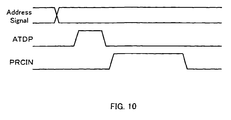
- Fig. 9 shows voltage waveforms of the control signal PRCIN which is input to the dummy precharge circuit 5c and the logic circuit unit 81, the precharge signal PRC that the precharge signal generation circuit 80 outputs, the dummy readout input node DN1, and the internal node N6 of the logic circuit unit 81.
- the control signal PRCIN is the signal which is generated by use of an inverter delay circuit or the like on the basis of the signal generated by an address transition detection circuit or the like, wherein the "H" level period is sufficiently longer than the precharge period.
- the rise in this control signal PRCIN the rise of the precharge signal PRC is determined, and the timing to determine the fall of the precharge signal PRC, i.e., the precharge period of the inventive circuit 1 is determined by voltage changes of the dummy readout input node DN1. Thereby, the necessary and sufficient precharge period of the inventive circuit 1 is secured by the precharge signal PRC, even when operation voltages and operation temperatures and the like change.
- Fig. 10 shows a timing relation of the control signal PRCIN, the signal generated by the address transition detection circuit, and the address signal which is input to a semiconductor device equipped with the inventive circuit 1.
- the timing shown in Fig. 10 shows a case where the control signal PRCIN rises in response to the fall of the address transition detection signal ATDP.
- an inverter delay circuit may be added to the logic circuit unit 81, or the length of the dummy bit line DBL may be made different from the length of the bit line BL to be connected to the memory array 7, and thereby the parasitic capacity and parasitic resistance of the dummy bit line DBL may be adjusted.
- Fig. 11 shows a circuit example of a feedback-type bias circuit 26 according to another embodiment.
- the feedback-type bias circuit 26 in Fig. 11 includes the same transfer gate 20 as the feedback-type bias circuit 2 in Fig. 1 , and a comparator circuit 27 which takes a reference voltage Vr and the voltage of the node N2 as inputs.
- the internal node N3 shifts to an "H" level when the voltage of the node N2 is lower than the reference voltage Vr, while it shifts to a "L" level when the voltage of the node N2 is higher.
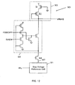
- Fig. 12 is a circuit configuration example of a bias voltage generation circuit 90.
- the bias voltage generation circuit 90 includes a reference feedback-type bias circuit 92 of the same circuit configuration as the feedback-type bias circuit 2 in Fig. 1 , a reference load circuit 93 formed by a series circuit of two PMOSs in the same manner as the load circuit 3 in Fig. 1 , an NMOS 94 of the same characteristic as the bit line selection transistor 8, and a bias voltage generation reference cell 91 of the same element structure as for example the memory cell in the memory array 7.
- the bias voltage VBIAS is a predetermined voltage which is determined by the currents of the reference load circuit 93 and the bias voltage generation reference cell 91, and becomes a gate input of the PMOS 32 of the load circuit 93.
- the bias voltage VBIAS may be freely adjusted by the threshold voltage of the bias voltage generation reference cell 91. Further, it may be freely adjusted by adjusting the current supply capacity of the reference load circuit 93, for example, the gate width or the gate length of the PMOSs 31 and 32. And, the internal node N7 of the bias voltage generation circuit 90 is an extremely short wire, different from the bit line BL which is connected to the memory cell in the memory array 7, and, as for the gate voltage to be input to the bias voltage generation reference cell 91, the voltage of the word line connected to the memory cell may be input. Because many memory cells do not connect to the internal node N7 though many memory cells do connect in the memory array 7, it is possible to change the gate voltage of the bias voltage generation reference cell 91 at a high speed.
- the reference feedback-type bias circuit 92 is for fixing the drain voltage (voltage of the node N7) of the bias voltage generation reference cell 91, if there is no influence of the fluctuation in the drain voltage upon the bias voltage VBIAS characteristic to be input to the gate of the PMOS 32 of the load circuit 3, the reference feedback-type bias circuit 92 is not necessarily arranged.
- Fig. 13 shows another circuit configuration of a bias voltage generation circuit.
- the circuit configuration shown in Fig. 13 is a structure for the case when the bias voltage VBIAS is supplied in common to plural load circuits 3 of the inventive circuit 1, the load capacity that the bias voltage VBIAS drives becomes large, and it takes time to fix a predetermined output voltage.
- the output VBIAS of the bias voltage generation circuit 90 in Fig. 12 is connected to the node VBIAS 1 of an amplification circuit 95, and the node VBIAS2 of the amplification circuit 95 is made as gate input of the PMOS 32 of the load circuit 2.
- the current which flow through the node N7 of the bias voltage generation circuit 90 is amplified by the amplification circuit 95, and the time until the output voltage of the node VBIAS2 becomes stable is shortened.
- gate input may be a control signal which becomes an "H" level for the period from the moment just before the charge completion timing of the bit line BL to the moment of completion of the precharge period.
- the inventive circuit 1 may be applied to a flash memory wherein memory cells in the memory array 7 are flash memories as in the embodiment, and besides flash memory array, it may be applied to cases where memory arrays are structured by memory elements which memorize data by the size of memory cell current.
- a semiconductor memory device equipped with a memory array comprising side wall type nonvolatile memory cells equipped with an electric charge hold area at the side of control gate (memory elements called side wall memories).
Landscapes
- Engineering & Computer Science (AREA)
- Power Engineering (AREA)
- Read Only Memory (AREA)
- Dram (AREA)
Applications Claiming Priority (2)
| Application Number | Priority Date | Filing Date | Title |
|---|---|---|---|
| JP2003433813 | 2003-12-26 | ||
| JP2003433813A JP2005190626A (ja) | 2003-12-26 | 2003-12-26 | 半導体読み出し回路 |
Publications (3)
| Publication Number | Publication Date |
|---|---|
| EP1548743A2 EP1548743A2 (en) | 2005-06-29 |
| EP1548743A3 EP1548743A3 (en) | 2005-11-09 |
| EP1548743B1 true EP1548743B1 (en) | 2012-04-11 |
Family
ID=34545087
Family Applications (1)
| Application Number | Title | Priority Date | Filing Date |
|---|---|---|---|
| EP04258043A Expired - Fee Related EP1548743B1 (en) | 2003-12-26 | 2004-12-22 | Semiconductor readout circuit |
Country Status (6)
| Country | Link |
|---|---|
| US (1) | US7027341B2 (zh) |
| EP (1) | EP1548743B1 (zh) |
| JP (1) | JP2005190626A (zh) |
| KR (1) | KR100582924B1 (zh) |
| CN (1) | CN100538901C (zh) |
| TW (1) | TWI258769B (zh) |
Families Citing this family (23)
| Publication number | Priority date | Publication date | Assignee | Title |
|---|---|---|---|---|
| DE102004047331B3 (de) * | 2004-09-29 | 2006-05-11 | Infineon Technologies Ag | Integrierter Halbleiterspeicher |
| US7769858B2 (en) * | 2005-02-23 | 2010-08-03 | International Business Machines Corporation | Method for efficiently hashing packet keys into a firewall connection table |
| FR2888659A1 (fr) * | 2005-07-18 | 2007-01-19 | St Microelectronics Sa | Amplificateur de lecture pour memoire non volatile |
| JP2008052876A (ja) * | 2006-08-28 | 2008-03-06 | Toshiba Corp | 半導体記憶装置 |
| JP2008090885A (ja) * | 2006-09-29 | 2008-04-17 | Oki Electric Ind Co Ltd | 半導体集積装置 |
| KR20100097891A (ko) | 2009-02-27 | 2010-09-06 | 삼성전자주식회사 | 비휘발성 메모리 장치 및 이를 위한 바이어스 생성 회로 |
| TWI409817B (zh) * | 2009-04-20 | 2013-09-21 | Winbond Electronics Corp | 快閃記憶體的資料感測模組與感測電路 |
| US8284610B2 (en) * | 2009-06-10 | 2012-10-09 | Winbond Electronics Corp. | Data sensing module and sensing circuit for flash memory |
| CN101930801B (zh) * | 2009-06-24 | 2013-10-23 | 华邦电子股份有限公司 | 快闪存储器的数据感测模块与感测电路 |
| US8130566B2 (en) * | 2010-02-25 | 2012-03-06 | Taiwan Semiconductor Manufacturing Company, Ltd. | Sense amplifier and method of sensing data using the same |
| JP5679801B2 (ja) * | 2010-12-22 | 2015-03-04 | ラピスセミコンダクタ株式会社 | 不揮発性記憶装置 |
| US8693272B2 (en) * | 2011-06-30 | 2014-04-08 | Qualcomm Incorporated | Sensing circuit |
| US8531902B2 (en) * | 2011-06-30 | 2013-09-10 | Qualcomm Incorporated | Sensing circuit |
| US9042187B2 (en) * | 2012-09-17 | 2015-05-26 | Intel Corporation | Using a reference bit line in a memory |
| US9378814B2 (en) * | 2013-05-21 | 2016-06-28 | Sandisk Technologies Inc. | Sense amplifier local feedback to control bit line voltage |
| KR20160041329A (ko) * | 2014-10-07 | 2016-04-18 | 에스케이하이닉스 주식회사 | 반도체 장치 |
| US9478308B1 (en) * | 2015-05-26 | 2016-10-25 | Intel IP Corporation | Programmable memory device sense amplifier |
| JP6674616B2 (ja) * | 2015-06-10 | 2020-04-01 | パナソニック株式会社 | 半導体装置、半導体装置の読み出し方法、及び半導体装置を搭載したicカード |
| KR20170045445A (ko) | 2015-10-16 | 2017-04-27 | 삼성전자주식회사 | 충전 노드를 충전하는 구동 회로 |
| CN107464580B (zh) * | 2016-06-03 | 2020-06-05 | 中芯国际集成电路制造(上海)有限公司 | 高速预充电敏感放大器电路、快速读取电路及电子装置 |
| CN107331413B (zh) * | 2017-06-30 | 2020-02-21 | 上海芯火半导体有限公司 | 一种反馈型防过充电流敏感放大器及其控制方法 |
| CN108389598B (zh) * | 2018-03-26 | 2020-09-29 | 上海华虹宏力半导体制造有限公司 | 反相器钳位的灵敏放大器电路 |
| CN113409841B (zh) * | 2021-06-30 | 2023-08-04 | 芯天下技术股份有限公司 | 一种基准电流产生电路、方法、电子设备及测试工装 |
Family Cites Families (7)
| Publication number | Priority date | Publication date | Assignee | Title |
|---|---|---|---|---|
| FR2714202B1 (fr) * | 1993-12-22 | 1996-01-12 | Sgs Thomson Microelectronics | Mémoire en circuit intégré à temps de lecture amélioré. |
| JP3404127B2 (ja) | 1994-06-17 | 2003-05-06 | 富士通株式会社 | 半導体記憶装置 |
| JPH08148580A (ja) * | 1994-08-01 | 1996-06-07 | Seiko Instr Inc | 半導体集積回路装置 |
| JP3116921B2 (ja) * | 1998-09-22 | 2000-12-11 | 日本電気株式会社 | 半導体記憶装置 |
| JP3471251B2 (ja) | 1999-04-26 | 2003-12-02 | Necエレクトロニクス株式会社 | 不揮発性半導体記憶装置 |
| JP2001160294A (ja) * | 1999-11-30 | 2001-06-12 | Sharp Corp | 半導体記憶装置 |
| JP4052895B2 (ja) * | 2002-08-07 | 2008-02-27 | シャープ株式会社 | メモリセル情報の読み出し回路および半導体記憶装置 |
-
2003
- 2003-12-26 JP JP2003433813A patent/JP2005190626A/ja active Pending
-
2004
- 2004-12-21 TW TW093139887A patent/TWI258769B/zh not_active IP Right Cessation
- 2004-12-22 US US11/022,401 patent/US7027341B2/en not_active Expired - Fee Related
- 2004-12-22 EP EP04258043A patent/EP1548743B1/en not_active Expired - Fee Related
- 2004-12-24 KR KR1020040111928A patent/KR100582924B1/ko not_active IP Right Cessation
- 2004-12-27 CN CNB2004100615271A patent/CN100538901C/zh not_active Expired - Fee Related
Also Published As
| Publication number | Publication date |
|---|---|
| CN100538901C (zh) | 2009-09-09 |
| KR20050067061A (ko) | 2005-06-30 |
| TW200527436A (en) | 2005-08-16 |
| US20050162953A1 (en) | 2005-07-28 |
| EP1548743A3 (en) | 2005-11-09 |
| EP1548743A2 (en) | 2005-06-29 |
| US7027341B2 (en) | 2006-04-11 |
| TWI258769B (en) | 2006-07-21 |
| JP2005190626A (ja) | 2005-07-14 |
| KR100582924B1 (ko) | 2006-05-25 |
| CN1637951A (zh) | 2005-07-13 |
Similar Documents
| Publication | Publication Date | Title |
|---|---|---|
| EP1548743B1 (en) | Semiconductor readout circuit | |
| JP4078083B2 (ja) | フラッシュメモリ装置の感知増幅回路 | |
| KR100562375B1 (ko) | 판독회로 및 이를 포함한 반도체 메모리 장치 | |
| KR100541816B1 (ko) | 반도체 메모리에서의 데이터 리드 회로 및 데이터 리드 방법 | |
| US6438038B2 (en) | Read circuit of nonvolatile semiconductor memory | |
| JP4738347B2 (ja) | 半導体装置及び半導体装置の制御方法 | |
| JP4303004B2 (ja) | 低電圧不揮発性半導体メモリ装置 | |
| JP4922932B2 (ja) | 半導体装置およびその制御方法 | |
| JP3706135B2 (ja) | 不揮発性半導体メモリのためのセンス増幅器 | |
| KR20010070012A (ko) | 비휘발성 반도체 기억 장치 | |
| US6879521B2 (en) | Threshold voltage adjustment method of non-volatile semiconductor memory device and non-volatile semiconductor memory device | |
| JP3299910B2 (ja) | 半導体記憶装置およびその読み出し方法 | |
| KR100929304B1 (ko) | 온도 보상 상 변화 메모리 장치 | |
| KR100944322B1 (ko) | 상 변화 메모리 장치 | |
| WO2006001058A1 (ja) | 半導体装置及びソース電圧制御方法 | |
| US20080080256A1 (en) | Delay circuit for controlling a pre-charging time of bit lines of a memory cell array | |
| US7538584B2 (en) | Sense amplifier | |
| US6188612B1 (en) | Semiconductor memory | |
| KR20140080943A (ko) | 비휘발성 메모리 장치 | |
| JP2013020661A (ja) | 半導体記憶装置 | |
| JP2009134792A (ja) | 半導体記憶装置 |
Legal Events
| Date | Code | Title | Description |
|---|---|---|---|
| PUAI | Public reference made under article 153(3) epc to a published international application that has entered the european phase |
Free format text: ORIGINAL CODE: 0009012 |
|
| AK | Designated contracting states |
Kind code of ref document: A2 Designated state(s): AT BE BG CH CY CZ DE DK EE ES FI FR GB GR HU IE IS IT LI LT LU MC NL PL PT RO SE SI SK TR |
|
| AX | Request for extension of the european patent |
Extension state: AL BA HR LV MK YU |
|
| PUAL | Search report despatched |
Free format text: ORIGINAL CODE: 0009013 |
|
| AK | Designated contracting states |
Kind code of ref document: A3 Designated state(s): AT BE BG CH CY CZ DE DK EE ES FI FR GB GR HU IE IS IT LI LT LU MC NL PL PT RO SE SI SK TR |
|
| AX | Request for extension of the european patent |
Extension state: AL BA HR LV MK YU |
|
| RIC1 | Information provided on ipc code assigned before grant |
Ipc: 7G 11C 7/12 A Ipc: 7G 11C 16/26 B Ipc: 7G 11C 16/24 B |
|
| 17P | Request for examination filed |
Effective date: 20060123 |
|
| AKX | Designation fees paid |
Designated state(s): DE FR GB IT |
|
| 17Q | First examination report despatched |
Effective date: 20071213 |
|
| REG | Reference to a national code |
Ref country code: DE Ref legal event code: R079 Ref document number: 602004037266 Country of ref document: DE Free format text: PREVIOUS MAIN CLASS: G11C0007120000 Ipc: G11C0007060000 |
|
| RIC1 | Information provided on ipc code assigned before grant |
Ipc: G11C 7/06 20060101AFI20110829BHEP Ipc: G11C 16/24 20060101ALI20110829BHEP Ipc: G11C 7/12 20060101ALI20110829BHEP Ipc: G11C 16/26 20060101ALI20110829BHEP |
|
| GRAJ | Information related to disapproval of communication of intention to grant by the applicant or resumption of examination proceedings by the epo deleted |
Free format text: ORIGINAL CODE: EPIDOSDIGR1 |
|
| GRAP | Despatch of communication of intention to grant a patent |
Free format text: ORIGINAL CODE: EPIDOSNIGR1 |
|
| GRAS | Grant fee paid |
Free format text: ORIGINAL CODE: EPIDOSNIGR3 |
|
| GRAA | (expected) grant |
Free format text: ORIGINAL CODE: 0009210 |
|
| AK | Designated contracting states |
Kind code of ref document: B1 Designated state(s): DE FR GB IT |
|
| REG | Reference to a national code |
Ref country code: GB Ref legal event code: FG4D |
|
| REG | Reference to a national code |
Ref country code: DE Ref legal event code: R096 Ref document number: 602004037266 Country of ref document: DE Effective date: 20120606 |
|
| PLBE | No opposition filed within time limit |
Free format text: ORIGINAL CODE: 0009261 |
|
| STAA | Information on the status of an ep patent application or granted ep patent |
Free format text: STATUS: NO OPPOSITION FILED WITHIN TIME LIMIT |
|
| 26N | No opposition filed |
Effective date: 20130114 |
|
| REG | Reference to a national code |
Ref country code: DE Ref legal event code: R097 Ref document number: 602004037266 Country of ref document: DE Effective date: 20130114 |
|
| PGFP | Annual fee paid to national office [announced via postgrant information from national office to epo] |
Ref country code: DE Payment date: 20131218 Year of fee payment: 10 Ref country code: GB Payment date: 20131218 Year of fee payment: 10 |
|
| PGFP | Annual fee paid to national office [announced via postgrant information from national office to epo] |
Ref country code: IT Payment date: 20131206 Year of fee payment: 10 Ref country code: FR Payment date: 20131209 Year of fee payment: 10 |
|
| REG | Reference to a national code |
Ref country code: DE Ref legal event code: R119 Ref document number: 602004037266 Country of ref document: DE |
|
| GBPC | Gb: european patent ceased through non-payment of renewal fee |
Effective date: 20141222 |
|
| REG | Reference to a national code |
Ref country code: FR Ref legal event code: ST Effective date: 20150831 |
|
| PG25 | Lapsed in a contracting state [announced via postgrant information from national office to epo] |
Ref country code: DE Free format text: LAPSE BECAUSE OF NON-PAYMENT OF DUE FEES Effective date: 20150701 Ref country code: GB Free format text: LAPSE BECAUSE OF NON-PAYMENT OF DUE FEES Effective date: 20141222 |
|
| PG25 | Lapsed in a contracting state [announced via postgrant information from national office to epo] |
Ref country code: FR Free format text: LAPSE BECAUSE OF NON-PAYMENT OF DUE FEES Effective date: 20141231 |
|
| PG25 | Lapsed in a contracting state [announced via postgrant information from national office to epo] |
Ref country code: IT Free format text: LAPSE BECAUSE OF NON-PAYMENT OF DUE FEES Effective date: 20141222 |