EP1538560B1 - Antenne für Funkfrequenz-Identifikation - Google Patents
Antenne für Funkfrequenz-Identifikation Download PDFInfo
- Publication number
- EP1538560B1 EP1538560B1 EP04026191A EP04026191A EP1538560B1 EP 1538560 B1 EP1538560 B1 EP 1538560B1 EP 04026191 A EP04026191 A EP 04026191A EP 04026191 A EP04026191 A EP 04026191A EP 1538560 B1 EP1538560 B1 EP 1538560B1
- Authority
- EP
- European Patent Office
- Prior art keywords
- antenna
- slit
- rfid
- base film
- length
- Prior art date
- Legal status (The legal status is an assumption and is not a legal conclusion. Google has not performed a legal analysis and makes no representation as to the accuracy of the status listed.)
- Expired - Lifetime
Links
Images


Classifications
-
- H—ELECTRICITY
- H01—ELECTRIC ELEMENTS
- H01Q—ANTENNAS, i.e. RADIO AERIALS
- H01Q1/00—Details of, or arrangements associated with, antennas
- H01Q1/36—Structural form of radiating elements, e.g. cone, spiral, umbrella; Particular materials used therewith
- H01Q1/38—Structural form of radiating elements, e.g. cone, spiral, umbrella; Particular materials used therewith formed by a conductive layer on an insulating support
-
- G—PHYSICS
- G06—COMPUTING OR CALCULATING; COUNTING
- G06K—GRAPHICAL DATA READING; PRESENTATION OF DATA; RECORD CARRIERS; HANDLING RECORD CARRIERS
- G06K19/00—Record carriers for use with machines and with at least a part designed to carry digital markings
- G06K19/06—Record carriers for use with machines and with at least a part designed to carry digital markings characterised by the kind of the digital marking, e.g. shape, nature, code
- G06K19/067—Record carriers with conductive marks, printed circuits or semiconductor circuit elements, e.g. credit or identity cards also with resonating or responding marks without active components
- G06K19/07—Record carriers with conductive marks, printed circuits or semiconductor circuit elements, e.g. credit or identity cards also with resonating or responding marks without active components with integrated circuit chips
- G06K19/077—Constructional details, e.g. mounting of circuits in the carrier
- G06K19/07749—Constructional details, e.g. mounting of circuits in the carrier the record carrier being capable of non-contact communication, e.g. constructional details of the antenna of a non-contact smart card
- G06K19/07773—Antenna details
- G06K19/07777—Antenna details the antenna being of the inductive type
- G06K19/07779—Antenna details the antenna being of the inductive type the inductive antenna being a coil
- G06K19/07783—Antenna details the antenna being of the inductive type the inductive antenna being a coil the coil being planar
-
- G—PHYSICS
- G06—COMPUTING OR CALCULATING; COUNTING
- G06K—GRAPHICAL DATA READING; PRESENTATION OF DATA; RECORD CARRIERS; HANDLING RECORD CARRIERS
- G06K19/00—Record carriers for use with machines and with at least a part designed to carry digital markings
- G06K19/06—Record carriers for use with machines and with at least a part designed to carry digital markings characterised by the kind of the digital marking, e.g. shape, nature, code
- G06K19/067—Record carriers with conductive marks, printed circuits or semiconductor circuit elements, e.g. credit or identity cards also with resonating or responding marks without active components
- G06K19/07—Record carriers with conductive marks, printed circuits or semiconductor circuit elements, e.g. credit or identity cards also with resonating or responding marks without active components with integrated circuit chips
- G06K19/077—Constructional details, e.g. mounting of circuits in the carrier
- G06K19/07749—Constructional details, e.g. mounting of circuits in the carrier the record carrier being capable of non-contact communication, e.g. constructional details of the antenna of a non-contact smart card
- G06K19/07773—Antenna details
- G06K19/07786—Antenna details the antenna being of the HF type, such as a dipole
-
- H—ELECTRICITY
- H01—ELECTRIC ELEMENTS
- H01Q—ANTENNAS, i.e. RADIO AERIALS
- H01Q1/00—Details of, or arrangements associated with, antennas
- H01Q1/12—Supports; Mounting means
- H01Q1/22—Supports; Mounting means by structural association with other equipment or articles
-
- H—ELECTRICITY
- H01—ELECTRIC ELEMENTS
- H01Q—ANTENNAS, i.e. RADIO AERIALS
- H01Q23/00—Antennas with active circuits or circuit elements integrated within them or attached to them
-
- H—ELECTRICITY
- H01—ELECTRIC ELEMENTS
- H01Q—ANTENNAS, i.e. RADIO AERIALS
- H01Q7/00—Loop antennas with a substantially uniform current distribution around the loop and having a directional radiation pattern in a plane perpendicular to the plane of the loop
-
- H—ELECTRICITY
- H10—SEMICONDUCTOR DEVICES; ELECTRIC SOLID-STATE DEVICES NOT OTHERWISE PROVIDED FOR
- H10W—GENERIC PACKAGES, INTERCONNECTIONS, CONNECTORS OR OTHER CONSTRUCTIONAL DETAILS OF DEVICES COVERED BY CLASS H10
- H10W72/00—Interconnections or connectors in packages
- H10W72/071—Connecting or disconnecting
- H10W72/072—Connecting or disconnecting of bump connectors
- H10W72/07251—Connecting or disconnecting of bump connectors characterised by changes in properties of the bump connectors during connecting
-
- H—ELECTRICITY
- H10—SEMICONDUCTOR DEVICES; ELECTRIC SOLID-STATE DEVICES NOT OTHERWISE PROVIDED FOR
- H10W—GENERIC PACKAGES, INTERCONNECTIONS, CONNECTORS OR OTHER CONSTRUCTIONAL DETAILS OF DEVICES COVERED BY CLASS H10
- H10W72/00—Interconnections or connectors in packages
- H10W72/20—Bump connectors, e.g. solder bumps or copper pillars; Dummy bumps; Thermal bumps
Definitions
- EP 1 0055 943 a2 describes a microstrip patch designed as a resonant antenna.
- a demerit resulting from a situation where no resonance is obtained due to a reduction in size of an antenna to less than a half-wavelength is compensated for by matching the impedance of the circuit (which is typically a semiconductor integrated circuit) of RFID to that of the antenna.
- the antenna 101 is connected to the rectifier circuit 302.
- the high-frequency current flowing through the antenna 101 is rectified by the rectifier circuit 302 and then is inputted into the clock extracting circuit 303.
- the clock extracting circuit 303 a clock width and a clock interval are extracted from a high-frequency carrier with precision.
- An extracted low-frequency clock pulse is inputted into the counter/memory circuit 305, which then performs processing such as certification of the RFID.
- the input impedance of the rectifier circuit 302 is determined by the value of its internal load, in other words, the scheme adopted by the rectifier circuit 302, the shape of rectifiers, the parasitic effect of the rectifier circuit, and the like.
- its parasitic capacitance is a significant impedance factor. Therefore, when the matching between the antenna 101 and the rectifier circuit 302 is insufficient, the energy from the antenna 101 is not sufficiently supplied to the rectifier circuit 302.
- an antenna line is required to be dealt with as a distributed constant circuit. It is also required that the antenna 101 functions not only as a resonant circuit but also as a matching circuit for the high-frequency current to the RFID chip.
- the matching means a situation where the high-frequency current is inputted from the antenna 101 to the RFID chip 103 without being reflected in a transition portion to a different system (connection points between the antenna 101 and the RFID chip 103).
- FIG. 3 is a block diagram showing the principle of operation of the antenna for the RFID according to the embodiment of this invention and shows the equivalent circuit of the slit 102 when the antenna 101 is connected to the RFID chip 103.
- the slit 102 constitutes the distributed constant circuit, an inductance L exists along a slit length, and a capacitance C exists inversely proportional to a slit width.
- the characteristic impedance of the distributed constant circuit is expressed by a square root found by dividing the inductance L by the capacitance C. Consequently, the slit length is in an approximately proportional relation with the inductance L and when the slit length is lengthen, the inductance L is increased.
- the slit width is in an approximately inversely proportional relation with the capacitance C and when the slit width is widened, the capacitance C is decreased.
- the antenna in the shape according to the first embodiment of this invention, it is possible to produce a RFID chip where the antenna is miniaturized and a practical communication distance is secured while managing a reduction in communication distance due to the miniaturization.
- miniaturization of the antenna also makes it possible to miniaturize the RFID provided with the antenna, which widens the range of objects to which the RFID can be attached. For instance, the RFID can be attached to the lid portion of a small medicine bottle or the like.
- the slit length can be shortened to make it further possible to miniaturize the antenna. Also, in the modification shown in FIG. 7, with the slit width 602 partially enlarged, it is possible to further shorten the slit length to miniaturize the antenna.
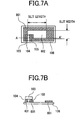
- the RFID according to the fourth embodiment is characterized in that a RFID chip 804 with electrodes provided on both surfaces thereof is used. It should be noted that each construction element that functions in the same manner as in the first through third embodiments described above is given the same reference numeral and the detailed description thereof will be omitted.
- the antenna for the RFID according to the fifth embodiment is characterized in that a slit is provided in a slanting direction. It should be noted that each construction element that functions in the same manner as in the first through fourth embodiments described above is given the same reference numeral and the detailed description thereof will be omitted.
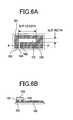
- the conductive cover metal 903 is provided on a lower surface of the cover film 904.
- a layer of anisotropic conductive adhesives 905 is provided between the base film 906 and the cover film 904 (between the antenna 910 through 911 and the cover metal 903).
- the anisotropic conductive adhesives 905 do not have conductivity under an ordinary state but exhibits conductivity through application of a pressure in a direction in which the pressure is applied. Consequently, by applying a pressure at a short point 909 provided on an antenna 911 side on the base film 906 (applying a pressure from a cover film 904 side as shown in FIG. 10, for instance), electrical continuity is established between the antenna 911 of the base film 906 and the cover metal 903 of the cover film 904.
- removing the corner portions of the antenna without exerting any influences on the performance of the antenna makes it possible to miniaturize the antenna so as to realize RFID that can be attached in a narrow and small space.
- the antenna for the RFID according to the seventh embodiment is characterized in that it has a quadrangular shaped. It should be noted that each construction element that functions in the same manner as in the first through sixth embodiments described above is given the same reference numeral and the detailed description thereof will be omitted.
- the antenna for the RFID according to the eighth embodiment is characterized in that it has a circular shape. It should be noted that each construction element that functions in the same manner as in the first through seventh embodiments described above is given the same reference numeral and the detailed description thereof will be omitted.
- setting the slit length and the slit width approximately equal to each other makes it possible to miniaturize the antenna without exerting any influences on the performance of the antenna so as to realize RFID that can be attached in a narrow and small space.
- FIG. 15 is a perspective view of an embodiment where the RFID according to the embodiments of this invention is affixed to a receiving container (e.g. bottle).
- a receiving container e.g. bottle
Landscapes
- Engineering & Computer Science (AREA)
- Computer Hardware Design (AREA)
- Microelectronics & Electronic Packaging (AREA)
- Physics & Mathematics (AREA)
- General Physics & Mathematics (AREA)
- Theoretical Computer Science (AREA)
- Computer Networks & Wireless Communication (AREA)
- Details Of Aerials (AREA)
- Support Of Aerials (AREA)
- Credit Cards Or The Like (AREA)
- Details Of Rigid Or Semi-Rigid Containers (AREA)
- Waveguide Aerials (AREA)
Claims (12)
- Nicht-resonante Antenne, die zum Betrieb bei im wesentlichen 2,45 GHz ausgelegt und an einen IC-Chip (103) zur drahtlosen Identifikation angeschlossen ist, wobei die Antenne (101, 501, 601, 801, 910) einen Leiter mit einer Öffnung (102) und zwei durch die Öffnung (102) getrennten Anschlußpunkten (104, 105) aufweist, dadurch gekennzeichnet, daß
die Länge der Öffnung (102) zwischen 2,4 mm und 3,0 mm beträgt,
die Breite der Öffnung (102) zwischen 1,0 mm und 1,4 mm beträgt, und
die Fläche der Öffnung (102) zwischen 3,0 mm2 und 4,2 mm2 beträgt. - Antenne nach Anspruch 1, wobei die Länge der Öffnung (102) im wesentlichen 3 mm beträgt.
- Nicht-resonante Antenne, die zum Betrieb bei im wesentlichen 2,45 GHz ausgelegt und an einen IC-Chip (103) zur drahtlosen Identifikation angeschlossen ist, wobei die Antenne (1201, 1301) einen Leiter mit einer Öffnung (102) und zwei durch die Öffnung (102) getrennten Anschlußpunkten (104, 105) aufweist,
dadurch gekennzeichnet, daß die Länge und die Breite der Öffnung (102) im wesentlichen gleich sind und beide zwischen 2,0 mm und 2,4 mm betragen. - Antenne nach Anspruch 1 oder 2, wobei
die Frequenz einer auf die Antenne (101) ausgesendeten Funkwelle im wesentlichen 2,45 GHz beträgt, und
die Eingangsimpedanz des IC-Chips (103) im wesentlichen 60 Ω beträgt. - Antenne nach Anspruch 1, die zwischen einem Basisfilm (906) und einem Deckfilm (904) gebildet ist, wobei
der Deckfilm (904) mit einem elektrischen Leiter auf wenigstens einem Teil des Basisfilms (906) aufgebracht ist,
die auf dem Basisfilm (906) gebildete Antenne (910) und der elektrische Leiter des Deckfilms (904) an einem Kurzkontaktpunkt (909) verbunden sind, und
der IC-Chip (804) zwischen dem Basisfilm (906) und dem Deckfilm (904) angeordnet und mit diesen beiden verbunden ist. - Antenne nach Anspruch 5, wobei die auf dem Basisfilm (906) gebildete Antenne (910) und der elektrische Leiter des Deckfilms (904) an dem Kurzkontaktpunkt durch die anisotropen leitfähigen Klebemittel (905) angeschlossen sind, die zwischen dem Basisfilm (906) und dem Deckfilm (904) angebracht sind.
- Antenne nach Anspruch 1, wobei
die Antenne (801) einen gefalteten Verlaufsabschnitt (803) aufweist,
der gefaltete Abschnitt (803) zu einer Position gefaltet ist, die die Antenne (801) überlappt,
der IC-Chip (804) Anschlüsse zur Verbindung auf seinen beiden Oberflächen aufweist, und
die Antenne (801) und der gefaltete Abschnitt (803) an den IC-Chip (804) angeschlossen sind. - Antenne nach Anspruch 1, die auf einem Basisfilm (701) mit hoher Dielektrizitätskonstante gebildet ist und die durch eine Decklage (702) mit hoher Dielektrizitätskonstante abgedeckt ist.
- Antenne nach Anspruch 1, die eine rechteckige Form aufweist, wobei Eckabschnitte (1001) der Antenne (601) in einer schräg verlaufenden Richtung entfernt sind.
- Funkfrequenz-Identifiziereinrichtung mit der Antenne (101) nach einem der vorstehenden Ansprüche.
- Behälter zum Aufnehmen eines Pulvers oder einer Flüssigkeit, der die Funkfrequenz-Identifiziereinrichtung gemäß Anspruch 10 aufweist, wobei die Funkfrequenz-Identifiziereinrichtung auf einem Hauptkörperabschnitt (1104) oder einem Deckelabschnitt (1103) des Behälters angebracht ist.
- Antenne nach Anspruch 1, ferner mit einem Basisfilm (106), wobei der Leiter auf dem Basisfilm (106) gebildet ist, und der Basisfilm (106) vorzugsweise aus einem Material mit hoher Dielektrizitätskonstante hergestellt ist.
Applications Claiming Priority (2)
| Application Number | Priority Date | Filing Date | Title |
|---|---|---|---|
| JP2003406031 | 2003-12-04 | ||
| JP2003406031A JP4177241B2 (ja) | 2003-12-04 | 2003-12-04 | 無線icタグ用アンテナ、無線icタグ及び無線icタグ付き容器 |
Publications (3)
| Publication Number | Publication Date |
|---|---|
| EP1538560A2 EP1538560A2 (de) | 2005-06-08 |
| EP1538560A3 EP1538560A3 (de) | 2005-07-06 |
| EP1538560B1 true EP1538560B1 (de) | 2007-01-24 |
Family
ID=34463996
Family Applications (1)
| Application Number | Title | Priority Date | Filing Date |
|---|---|---|---|
| EP04026191A Expired - Lifetime EP1538560B1 (de) | 2003-12-04 | 2004-11-04 | Antenne für Funkfrequenz-Identifikation |
Country Status (4)
| Country | Link |
|---|---|
| US (1) | US7256739B2 (de) |
| EP (1) | EP1538560B1 (de) |
| JP (1) | JP4177241B2 (de) |
| DE (1) | DE602004004482T2 (de) |
Cited By (1)
| Publication number | Priority date | Publication date | Assignee | Title |
|---|---|---|---|---|
| EP2175519A1 (de) * | 2008-10-09 | 2010-04-14 | Hitachi Ltd. | Hochfrequenz-IC-Etikett |
Families Citing this family (151)
| Publication number | Priority date | Publication date | Assignee | Title |
|---|---|---|---|---|
| JP3803085B2 (ja) * | 2002-08-08 | 2006-08-02 | 株式会社日立製作所 | 無線icタグ |
| EP1830309A4 (de) * | 2003-12-05 | 2009-05-13 | Hitachi Chemical Co Ltd | Verfahren zur herstellung von elektronischen einrichtungen |
| US7528728B2 (en) * | 2004-03-29 | 2009-05-05 | Impinj Inc. | Circuits for RFID tags with multiple non-independently driven RF ports |
| USD562810S1 (en) | 2004-03-29 | 2008-02-26 | Impinj, Inc. | Radio frequency identification tag antenna assembly |
| US7667589B2 (en) * | 2004-03-29 | 2010-02-23 | Impinj, Inc. | RFID tag uncoupling one of its antenna ports and methods |
| USD587691S1 (en) | 2004-03-29 | 2009-03-03 | Impinj, Inc. | Radio frequency identification tag antenna assembly |
| US7423539B2 (en) | 2004-03-31 | 2008-09-09 | Impinj, Inc. | RFID tags combining signals received from multiple RF ports |
| KR100603761B1 (ko) * | 2004-04-22 | 2006-07-24 | 삼성전자주식회사 | 마이크로웨이브 트랜스폰더 |
| USD544469S1 (en) * | 2004-07-15 | 2007-06-12 | Nippon Sheet Glass Company, Limited | Planar antenna element for vehicle window pane |
| USD549696S1 (en) * | 2004-07-15 | 2007-08-28 | Nippon Sheet Glass Company, Limited | Planar antenna element for vehicle windowpane |
| US20060125605A1 (en) * | 2004-12-13 | 2006-06-15 | Atmel Germany Gmbh | Method for locating a backscatter-based transponder |
| KR100952797B1 (ko) * | 2004-12-14 | 2010-04-14 | 후지쯔 가부시끼가이샤 | 안테나 및 비접촉형 태그 |
| USD586336S1 (en) | 2004-12-30 | 2009-02-10 | Impinj, Inc. | Radio frequency identification tag antenna assembly |
| US8120492B2 (en) * | 2005-02-25 | 2012-02-21 | Tom Ahlkvist Scharfeld | Blister package with integrated electronic tag and method of manufacture |
| JP2006311372A (ja) * | 2005-04-28 | 2006-11-09 | Hitachi Ltd | 無線icタグ |
| JP4500214B2 (ja) * | 2005-05-30 | 2010-07-14 | 株式会社日立製作所 | 無線icタグ、及び無線icタグの製造方法 |
| JP4815891B2 (ja) * | 2005-06-22 | 2011-11-16 | 株式会社日立製作所 | 無線icタグ及びアンテナの製造方法 |
| EP1907991B1 (de) | 2005-06-25 | 2012-03-14 | Omni-ID Limited | Entkoppler für elektromagnetische strahlung |
| WO2007013152A1 (ja) * | 2005-07-27 | 2007-02-01 | Hitachi, Ltd. | 無線icタグ用リーダ |
| JP4787572B2 (ja) | 2005-08-25 | 2011-10-05 | 株式会社日立製作所 | 無線icタグ、及び無線icタグの製造方法 |
| US7598867B2 (en) * | 2005-09-01 | 2009-10-06 | Alien Technology Corporation | Techniques for folded tag antennas |
| JP4725261B2 (ja) * | 2005-09-12 | 2011-07-13 | オムロン株式会社 | Rfidタグの検査方法 |
| TWI269483B (en) * | 2005-09-23 | 2006-12-21 | Ind Tech Res Inst | Small size ultra-wideband antenna |
| JP4528239B2 (ja) * | 2005-10-03 | 2010-08-18 | 株式会社日立製作所 | 無線icタグ |
| US7646305B2 (en) * | 2005-10-25 | 2010-01-12 | Checkpoint Systems, Inc. | Capacitor strap |
| JP2007150868A (ja) * | 2005-11-29 | 2007-06-14 | Renesas Technology Corp | 電子装置およびその製造方法 |
| JP4871579B2 (ja) * | 2005-12-01 | 2012-02-08 | 東芝テック株式会社 | 無線タグ調整システム |
| JP4560480B2 (ja) * | 2005-12-13 | 2010-10-13 | Necトーキン株式会社 | 無線タグ |
| US7519328B2 (en) | 2006-01-19 | 2009-04-14 | Murata Manufacturing Co., Ltd. | Wireless IC device and component for wireless IC device |
| USD548225S1 (en) * | 2006-02-17 | 2007-08-07 | Impinj, Inc. | Radio frequency identification tag antenna assembly |
| USD546819S1 (en) * | 2006-02-17 | 2007-07-17 | Impinj, Inc. | Radio frequency identification tag antenna assembly |
| KR100968347B1 (ko) | 2006-04-14 | 2010-07-08 | 가부시키가이샤 무라타 세이사쿠쇼 | 안테나 |
| US9064198B2 (en) | 2006-04-26 | 2015-06-23 | Murata Manufacturing Co., Ltd. | Electromagnetic-coupling-module-attached article |
| FR2901041B1 (fr) * | 2006-05-12 | 2008-10-10 | Eric Heurtier | Etiquette integrant une antenne anti-vol rf et un transporteur rfid uhf |
| JP4681506B2 (ja) * | 2006-05-30 | 2011-05-11 | 株式会社日立製作所 | Icタグ |
| CN101467209B (zh) | 2006-06-30 | 2012-03-21 | 株式会社村田制作所 | 光盘 |
| JP4560017B2 (ja) * | 2006-08-03 | 2010-10-13 | 株式会社日立製作所 | ディスクメディアおよびディスクメディアの製造方法 |
| US7561107B2 (en) | 2006-09-07 | 2009-07-14 | Intelleflex Corporation | RFID device with microstrip antennas |
| USD543976S1 (en) * | 2006-09-21 | 2007-06-05 | Impinj, Inc. | RFID antenna |
| USD547306S1 (en) * | 2006-09-21 | 2007-07-24 | Impinj, Inc. | RFID antenna |
| JP4787705B2 (ja) * | 2006-09-21 | 2011-10-05 | 株式会社日立製作所 | 環状スロットアンテナ付きディスクメディアおよびその製造方法 |
| DE112007002024B4 (de) | 2006-09-26 | 2010-06-10 | Murata Mfg. Co., Ltd., Nagaokakyo-shi | Induktiv gekoppeltes Modul und Element mit induktiv gekoppeltem Modul |
| JP2008092198A (ja) * | 2006-09-29 | 2008-04-17 | Renesas Technology Corp | Rfidラベルタグおよびその製造方法 |
| WO2008044557A1 (fr) * | 2006-10-06 | 2008-04-17 | Yagi Antenna Inc. | Antenne avec plaque réfléchissante et sa structure de corps |
| JP5027481B2 (ja) * | 2006-11-06 | 2012-09-19 | 株式会社日立製作所 | Icタグ |
| JP4950627B2 (ja) | 2006-11-10 | 2012-06-13 | 株式会社日立製作所 | Rficタグとその使用方法 |
| DE102006061798A1 (de) * | 2006-12-21 | 2008-06-26 | Simons, Gisela | Verfahren zur Anbringung von Kennzeichen auf Substratoberflächen mit Hilfe eines Transferverfahrens |
| DE102006062308A1 (de) | 2006-12-27 | 2008-07-17 | ASTRA Gesellschaft für Asset Management mbH & Co. KG | Passives Detektierplättchen |
| WO2008096576A1 (ja) | 2007-02-06 | 2008-08-14 | Murata Manufacturing Co., Ltd. | 電磁結合モジュール付き包装材 |
| ATE555453T1 (de) | 2007-04-06 | 2012-05-15 | Murata Manufacturing Co | Funk-ic-vorrichtung |
| WO2008126649A1 (ja) | 2007-04-09 | 2008-10-23 | Murata Manufacturing Co., Ltd. | 無線icデバイス |
| JP4839257B2 (ja) * | 2007-04-11 | 2011-12-21 | 株式会社日立製作所 | Rfidタグ |
| US8235299B2 (en) | 2007-07-04 | 2012-08-07 | Murata Manufacturing Co., Ltd. | Wireless IC device and component for wireless IC device |
| KR101518521B1 (ko) * | 2007-04-18 | 2015-05-07 | 쓰리엠 이노베이티브 프로퍼티즈 캄파니 | 전기 전도성 표지판에 결합된 무선 주파수 식별 기능 |
| EP2138962B1 (de) | 2007-04-26 | 2012-01-04 | Murata Manufacturing Co. Ltd. | Drahtlose ic-vorrichtung |
| EP2141769A4 (de) | 2007-04-27 | 2010-08-11 | Murata Manufacturing Co | Drahtlose ic-vorrichtung |
| WO2008136257A1 (ja) | 2007-04-27 | 2008-11-13 | Murata Manufacturing Co., Ltd. | 無線icデバイス |
| JP4666102B2 (ja) | 2007-05-11 | 2011-04-06 | 株式会社村田製作所 | 無線icデバイス |
| WO2008143043A1 (ja) | 2007-05-14 | 2008-11-27 | Tateyama Kagaku Industry Co., Ltd. | 無線icタグおよび無線icタグの製造方法 |
| JP4618690B2 (ja) * | 2007-06-07 | 2011-01-26 | 立山科学工業株式会社 | 無線icタグおよび無線icタグの製造方法 |
| JP4674710B2 (ja) * | 2007-05-14 | 2011-04-20 | 立山科学工業株式会社 | 無線icタグの製造方法 |
| CN101558532B (zh) * | 2007-07-04 | 2014-06-18 | 株式会社村田制作所 | 无线ic器件及无线ic器件用元器件 |
| CN101542831B (zh) | 2007-07-09 | 2014-06-25 | 株式会社村田制作所 | 无线ic器件 |
| CN101578616A (zh) | 2007-07-17 | 2009-11-11 | 株式会社村田制作所 | 无线ic器件及电子设备 |
| CN102915462B (zh) | 2007-07-18 | 2017-03-01 | 株式会社村田制作所 | 无线ic器件 |
| JP4434311B2 (ja) | 2007-07-18 | 2010-03-17 | 株式会社村田製作所 | 無線icデバイスおよびその製造方法 |
| CN101578736B (zh) * | 2007-07-18 | 2013-02-27 | 株式会社村田制作所 | 无线ic器件 |
| US20090021352A1 (en) | 2007-07-18 | 2009-01-22 | Murata Manufacturing Co., Ltd. | Radio frequency ic device and electronic apparatus |
| WO2009013817A1 (ja) | 2007-07-25 | 2009-01-29 | Fujitsu Limited | 無線タグ |
| JP5199259B2 (ja) * | 2007-08-08 | 2013-05-15 | 富士通株式会社 | タグ用パッチアンテナ及びそれを用いたrfid用タグ |
| EP2096709B1 (de) | 2007-12-20 | 2012-04-25 | Murata Manufacturing Co., Ltd. | Ic-radiogerät |
| JP4561931B2 (ja) | 2007-12-26 | 2010-10-13 | 株式会社村田製作所 | アンテナ装置および無線icデバイス |
| EP2251934B1 (de) | 2008-03-03 | 2018-05-02 | Murata Manufacturing Co. Ltd. | Drahtlose integrierte schaltung und drahtloses kommunikationssystem |
| EP2251933A4 (de) | 2008-03-03 | 2012-09-12 | Murata Manufacturing Co | Zusammengesetzte antenne |
| EP2256861B1 (de) | 2008-03-26 | 2018-12-05 | Murata Manufacturing Co., Ltd. | Funk-ic-vorrichtung |
| WO2009128437A1 (ja) | 2008-04-14 | 2009-10-22 | 株式会社村田製作所 | 無線icデバイス、電子機器及び無線icデバイスの共振周波数の調整方法 |
| WO2009142114A1 (ja) | 2008-05-21 | 2009-11-26 | 株式会社村田製作所 | 無線icデバイス |
| WO2009142068A1 (ja) | 2008-05-22 | 2009-11-26 | 株式会社村田製作所 | 無線icデバイス及びその製造方法 |
| EP2290586B1 (de) | 2008-05-26 | 2014-06-25 | Murata Manufacturing Co., Ltd. | Drahtloses ic-gerätesystem und verfahren zur authentifizierung eines drahtlosen ic-geräts |
| JP4535210B2 (ja) | 2008-05-28 | 2010-09-01 | 株式会社村田製作所 | 無線icデバイス用部品および無線icデバイス |
| JP4557186B2 (ja) | 2008-06-25 | 2010-10-06 | 株式会社村田製作所 | 無線icデバイスとその製造方法 |
| EP2306586B1 (de) | 2008-07-04 | 2014-04-02 | Murata Manufacturing Co. Ltd. | Drahtlose integrierte schaltung |
| WO2010021217A1 (ja) | 2008-08-19 | 2010-02-25 | 株式会社村田製作所 | 無線icデバイス及びその製造方法 |
| JP5187083B2 (ja) * | 2008-09-04 | 2013-04-24 | オムロン株式会社 | Rfidタグ、rfidシステム及びrfidタグ製造方法 |
| JP5429182B2 (ja) | 2008-10-24 | 2014-02-26 | 株式会社村田製作所 | 無線icデバイス |
| CN102197537B (zh) | 2008-10-29 | 2014-06-18 | 株式会社村田制作所 | 无线ic器件 |
| DE112009002384B4 (de) * | 2008-11-17 | 2021-05-06 | Murata Manufacturing Co., Ltd. | Antenne und Drahtlose-IC-Bauelement |
| JP5041075B2 (ja) | 2009-01-09 | 2012-10-03 | 株式会社村田製作所 | 無線icデバイスおよび無線icモジュール |
| WO2010082413A1 (ja) | 2009-01-16 | 2010-07-22 | 株式会社村田製作所 | 高周波デバイス及び無線icデバイス |
| EP2385580B1 (de) | 2009-01-30 | 2014-04-09 | Murata Manufacturing Co., Ltd. | Antenne und drahtlose ic-vorrichtung |
| JP5510450B2 (ja) | 2009-04-14 | 2014-06-04 | 株式会社村田製作所 | 無線icデバイス |
| JP4687832B2 (ja) | 2009-04-21 | 2011-05-25 | 株式会社村田製作所 | アンテナ装置 |
| CN102449846B (zh) | 2009-06-03 | 2015-02-04 | 株式会社村田制作所 | 无线ic器件及其制造方法 |
| WO2010146944A1 (ja) | 2009-06-19 | 2010-12-23 | 株式会社村田製作所 | 無線icデバイス及び給電回路と放射板との結合方法 |
| JP5182431B2 (ja) | 2009-09-28 | 2013-04-17 | 株式会社村田製作所 | 無線icデバイスおよびそれを用いた環境状態検出方法 |
| JP5201270B2 (ja) | 2009-09-30 | 2013-06-05 | 株式会社村田製作所 | 回路基板及びその製造方法 |
| JP5304580B2 (ja) | 2009-10-02 | 2013-10-02 | 株式会社村田製作所 | 無線icデバイス |
| WO2011045970A1 (ja) | 2009-10-16 | 2011-04-21 | 株式会社村田製作所 | アンテナ及び無線icデバイス |
| JP5418600B2 (ja) | 2009-10-27 | 2014-02-19 | 株式会社村田製作所 | 送受信装置及び無線タグ読み取り装置 |
| CN102549838B (zh) | 2009-11-04 | 2015-02-04 | 株式会社村田制作所 | 通信终端及信息处理系统 |
| GB2487315B (en) | 2009-11-04 | 2014-09-24 | Murata Manufacturing Co | Communication terminal and information processing system |
| CN102473244B (zh) | 2009-11-04 | 2014-10-08 | 株式会社村田制作所 | 无线ic标签、读写器及信息处理系统 |
| KR101318707B1 (ko) | 2009-11-20 | 2013-10-17 | 가부시키가이샤 무라타 세이사쿠쇼 | 안테나 장치 및 이동체 통신 단말 |
| WO2011077877A1 (ja) | 2009-12-24 | 2011-06-30 | 株式会社村田製作所 | アンテナ及び携帯端末 |
| WO2011108340A1 (ja) | 2010-03-03 | 2011-09-09 | 株式会社村田製作所 | 無線通信モジュール及び無線通信デバイス |
| WO2011108341A1 (ja) | 2010-03-03 | 2011-09-09 | 株式会社村田製作所 | 無線通信デバイス及び無線通信端末 |
| JP5358489B2 (ja) * | 2010-03-11 | 2013-12-04 | 株式会社日立製作所 | Rfidタグ及びその製造方法 |
| CN102576940B (zh) | 2010-03-12 | 2016-05-04 | 株式会社村田制作所 | 无线通信器件及金属制物品 |
| CN102668241B (zh) | 2010-03-24 | 2015-01-28 | 株式会社村田制作所 | Rfid系统 |
| JP5630499B2 (ja) | 2010-03-31 | 2014-11-26 | 株式会社村田製作所 | アンテナ装置及び無線通信デバイス |
| JP5299351B2 (ja) | 2010-05-14 | 2013-09-25 | 株式会社村田製作所 | 無線icデバイス |
| JP5170156B2 (ja) | 2010-05-14 | 2013-03-27 | 株式会社村田製作所 | 無線icデバイス |
| US10492991B2 (en) | 2010-05-30 | 2019-12-03 | Crisi Medical Systems, Inc. | Medication container encoding, verification, and identification |
| CN102295095A (zh) * | 2010-06-23 | 2011-12-28 | 台湾积层工业股份有限公司 | 具备射频识别能力的包装袋及其制法 |
| WO2012005278A1 (ja) | 2010-07-08 | 2012-01-12 | 株式会社村田製作所 | アンテナ及びrfidデバイス |
| GB2537773A (en) | 2010-07-28 | 2016-10-26 | Murata Manufacturing Co | Antenna apparatus and communication terminal instrument |
| WO2012020748A1 (ja) | 2010-08-10 | 2012-02-16 | 株式会社村田製作所 | プリント配線板及び無線通信システム |
| JP5234071B2 (ja) | 2010-09-03 | 2013-07-10 | 株式会社村田製作所 | Rficモジュール |
| WO2012043432A1 (ja) | 2010-09-30 | 2012-04-05 | 株式会社村田製作所 | 無線icデバイス |
| WO2012050037A1 (ja) | 2010-10-12 | 2012-04-19 | 株式会社村田製作所 | アンテナ装置および通信端末装置 |
| CN102971909B (zh) | 2010-10-21 | 2014-10-15 | 株式会社村田制作所 | 通信终端装置 |
| US9299021B2 (en) * | 2010-11-11 | 2016-03-29 | Avery Dennison Corporation | RFID devices and methods for manufacturing |
| JP5510560B2 (ja) | 2011-01-05 | 2014-06-04 | 株式会社村田製作所 | 無線通信デバイス |
| JP5304956B2 (ja) | 2011-01-14 | 2013-10-02 | 株式会社村田製作所 | Rfidチップパッケージ及びrfidタグ |
| WO2012117843A1 (ja) | 2011-02-28 | 2012-09-07 | 株式会社村田製作所 | 無線通信デバイス |
| WO2012121185A1 (ja) | 2011-03-08 | 2012-09-13 | 株式会社村田製作所 | アンテナ装置及び通信端末機器 |
| WO2012137717A1 (ja) | 2011-04-05 | 2012-10-11 | 株式会社村田製作所 | 無線通信デバイス |
| WO2012141070A1 (ja) | 2011-04-13 | 2012-10-18 | 株式会社村田製作所 | 無線icデバイス及び無線通信端末 |
| JP5569648B2 (ja) | 2011-05-16 | 2014-08-13 | 株式会社村田製作所 | 無線icデバイス |
| EP2683031B1 (de) | 2011-07-14 | 2016-04-27 | Murata Manufacturing Co., Ltd. | Drahtlose kommunikationsvorrichtung |
| WO2013011856A1 (ja) | 2011-07-15 | 2013-01-24 | 株式会社村田製作所 | 無線通信デバイス |
| CN203850432U (zh) | 2011-07-19 | 2014-09-24 | 株式会社村田制作所 | 天线装置以及通信终端装置 |
| WO2013035821A1 (ja) | 2011-09-09 | 2013-03-14 | 株式会社村田製作所 | アンテナ装置および無線デバイス |
| CN103380432B (zh) | 2011-12-01 | 2016-10-19 | 株式会社村田制作所 | 无线ic器件及其制造方法 |
| KR101519944B1 (ko) * | 2011-12-09 | 2015-05-21 | 스마트랙 아이피 비.브이. | Rfid 트랜스폰더의 안테나 엘리먼트를 제조하는 방법 |
| KR20130105938A (ko) | 2012-01-30 | 2013-09-26 | 가부시키가이샤 무라타 세이사쿠쇼 | 무선 ic 디바이스 |
| WO2013125610A1 (ja) | 2012-02-24 | 2013-08-29 | 株式会社村田製作所 | アンテナ装置および無線通信装置 |
| WO2013153697A1 (ja) | 2012-04-13 | 2013-10-17 | 株式会社村田製作所 | Rfidタグの検査方法及び検査装置 |
| JP5928188B2 (ja) * | 2012-06-22 | 2016-06-01 | 富士通株式会社 | アンテナおよびrfidタグ |
| GB201212415D0 (en) * | 2012-07-11 | 2012-08-22 | Cryogatt Systems Ltd | RFID probe |
| US20140262919A1 (en) * | 2013-03-12 | 2014-09-18 | Meps Real-Time, Inc. | Passively enable a blister pack with wireless identification device |
| CN109888499B (zh) * | 2014-04-28 | 2020-10-09 | 株式会社村田制作所 | 无线ic器件 |
| JP2016162088A (ja) * | 2015-02-27 | 2016-09-05 | トッパン・フォームズ株式会社 | 識別体 |
| EP3295512B1 (de) | 2015-06-09 | 2023-06-07 | Assa Abloy Ab | Rifd-etikett mit abstimmbarer antenne |
| US10296821B2 (en) | 2017-08-17 | 2019-05-21 | Assa Abloy Ab | RFID devices and methods of making the same |
| CN109962342B (zh) * | 2017-12-26 | 2021-03-26 | 航天信息股份有限公司 | 缝隙天线以及rfid电子标签 |
| GB2575685B (en) | 2018-07-20 | 2020-11-18 | Drayson Tech Europe Ltd | Circuitry for use in smart cards and other applications |
| JP7298505B2 (ja) | 2020-02-19 | 2023-06-27 | 株式会社デンソー | アンテナ装置 |
| JP7298517B2 (ja) | 2020-03-05 | 2023-06-27 | 株式会社デンソー | 電子装置 |
| US12266856B2 (en) * | 2021-07-12 | 2025-04-01 | Samsung Electronics Co., Ltd. | Electronic device including antenna |
| JP7648308B2 (ja) * | 2021-07-30 | 2025-03-18 | 新光電気工業株式会社 | センサモジュール |
Citations (1)
| Publication number | Priority date | Publication date | Assignee | Title |
|---|---|---|---|---|
| EP1055943A2 (de) * | 1999-05-24 | 2000-11-29 | Hitachi, Ltd. | Drahtloses Etikett, Herstellung und Layout davon |
Family Cites Families (7)
| Publication number | Priority date | Publication date | Assignee | Title |
|---|---|---|---|---|
| US6215402B1 (en) * | 1998-03-13 | 2001-04-10 | Intermec Ip Corp. | Radio frequency identification transponder employing patch antenna |
| US6100804A (en) * | 1998-10-29 | 2000-08-08 | Intecmec Ip Corp. | Radio frequency identification system |
| SE524641C2 (sv) * | 2000-02-22 | 2004-09-07 | Smarteq Wireless Ab | En antennanordning och ett antennaggregat |
| US6483473B1 (en) * | 2000-07-18 | 2002-11-19 | Marconi Communications Inc. | Wireless communication device and method |
| TW529205B (en) * | 2001-05-24 | 2003-04-21 | Rfwaves Ltd | A method for designing a small antenna matched to an input impedance, and small antennas designed according to the method |
| JP2003108961A (ja) * | 2001-09-28 | 2003-04-11 | Hitachi Ltd | 電子タグおよびその製造方法 |
| AU2002255430A1 (en) * | 2002-04-25 | 2003-11-11 | Cet Technologies Pte Ltd | An antenna |
-
2003
- 2003-12-04 JP JP2003406031A patent/JP4177241B2/ja not_active Expired - Fee Related
-
2004
- 2004-11-04 DE DE602004004482T patent/DE602004004482T2/de not_active Expired - Lifetime
- 2004-11-04 EP EP04026191A patent/EP1538560B1/de not_active Expired - Lifetime
- 2004-12-03 US US11/002,083 patent/US7256739B2/en not_active Expired - Fee Related
Patent Citations (1)
| Publication number | Priority date | Publication date | Assignee | Title |
|---|---|---|---|---|
| EP1055943A2 (de) * | 1999-05-24 | 2000-11-29 | Hitachi, Ltd. | Drahtloses Etikett, Herstellung und Layout davon |
Cited By (2)
| Publication number | Priority date | Publication date | Assignee | Title |
|---|---|---|---|---|
| EP2175519A1 (de) * | 2008-10-09 | 2010-04-14 | Hitachi Ltd. | Hochfrequenz-IC-Etikett |
| US8231059B2 (en) | 2008-10-09 | 2012-07-31 | Hitachi, Ltd. | Radio frequency IC tag |
Also Published As
| Publication number | Publication date |
|---|---|
| DE602004004482T2 (de) | 2007-11-29 |
| US7256739B2 (en) | 2007-08-14 |
| JP4177241B2 (ja) | 2008-11-05 |
| DE602004004482D1 (de) | 2007-03-15 |
| US20050134460A1 (en) | 2005-06-23 |
| EP1538560A2 (de) | 2005-06-08 |
| EP1538560A3 (de) | 2005-07-06 |
| JP2005167813A (ja) | 2005-06-23 |
Similar Documents
| Publication | Publication Date | Title |
|---|---|---|
| EP1538560B1 (de) | Antenne für Funkfrequenz-Identifikation | |
| EP1787241B1 (de) | Rfid-etikett mit gefaltetem dipol | |
| US6900536B1 (en) | Method for producing an electrical circuit | |
| US8690070B2 (en) | Wireless IC device component and wireless IC device | |
| CN102073899B (zh) | 无线标签 | |
| CN102144332B (zh) | Rfid标签、rfid标签组件及rfid系统 | |
| US8960561B2 (en) | Wireless communication device | |
| US9502749B2 (en) | Antenna construction, for example for an RFID transponder system | |
| US11120323B2 (en) | Method of using shielded RFID straps with RFID tag designs | |
| AU2003243162A2 (en) | Method for producing an electrical circuit | |
| JP2004062854A (ja) | Icモジュール及びこれを用いた無線情報記憶媒体並びに無線情報送受信装置 | |
| WO2003044892A1 (en) | Modified loop antenna with omnidirectional radiation pattern and optimized properties for use in an rfid device | |
| JP2014533057A (ja) | アンテナ構造体、及びアンテナ構造体を備えるrfidトランスポンダシステム | |
| US20060055617A1 (en) | Integrated antenna matching network | |
| WO2000026993A1 (en) | Radio frequency tag with optimum power transfer | |
| US7764240B2 (en) | Antenna configuration for RFID tags | |
| US11101567B2 (en) | Miniaturized planar inverted folded antenna (PIFA) for mountable UHF tags design | |
| WO2004088583A1 (en) | A radio frequency identification tag | |
| Deavours et al. | UHF passive RFID tag antennas |
Legal Events
| Date | Code | Title | Description |
|---|---|---|---|
| PUAI | Public reference made under article 153(3) epc to a published international application that has entered the european phase |
Free format text: ORIGINAL CODE: 0009012 |
|
| PUAL | Search report despatched |
Free format text: ORIGINAL CODE: 0009013 |
|
| AK | Designated contracting states |
Kind code of ref document: A2 Designated state(s): AT BE BG CH CY CZ DE DK EE ES FI FR GB GR HU IE IS IT LI LU MC NL PL PT RO SE SI SK TR |
|
| AX | Request for extension of the european patent |
Extension state: AL HR LT LV MK YU |
|
| AK | Designated contracting states |
Kind code of ref document: A3 Designated state(s): AT BE BG CH CY CZ DE DK EE ES FI FR GB GR HU IE IS IT LI LU MC NL PL PT RO SE SI SK TR |
|
| AX | Request for extension of the european patent |
Extension state: AL HR LT LV MK YU |
|
| RIC1 | Information provided on ipc code assigned before grant |
Ipc: 7G 06K 19/077 A Ipc: 7H 01Q 13/10 B Ipc: 7H 01Q 1/38 B |
|
| 17P | Request for examination filed |
Effective date: 20050722 |
|
| AKX | Designation fees paid |
Designated state(s): DE FR GB |
|
| GRAP | Despatch of communication of intention to grant a patent |
Free format text: ORIGINAL CODE: EPIDOSNIGR1 |
|
| GRAS | Grant fee paid |
Free format text: ORIGINAL CODE: EPIDOSNIGR3 |
|
| GRAA | (expected) grant |
Free format text: ORIGINAL CODE: 0009210 |
|
| AK | Designated contracting states |
Kind code of ref document: B1 Designated state(s): DE FR GB |
|
| REG | Reference to a national code |
Ref country code: GB Ref legal event code: FG4D |
|
| REF | Corresponds to: |
Ref document number: 602004004482 Country of ref document: DE Date of ref document: 20070315 Kind code of ref document: P |
|
| ET | Fr: translation filed | ||
| PLBE | No opposition filed within time limit |
Free format text: ORIGINAL CODE: 0009261 |
|
| STAA | Information on the status of an ep patent application or granted ep patent |
Free format text: STATUS: NO OPPOSITION FILED WITHIN TIME LIMIT |
|
| 26N | No opposition filed |
Effective date: 20071025 |
|
| PGFP | Annual fee paid to national office [announced via postgrant information from national office to epo] |
Ref country code: FR Payment date: 20131108 Year of fee payment: 10 Ref country code: DE Payment date: 20131030 Year of fee payment: 10 Ref country code: GB Payment date: 20131030 Year of fee payment: 10 |
|
| REG | Reference to a national code |
Ref country code: DE Ref legal event code: R119 Ref document number: 602004004482 Country of ref document: DE |
|
| GBPC | Gb: european patent ceased through non-payment of renewal fee |
Effective date: 20141104 |
|
| REG | Reference to a national code |
Ref country code: FR Ref legal event code: ST Effective date: 20150731 |
|
| PG25 | Lapsed in a contracting state [announced via postgrant information from national office to epo] |
Ref country code: GB Free format text: LAPSE BECAUSE OF NON-PAYMENT OF DUE FEES Effective date: 20141104 Ref country code: DE Free format text: LAPSE BECAUSE OF NON-PAYMENT OF DUE FEES Effective date: 20150602 |
|
| PG25 | Lapsed in a contracting state [announced via postgrant information from national office to epo] |
Ref country code: FR Free format text: LAPSE BECAUSE OF NON-PAYMENT OF DUE FEES Effective date: 20141201 |