EP1536168A2 - Montagestruktur und Verfahren zur Montage eines Bauteils in eine Struktur - Google Patents
Montagestruktur und Verfahren zur Montage eines Bauteils in eine Struktur Download PDFInfo
- Publication number
- EP1536168A2 EP1536168A2 EP04027446A EP04027446A EP1536168A2 EP 1536168 A2 EP1536168 A2 EP 1536168A2 EP 04027446 A EP04027446 A EP 04027446A EP 04027446 A EP04027446 A EP 04027446A EP 1536168 A2 EP1536168 A2 EP 1536168A2
- Authority
- EP
- European Patent Office
- Prior art keywords
- bolt
- main body
- mounting plate
- plate portion
- inserting hole
- Prior art date
- Legal status (The legal status is an assumption and is not a legal conclusion. Google has not performed a legal analysis and makes no representation as to the accuracy of the status listed.)
- Granted
Links
Images


Classifications
-
- F—MECHANICAL ENGINEERING; LIGHTING; HEATING; WEAPONS; BLASTING
- F16—ENGINEERING ELEMENTS AND UNITS; GENERAL MEASURES FOR PRODUCING AND MAINTAINING EFFECTIVE FUNCTIONING OF MACHINES OR INSTALLATIONS; THERMAL INSULATION IN GENERAL
- F16K—VALVES; TAPS; COCKS; ACTUATING-FLOATS; DEVICES FOR VENTING OR AERATING
- F16K27/00—Construction of housing; Use of materials therefor
-
- G—PHYSICS
- G01—MEASURING; TESTING
- G01D—MEASURING NOT SPECIALLY ADAPTED FOR A SPECIFIC VARIABLE; ARRANGEMENTS FOR MEASURING TWO OR MORE VARIABLES NOT COVERED IN A SINGLE OTHER SUBCLASS; TARIFF METERING APPARATUS; MEASURING OR TESTING NOT OTHERWISE PROVIDED FOR
- G01D11/00—Component parts of measuring arrangements not specially adapted for a specific variable
- G01D11/30—Supports specially adapted for an instrument; Supports specially adapted for a set of instruments
-
- B—PERFORMING OPERATIONS; TRANSPORTING
- B60—VEHICLES IN GENERAL
- B60G—VEHICLE SUSPENSION ARRANGEMENTS
- B60G2204/00—Indexing codes related to suspensions per se or to auxiliary parts
- B60G2204/10—Mounting of suspension elements
- B60G2204/11—Mounting of sensors thereon
-
- B—PERFORMING OPERATIONS; TRANSPORTING
- B60—VEHICLES IN GENERAL
- B60G—VEHICLE SUSPENSION ARRANGEMENTS
- B60G2204/00—Indexing codes related to suspensions per se or to auxiliary parts
- B60G2204/10—Mounting of suspension elements
- B60G2204/20—Mounting of accessories, e.g. pump, compressor
-
- Y—GENERAL TAGGING OF NEW TECHNOLOGICAL DEVELOPMENTS; GENERAL TAGGING OF CROSS-SECTIONAL TECHNOLOGIES SPANNING OVER SEVERAL SECTIONS OF THE IPC; TECHNICAL SUBJECTS COVERED BY FORMER USPC CROSS-REFERENCE ART COLLECTIONS [XRACs] AND DIGESTS
- Y10—TECHNICAL SUBJECTS COVERED BY FORMER USPC
- Y10T—TECHNICAL SUBJECTS COVERED BY FORMER US CLASSIFICATION
- Y10T29/00—Metal working
- Y10T29/49—Method of mechanical manufacture
- Y10T29/49405—Valve or choke making
- Y10T29/49412—Valve or choke making with assembly, disassembly or composite article making
- Y10T29/49416—Valve or choke making with assembly, disassembly or composite article making with material shaping or cutting
-
- Y—GENERAL TAGGING OF NEW TECHNOLOGICAL DEVELOPMENTS; GENERAL TAGGING OF CROSS-SECTIONAL TECHNOLOGIES SPANNING OVER SEVERAL SECTIONS OF THE IPC; TECHNICAL SUBJECTS COVERED BY FORMER USPC CROSS-REFERENCE ART COLLECTIONS [XRACs] AND DIGESTS
- Y10—TECHNICAL SUBJECTS COVERED BY FORMER USPC
- Y10T—TECHNICAL SUBJECTS COVERED BY FORMER US CLASSIFICATION
- Y10T29/00—Metal working
- Y10T29/49—Method of mechanical manufacture
- Y10T29/49405—Valve or choke making
- Y10T29/49426—Valve or choke making including metal shaping and diverse operation
-
- Y—GENERAL TAGGING OF NEW TECHNOLOGICAL DEVELOPMENTS; GENERAL TAGGING OF CROSS-SECTIONAL TECHNOLOGIES SPANNING OVER SEVERAL SECTIONS OF THE IPC; TECHNICAL SUBJECTS COVERED BY FORMER USPC CROSS-REFERENCE ART COLLECTIONS [XRACs] AND DIGESTS
- Y10—TECHNICAL SUBJECTS COVERED BY FORMER USPC
- Y10T—TECHNICAL SUBJECTS COVERED BY FORMER US CLASSIFICATION
- Y10T29/00—Metal working
- Y10T29/49—Method of mechanical manufacture
- Y10T29/49826—Assembling or joining
- Y10T29/49947—Assembling or joining by applying separate fastener
- Y10T29/49963—Threaded fastener
-
- Y—GENERAL TAGGING OF NEW TECHNOLOGICAL DEVELOPMENTS; GENERAL TAGGING OF CROSS-SECTIONAL TECHNOLOGIES SPANNING OVER SEVERAL SECTIONS OF THE IPC; TECHNICAL SUBJECTS COVERED BY FORMER USPC CROSS-REFERENCE ART COLLECTIONS [XRACs] AND DIGESTS
- Y10—TECHNICAL SUBJECTS COVERED BY FORMER USPC
- Y10T—TECHNICAL SUBJECTS COVERED BY FORMER US CLASSIFICATION
- Y10T29/00—Metal working
- Y10T29/49—Method of mechanical manufacture
- Y10T29/49826—Assembling or joining
- Y10T29/49947—Assembling or joining by applying separate fastener
- Y10T29/49966—Assembling or joining by applying separate fastener with supplemental joining
Definitions
- the present invention relates to a mounting structure and a method of mounting a component in a structure.
- a measuring instrument or the like such as a change-over valve, a flow rate sensor, or a pressure sensor, is mounted in a structure incorporating a flow channel for a fluid, the structure is provided with an opening communicating with the flow channel for the fluid, and in many cases, the measuring instrument or the like is fitted into this opening.
- the measuring instrument or the like is fixed to the structure with a bolt, and in such case, if there is a projection such as a connector of the measuring instrument in an axial direction of the bolt, a bolt tightening operation cannot be carried out smoothly.
- a mounting structure for a component to be fitted into an opening of a structure and fastened to the structure with a bolt comprises a main body of the component, a fitting shaft portion extending axially from the main body and to be fitted into the opening, a mounting plate portion connected to a trunk portion of the main body and extending in a direction orthogonal to an axial center of the main body, a projection protruding from the axial center of the main body in a direction orthogonal thereto, a bolt inserting hole disposed in the mounting plate portion, at least one bolt inserting hole being disposed at a position overlapping with the projection in the axial direction of the main body, and a notched groove disposed in the plate portion to connect with the bolt inserting hole disposed at a position overlapping with the projection, the notched groove extending in a substantially circumferential direction of a circle around the fitting shaft portion.
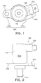
- FIG. 1 is a plan view showing a solenoid valve 100 as a component to be mounted in a structure as one preferred embodiment according to the present invention
- FIG. 2 is a side view of the solenoid valve 100, which is attached to a structure 810 in FIG. 3.
- the solenoid valve 100 is constructed by providing a main body 110 with a projection 120 and a mounting plate portion 130.
- the main body 110 is formed in the shape of, for example, a cylinder or a square cylinder, and has a valve, a solenoid for driving the valve, and the like disposed in an inside thereof.
- a cylindrical fitting shaft portion 111 is coaxially formed, and the fitting shaft portion 111 is fitted into an opening 811 provided in the structure 810.
- the structure 810 has a flow channel for a fluid provided therein and the opening 811 communicates with the inside flow channel. Fitting the fitting shaft portion 111 into the opening 811 enables the solenoid valve 100 to control a flow of the fluid running through the structure 810.
- the projection 120 is formed of a connector or the like connected to the solenoid incorporated in the main body and is disposed so as to protrude from an outer peripheral wall of the main body 110 in the direction of a normal thereto.
- the projection 120 is located such that it interferes with at least either one of bolt inserting holes 131a and 131 b in the mounting plate portion 130 to be later described with respect to the axial center direction of the main body.
- the figures just show a type that causes interference only with one bolt inserting hole 131a.
- the mounting plate portion 130 is fixed at a bottom end of a trunk portion 110a of the main body 110 to mount and fix the main body 110 to the structure 810 with a bolt 820.
- the mounting plate portion 130 is provided, at approximately 180-degrees opposed positions around the main body 110, with a pair of arm pieces 130a and 130b so that they protrude therefrom, and the bolt inserting holes 131a and 131b are formed in these arm pieces 130a and 130b, respectively.
- a notched groove 132 communicating with the bolt inserting hole 131a is formed in at least one arm piece 130a.
- the notched groove 132 extends in a circumferential direction of a circle around the axial center of the fitting shaft portion 111, and is formed to have a groove width equal to or larger than a diameter of the bolt inserting hole 131a.
- the bolt 820 is preliminarily screwed halfway into a bolt screwing hole 812 formed in the structure 810, and in this state, the fitting shaft portion 111 is fitted into the opening 811 of the structure 810 and the main body 110 is rotated. As a result, the bolt 820 can be guidedly introduced through the notched groove into the bolt inserting hole 131a.
- FIG. 3A a primary bolt tightening process is performed in FIG. 3A.
- the bolt 820 is screwed halfway into one bolt screwing hole 812. In this case, the bolt 820 is tightened down to a depth at which a head portion 821 of the bolt 820 does not interfere with the mounting plate portion 130.
- FIG. 3B a process of fitting the main body 110 is performed as shown in FIG. 3B.
- the fitting shaft portion 111 of the main body 110 is fitted into the opening 811 of the structure 810, and the opening 811 is thereby blocked hermetically.
- FIG. 3C a rotating and fitting process is performed as shown in FIG. 3C.
- Rotating the main body 110 around the fitting shaft portion 111 allows the bolt 820 screwed into the bolt screwing hole 812 to be fitted in a proper position of the bolt inserting hole 131a through the notched groove 132.
- FIG. 3D a secondary bolt tightening process is performed as shown in FIG. 3D.
- the bolt 820 screwed into the bolt screwing hole 812 is tightened to a final tightening position. Thereafter, a bolt 820 is screwed also into another bolt screwing hole 812 and tightened, which is not illustrated in FIG. 3.
- the projection 120 such as the connector, as viewed from an axial direction of the solenoid valve, is of a shape that causes interference with the bolt inserting hole 131a formed in the mounting plate portion 130, at the time of an initial bolt tightening, the projection 120 can be moved to a position where the bolt tightening operation is not disturbed.
- the tightening operation can be carried out efficiently.
- the initial bolt tightening operation can be carried out mechanically (automatically), not manually by a worker. In such case, it will be possible to shorten a production cycle time (tact time), thereby leading to an improved productivity and a reduced labor cost.
- FIG. 4A and FIG. 4B show cases where a mounting angle of the projection 120 such as the connector and a mounting position of the arm piece 130a of the mounting plate portion 130 viewed from the axial direction of the main body are different.
- the notched groove 132 is only provided in one arm piece of the mounting plate portion 130, but it can be provided in both of the arm pieces 130a and 130b. This enables both bolts 820 to be preliminarily tightened to a halfway position.
- the mounting plate portion 130 includes the pair of arm pieces 130a and 130b, but it is not limited thereto and can be provided with three or more arm pieces.
- the bolt inserting hole 131b of the other arm piece 130b can be an arc-shaped elongate hole extending in the same circumferential direction as the notched groove 132.
- the bolt 820 may preliminarily be inserted into this elongate hole and primarily tightened, and after an alignment, the bolt 820 may finally be tightened.
Landscapes
- Engineering & Computer Science (AREA)
- General Engineering & Computer Science (AREA)
- Physics & Mathematics (AREA)
- General Physics & Mathematics (AREA)
- Mechanical Engineering (AREA)
- Valve Housings (AREA)
- Magnetically Actuated Valves (AREA)
- Connection Of Plates (AREA)
Applications Claiming Priority (2)
| Application Number | Priority Date | Filing Date | Title |
|---|---|---|---|
| JP2003399750 | 2003-11-28 | ||
| JP2003399750A JP4174800B2 (ja) | 2003-11-28 | 2003-11-28 | ソレノイドバルブ、及びその取付固定方法、並びにソレノイドバルブ、センサ、ポテンショメータ、流量センサその他の付属部品を取付固定するための部品取付固定具 |
Publications (3)
| Publication Number | Publication Date |
|---|---|
| EP1536168A2 true EP1536168A2 (de) | 2005-06-01 |
| EP1536168A3 EP1536168A3 (de) | 2005-07-20 |
| EP1536168B1 EP1536168B1 (de) | 2006-04-12 |
Family
ID=34463887
Family Applications (1)
| Application Number | Title | Priority Date | Filing Date |
|---|---|---|---|
| EP04027446A Expired - Fee Related EP1536168B1 (de) | 2003-11-28 | 2004-11-18 | Montagestruktur und Verfahren zur Montage eines Bauteils in eine Struktur |
Country Status (6)
| Country | Link |
|---|---|
| US (1) | US7131179B2 (de) |
| EP (1) | EP1536168B1 (de) |
| JP (1) | JP4174800B2 (de) |
| AU (1) | AU2004229079B2 (de) |
| DE (1) | DE602004000640T2 (de) |
| ES (1) | ES2262083T3 (de) |
Cited By (2)
| Publication number | Priority date | Publication date | Assignee | Title |
|---|---|---|---|---|
| FR2922025A1 (fr) * | 2007-10-08 | 2009-04-10 | Renault Sas | Dispositif de capteur de choc d'un vehicule automobile et agencement d'un tel dispositif sur un organe automobile |
| EP2743104A3 (de) * | 2012-12-17 | 2014-10-15 | Haldex Brake Products GmbH | Ventil mit einer Befestigungseinrichtung |
Families Citing this family (10)
| Publication number | Priority date | Publication date | Assignee | Title |
|---|---|---|---|---|
| JP4174800B2 (ja) * | 2003-11-28 | 2008-11-05 | カヤバ工業株式会社 | ソレノイドバルブ、及びその取付固定方法、並びにソレノイドバルブ、センサ、ポテンショメータ、流量センサその他の付属部品を取付固定するための部品取付固定具 |
| WO2008004311A1 (fr) * | 2006-07-07 | 2008-01-10 | Toshiaki Kitazawa | Procédé de fabrication de moules et procédés de fabrication d'articles moulés et de produits en acier |
| JP5821546B2 (ja) * | 2011-11-08 | 2015-11-24 | 市光工業株式会社 | 車両用ドアミラー |
| CN202508616U (zh) * | 2012-06-04 | 2012-10-31 | 富鼎电子科技(嘉善)有限公司 | 传感器及采用该传感器的搬运装置 |
| CN103836255B (zh) * | 2012-11-25 | 2017-11-07 | 杭州通产机械有限公司 | 一种安装部件及使用该安装部件的阀结构 |
| US9599067B2 (en) | 2015-06-02 | 2017-03-21 | Zama Japan Kabushiki Kaisha | Attachment structure for solenoid valve to carburetor unit |
| FR3048083B1 (fr) * | 2016-02-22 | 2019-07-19 | Peugeot Citroen Automobiles Sa | Outil de support d’un capteur de regime moteur sur un banc d’essai de moteur |
| CN107919788A (zh) * | 2017-10-11 | 2018-04-17 | 天津中控海容科技有限公司 | 新型变频器防护箱 |
| JP7396924B2 (ja) | 2020-02-14 | 2023-12-12 | アズビル株式会社 | 取付ブラケット |
| CN112343640A (zh) * | 2020-10-10 | 2021-02-09 | 中铁第四勘察设计院集团有限公司 | 地铁车站轨顶风道的装配式安装结构及其施工方法 |
Citations (7)
| Publication number | Priority date | Publication date | Assignee | Title |
|---|---|---|---|---|
| US4893645A (en) * | 1988-11-07 | 1990-01-16 | L. R. Nelson Corporation | Control valve with improved dual mode operation and flow adjustment |
| EP0559197A2 (de) * | 1992-03-04 | 1993-09-08 | Unisia Jecs Corporation | Aufhängungssystemanordnung für ein Kraftfahrzeug |
| FR2743117A1 (fr) * | 1995-12-27 | 1997-07-04 | Valeo Climatisation | Dispositif de fixation d'un motoreducteur sur une paroi dans un appareil de chauffage de vehicule |
| JPH10173402A (ja) * | 1996-12-13 | 1998-06-26 | Nec Corp | 導波管接続フランジ |
| EP0873932A2 (de) * | 1997-04-25 | 1998-10-28 | Kabushiki Kaisha Toyoda Jidoshokki Seisakusho | Anordnung eines Lenkwinkelsensors für ein Rad |
| JP2001056005A (ja) * | 1999-08-12 | 2001-02-27 | Fuji Photo Film Co Ltd | 部材間固定構造及び後露光装置 |
| US6443344B1 (en) * | 2000-05-17 | 2002-09-03 | Harley-Davidson Motor Company Group, Inc. | Securing mechanism for detachable motorcycle component |
Family Cites Families (17)
| Publication number | Priority date | Publication date | Assignee | Title |
|---|---|---|---|---|
| US4524797A (en) * | 1982-02-25 | 1985-06-25 | Robert Bosch Gmbh | Solenoid valve |
| JP2963253B2 (ja) * | 1991-10-07 | 1999-10-18 | 本田技研工業株式会社 | ソレノイドバルブの取付構造 |
| US5333299A (en) * | 1991-12-31 | 1994-07-26 | International Business Machines Corporation | Synchronization techniques for multimedia data streams |
| JP2574748Y2 (ja) * | 1992-03-05 | 1998-06-18 | 住友電気工業株式会社 | ブレーキ液圧制御装置 |
| JP3312449B2 (ja) * | 1993-12-15 | 2002-08-05 | トヨタ自動車株式会社 | 電磁弁 |
| US5457384A (en) * | 1994-04-25 | 1995-10-10 | Honeywell Inc. | Apparatus and method for attaching a sensor to an object |
| US7028978B2 (en) * | 1996-04-15 | 2006-04-18 | Kumar Viraraghavan S | Proportional solenoid-controlled fluid valve having compact pressure-balancing armature-poppet assembly |
| JPH10220626A (ja) * | 1997-02-12 | 1998-08-21 | Toyota Motor Corp | ソレノイド式移動機構及びその製造方法 |
| JP3611969B2 (ja) * | 1998-07-09 | 2005-01-19 | Nok株式会社 | ソレノイド |
| JP2000161151A (ja) * | 1998-11-24 | 2000-06-13 | Mitsubishi Electric Corp | 燃料蒸発ガス排出抑止装置 |
| JP3749026B2 (ja) * | 1998-11-27 | 2006-02-22 | 三菱電機株式会社 | ソレノイドバルブの固定装置 |
| US6182646B1 (en) * | 1999-03-11 | 2001-02-06 | Borgwarner Inc. | Electromechanically actuated solenoid exhaust gas recirculation valve |
| JP2000303811A (ja) * | 1999-04-26 | 2000-10-31 | Denso Corp | 電磁駆動弁装置およびそれを用いた内燃機関 |
| JP4167779B2 (ja) * | 1999-09-24 | 2008-10-22 | 株式会社コガネイ | 電磁弁 |
| JP2002031263A (ja) * | 2000-07-17 | 2002-01-31 | Nok Corp | ソレノイドバルブ |
| JP3796150B2 (ja) * | 2001-09-18 | 2006-07-12 | Smc株式会社 | 保守簡易形2ポート弁 |
| JP4174800B2 (ja) * | 2003-11-28 | 2008-11-05 | カヤバ工業株式会社 | ソレノイドバルブ、及びその取付固定方法、並びにソレノイドバルブ、センサ、ポテンショメータ、流量センサその他の付属部品を取付固定するための部品取付固定具 |
-
2003
- 2003-11-28 JP JP2003399750A patent/JP4174800B2/ja not_active Expired - Fee Related
-
2004
- 2004-11-12 AU AU2004229079A patent/AU2004229079B2/en not_active Ceased
- 2004-11-18 ES ES04027446T patent/ES2262083T3/es active Active
- 2004-11-18 EP EP04027446A patent/EP1536168B1/de not_active Expired - Fee Related
- 2004-11-18 DE DE602004000640T patent/DE602004000640T2/de active Active
- 2004-11-19 US US10/992,100 patent/US7131179B2/en active Active
Patent Citations (7)
| Publication number | Priority date | Publication date | Assignee | Title |
|---|---|---|---|---|
| US4893645A (en) * | 1988-11-07 | 1990-01-16 | L. R. Nelson Corporation | Control valve with improved dual mode operation and flow adjustment |
| EP0559197A2 (de) * | 1992-03-04 | 1993-09-08 | Unisia Jecs Corporation | Aufhängungssystemanordnung für ein Kraftfahrzeug |
| FR2743117A1 (fr) * | 1995-12-27 | 1997-07-04 | Valeo Climatisation | Dispositif de fixation d'un motoreducteur sur une paroi dans un appareil de chauffage de vehicule |
| JPH10173402A (ja) * | 1996-12-13 | 1998-06-26 | Nec Corp | 導波管接続フランジ |
| EP0873932A2 (de) * | 1997-04-25 | 1998-10-28 | Kabushiki Kaisha Toyoda Jidoshokki Seisakusho | Anordnung eines Lenkwinkelsensors für ein Rad |
| JP2001056005A (ja) * | 1999-08-12 | 2001-02-27 | Fuji Photo Film Co Ltd | 部材間固定構造及び後露光装置 |
| US6443344B1 (en) * | 2000-05-17 | 2002-09-03 | Harley-Davidson Motor Company Group, Inc. | Securing mechanism for detachable motorcycle component |
Non-Patent Citations (2)
| Title |
|---|
| PATENT ABSTRACTS OF JAPAN vol. 1998, no. 11, 30 September 1998 (1998-09-30) -& JP 10 173402 A (NEC CORP), 26 June 1998 (1998-06-26) * |
| PATENT ABSTRACTS OF JAPAN vol. 2000, no. 19, 5 June 2001 (2001-06-05) -& JP 2001 056005 A (FUJI PHOTO FILM CO LTD), 27 February 2001 (2001-02-27) * |
Cited By (4)
| Publication number | Priority date | Publication date | Assignee | Title |
|---|---|---|---|---|
| FR2922025A1 (fr) * | 2007-10-08 | 2009-04-10 | Renault Sas | Dispositif de capteur de choc d'un vehicule automobile et agencement d'un tel dispositif sur un organe automobile |
| WO2009080916A1 (fr) * | 2007-10-08 | 2009-07-02 | Renault S.A.S. | Dispositif de capteur de choc d'un véhicule automobile et agencement d'un tel dispositif sur un organe de véhicule automobile. |
| EP2743104A3 (de) * | 2012-12-17 | 2014-10-15 | Haldex Brake Products GmbH | Ventil mit einer Befestigungseinrichtung |
| EP2743104B1 (de) | 2012-12-17 | 2018-01-03 | Haldex Brake Products Aktiebolag | Ventil mit einer Befestigungseinrichtung |
Also Published As
| Publication number | Publication date |
|---|---|
| JP2005163816A (ja) | 2005-06-23 |
| AU2004229079A1 (en) | 2005-06-16 |
| JP4174800B2 (ja) | 2008-11-05 |
| EP1536168A3 (de) | 2005-07-20 |
| ES2262083T3 (es) | 2006-11-16 |
| US20050150099A1 (en) | 2005-07-14 |
| DE602004000640D1 (de) | 2006-05-24 |
| EP1536168B1 (de) | 2006-04-12 |
| AU2004229079B2 (en) | 2006-03-30 |
| DE602004000640T2 (de) | 2006-08-24 |
| US7131179B2 (en) | 2006-11-07 |
Similar Documents
| Publication | Publication Date | Title |
|---|---|---|
| EP1536168B1 (de) | Montagestruktur und Verfahren zur Montage eines Bauteils in eine Struktur | |
| US20060236539A1 (en) | Method of assembling an actuator with an internal sensor | |
| US5749606A (en) | Connector assembly with retainer | |
| KR102045345B1 (ko) | 센서 설치도구 | |
| US7780200B2 (en) | Connecting structure for joint member | |
| US7398704B2 (en) | Sensor assembly and method of assembling a sensor module in a transmission | |
| JP2013015220A (ja) | 油圧マニホールドアセンブリ | |
| US4862760A (en) | Shift lever assembly and method of assembling | |
| US5759064A (en) | Waterproof lamp socket structure | |
| US7510217B2 (en) | Retainer assembly for conduit connection | |
| US11233358B2 (en) | Lever-type connector | |
| US11901776B2 (en) | Adapter for motor replacement and motor replacement method | |
| US4865512A (en) | Industrial robot adjustment device | |
| KR20130018162A (ko) | 액추에이터 부착 회전 밸브와 이 회전 밸브의 액추에이터 | |
| JP2709352B2 (ja) | 弁軸とアクチュエータ駆動軸の結合方法 | |
| JP4024190B2 (ja) | 物品の締結構造 | |
| JP4071081B2 (ja) | 二部材の連結構造 | |
| US5934956A (en) | Mounting arrangement for engine steering cylinder | |
| JP2536757Y2 (ja) | 球接手とスタビライザとの結合構造 | |
| KR102060767B1 (ko) | 자동차용 브레이크 파이프의 회전방지 조립 지그 | |
| CA2254313C (en) | Method and apparatus for screwing a nut onto a shank | |
| JPS6021177Y2 (ja) | ソケットレンチ用のソケット | |
| JP2001205574A (ja) | ドライバ | |
| JPH11201361A (ja) | 分岐管路形成用継手 | |
| JPH09203410A (ja) | ボールジョイントとアームとの結合構造 |
Legal Events
| Date | Code | Title | Description |
|---|---|---|---|
| PUAI | Public reference made under article 153(3) epc to a published international application that has entered the european phase |
Free format text: ORIGINAL CODE: 0009012 |
|
| 17P | Request for examination filed |
Effective date: 20041118 |
|
| AK | Designated contracting states |
Kind code of ref document: A2 Designated state(s): AT BE BG CH CY CZ DE DK EE ES FI FR GB GR HU IE IS IT LI LU MC NL PL PT RO SE SI SK TR |
|
| AX | Request for extension of the european patent |
Extension state: AL HR LT LV MK YU |
|
| PUAL | Search report despatched |
Free format text: ORIGINAL CODE: 0009013 |
|
| AK | Designated contracting states |
Kind code of ref document: A3 Designated state(s): AT BE BG CH CY CZ DE DK EE ES FI FR GB GR HU IE IS IT LI LU MC NL PL PT RO SE SI SK TR |
|
| AX | Request for extension of the european patent |
Extension state: AL HR LT LV MK YU |
|
| GRAP | Despatch of communication of intention to grant a patent |
Free format text: ORIGINAL CODE: EPIDOSNIGR1 |
|
| GRAS | Grant fee paid |
Free format text: ORIGINAL CODE: EPIDOSNIGR3 |
|
| GRAA | (expected) grant |
Free format text: ORIGINAL CODE: 0009210 |
|
| AK | Designated contracting states |
Kind code of ref document: B1 Designated state(s): DE ES |
|
| AKX | Designation fees paid |
Designated state(s): DE ES |
|
| REF | Corresponds to: |
Ref document number: 602004000640 Country of ref document: DE Date of ref document: 20060524 Kind code of ref document: P |
|
| REG | Reference to a national code |
Ref country code: ES Ref legal event code: FG2A Ref document number: 2262083 Country of ref document: ES Kind code of ref document: T3 |
|
| PLBE | No opposition filed within time limit |
Free format text: ORIGINAL CODE: 0009261 |
|
| STAA | Information on the status of an ep patent application or granted ep patent |
Free format text: STATUS: NO OPPOSITION FILED WITHIN TIME LIMIT |
|
| 26N | No opposition filed |
Effective date: 20070115 |
|
| REG | Reference to a national code |
Ref country code: DE Ref legal event code: R082 Ref document number: 602004000640 Country of ref document: DE Representative=s name: GRUENECKER PATENT- UND RECHTSANWAELTE PARTG MB, DE Ref country code: DE Ref legal event code: R081 Ref document number: 602004000640 Country of ref document: DE Owner name: KYB CORPORATION, JP Free format text: FORMER OWNER: KAYABA INDUSTRY CO., LTD., TOKYO, JP |
|
| REG | Reference to a national code |
Ref country code: ES Ref legal event code: PC2A Owner name: KYB CORPORATION Effective date: 20160226 |
|
| PGFP | Annual fee paid to national office [announced via postgrant information from national office to epo] |
Ref country code: DE Payment date: 20181120 Year of fee payment: 15 |
|
| PGFP | Annual fee paid to national office [announced via postgrant information from national office to epo] |
Ref country code: ES Payment date: 20181218 Year of fee payment: 15 |
|
| REG | Reference to a national code |
Ref country code: DE Ref legal event code: R119 Ref document number: 602004000640 Country of ref document: DE |
|
| PG25 | Lapsed in a contracting state [announced via postgrant information from national office to epo] |
Ref country code: DE Free format text: LAPSE BECAUSE OF NON-PAYMENT OF DUE FEES Effective date: 20200603 |
|
| REG | Reference to a national code |
Ref country code: ES Ref legal event code: FD2A Effective date: 20210527 |
|
| PG25 | Lapsed in a contracting state [announced via postgrant information from national office to epo] |
Ref country code: ES Free format text: LAPSE BECAUSE OF NON-PAYMENT OF DUE FEES Effective date: 20191119 |