EP1533870B1 - Piercing terminal for coaxial cable - Google Patents
Piercing terminal for coaxial cable Download PDFInfo
- Publication number
- EP1533870B1 EP1533870B1 EP04027327A EP04027327A EP1533870B1 EP 1533870 B1 EP1533870 B1 EP 1533870B1 EP 04027327 A EP04027327 A EP 04027327A EP 04027327 A EP04027327 A EP 04027327A EP 1533870 B1 EP1533870 B1 EP 1533870B1
- Authority
- EP
- European Patent Office
- Prior art keywords
- piercing
- pair
- insulating layer
- clipping pieces
- terminal
- Prior art date
- Legal status (The legal status is an assumption and is not a legal conclusion. Google has not performed a legal analysis and makes no representation as to the accuracy of the status listed.)
- Expired - Fee Related
Links
Images


Classifications
-
- H—ELECTRICITY
- H01—ELECTRIC ELEMENTS
- H01R—ELECTRICALLY-CONDUCTIVE CONNECTIONS; STRUCTURAL ASSOCIATIONS OF A PLURALITY OF MUTUALLY-INSULATED ELECTRICAL CONNECTING ELEMENTS; COUPLING DEVICES; CURRENT COLLECTORS
- H01R11/00—Individual connecting elements providing two or more spaced connecting locations for conductive members which are, or may be, thereby interconnected, e.g. end pieces for wires or cables supported by the wire or cable and having means for facilitating electrical connection to some other wire, terminal, or conductive member, blocks of binding posts
- H01R11/11—End pieces or tapping pieces for wires, supported by the wire and for facilitating electrical connection to some other wire, terminal or conductive member
-
- H—ELECTRICITY
- H01—ELECTRIC ELEMENTS
- H01R—ELECTRICALLY-CONDUCTIVE CONNECTIONS; STRUCTURAL ASSOCIATIONS OF A PLURALITY OF MUTUALLY-INSULATED ELECTRICAL CONNECTING ELEMENTS; COUPLING DEVICES; CURRENT COLLECTORS
- H01R9/00—Structural associations of a plurality of mutually-insulated electrical connecting elements, e.g. terminal strips or terminal blocks; Terminals or binding posts mounted upon a base or in a case; Bases therefor
- H01R9/03—Connectors arranged to contact a plurality of the conductors of a multiconductor cable, e.g. tapping connections
- H01R9/05—Connectors arranged to contact a plurality of the conductors of a multiconductor cable, e.g. tapping connections for coaxial cables
- H01R9/053—Connectors arranged to contact a plurality of the conductors of a multiconductor cable, e.g. tapping connections for coaxial cables using contact members penetrating insulation
-
- H—ELECTRICITY
- H01—ELECTRIC ELEMENTS
- H01R—ELECTRICALLY-CONDUCTIVE CONNECTIONS; STRUCTURAL ASSOCIATIONS OF A PLURALITY OF MUTUALLY-INSULATED ELECTRICAL CONNECTING ELEMENTS; COUPLING DEVICES; CURRENT COLLECTORS
- H01R9/00—Structural associations of a plurality of mutually-insulated electrical connecting elements, e.g. terminal strips or terminal blocks; Terminals or binding posts mounted upon a base or in a case; Bases therefor
- H01R9/03—Connectors arranged to contact a plurality of the conductors of a multiconductor cable, e.g. tapping connections
- H01R9/05—Connectors arranged to contact a plurality of the conductors of a multiconductor cable, e.g. tapping connections for coaxial cables
Definitions
- the present invention relates to a piercing terminal for a coaxial cable. More specifically, it relates to a piercing terminal suitable for inserting a piercing blade into a coaxial cable to make a conductive connection with an outer conductor-shielding layer.
- Document EP-A-0 419 038 discloses a piercing terminal for a coaxial cable including a core conductor wire, an inner insulating layer for covering the core conductor wire, an outer conductor-shielding layer for covering the inner insulating layer, and an outer insulating layer for covering the outer conductor-shielding layer, wherein the piercing terminal is capable of performing a conductive connection with the outer conductor-shielding layer when a piercing blade comprised in the piercing terminal is embedded in the outer insulating layer to penetrate the outer insulating layer, the piercing terminal comprising: a pair of pieces being arranged to be opposed to each other in a substantially parallel manner; the piercing blade being disposed at a leading end of each of said pair of pieces; and a coupling portion being joined to base portions of said pair of pieces for holding said pair of pieces spaced at a predetermined distance apart; wherein the predetermined distance is larger than an outer diameter of the core conductor wire and smaller than
- Fig. 18 is a view showing a situation where such piercing terminal is press-connected to an outer conductor-plexus-shielding layer of a coaxial cable.
- Fig. 18 hereof corresponds to Fig. 12 of JP-A-2001-223039. As shown in Fig.
- the coaxial cable 150 is composed of: a core conductor wire 151; an inner insulating layer 152 for covering the core conductor wire 151; a cancellate outer conductor-plexus-shielding layer 153 composed of knitted conducting wire for covering the inner insulating layer 152; and an outer insulating layer 154 for covering the outer conductor-plexus-shielding layer 153. Further as shown in Fig. 18, the coaxial cable 150 is locationally adjusted so that a pair of cuspidated portions 101 never comes into contact with the core conductor wire 151 when the U-shaped piercing terminal 100 is embedded into the coaxial cable 150.
- the pair of needle-like cuspidated portions 101 are embedded and penetrate into the outer insulating layer 154, outer conductor-plexus-shielding layer 153, and inner insulating layer 152 sequentially, whereby a conductive connection between the piercing terminal 100 and outer conductor-plexus-shielding layer 153 is established.
- the impedance variation between the core conductor wire and outer conductor-shielding layer of a coaxial cable in the axial direction thereof can be less developed when the piercing terminal is brought into a conductive connection with the coaxial cable.
- the invention provides a piercing terminal arranged as described below.
- a piercing terminal for a coaxial cable including a core conductor wire, an inner insulating layer for covering the core conductor wire, an outer conductor-shielding layer for covering the inner insulating layer, and an outer insulating layer for covering the outer conductor-shielding layer, wherein the piercing terminal is capable of performing a conductive connection with the outer conductor-shielding layer when a piercing blade comprised in the piercing terminal is embedded in the outer insulating layer to penetrate the outer insulating layer, the piercing terminal comprising: a pair of clipping pieces being arranged to be opposed to each other in a substantially parallel manner; the piercing blade being disposed at a leading end of each of said pair of clipping pieces; and a coupling portion being joined to base portions of said pair of clipping pieces for holding said pair of clipping pieces spaced at a predetermined distance apart, wherein each of said pair of clipping pieces comprises a curved portion which is curved outwardly with respect to
- the piercing terminal includes a pair of clipping pieces arranged substantially in parallel with each other and spaced apart at a distance larger than the outer diameter of the core conductor wire and smaller than the outer diameter of the inner insulating layer and piercing blades provided at the leading ends of the pair of clipping pieces. Also, the piercing terminal includes curved portions formed in outwardly convex forms with respect to the pair of clipping pieces, in respective vicinities of the base portions of the pair of clipping pieces.
- the coaxial cable and the piercing terminal can be held in an electrical connection and as such, the impedance between the core conductor wire and the curved portions is made substantially equivalent to the impedance between the core conductor wire and the outer conductor-shielding layer.
- impedance variations in an axial direction of the coaxial cable are less prone to being developed.
- the curved portions may be deformed before the pair of clipping pieces are embedded and penetrate into the outer conductor-shielding layer, thereby changing the direction for piercing and insertion of the pair of clipping pieces. This may make it more difficult to insert the pair of clipping pieces and may cause the pair of clipping pieces to be inserted in a wrong direction thereby to short-circuited with respect to the core conductor wire.
- the pair of clipping pieces may include reinforcing ribs extending from the curved portions toward the leading ends of the clipping pieces.
- the rigidity of the clipping pieces can be increased in order to prevent the aforementioned bend of the pair of clipping pieces due to the formation of the curved portions when the clipping piece are embedded and penetrate into the outer insulating layer.
- the edges of said piercing blades may be disposed closer to the outside of the pair of clipping pieces in the thickness direction of each clipping piece.
- the piercing terminal may be characterized in that the leading end portions of the piercing blades are chamfered on an outer side with respect to the pair of clipping pieces thereby to provide the edges of the pair of piercing blades on the inside in the thickness direction.
- edges of the pair of piercing blades are provided in this way, when the edges are embedded and penetrate into the outer insulating layer, their tapered faces work so that the insertion force causes a force to press the pair of clipping pieces inwardly with respect to the pair of clipping pieces. Therefore, it becomes possible to prevent the distance between the pair of clipping pieces from being widened when the pair of clipping pieces are embedded and penetrate into the outer insulating layer.
- the form defined by inner surfaces of the curved portions provided in the respective pair of clipping pieces arranged opposite to each other may be a cylindrical form which allows the curved portions to be located on a concentric circle of the coaxial cable to enwrap the cable.
- the inner diameter of the cylindrical form defined by the inner surfaces of the curved portions may coincide with the inner diameter of the outer conductor-shielding layer.
- the invention can provide a piercing terminal which can be connected so that no impedance variations are developed in an axial direction of the coaxial cable.
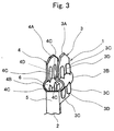
- FIG. 1 is a front view showing a plurality of piercing terminals coupled in series (in the form of a hoop) through a common member in a manufacturing step.
- Fig. 2 is a side view of the coupled piercing terminals illustrated in Fig. 1.
- Fig. 3 is a partial perspective view of the coupled piercing terminals illustrated in Fig. 1.
- the piercing terminals 1 are formed into a form as shown in Fig. 1 by performing cutting, stamping, etc. with respect to a belt-shaped, thin conductive metal sheet, in which the piercing terminals 1 are coupled through a common member 2 at predetermined intervals in series.
- the piercing terminals 1 illustrated in Figs. 1-3 are press-inserted into a first housing part 10 from outside so that coaxial cables 50 (see Fig. 4, for example) can be held inside a housing constituted by the first housing part 10 and a second housing part 20. As a result of the insertion, the piercing terminals 1 are electrically connected to the coaxial cables 50.
- Each of the piercing terminals 1 has a pair of opposed clipping pieces 3, 4, each having a piercing blade for piercing a coaxial cable 50 to insert the clipping pieces therein.
- the opposed clipping pieces 3, 4 in pairs and the coupling portion 5 for coupling base portions of the clipping pieces 3, 4 generally conform to the form of a horseshoe in top view.
- the coupling portion 5 and the clipping pieces 3, 4 define an opening 6 for receiving a coaxial cable 50.
- the opening 6 leads to an accommodation space (a gap between clipping pieces), which is defined by the clipping pieces 3, 4 and is in communication with the outside.
- the piercing blades 3A, 4A are formed by chamfering the leading end portions of the respective clipping pieces 3, 4 into tapers (the leading end portions of the clipping pieces are illustrated on the upper portion in Figs. 1-3).
- a curved portion 3B (4B) illustrated in the lower portion or closer to the base portion thereof in Figs. 1-3, which extends across the width of the clipping piece 3 (4) (or in a horizontal direction of the clipping piece 3 (4) in Fig. 1) and is formed in an outwardly convex shape with respect to the clipping piece 3 (4).
- the formation of the curved portions 3B, 4B may decrease the rigidity of the clipping pieces 3, 4 against the deformation caused by embedding the piercing terminal 1 into a coaxial cable 50. Therefore, the rigidity of the clipping pieces 3, 4 are reinforced by reinforcing ribs 3C, 4C which extend from the respective curved portions 3B, 4B towards the leading ends of the clipping pieces 3, 4 (i.e. the upper ends in the drawing) or towards the rear ends thereof (i.e. the lower end in the drawing) and which arrayed in two rows on outer surfaces of the curved portions 3B, 4B.
- the reinforcing ribs 3C, 4C are formed as convex portions extending toward the leading and rear ends of the clipping pieces 3, 4 with the curved portions 3B, 4B interposed in the respective clipping pieces 3, 4 by press working. As described above, the reinforcing ribs 3C, 4C are arranged in pairs in parallel with each other respectively on the clipping pieces 3, 4. As a result, each pair of the reinforcing ribs 3C (4C) defines a ground-terminal-receiving groove 3D (4D) therebetween.
- a pectinated rectangular flat-plate-shaped ground terminal 40 which is to be described later, can be fitted into the ground-terminal-receiving grooves 3D, 4D.
- the ground-terminal-receiving grooves 3D, 4D each have a width of M. The width M is arranged so as to be identical with or smaller than the width of the ground terminal 40 to allow the insertion of the ground terminal 40.
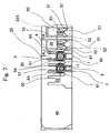
- Fig. 4 is a side, longitudinal sectional view showing the condition where the piercing terminal 1, the press-connecting contact 30, the ground terminal 40 and the coaxial cable 50 are incorporated in the housing composed of a first housing part 10 and a second housing part 20.
- Fig. 5 is a partial sectional view of the pressure connection structure taken along the line A-A in Fig. 4.
- Fig. 6 is a sectional view of the pressure connection structure taken along the line B-B in Fig. 4.
- Fig. 7 is a front view of the pressure connection structure illustrated by Fig. 4.
- the first housing part 10 takes a rectangular form in plane view.
- a plurality of horseshoe-shaped piercing terminal-receptacle holes 13 for the piercing terminals 1 are pierced from the bottom surface 11 to the top surface 12.
- the horseshoe-shaped terminal-receptacle holes 13 are provided in a longitudinal direction of the first housing part 10 at predetermined intervals H, while in a location opposite to the location of the horseshoe-shaped piercing terminal-receptacle hole 13 for each piercing terminal 1 in a shorter side direction of the first housing part 10 is formed a contact-receptacle hole 14 for the press-connecting contact 30, penetrating the first housing part 10 from its bottom surface 11 to the top surface 12.
- a ground-terminal-receptacle hole 15 for receiving the pectinated rectangular flat-plate-shaped ground terminal 40 penetrating the first housing part 10 from its top surface 12 to the bottom surface 11.
- the second housing part 20 has a ground-terminal-receptacle hole 23 formed in a location which agrees with the location of the above-described ground-terminal-receptacle hole 15 when the first and second housing parts 10, 20 are assembled up and down; the ground-terminal-receptacle hole 23 penetrates the second housing part from its top surface 21 to the bottom surface 22 and has the same form as the ground-terminal-receptacle hole 15.
- the second housing part 20 containing the press-connecting contacts 30 is pressed against the first housing part 10 from above it, while the ground terminals 40 are inserted into the ground-terminal-receptacle holes 23, 15, and the piercing terminals 1 are inserted into the horseshoe-shaped terminal-receptacle holes 13, whereby the piercing terminals 1 are assembled to the housing.
- just embedding the piercing terminal 1 into the coaxial cable 50 can electrically connect the outer conductor-shielding layer of the coaxial cable 50 with the ground terminal 40 through the piercing terminal 1.
- the first and second housing parts 10, 20 are made from an insulative material. This connection structure is to be described later in detail.
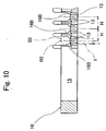
- Fig. 8 is a plane view partially broken away of the first housing part 10.
- Fig. 9 is a front view of the first housing part illustrated by Fig. 8.
- Fig. 10 is a sectional view of the first housing part taken along the line C-C in Fig. 8.
- Fig. 11 is a sectional view of the first housing part taken along the line D-D in Fig. 8.
- the first housing part 10 is composed of an insulative material made by molding of a resin, etc. As described above, the first housing part 10 takes a rectangular form in plane view, and has a plurality of horseshoe-shaped terminal-receptacle holes 13 for piercing terminals 1 pierced therein; the horseshoe-shaped terminal-receptacle holes 13 penetrate the first housing part from its bottom surface 11 to the top surface 12 and are arrayed at predetermined intervals H along a longer side direction of the first housing part 10.
- the first housing part 10 has a cable-receiving groove 16 for each coaxial cable 50 provided in the top surface 12 thereof astride the horseshoe-shaped piercing terminal-receptacle hole 13 and the contact-receptacle hole 14 opposite to the terminal-receptacle hole 13.
- the coaxial cable 50 to be placed in the cable-receiving groove 16 may be widely known one, which is composed of a core conductor wire 51, an inner insulating layer 52 for covering the core conductor wire 51, an outer conductor-shielding layer 53 for covering the inner insulating layer 52, and an outer insulating layer 54 for covering the outer conductor-shielding layer 53, as shown in Fig. 4.
- the coaxial cable 50 has been preprocessed, thereby having made its outer conductor-shielding layer 53 and outer insulating layer 54 stripped off by a predetermined length of L from its leading end and bared the inner insulating layer 52.
- the coaxial cable 50 takes the form of a cable with a shoulder such that the cable has a diameter R1 in a range up to the predetermined length L from its end along its length and has another diameter R2 larger than R1 in the remaining range.
- each cable-receiving groove 16 is composed of: a groove 16A arc-shaped in section having the diameter R1; and a groove 16B arc-shaped in section having the diameter R2.
- the groove 16A lies in a range of from the leading end of the cable-receiving groove 16 to a distance away from the leading end by a length shorter than L, the range including the contact-receptacle hole 14; and the groove 16B lies in the remaining range, i.e. the range starting from a distance away from the leading end by the length L.
- outline-keeping member-receiving grooves 17 each having a predetermined depth for receiving the outline-keeping comb tooth-like member 41 of the ground terminal 40 for keeping the outline of a coaxial cable 50.
- the distance between the outline-keeping comb tooth-like members 41 is set to be smaller than R2 so as to put the a coaxial cable 50 between the outline-keeping comb tooth-like members 41 and hold it from outside the outer insulating layer 54, i.e. a portion of the cable with the largest diameter.
- Fig. 12A is a front view of the ground terminal 40.
- Fig. 12B is a side view of the ground terminal 40.
- the ground terminal 40 is composed of a thin plate made of a metal having an electrically conducting property, and has ground-terminal-holding protrusions 42 respectively provided in two end portions thereof in its longitudinal direction; the protrusions 42 serve to hold the ground terminal 40 in the ground-terminal-receptacle hole 15 after the ground terminal is forced to fit into the hole 15.
- the ground-terminal-holding protrusions 42 make the thickness of the ground terminal 40 larger than the width of the ground-terminal-receptacle hole 23.
- Fig. 7 shows the condition where each coaxial cable 50 is held between the outline-keeping comb tooth-like members 41 from outside a portion of the cable with the largest diameter.
- one protruding portion 43 which has a length shorter than that of the outline-keeping members 41 and serves to force down a coaxial cable 50 from outside a portion of the cable with the largest diameter.
- Fig. 13 is a bottom view of the second housing part.
- Fig. 14 is a sectional view of the second housing part taken along the line E-E in Fig. 13.
- Fig. 15 is a sectional view of the second housing part taken along the line F-F in Fig. 14.
- the second housing part 20 is composed of an insulative material made by molding of a resin, etc.
- the press-connecting contact 30 shaped into a thin rod form is fixed so that its first end 31 is led out from the bottom surface 22 of the second housing part and the second end 32 is led out from a first side 24 of the second housing part 20.
- the first end 31 of the press-connecting contact 30 is electrically connected to the core conductor wire 51 of a coaxial cable 50, and the second end 32 is electrically connected to a wired circuit on an outer circuit board by soldering or connection under pressure.
- the second housing part 20 is provided with a guide groove 26 for placing a coaxial cable 50 thereon,which extends from a second side 25 of the second housing part 20 inwardly, provided that the second side 25 is opposite to the first side 24 from which the press-connecting contact 30 is led out.
- an opening 27 for leading out the first end 31 of each press-connecting contact 30 is formed.
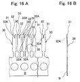
- FIG. 16A is a front view showing the condition where a plurality of press-connecting contacts 30 are coupled to a common member B.
- Fig. 16B is a side view showing the condition illustrated by Fig. 16A.
- Each press-connecting contact 30 has a press-connecting blade 32 formed in a V-like form in front view in a first end 31 of the contact; the press-connecting blade 32 serves to tear a hole in the inner insulating layer 52 of a coaxial cable 50 thereby to electrically connect the press-connecting contact 30 to the core conductor wire 51 of the coaxial cable 50 when the coaxial cable 50 is pressed against the press-connecting blade 32.
- a press-connecting groove 32A for leading and fixing the core conductor wire 51.
- the press-connecting groove 32A is arranged to have a width somewhat smaller than an outer diameter of the core conductor wire 51 in order to maintain a good condition for electrical connection with the core conductor wire 51.
- the press-connecting contacts 30 are individually separated from the common member B, and when the second housing part 20 is molded, each press-connecting contact 30 is partially sealed in the second housing part 20.
- Fig. 17 is a plane view showing a plurality of coaxial cables 50 which have been laminated with a resin sheet and bundled into a wire harness form at predetermined intervals H.
- a plurality of coaxial cables 50 are disposed at the predetermined intervals H on the housing. Then, to the central portion 55 of the plurality of coaxial cables 50 is laminated and bundled into a group of coaxial cables, while two end portion 56 of the group of coaxial cables 50 with respect to the central portion 55 are processed and held with a tape after the leading end portions of the cables have been bared so that the inner insulating layer 52 of thin wire portions of the coaxial cables is exposed to the outside.
- the grouped coaxial cables 50 illustrated by Fig. 17 are disposed in the cable-receiving grooves 16 of the first housing part 10.
- the second housing part 20 is pressed against the first housing part 10 from above it in order to force the individually bared inner insulating layer 52 of each coaxial cable 50 into the press-connecting groove 32A of the corresponding press-connecting contact 30 which is integrally fixed to the second housing part 20 and electrically connect the press-connecting contact 30 to the core conductor wire 51 of the coaxial cable 50.
- piercing terminals 1 are forced into the horseshoe-shaped terminal-receptacle holes 13 from below the first housing part 10, while the ground terminal 40 is forced into the ground-terminal-receptacle hole 15 from above it.
- each piercing terminal 1 includes a pair of opposed clipping pieces 3, 4 which are arranged in parallel and spaced from each other by a small distance larger than the outer diameter r1 of the core conductor wire 51 and smaller than the outer diameter R2 of the inner insulating layer 52.
- Each piercing terminal 1 further includes: piercing blades 3A, 4A formed by chamfering the leading end portions of the clipping pieces 3, 4 into tapers; a pair of curved portions 3B, 4B interposed in the respective clipping pieces 3, 4, each of which is shaped into an outwardly convex form extending across the width of the respective clipping pieces 3, 4; a pair of reinforcing ribs 3C shaped into an outwardly-convex form, arrayed in two rows in parallel in a direction of the width of the clipping piece 3, and extending from the curved portion 3B toward the leading and rear ends of the clipping piece 3 with the curved portion 3B interposed between the reinforcing ribs 3C in each row; and a pair of reinforcing ribs 4C shaped into an outwardly-convex form, arrayed in two rows in parallel in a direction of the width of the clipping piece 4, and extending from the curved portion 4B toward the leading and rear ends of the clipping
- Fig. 4 shows the condition where the piercing terminal 1 and the ground terminal 40 have been forced into the housing.
- a coaxial cable 50 is put between the first and second housing parts 10, 20 and then the piercing terminal 1 is forced into the first housing part 10 from below it, the piercing blades 3A, 4A of the pair of clipping pieces 3, 4 tear holes in the outer insulating layer 54 and outer conductor-shielding layer 53 of the coaxial cable 50, brush against the periphery of the inner insulating layer 52, again tear holes in the outer conductor-shielding layer 53 and outer insulating layer 54 in this order, and protrude from the coaxial cable outwardly under the pressing force produced by inserting the piercing terminal 1.
- the reinforcing function of the reinforcing ribs 3C, 4C prevents the clearance between clipping pieces 3, 4 from outwardly widening, and the inward reduction of the clearance is prevented by making the clipping pieces 3, 4 pinch and hold a protruding portion 43 of the ground terminal 40 forced into the housing from above it. Therefore, the protruding portion 43 is arranged to have a width substantially equal to the clearance between the clipping pieces 3, 4.
- the distance h between the clipping pieces 3, 4 is larger than the outer diameter r1 of the core conductor wire 51 and smaller than the outer diameter R2 of the inner insulating layer 52, more specifically the distance h is somewhat smaller than the outer diameter R2 of the inner insulating layer 52.
- the clipping pieces 3, 4 can slide between the periphery of the inner insulating layer 52 and the outer conductor-shielding layer 53 while brushing against the periphery of the inner insulating layer 52 and then protrude from the coaxial cable outwardly. This makes it possible to avoid the risk that the clipping pieces 3, 4 may short-circuit with the core conductor wire 51.
- the curved portions 3B, 4B are located on the periphery the coaxial cable 50 pinched and hold between the clipping pieces 3, 4, and the center of curvature of the inner diameter of each of the curved portions 3B, 4B shaped into arcs substantially coincides with the center of the coaxial cable 50, and therefore the distance between the outer conductor-shielding layer 53 and core conductor wire 51 of the coaxial cable 50 can be kept substantially constant in a portion of the coaxial cable 50 pinched and held by the clipping pieces 3, 4 as well as in the other portion of the cable.
- the curved portions 3B, 4B of the pair of opposed clipping pieces 3, 4 are provided so as to lie on the same virtual circle and the outer diameter of the curved portions 3B, 4B located on the same virtual circle substantially coincides in size with the inner diameter of the outer conductor-shielding layer 53 taking the form of a tube in section. Accordingly, it can be expected as an advantage that an area for electrical connection between the outer periphery portions of the curved portions 3B, 4B and inner portions lying on a circle formed by the inner diameter of the outer conductor-shielding layer 53 can be ensured sufficiently.
- a piercing terminal for a coaxial cable according to the invention can make the impedance between the core conductor wire of a coaxial cable and the piercing terminal substantially equal to the impedance between the core conductor wire and the outer conductor-shielding layer in the case where the piercing terminal for a cable is connected to the outer conductor-shielding layer of the coaxial cable.
- the piercing terminal for a coaxial cable can further suppress impedance changes in a portion where the piercing terminal for a cable is electrically connected in comparison with other portions of the cable and as such, the application of the piercing terminal to a connector for electrical connection, which has been increasingly reducing in pitch size in recent years, makes possible to avoid impedance changes caused by the connector in a related electrical circuit.
Landscapes
- Coupling Device And Connection With Printed Circuit (AREA)
- Multi-Conductor Connections (AREA)
- Connections By Means Of Piercing Elements, Nuts, Or Screws (AREA)
Applications Claiming Priority (4)
| Application Number | Priority Date | Filing Date | Title |
|---|---|---|---|
| JP2003393020 | 2003-11-21 | ||
| JP2003393020 | 2003-11-21 | ||
| JP2003404848A JP4102295B2 (ja) | 2003-11-21 | 2003-12-03 | 同軸ケーブル用ピアシング端子 |
| JP2003404848 | 2003-12-03 |
Publications (2)
| Publication Number | Publication Date |
|---|---|
| EP1533870A1 EP1533870A1 (en) | 2005-05-25 |
| EP1533870B1 true EP1533870B1 (en) | 2006-09-27 |
Family
ID=34437015
Family Applications (1)
| Application Number | Title | Priority Date | Filing Date |
|---|---|---|---|
| EP04027327A Expired - Fee Related EP1533870B1 (en) | 2003-11-21 | 2004-11-17 | Piercing terminal for coaxial cable |
Country Status (6)
| Country | Link |
|---|---|
| US (1) | US7001203B2 (ko) |
| EP (1) | EP1533870B1 (ko) |
| JP (1) | JP4102295B2 (ko) |
| KR (1) | KR101017045B1 (ko) |
| CN (1) | CN100405662C (ko) |
| DE (1) | DE602004002545T8 (ko) |
Families Citing this family (5)
| Publication number | Priority date | Publication date | Assignee | Title |
|---|---|---|---|---|
| JP3027199U (ja) * | 1996-01-25 | 1996-07-30 | 株式会社新星工業社 | 移動式簡易クローク装置 |
| CN102709717A (zh) * | 2012-01-13 | 2012-10-03 | 加炜电子(昆山)有限公司 | 单芯线连接器端子 |
| DE102013004189B4 (de) * | 2013-03-12 | 2019-07-18 | Sew-Eurodrive Gmbh & Co Kg | Elektrogerät mit Gehäuse und auf dem Gehäuse aufsetzbarem Deckel |
| WO2019032366A1 (en) * | 2017-08-07 | 2019-02-14 | Commscope Technologies Llc | CABLE CONNECTOR BLOCK ASSEMBLIES FOR BASE STATION ANTENNAS |
| JP7249157B2 (ja) * | 2019-01-21 | 2023-03-30 | モレックス エルエルシー | コネクタ端子 |
Family Cites Families (28)
| Publication number | Priority date | Publication date | Assignee | Title |
|---|---|---|---|---|
| US4533191A (en) * | 1983-11-21 | 1985-08-06 | Burndy Corporation | IDC termination having means to adapt to various conductor sizes |
| US4708414A (en) * | 1987-01-30 | 1987-11-24 | Albert Lam | Electric wire connector for coaxial cable |
| JPH0269470U (ko) * | 1988-11-15 | 1990-05-25 | ||
| JP2906469B2 (ja) * | 1989-08-20 | 1999-06-21 | オムロン株式会社 | シールド線用コネクタ |
| US5076800A (en) * | 1991-04-29 | 1991-12-31 | W. L. Gore & Associates, Inc. | Shielded impedance-controlled idc connector |
| JP2665717B2 (ja) * | 1993-10-06 | 1997-10-22 | 日本航空電子工業株式会社 | 同軸コネクタプラグ |
| DE69928274T2 (de) * | 1998-10-15 | 2006-06-01 | Tyco Electronics Corp., Menlo Park | Verbinder für ein elektrisches kabel |
| DE20001912U1 (de) * | 2000-02-03 | 2001-06-13 | Weidmueller Interface | Verbindungs- und/oder Verteilerelement für Schirmkabel |
| JP4308395B2 (ja) | 2000-02-07 | 2009-08-05 | 富士通コンポーネント株式会社 | 同軸ケーブルコネクタ |
| US6379198B1 (en) * | 2000-03-13 | 2002-04-30 | Avaya Technology Corp. | Electrical connector terminal construction |
| JP2003249280A (ja) | 2002-02-27 | 2003-09-05 | Auto Network Gijutsu Kenkyusho:Kk | ピアシング端子 |
| US6524127B2 (en) * | 2001-06-18 | 2003-02-25 | Illinois Tool Works | Insulation displacement connector with reversed bevel cutting edge contacts |
| US6799988B2 (en) * | 2001-07-12 | 2004-10-05 | Leviton Manufacturing Co., Inc. | Insulation displacement electrical connector with spring retainers |
| US6475019B1 (en) * | 2001-07-12 | 2002-11-05 | Leviton Manufacturing Co., Inc. | Insulation displacement electrical connector |
| JP2003077567A (ja) | 2001-09-03 | 2003-03-14 | Auto Network Gijutsu Kenkyusho:Kk | ピアシング端子接続構造 |
| JP2003077568A (ja) | 2001-09-05 | 2003-03-14 | Auto Network Gijutsu Kenkyusho:Kk | ピアシング端子の接続構造 |
| JP2003115340A (ja) | 2001-10-05 | 2003-04-18 | Auto Network Gijutsu Kenkyusho:Kk | ピアシング端子 |
| JP2003115339A (ja) | 2001-10-05 | 2003-04-18 | Auto Network Gijutsu Kenkyusho:Kk | ピアシング端子 |
| JP4067297B2 (ja) | 2001-11-30 | 2008-03-26 | 株式会社オートネットワーク技術研究所 | ピアシング端子接続構造 |
| US6746277B2 (en) * | 2001-12-05 | 2004-06-08 | Tyco Electronics Corporation | Coaxial cable connector |
| JP3979487B2 (ja) | 2002-01-07 | 2007-09-19 | 株式会社オートネットワーク技術研究所 | ピアシング端子の接続構造 |
| JP3942898B2 (ja) | 2002-01-09 | 2007-07-11 | 株式会社オートネットワーク技術研究所 | フレキシブル・フラットケーブルと端子の接続方法及び同接続構造 |
| JP3852920B2 (ja) | 2002-01-09 | 2006-12-06 | 株式会社オートネットワーク技術研究所 | ピアシング端子の接続構造 |
| JP2003243060A (ja) | 2002-02-18 | 2003-08-29 | Auto Network Gijutsu Kenkyusho:Kk | ピアシング端子接続構造 |
| JP3900473B2 (ja) | 2002-03-08 | 2007-04-04 | 株式会社オートネットワーク技術研究所 | ピアシング端子接続構造 |
| JP2003264013A (ja) | 2002-03-11 | 2003-09-19 | Auto Network Gijutsu Kenkyusho:Kk | 撚電線のピアシング端子接続構造 |
| JP4364480B2 (ja) * | 2002-04-10 | 2009-11-18 | 日本圧着端子製造株式会社 | 同軸コネクタ用コンタクトおよびそれを備えた同軸コネクタ |
| JP2003317819A (ja) | 2002-04-24 | 2003-11-07 | Auto Network Gijutsu Kenkyusho:Kk | ピアシング端子接続構造 |
-
2003
- 2003-12-03 JP JP2003404848A patent/JP4102295B2/ja not_active Expired - Fee Related
-
2004
- 2004-11-17 EP EP04027327A patent/EP1533870B1/en not_active Expired - Fee Related
- 2004-11-17 DE DE602004002545T patent/DE602004002545T8/de active Active
- 2004-11-19 US US10/991,874 patent/US7001203B2/en not_active Expired - Fee Related
- 2004-11-19 KR KR1020040095124A patent/KR101017045B1/ko not_active IP Right Cessation
- 2004-11-22 CN CNB2004100914165A patent/CN100405662C/zh not_active Expired - Fee Related
Also Published As
| Publication number | Publication date |
|---|---|
| US7001203B2 (en) | 2006-02-21 |
| US20050130484A1 (en) | 2005-06-16 |
| DE602004002545T2 (de) | 2007-07-05 |
| EP1533870A1 (en) | 2005-05-25 |
| DE602004002545T8 (de) | 2008-08-14 |
| CN100405662C (zh) | 2008-07-23 |
| JP4102295B2 (ja) | 2008-06-18 |
| KR20050049401A (ko) | 2005-05-25 |
| KR101017045B1 (ko) | 2011-02-23 |
| JP2005174552A (ja) | 2005-06-30 |
| CN1619883A (zh) | 2005-05-25 |
| DE602004002545D1 (de) | 2006-11-09 |
Similar Documents
| Publication | Publication Date | Title |
|---|---|---|
| US7976334B2 (en) | Capped insulation displacement connector (IDC) | |
| US7833045B2 (en) | Insulation displacement connector (IDC) | |
| JP2934829B2 (ja) | 改良された導線保持手段を有する電気コネクタ | |
| EP2634862A1 (en) | Cap body insulation displacement connector (IDC) | |
| US7228625B1 (en) | Method for attaching an electrical cable to a connector shield | |
| US20110250783A1 (en) | Cable assembly with improved terminating means and method of making the same | |
| CN111740254A (zh) | 电缆组件、制造电缆组件的方法和设备及用于电缆组件的电气端子 | |
| EP1533868B1 (en) | Pressure connection structure with coaxial cable | |
| US4718865A (en) | Insulated electrical plug | |
| EP1533870B1 (en) | Piercing terminal for coaxial cable | |
| US20110250797A1 (en) | Cable assembly with improved terminating means | |
| US7207829B2 (en) | Electric connector | |
| CN111771307B (zh) | 用于网络连接器的电气屏蔽构件 | |
| US7070442B2 (en) | Structure for press-connecting sheathed electric wire with terminal | |
| US4266843A (en) | Insulation displacing electrical contact and method of making same | |
| KR100316079B1 (ko) | Hf-플러그 타입 커넥터 및 상기 커넥터의 조립 방법 | |
| JP4067297B2 (ja) | ピアシング端子接続構造 | |
| JPH09147929A (ja) | ケーブルコネクタ用コンタクト、コンタクトアセンブリ、多芯ケーブルコネクタおよび圧着工具 | |
| US20040248456A1 (en) | End-processing structure of flat cable and method of end-processing of flat cable | |
| GB2510280A (en) | IDC connector with cap | |
| JP4141414B2 (ja) | 同軸ケーブル用ピアシング端子 | |
| JP2003264013A (ja) | 撚電線のピアシング端子接続構造 | |
| JP3127392B2 (ja) | ケーブルコネクタ | |
| JPH0117238B2 (ko) |
Legal Events
| Date | Code | Title | Description |
|---|---|---|---|
| PUAI | Public reference made under article 153(3) epc to a published international application that has entered the european phase |
Free format text: ORIGINAL CODE: 0009012 |
|
| AK | Designated contracting states |
Kind code of ref document: A1 Designated state(s): AT BE BG CH CY CZ DE DK EE ES FI FR GB GR HU IE IS IT LI LU MC NL PL PT RO SE SI SK TR |
|
| AX | Request for extension of the european patent |
Extension state: AL HR LT LV MK YU |
|
| 17P | Request for examination filed |
Effective date: 20050801 |
|
| AKX | Designation fees paid |
Designated state(s): DE FR GB |
|
| GRAP | Despatch of communication of intention to grant a patent |
Free format text: ORIGINAL CODE: EPIDOSNIGR1 |
|
| GRAS | Grant fee paid |
Free format text: ORIGINAL CODE: EPIDOSNIGR3 |
|
| GRAA | (expected) grant |
Free format text: ORIGINAL CODE: 0009210 |
|
| AK | Designated contracting states |
Kind code of ref document: B1 Designated state(s): DE FR GB |
|
| REG | Reference to a national code |
Ref country code: GB Ref legal event code: FG4D |
|
| REF | Corresponds to: |
Ref document number: 602004002545 Country of ref document: DE Date of ref document: 20061109 Kind code of ref document: P |
|
| ET | Fr: translation filed | ||
| PLBE | No opposition filed within time limit |
Free format text: ORIGINAL CODE: 0009261 |
|
| STAA | Information on the status of an ep patent application or granted ep patent |
Free format text: STATUS: NO OPPOSITION FILED WITHIN TIME LIMIT |
|
| 26N | No opposition filed |
Effective date: 20070628 |
|
| PGFP | Annual fee paid to national office [announced via postgrant information from national office to epo] |
Ref country code: FR Payment date: 20081030 Year of fee payment: 5 |
|
| PGFP | Annual fee paid to national office [announced via postgrant information from national office to epo] |
Ref country code: GB Payment date: 20091030 Year of fee payment: 6 |
|
| PGFP | Annual fee paid to national office [announced via postgrant information from national office to epo] |
Ref country code: DE Payment date: 20091130 Year of fee payment: 6 |
|
| REG | Reference to a national code |
Ref country code: FR Ref legal event code: ST Effective date: 20100730 |
|
| PG25 | Lapsed in a contracting state [announced via postgrant information from national office to epo] |
Ref country code: FR Free format text: LAPSE BECAUSE OF NON-PAYMENT OF DUE FEES Effective date: 20091130 |
|
| GBPC | Gb: european patent ceased through non-payment of renewal fee |
Effective date: 20101117 |
|
| REG | Reference to a national code |
Ref country code: DE Ref legal event code: R119 Ref document number: 602004002545 Country of ref document: DE Effective date: 20110601 Ref country code: DE Ref legal event code: R119 Ref document number: 602004002545 Country of ref document: DE Effective date: 20110531 |
|
| PG25 | Lapsed in a contracting state [announced via postgrant information from national office to epo] |
Ref country code: GB Free format text: LAPSE BECAUSE OF NON-PAYMENT OF DUE FEES Effective date: 20101117 |
|
| PG25 | Lapsed in a contracting state [announced via postgrant information from national office to epo] |
Ref country code: DE Free format text: LAPSE BECAUSE OF NON-PAYMENT OF DUE FEES Effective date: 20110531 |