EP1528135A2 - Dispositif coupe-fil - Google Patents
Dispositif coupe-fil Download PDFInfo
- Publication number
- EP1528135A2 EP1528135A2 EP04025497A EP04025497A EP1528135A2 EP 1528135 A2 EP1528135 A2 EP 1528135A2 EP 04025497 A EP04025497 A EP 04025497A EP 04025497 A EP04025497 A EP 04025497A EP 1528135 A2 EP1528135 A2 EP 1528135A2
- Authority
- EP
- European Patent Office
- Prior art keywords
- thread
- jump
- cutting
- cutting device
- trimmer
- Prior art date
- Legal status (The legal status is an assumption and is not a legal conclusion. Google has not performed a legal analysis and makes no representation as to the accuracy of the status listed.)
- Withdrawn
Links
Images

Classifications
-
- D—TEXTILES; PAPER
- D06—TREATMENT OF TEXTILES OR THE LIKE; LAUNDERING; FLEXIBLE MATERIALS NOT OTHERWISE PROVIDED FOR
- D06C—FINISHING, DRESSING, TENTERING OR STRETCHING TEXTILE FABRICS
- D06C13/00—Shearing, clipping or cropping surfaces of textile fabrics; Pile cutting; Trimming seamed edges
- D06C13/06—Removing floats
Definitions
- the present invention relates to a cutting device for Cut off jump threads, the two consecutive Quilting seams of two quilt sections of a contiguous Connecting ceiling track, at two ends of the jump thread.
- the invention further relates to a device for manufacturing of quilts.
- the industrial production of quilts is generally done by superimposing endless webs of at least an outer material, a filler and an under material to one Linerboard.
- these endless webs by attaching several, usually parallel to each other Stitched seams along the ceiling panel.
- This thread which during the interruption of the sewing process being pulled loosely over the ceiling track is generally considered Called a jump thread. So it's a piece of thread, each from the end of a stitching of a blanket to the beginning of the stitching a next ceiling is enough.
- the object of the invention is to automate this process, to permanently correct severing the jump threads enable.
- the object is achieved by a thread trimmer solved that between a ceiling track and a jump thread is retractable and the cutting elements for cutting the Has a jump thread at the ends.
- the length of the jump thread is known, e.g. 20 cm.
- the approximately Retracted laterally or transversely to the longitudinal axis of the ceiling panel Thread cutter clamps the jump thread and the cutting elements separate the jump thread to the desired, here 20 cm from each other distant places.
- the cutting device an alignment device for aligning the cutting elements immediately adjacent to the ends of the jump thread.
- the thread trimmer introduced between the ceiling track and the jump thread and the cutting elements are aligned that this immediately adjacent to the bolt during the cutting process lie. This will ensure that the jump thread always immediately adjacent to its ends separated will, resulting in increased aesthetic quality of the finished Quilts leads.
- the cutting device a tensioning device for tensioning the jump thread.
- a taut thread is easier to cut than a thread limp thread.
- a tensioning of the jump thread facilitates before severing the jump thread this severing.
- tensioning the hanger makes its ends easier accessible because of such a jig the Jump thread standing opposite the stitching at an angle can be aligned.
- the cutting device a fixing device for fixing the jump thread on.
- a tense one Thread is, as previously mentioned, easier to cut than a flabby.
- the cutting device no longer needs to be precise in the middle of the jump thread are introduced as the cutting the two ends of the jump thread no longer take place simultaneously got to. This will increase the reliability of the cutting process clearly increased.
- the thread trimmer is the Cutter can be inserted transversely to the stitching.
- the alignment device has two movable arms on which the Cutting elements are attached.
- these are movable arms equipped with a spring device, the this spreads.
- Such arms can, e.g. in the leading part of the thread trimmer, be pivoted, and spread to the rear.
- the cutting process takes place when the ends of the jump thread on the cutting elements attached to the arms are to be passed.
- the distance between the cutting elements be varied during the cutting process.
- tolerances in the length range of a certain Length of a jump line but it is too possible, differently long jump threads, such as these, e.g. at different lengths of quilts can occur, cut off, without additional settings necessary.
- the alignment is solely by the two movable arms which are attached to a base body, takes place and no further adjustment devices are necessary,
- the system is also characterized by a special mechanical Simplicity.
- the movable arms at the rear ends each have an eyelet on.
- the thread trimmer has a basic body which is approximately is sword-shaped.
- Such a main body has a tapering forward Front section, an elongated longitudinal beam and followed by a crossbeam.
- the elongated longitudinal beam allows the greatest possible Spreading area for the attached arms.
- the crossbar pushes the ceiling track on a wide surface together and thus makes the ends of the jump thread better accessible.
- the crossbar may still be at its leading edge in addition, have a concave profile, making it as a guide can serve for the movable arms.
- the clamping device is through Covers formed resiliently mounted the cutting elements cover.
- the fixing device acts also as a clamping device.
- the jump thread is passed through the fixing device after retracting the thread trimmer between Deckenbahn and Sprungfaden added and thereby, that the thread trimmer is moved, cocked.
- the fixing device is as Clamp formed.
- the clamp has a forwardly directed inlet opening, in which the thread enters automatically. In a trailing Section of the clamp, the thread is then attached to the thread trimmer fixed.
- the fixing device holds a truncated jump thread.
- the jump thread can after cutting up on easy way to be removed from the ceiling track. remains a cut piece of thread after cutting the Jumping on the ceiling, it may happen that this Thread piece in a further manufacturing step with a Quilt is sewn, which is aesthetically undesirable is.
- the fixing device Means for ejecting a picked-up thread.
- a front edge of the thread trimmer Beveled on her side facing the jump thread.
- the front edge of the Thread cutter protrudes only slightly above the ceiling panel, so that he can easily between the ceiling track and the Jump can be introduced.
- the slope at the Feather facing side of the thread trimmer ensures that while moving the thread trimmer the Jump thread is safely passed over the thread trimmer.
- the invention further relates to a device for manufacturing of quilts, which after a sewing section a thread trimming section comprising a cutting device according to the invention having.
- the manufacturing process can thus be completely automated become.
- the device a Fadenabschneideabsacrificing, in each of which an inventive Thread trimmer over the top and bottom the ceiling track is moved.
- a top and bottom A bobbin thread is used both on the Upper as well as at the bottom of the ceiling web jump threads.
- the jump threads can both at the top and at the bottom of the ceiling in one single operation are removed.
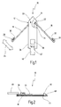
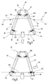
- Fig. 1 is a thread trimmer in its entirety with the Reference numeral 10 denotes.
- the thread trimmer 10 has a base body 12 on which in a front region 14 arms 16 and 18 are mounted.
- the arms 16 and 18 are pivotable through the joints 20 and 22 connected to the main body 12.
- a double arrow 24 indicates in this case an executable by the arm 16 pivotal movement.
- the arms 16 and 18 each have eyelets 26 and 28, on the inside of cutting elements 30 and 32nd are attached.
- a spring 34 acts, which is mounted in the base body 12 is.
- the spring 34 in this case spreads the arm 18 of the Base body 12 from.
- An identical spring acts on the arm 16.
- a spread between the arms 16 and 18 is ensured.
- a clamp 38 attached, which in this embodiment both as a fixing device and as a clamping device acts.
- a Means 40 attached to the thread trimmer 10 via a Ceiling lift can be moved.
- the agent 40 is here as Push rod formed.
- the thread trimmer 10 is through the Screws 42 releasably connected to the means 40.
- FIG. 2 shows a side view of the thread trimmer 10.
- the main body 12 consists of an upper plate 44 and a lower plate 46.
- the upper plate 44 is with a jump thread in contact while the lower plate 46 is in contact with a ceiling track.
- the lower plate 46 further has an upwardly bent Section 48, which forms a beveled nose that the Inserting the thread trimmer 10 between the jump thread and the ceiling track relieved.
- the arm 18 is approximately midway between the upper plate 44 and the lower plate 46 attached.
- the clamp 38 has an opening on a leading side for picking up a jump thread.
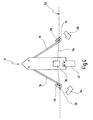
- Fig. 3 the thread trimmer 10 is during a cutting operation shown.
- the thread trimmer 10 is partially in an endless stitching 50 retracted, the first lock stitches 52, a latch 54, a jump thread 56, a second latch 58 and second lock stitches 60 has.
- the latch 54 and 58 are a large number Sewing stitches made in a small space. At the latch 54 is followed by the jump thread 56, the loose the ceiling track that is formed here by the drawing plane, lies. On the left side of the jump thread 56 closes a second latch 58, which has a second row of lock stitches 60 follows.
- the main body 12 of the thread trimmer 10 is in this case between the catapult 56 and a ceiling track through the Drawing plane is formed, retracted.
- the jump thread 56 hangs loosely over the body 12 and the arms 16 and 18 are located in a maximum spread position.
- the thread trimmer 10 is now moved by the means 40 in the direction of arrow 62 moves, with the clamp 38 the jump thread 56 absorbs.
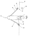
- FIG. 4 shows the thread trimmer 10 of FIG. 3, and that after the in Fig. 3 indicated by the arrow 62 Move.
- the clamp 38 has taken up the jump thread 56 and stretched.
- the jump thread 56 has in the eyelets 26 and 28 of the arms 16 and 18 threaded.
- the cutting element 32 located in the eyelet 28 of the arm 18 is already the right end of Jump thread 56 severed at the height of the bolt 54.
- the arm 18 is no longer under pressure and was stored as springy is deflected in the direction of arrow 68 back to rest position.
- a section of the jump thread 56, which is to the right of the Clamp 38 is no longer connected to the latch 54 and is therefore no longer under tension, but is loose on the ceiling track or the thread trimmer 10.
- a portion of the jump thread 56 to the left of clamp 38 is on its left end still connected to the latch 58. Of the Sprung thread 56 is still fixed in the clamp 38, whereby the portion of the jump thread 56 left of the terminal 38 still is under tension.
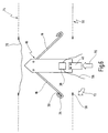
- Fig. 6 shows the thread trimmer 10 of Fig. 5, both Ends of the jump thread 56 were severed.
- the cutting element 30 mounted in the eyelet 26 has severed the left end of the jump thread at the height of the bolt 58.
- the jump thread 56 is now completely from the stitching 50th detached and hangs trapped in the clamp 38.
- the thread trimmer 10 can now by the means 40 in the direction of the arrow 70 in the direction of a second stitching 74 moves become.
- the second stitching 74 has a second one Jump thread 76 on. This can be a second cutting process be effected.
- the thread trimmer 10 overflows the entire ceiling track, separates all the jump threads that are trapped in the clamp.
- the trapped jump threads may e.g. through a compressed air nozzle be blown out at the terminal for discharging.
- the thread trimmer is then moved back, the ceiling track to move on to an appropriate piece and then you can further separation process done.
- Fig. 7 is a second embodiment of a thread trimmer designated in its entirety by the reference numeral 80.
- the thread trimmer 80 has a main body 82, which the Shape of a trapezoid has.
- the front edge 84 of the main body 82nd here forms the short parallel of the trapezoid, while side edges 86 and 88 are the non-parallel sides of the trapezoid form.
- the trailing edge 90 forms the long parallel of the trapezoid.
- the covers 92 and 94 are by the springs 96 and 98 and 100 and 102 with fasteners 104, 106, 108 and 110, respectively connected, which are attached to the base 82. Consequently are the covers 92 and 94 relative to the main body 82nd spring-mounted.
- cutting elements 112 and 114 which are formed as elongated blades are.
- the cutting elements 112 and 114 are for the most part covered by the covers 92 and 94.
- a means 116 is detachable with the Main body 82 connected. With the means 116, the thread trimmer 80 via a ceiling track in the direction of arrow 118 to be moved.
- the thread trimmer 80 is partially in an endless stitching 120 retracted, the first lockstitch 122, followed by a first latch 124, a jump thread 126, a second latch 128 and second lock stitches 130.
- the thread trimmer 80 is in this case under the jump thread 126 retracted.
- the covers 92 and 94 are at rest, i.e. they stand over the respective side edges 86 and 88 out.
- the springs 96 and 98, with the cover 92 are connected, and the springs 100 and 102, with the cover 94 are also in hibernation.
- the jump thread 126 lies loosely on the thread trimmer 80th
- FIG. 8 shows the thread trimmer 80 of FIG. 7, namely, according to the direction indicated in Fig. 7 movement of the arrow 118.
- the tensioned jump thread 126 causes a pressure on the cover 94.
- the cover 94 partially in Direction of the arrow 132 shifted, causing the cutting element 114 of the side edge 88 is exposed.
- the spring 102 is by moving the cover 94 compressed.
- a front portion of the cutting element 114 remains from the Cover 94 obscured, causing the ceiling panel in front of an unwanted Cutting is protected.
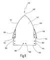
- Fig. 9 is a third embodiment of a thread trimmer designated in its entirety by the reference numeral 140.
- the thread trimmer 140 has a main body 142 which has two side edges 144 and 146. The two side edges converge crooked to a peak 148. At the trailing End of the main body 142 is a trailing edge 150, which is currently being trained.
- the main body 142 has such a Shape similar to that of an iron.
- the cutting elements 152 and 154 have at their outer edges Blades 156 and 158, which are curved in this case and approximately follow the contour of the side edges 144 and 146.
- the cutting elements 152 and 154 are removed from the body 142. Thereby the cutting elements 152 and 154 can be exchanged, e.g. when the blades 156 and 158 are dull.
- the cutting elements 152 and 154 may also be in another Position, e.g. indicated by the holes 162 and 164 is attached to the main body 142. This allows the Distance between the two blades 156 and 158 changed from each other become when severing jump threads of different length should be.
- the base 142 has holes 166 and 168, with which the thread trimmer 140 at a Means can be attached by the thread trimmer 140 can be moved over a ceiling track.
- the thread trimmer 140 is mechanically very simple, but only little flexible, so he is best for uses is suitable for those over long periods equally long jump threads be cut off.
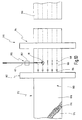
- Fig. 10 is an apparatus for producing quilts provided in their entirety by the reference numeral 170.
- the apparatus 170 for making quilts has a Feed section 172, in the endless webs of a substrate 174, a filler 176 and an outer fabric 178 on top of each other are laid, whereby a ceiling track 180 is formed.
- the ceiling panel 180 is fed to a sewing section 182. Of the Sewing section 182 has sewing machines 184 along the Ceiling panel 180 install five parallel stitching 186. These parallel stitching 186 are at regular intervals of Jump threads 188 interrupted.
- the thread trimming section 190 points a drive 192 having a means 40 across the ceiling track 180 moves.
- the means 40 is a one sliding rod.
- Thread trimmer 10 At the end of the means 40 is the Thread trimmer 10, here about more than a third of the ceiling track is moved.
- the cutting portion 194 in which the ceiling panel 180 to individual Quilts 196 is tailored. This cut is done here in the middle of the interruptions in the stitching 186 resulting after removal of the jump threads 188.
Landscapes
- Engineering & Computer Science (AREA)
- Textile Engineering (AREA)
- Treatment Of Fiber Materials (AREA)
- Sewing Machines And Sewing (AREA)
Applications Claiming Priority (2)
| Application Number | Priority Date | Filing Date | Title |
|---|---|---|---|
| DE10351889 | 2003-10-30 | ||
| DE2003151889 DE10351889B4 (de) | 2003-10-30 | 2003-10-30 | Fadenabschneider |
Publications (2)
| Publication Number | Publication Date |
|---|---|
| EP1528135A2 true EP1528135A2 (fr) | 2005-05-04 |
| EP1528135A3 EP1528135A3 (fr) | 2006-02-15 |
Family
ID=34399689
Family Applications (1)
| Application Number | Title | Priority Date | Filing Date |
|---|---|---|---|
| EP04025497A Withdrawn EP1528135A3 (fr) | 2003-10-30 | 2004-10-27 | Dispositif coupe-fil |
Country Status (2)
| Country | Link |
|---|---|
| EP (1) | EP1528135A3 (fr) |
| DE (1) | DE10351889B4 (fr) |
Cited By (2)
| Publication number | Priority date | Publication date | Assignee | Title |
|---|---|---|---|---|
| CN105397960A (zh) * | 2015-11-30 | 2016-03-16 | 芜湖德鑫汽车部件有限公司 | 安全修剪工装 |
| CN109123865A (zh) * | 2018-08-23 | 2019-01-04 | 广东溢达纺织有限公司 | 剪线折叠机及剪线折叠方法 |
Families Citing this family (1)
| Publication number | Priority date | Publication date | Assignee | Title |
|---|---|---|---|---|
| CN107475977B (zh) * | 2017-09-30 | 2019-10-01 | 宁波源生针织有限公司 | 针织布线头的清理方法 |
Family Cites Families (3)
| Publication number | Priority date | Publication date | Assignee | Title |
|---|---|---|---|---|
| US3559600A (en) * | 1970-01-21 | 1971-02-02 | Mathewson Corp | Quilting apparatus |
| JP2872961B2 (ja) * | 1995-04-20 | 1999-03-24 | 株式会社ハシマ | キルティングマシン |
| GB9911521D0 (en) * | 1999-05-19 | 1999-07-14 | Kyle James | Thread trimming apparatus and method |
-
2003
- 2003-10-30 DE DE2003151889 patent/DE10351889B4/de not_active Expired - Fee Related
-
2004
- 2004-10-27 EP EP04025497A patent/EP1528135A3/fr not_active Withdrawn
Cited By (3)
| Publication number | Priority date | Publication date | Assignee | Title |
|---|---|---|---|---|
| CN105397960A (zh) * | 2015-11-30 | 2016-03-16 | 芜湖德鑫汽车部件有限公司 | 安全修剪工装 |
| CN109123865A (zh) * | 2018-08-23 | 2019-01-04 | 广东溢达纺织有限公司 | 剪线折叠机及剪线折叠方法 |
| CN109123865B (zh) * | 2018-08-23 | 2023-10-13 | 广东溢达纺织有限公司 | 剪线折叠机及剪线折叠方法 |
Also Published As
| Publication number | Publication date |
|---|---|
| DE10351889A1 (de) | 2005-06-09 |
| EP1528135A3 (fr) | 2006-02-15 |
| DE10351889B4 (de) | 2007-05-03 |
Similar Documents
| Publication | Publication Date | Title |
|---|---|---|
| EP2336413B1 (fr) | Machine à broder à blocs à aiguilles multiples, bloc à aiguilles multiples pour cette machine, ainsi qu'élément coupe fil et coupe-fil pour cette machine | |
| DE102006017871B4 (de) | Vorrichtung zum Verhindern des Auftrennens von Nähten und Verfahren hierzu | |
| DE69713416T2 (de) | Verfahren und Vorrichtung zur Vermeidung von Nahtlockerung in einer Doppelkettenstichnähmaschine | |
| DE3116931C2 (de) | Vorrichtung an Nähmaschinen zum Ausziehen und Abschneiden der Fäden | |
| DE2313717B2 (de) | Einrichtung zur Herstellung von Paspelöffnungen in Zuschnitteilen von Bekleidungsstücken | |
| DE7020068U (de) | Vorrichtung an naehmaschinen zum fuehren der fadenkette. | |
| DE2103791C3 (de) | Doppelsteppstich-Nähmaschine | |
| DE10351889B4 (de) | Fadenabschneider | |
| DE69807591T2 (de) | Verfahren und Vorrichtung zum Ausriffeln von Fäden | |
| DE69804316T2 (de) | Nähverfahren und nähmaschine die das freimachen einer ziehschnur aus einer durch eine nähnaht geformte passage ermöglicht | |
| DE2442264C3 (de) | Schneideinrichtung für eine Nähmaschine | |
| DE2446601A1 (de) | Vorrichtung zum annaehen der beiden baender eines reissverschlusses | |
| DE1813057B2 (de) | Zusatzvorrichtung ffir eine Knopfannähmaschine | |
| DE1160976B (de) | Fadenschneidvorrichtung fuer Strumpfrundstrickmaschinen | |
| DE1288892B (de) | Zweifaden-UEberwendlichnaehmaschine zur Verbindung eines elastischen Bandes mit einem Werkstueck | |
| EP0023950A1 (fr) | Dispositif de coupe | |
| CH618749A5 (en) | Knitting machine | |
| DE3830772C2 (fr) | ||
| DD267069A5 (de) | Verfahren und einrichtung zum fuehren der schussfaeden bei webmaschinen | |
| DE2341234A1 (de) | Webmaschine | |
| DE822758C (de) | Zweifaden-Naehmaschine | |
| EP0197275B1 (fr) | Procédé et métier à tricoter chaîne rectiligne pour la fabrication d'un tricot chaîne à trames | |
| DE3513112C2 (fr) | ||
| DE102013105973B4 (de) | Vorrichtung und Verfahren zum Trennen flottierender Fäden einer Warenbahn | |
| DE1240248B (de) | Vorhang od. dgl. |
Legal Events
| Date | Code | Title | Description |
|---|---|---|---|
| PUAI | Public reference made under article 153(3) epc to a published international application that has entered the european phase |
Free format text: ORIGINAL CODE: 0009012 |
|
| AK | Designated contracting states |
Kind code of ref document: A2 Designated state(s): AT BE BG CH CY CZ DE DK EE ES FI FR GB GR HU IE IT LI LU MC NL PL PT RO SE SI SK TR |
|
| AX | Request for extension of the european patent |
Extension state: AL HR LT LV MK |
|
| PUAL | Search report despatched |
Free format text: ORIGINAL CODE: 0009013 |
|
| AK | Designated contracting states |
Kind code of ref document: A3 Designated state(s): AT BE BG CH CY CZ DE DK EE ES FI FR GB GR HU IE IT LI LU MC NL PL PT RO SE SI SK TR |
|
| AX | Request for extension of the european patent |
Extension state: AL HR LT LV MK |
|
| AKX | Designation fees paid | ||
| STAA | Information on the status of an ep patent application or granted ep patent |
Free format text: STATUS: THE APPLICATION IS DEEMED TO BE WITHDRAWN |
|
| 18D | Application deemed to be withdrawn |
Effective date: 20060817 |
|
| REG | Reference to a national code |
Ref country code: DE Ref legal event code: 8566 |