EP1516803B1 - Fahrzeug-Motorhaube - Google Patents
Fahrzeug-Motorhaube Download PDFInfo
- Publication number
- EP1516803B1 EP1516803B1 EP04022457A EP04022457A EP1516803B1 EP 1516803 B1 EP1516803 B1 EP 1516803B1 EP 04022457 A EP04022457 A EP 04022457A EP 04022457 A EP04022457 A EP 04022457A EP 1516803 B1 EP1516803 B1 EP 1516803B1
- Authority
- EP
- European Patent Office
- Prior art keywords
- hood
- vehicle
- inner panel
- longitudinal direction
- portions
- Prior art date
- Legal status (The legal status is an assumption and is not a legal conclusion. Google has not performed a legal analysis and makes no representation as to the accuracy of the status listed.)
- Expired - Lifetime
Links
Images


Classifications
-
- B—PERFORMING OPERATIONS; TRANSPORTING
- B62—LAND VEHICLES FOR TRAVELLING OTHERWISE THAN ON RAILS
- B62D—MOTOR VEHICLES; TRAILERS
- B62D25/00—Superstructure or monocoque structure sub-units; Parts or details thereof not otherwise provided for
- B62D25/08—Front or rear portions
- B62D25/10—Bonnets or lids, e.g. for trucks, tractors, busses, work vehicles
- B62D25/105—Bonnets or lids, e.g. for trucks, tractors, busses, work vehicles for motor cars
-
- B—PERFORMING OPERATIONS; TRANSPORTING
- B60—VEHICLES IN GENERAL
- B60R—VEHICLES, VEHICLE FITTINGS, OR VEHICLE PARTS, NOT OTHERWISE PROVIDED FOR
- B60R21/00—Arrangements or fittings on vehicles for protecting or preventing injuries to occupants or pedestrians in case of accidents or other traffic risks
- B60R21/34—Protecting non-occupants of a vehicle, e.g. pedestrians
- B60R2021/343—Protecting non-occupants of a vehicle, e.g. pedestrians using deformable body panel, bodywork or components
Definitions
- the present invention relates to a vehicle hood structure, and in particular, to a vehicle hood structure which is used in a vehicle such as an automobile or the like and which protects a colliding body at the time of a collision.
- a structure which is applied to a vehicle such as an automobile or the like, a structure is conventionally known in which the interval between a hood outer panel and a hood inner panel is made to be larger at the rear half portion of the hood in the vehicle longitudinal direction than at the front half portion thereof (see, for example, Japanese Patent Application Laid-Open ( JP-A) No. 11-321713 ).
- the front half portion of the hood has low rigidity, and the general properties intrinsic to the hood (torsional rigidity, tensile rigidity, and the like) are poor. Further, at the rear half portion of the hood, the interval between the hood inner panel and the members beneath the hood is narrower than at the front half portion.
- the hood inner panel deforms locally, and the amount of energy absorbed at the time of the primary collision cannot be ensured.
- WO 02/47961 A1 discloses a vehicle hood structure in which a hood inner panel has one of a wavy cross-sectional configuration and a hat-shaped frame cross-sectional configuration, to realize a head collision resistance which is independent of the collision position against the hood, and to provide the vehicle hood structure with tension rigidity, bending rigidity and torsional rigidity.
- an object of the present invention is to provide a vehicle hood structure in which energy is sufficiently absorbed at the time of a primary collision, and the impact received by a colliding body due to a secondary collision can be lessened.
- shelf portions are formed along the vehicle longitudinal direction at side wall portions of the wavy cross-sectional configuration. Owing to these shelf portions, the rigidity of the hood is increased, and accordingly, sufficient energy absorption at the time of a primary collision is possible. As a result, the impact which a colliding body receives at the time of a secondary collision can be reduced.
- recessed beads are formed along the vehicle longitudinal direction at peak portions of the wavy cross-sectional configuration. Owing to the recessed beads, the rigidity of the hood is increased, and accordingly, sufficient energy absorption is possible over a wide range in which local deformation at the time of a primary collision is suppressed. As a result, the impact which a colliding body receives at the time of a secondary collision can be reduced.
- a first embodiment of a vehicle hood structure of the present invention will be described in accordance with Figs. 1 through 7 .
- arrow UP designates the upward direction of the vehicle
- arrow FR designates the front direction of the vehicle
- arrow IN designates the direction toward the vehicle interior along the vehicle transverse direction.
- a hood 10 of the present embodiment has a hood outer panel 12 which structures the vehicle body outer side surface of the hood 10, and a hood inner panel 14 which is disposed over the entirety of the hood inner side (the reverse surface side) of the hood outer panel 12 and structures the inner side portion of the hood 10, such that the hood 10 is a completely hollow structure.
- a plurality of convex portions 18 are formed along the vehicle longitudinal direction at predetermined intervals in the vehicle transverse direction, at a central region 14E of the hood inner panel 14, which is other than a front end edge portion 14A, a rear end edge portion 14B, and left and right vehicle transverse direction outer side edge portions 14C, 14D which are the outer peripheral edge portions of the hood inner panel 14.
- flanges 12A are formed so as to be directed toward the bottom of the vehicle body at the vehicle transverse direction both end portions of the hood outer panel 12.
- the flanges 12A are connected to flanges 14F which are formed so as to be directed toward the bottom of the vehicle body at the vehicle transverse direction both end portions of the hood inner panel 14.
- the convex portions 18 of the hood inner panel 14 swell toward the top of the vehicle body. Central portions, in the vehicle transverse direction, of peak portions 18A of the convex portions 18 are joined to a reverse surface 12B of the hood outer panel 12 by an adhesive 20.
- the convex portions 18 of the hood inner panel 14 extend from the front end portion of the central region 14E to the rear end portion thereof.
- a border line L is set at the hood inner panel 14 of the hood 10 at the intermediate portion thereof in the longitudinal direction of the vehicle.
- the portion of the hood inner panel 14 at the front side of this border line L is front half portion 22, and the portion at the rear side of the border line L is rear half portion 24.
- the border line L is formed, in plan view, in the shape of an arc which runs along a front end edge portion 10A of the hood 10,
- Shelf portions 30 serving as rigidity strengthening portions are formed along the vehicle longitudinal direction at the vertical direction intermediate portions of side wall portions 18B, whose cross-sectional configurations are wavy, of the convex portions 18 at the front half portion 22 of the hood inner panel 14 shown in Fig. 1 .
- Shelf portion 32 serving as rigidity strengthening portions are formed along the vehicle longitudinal direction at the vertical direction intermediate portions of the convex portions 18 at the rear half portion 24 of the hood inner panel 14 shown in Fig. 2 .
- a vehicle transverse direction width W2 of the shelf portion 32 at the rear half portion 24 of the hood inner panel 14 is smaller as shown in Fig. 2 (W1 > W2).
- a member 40 positioned beneath the hood inner panel 14 is a rigid body such as the engine or the like.
- the shelf portions 30 are formed along the vehicle longitudinal direction at the side wall portions 18B of the convex portions 18. Therefore, owing to these shelf portions 30, the rigidity of the front half portion 22 of the hood inner panel 14 is increased. As a result, at the front half portion 22 of the hood inner panel 14, sufficient energy absorption at the time of a primary collision is possible, and therefore, the impact received by a colliding body K1 due to a secondary collision can be lessened.
- the width W2, in the vehicle transverse direction, of the shelf portion 32 at the rear half portion 24 of the hood inner panel 14 is narrow as compared with the width W1, in the vehicle transverse direction, of the shelf portion 30 at the front half portion 22 of the hood inner panel 14 (W1 > W2).
- the amount of deformation, toward the bottom of the vehicle, of the hood 10 at the rear half portion 24 of the hood inner panel 14 which portion tends to be collided by the colliding body K2 having a large mass can be controlled not to be so large as compared with the amount of deformation, toward the bottom of the vehicle, of the hood 10 at the front half portion 22 of the hood inner panel 14 which portion tends to be collided by the colliding body K1 having a small mass.
- the impact which the colliding body K2 receives due to a secondary collision can be decreased over the entire region of the hood 10 corresponding to the front half portion 22 and the rear half portion 24 of the hood inner panel 14.
- the hood 10 illustrated in Fig. 4 is a completely hollow structure.
- a structure may be used in which a hood inner panel 33 of the hood 10 is disposed along the reverse surface 12B of the hood outer panel 12, and the cross-sectional configuration, as seen from the vehicle longitudinal direction, is a hat-shaped frame (skeleton) structure whose open portion is directed upwardly, and the shelf portions 30, 32 are formed respectively along the vehicle longitudinal direction at side wall portions 33A of the hat-shaped cross-sectional configuration.
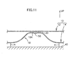
- recessed beads (beads which are concave toward the bottom of the vehicle body) 50 serving as rigidity strengthening portions are formed along the vehicle longitudinal direction at the vehicle transverse direction central portions of the peak portions 18A of the convex portions 18.
- the cross-sectional configuration of the recessed bead 50 shown in Fig. 11 is arc-shaped.
- the recessed bead 50 is a liquid pooling portion for a mastic adhesive which is used as the adhesive 20 for adhering the hood inner panel 14 and the hood outer panel 12 together.
- the recessed beads 50 are formed along the vehicle longitudinal direction at the vehicle transverse direction central portions of the peak portions 18A of the convex portions 18. Therefore, the rigidity of the front half portion 22 of the hood inner panel 14 is increased by these recessed beads 50. As a result, at the front half portion 22 of the hood inner panel 14, sufficient energy absorption at the time of a primary collision is possible, and therefore, the impact which the colliding body receives due to the secondary collision can be reduced.
- the recessed beads 50 are formed at the peak portions 18A of the convex portions 18.
- the rise at the initial stage of the collision is fast and the acceleration of the primary peak P1 is high therein, as compared with the change in the acceleration G2 in relation to the stroke S of the colliding body in a structure in which the recessed beads 50 are not formed. Accordingly, energy can be absorbed efficiently at the stage when the collision speed of the colliding body is fast. Therefore, when a colliding body collides with the member 40 under the hood, the acceleration G 1 is a low, stable wave-shape, and not a wave-shape having a floor such as the acceleration G2.
- the impact which a colliding body receives due to a secondary collision can be decreased over the entire region of the hood 10 corresponding to the front half portion 22 and the rear half portion 24 of the hood inner panel 14.
- the recessed beads 50 which are formed at the peak portions 18A of the convex portions 18 of the hood inner panel 14 can be used as liquid pooling portions for the mastic adhesive which is used as the adhesive 20 for adhering the hood inner panel 14 and the hood outer panel 12 together.
- a structure may be used in which the angles of inclination of the shelf portions 30 at the front half portion 22 of the hood inner panel 14 and the angles of inclination of the shelf portions 32 at the rear half portion 24 of the hood inner panel 14 are different.
- shelf portions 30 at the front half portion 22 of the hood inner panel 14 and the shelf portions 32 at the rear half portion 24 of the hood inner panel 14 may be formed in the same configurations.
- recessed beads 50 of the second embodiment are formed at the peak portions 18A of the convex portions 18 having the shelf portions 30, 32 of the first embodiment, such that control of the impact absorbing ability can be improved even more.
Landscapes
- Engineering & Computer Science (AREA)
- Mechanical Engineering (AREA)
- Chemical & Material Sciences (AREA)
- Combustion & Propulsion (AREA)
- Transportation (AREA)
- Superstructure Of Vehicle (AREA)
Claims (8)
- Fahrzeughaube mit:einem Außenblech (12), das eine Außenoberfläche einer Haube (10) bildet;einem über den gesamten Bereich der Rückseite des Außenblechs (12) angeordneten Innenblech (14), das in Fahrzeuglängsrichtung betrachtet entweder eine im Querschnitt wellenförmige Struktur, die von einer Vielzahl von konvexen Abschnitten (18) in Fahrzeuglängsrichtung in vorgegebenen Abständen in Fahrzeugbreitenrichtung definiert ist, oder eine nach oben geöffnete im Querschnitt hutförmige Rahmenstruktur aufweist; undeiner Versteifung (30, 32), die in Fahrzeuglängsrichtung an den Seitenwänden (18B, 33A) der wellenförmigen Struktur oder der hutförmigen Struktur des Innenblechs (14) durch Verformung eines Abschnitts des Innenblechs (14) ausgebildet ist, dadurch gekennzeichnet, dassdie Seitenwände (18B, 33A) jeweils eine im Querschnitt wellenförmige Struktur aufweisen und in ihrem in Vertikalrichtung mittleren Bereich einen Absatz definieren, der die Versteifung (30, 32) bildet.
- Fahrzeughaube nach Anspruch 1, wobei eine Breite W2 der
Absätze (32) in Fahrzeugbreitenrichtung in der in Fahrzeuglängsrichtung hinteren Hälfte (24) des Innenblechs (14) kleiner ist als eine Breite W1 der Absätze (30) in Fahrzeugbreitenrichtung in der in Fahrzeuglängsrichtung vorderen Hälfte (22) des Innenblechs (14). - Fahrzeughaube nach Anspruch 1, wobei eine Breite W2 der
Absätze (32) in Fahrzeugbreitenrichtung in der in Fahrzeuglängsrichtung hinteren Hälfte (24) des Innenblechs (14) gleich einer Breite W1 der Absätze (30) in Fahrzeugbreitenrichtung in der in Fahrzeuglängsrichtung vorderen Hälfte (22) des Innenblechs (14) ist. - Fahrzeughaube nach Anspruch 1, wobei eine Breite W2 der Absätze (32) in Fahrzeugbreitenrichtung in der in Fahrzeuglängsrichtung hinteren Hälfte (24) des Innenblechs (14) größer ist als eine Breite W1 der Absätze (30) in Fahrzeugbreitenrichtung in der in Fahrzeuglängsrichtung vorderen Hälfte (22) des Innenblechs (14).
- Fahrzeughaube nach einem der Ansprüche 1 bis 4, wobei die
Neigungswinkel der Absätze (30) in der in Fahrzeuglängsrichtung vorderen Hälfte (22) des Innenblechs (14) von den Neigungswinkeln der Absätze (32) in der in Fahrzeuglängsrichtung hinteren Hälfte (24) des Innenblechs (14) verschieden sind. - Fahrzeughaube nach einem der Ansprüche 1 bis 5, wobei das Innenblech
(14) eine im Querschnitt wellenförmige Struktur hat und in den Scheitelbereichen (18a) der im Querschnitt wellenförmigen Struktur in Fahrzeuglängsrichtung verlaufende Sicken (50) ausgebildet sind. - Fahrzeughaube mit:einem Außenblech, das eine Außenoberfläche einer Haube (10) bildet; undeinem über den gesamten Bereich der Rückseite des Außenblechs (12) angeordneten Innenblech (14), das in Fahrzeuglängsrichtung betrachtet eine im Querschnitt wellenförmige Struktur aufweist, die von einer Vielzahl von konvexen Abschnitten (18) in Fahrzeuglängsrichtung in vorgegebenen Abständen in Fahrzeugbreitenrichtung definiert ist, dadurch gekennzeichnet, dassin den Scheitelbereichen der konvexen Abschnitte (18) des Innenblechs (14) Sicken (50) in Fahrzeuglängsrichtung ausgebildet sind.
- Fahrzeughaube nach Anspruch 7, des Weiteren mit Absätzen (30, 32), die in Fahrzeuglängsrichtung an den Seitenwänden der in Vertikalrichtung mittleren Bereiche der konvexen Abschnitte (18) ausbildet sind.
Applications Claiming Priority (2)
| Application Number | Priority Date | Filing Date | Title |
|---|---|---|---|
| JP2003330033 | 2003-09-22 | ||
| JP2003330033A JP4422454B2 (ja) | 2003-09-22 | 2003-09-22 | 車両用フード構造 |
Publications (3)
| Publication Number | Publication Date |
|---|---|
| EP1516803A2 EP1516803A2 (de) | 2005-03-23 |
| EP1516803A3 EP1516803A3 (de) | 2006-02-01 |
| EP1516803B1 true EP1516803B1 (de) | 2008-07-16 |
Family
ID=34191424
Family Applications (1)
| Application Number | Title | Priority Date | Filing Date |
|---|---|---|---|
| EP04022457A Expired - Lifetime EP1516803B1 (de) | 2003-09-22 | 2004-09-21 | Fahrzeug-Motorhaube |
Country Status (7)
| Country | Link |
|---|---|
| US (2) | US7481488B2 (de) |
| EP (1) | EP1516803B1 (de) |
| JP (1) | JP4422454B2 (de) |
| KR (1) | KR100644416B1 (de) |
| CN (3) | CN100528669C (de) |
| AU (1) | AU2004212615B2 (de) |
| DE (1) | DE602004015030D1 (de) |
Families Citing this family (51)
| Publication number | Priority date | Publication date | Assignee | Title |
|---|---|---|---|---|
| JP4422454B2 (ja) * | 2003-09-22 | 2010-02-24 | トヨタ自動車株式会社 | 車両用フード構造 |
| JP4076487B2 (ja) * | 2003-09-25 | 2008-04-16 | トヨタ自動車株式会社 | 車両用フード構造 |
| JP4059187B2 (ja) * | 2003-10-27 | 2008-03-12 | トヨタ自動車株式会社 | 車両用フード構造 |
| JP2006044543A (ja) * | 2004-08-06 | 2006-02-16 | Kanto Auto Works Ltd | 自動車のフード構造 |
| WO2006025315A1 (ja) * | 2004-08-31 | 2006-03-09 | Toray Industries, Inc. | 自動車用ボンネット |
| EP1795434B1 (de) * | 2004-08-31 | 2013-02-27 | Toray Industries, Inc. | Motorhaube für kraftfahrzeug |
| CN101068705A (zh) * | 2004-12-02 | 2007-11-07 | 株式会社神户制钢所 | 车身板结构体 |
| US7354101B2 (en) * | 2005-12-08 | 2008-04-08 | Ford Global Technologies, Llc | Hood structure with crush initiators |
| JP4134328B2 (ja) * | 2006-01-25 | 2008-08-20 | トヨタ自動車株式会社 | 車両用フードエアバッグ装置のフードへの組付け構造 |
| JP4719039B2 (ja) * | 2006-03-15 | 2011-07-06 | 株式会社神戸製鋼所 | 自動車用フード |
| JP4664874B2 (ja) * | 2006-07-07 | 2011-04-06 | 株式会社神戸製鋼所 | 自動車用フード |
| JP4796449B2 (ja) * | 2006-07-21 | 2011-10-19 | 株式会社神戸製鋼所 | 自動車用フード |
| JP5235298B2 (ja) * | 2006-12-14 | 2013-07-10 | マツダ株式会社 | 自動車のボンネット構造 |
| JP4235842B2 (ja) * | 2007-02-07 | 2009-03-11 | 三菱自動車工業株式会社 | 車両のフード装置 |
| GB2434125A (en) * | 2007-04-17 | 2007-07-18 | Novelis Inc | Sheet member with part-conical elements providing impact protection |
| FR2917700B1 (fr) * | 2007-06-19 | 2009-11-20 | Peugeot Citroen Automobiles Sa | Capot de vehicule a doublure garantissant un bon amortissement en cas de choc pieton |
| US7735908B2 (en) * | 2007-07-24 | 2010-06-15 | Gm Global Technology Operations, Inc. | Vehicle hood with sandwich inner structure |
| US20090026807A1 (en) * | 2007-07-24 | 2009-01-29 | Gm Global Technology Operations, Inc. | Energy-Absorbing Vehicle Hood Assembly with Cushion Inner Structure |
| US7635157B2 (en) * | 2007-09-11 | 2009-12-22 | GM Global Technology Operation, INC | Vehicle hood assembly with rippled cushion support |
| DE102007053171B4 (de) * | 2007-11-08 | 2024-10-02 | Dr. Ing. H.C. F. Porsche Aktiengesellschaft | Motorhaube für ein Kraftfahrzeug |
| JP4407755B2 (ja) * | 2008-02-04 | 2010-02-03 | トヨタ自動車株式会社 | 車両用フード構造 |
| FR2928614A1 (fr) * | 2008-03-11 | 2009-09-18 | Peugeot Citroen Automobiles Sa | Procede pour optimiser le calage entre la doublure d'un ouvrant d'un vehicule automobile et la peau de cet ouvrant et ouvrant ainsi obtenu |
| DE102009023534B4 (de) | 2009-05-30 | 2021-10-07 | Bayerische Motoren Werke Aktiengesellschaft | Karosserieteil mit einer Außenhaut und einer Unterstruktur |
| DE202009017786U1 (de) * | 2009-09-17 | 2010-06-17 | GM Global Technology Operations, Inc., Detroit | Karosserie für ein Kraftfahrzeug |
| WO2011097791A1 (en) * | 2010-02-09 | 2011-08-18 | Basf (China) Company Limited | Engine hood |
| US20110221227A1 (en) * | 2010-03-12 | 2011-09-15 | Kayser Kenneth W | Truck Bed Tonneau and Method of Manufacturing a Tonneau |
| EP2551172B1 (de) * | 2010-03-26 | 2015-09-30 | Toyota Jidosha Kabushiki Kaisha | Abdeckungsstruktur für ein fahrzeug |
| JP5316714B2 (ja) * | 2010-07-08 | 2013-10-16 | トヨタ自動車株式会社 | 車両用フード構造 |
| FR2964923A1 (fr) * | 2010-09-16 | 2012-03-23 | Peugeot Citroen Automobiles Sa | Vehicule concu pour minimiser un choc pieton |
| JP5711942B2 (ja) * | 2010-11-19 | 2015-05-07 | 日本プラスト株式会社 | カウルトップカバー |
| JP5709610B2 (ja) | 2011-03-31 | 2015-04-30 | 株式会社神戸製鋼所 | 車輌用フードパネル |
| JP5649527B2 (ja) * | 2011-07-01 | 2015-01-07 | 株式会社神戸製鋼所 | 車両用フード |
| CN202175108U (zh) * | 2011-07-27 | 2012-03-28 | 浙江吉利汽车研究院有限公司 | 一种汽车发动机罩 |
| CN106114644B (zh) | 2012-10-01 | 2018-11-23 | 株式会社神户制钢所 | 车辆用发动机罩板 |
| DE102013003433A1 (de) * | 2013-02-27 | 2014-08-28 | GM Global Technology Operations LLC (n. d. Gesetzen des Staates Delaware) | Haube für ein Kraftfahrzeug |
| JP6258108B2 (ja) * | 2014-04-09 | 2018-01-10 | 株式会社神戸製鋼所 | 車輌用フード |
| US9248866B2 (en) * | 2014-06-13 | 2016-02-02 | Toyota Motor Engineering & Manufacturing North America, Inc. | Hood assembly |
| JP6070670B2 (ja) * | 2014-10-06 | 2017-02-01 | トヨタ自動車株式会社 | 車両用フード構造 |
| US9381879B2 (en) * | 2014-11-12 | 2016-07-05 | GM Global Technology Operations LLC | Local energy absorber |
| CN107107965B (zh) * | 2014-12-16 | 2019-09-13 | 沙特基础工业全球技术有限公司 | 发动机罩组件、前端模块、包含其的车辆及其制造方法 |
| US9663150B2 (en) * | 2015-01-09 | 2017-05-30 | Toyota Motor Engineering & Manufacturing North America, Inc. | Slot protectors for hood assemblies |
| JP6233327B2 (ja) * | 2015-02-05 | 2017-11-22 | トヨタ自動車株式会社 | 車両用パネル構造及び車両用パネル構造の製造方法 |
| JP2016185771A (ja) * | 2015-03-27 | 2016-10-27 | 株式会社神戸製鋼所 | 車両用フード構造 |
| US9783236B1 (en) | 2015-12-14 | 2017-10-10 | Waymo Llc | Vehicle bonnet constructions for reducing impact forces |
| US10092055B2 (en) | 2016-01-06 | 2018-10-09 | GM Global Technology Operations LLC | Local energy absorber |
| JP6718726B2 (ja) * | 2016-03-31 | 2020-07-08 | 株式会社神戸製鋼所 | 車両用フード |
| JP6319365B2 (ja) * | 2016-06-07 | 2018-05-09 | マツダ株式会社 | 前部車体構造 |
| JP2017217991A (ja) * | 2016-06-07 | 2017-12-14 | マツダ株式会社 | 前部車体構造 |
| CN112124436A (zh) * | 2019-06-06 | 2020-12-25 | 长城汽车股份有限公司 | 车辆的发动机罩 |
| US11286005B2 (en) * | 2019-09-03 | 2022-03-29 | Honda Motor Co., Ltd. | Hood frame reinforcement for deflection mitigation |
| JP7680213B2 (ja) * | 2021-01-26 | 2025-05-20 | 株式会社神戸製鋼所 | 自動車用フード構造 |
Family Cites Families (19)
| Publication number | Priority date | Publication date | Assignee | Title |
|---|---|---|---|---|
| JPS62163479A (ja) | 1986-01-13 | 1987-07-20 | Sony Corp | ビデオテツクス表示装置 |
| JPS6374334A (ja) | 1986-09-18 | 1988-04-04 | Mitsubishi Electric Corp | 地中通信装置 |
| JPH01144280A (ja) | 1987-11-30 | 1989-06-06 | Mitsubishi Electric Corp | 磁気ディスク装置 |
| JPH02220979A (ja) | 1989-02-20 | 1990-09-04 | Mitsubishi Automob Eng Co Ltd | エンジンフード |
| US5124191A (en) * | 1991-03-11 | 1992-06-23 | Aluminum Company Of America | Structural panel |
| JPH05155355A (ja) | 1991-12-03 | 1993-06-22 | Toyota Motor Corp | エンジンフード構造 |
| JPH06171548A (ja) | 1992-12-11 | 1994-06-21 | Suzuki Motor Corp | 自動車のフロントフードストライカの取付構造 |
| JP3871744B2 (ja) * | 1996-10-25 | 2007-01-24 | 本田技研工業株式会社 | 自動車用合成樹脂製パネル |
| JP3632423B2 (ja) | 1998-01-13 | 2005-03-23 | 日産自動車株式会社 | フードインナ構造 |
| JP3531789B2 (ja) | 1998-05-13 | 2004-05-31 | 本田技研工業株式会社 | 自動車のボンネット |
| DE29817868U1 (de) | 1998-10-06 | 1998-12-10 | TRW Automotive Safety Systems GmbH, 63743 Aschaffenburg | Belüftetes Lenkrad |
| DE19846192A1 (de) * | 1998-10-07 | 2000-04-13 | Volkswagen Ag | Karosseriehaube, insbesondere Motorraumhaube eines Kraftfahrzeugs |
| JP3674918B2 (ja) * | 2000-12-13 | 2005-07-27 | 株式会社神戸製鋼所 | 車体フード用パネル構造体 |
| KR100955550B1 (ko) * | 2000-12-13 | 2010-04-30 | 가부시키가이샤 고베 세이코쇼 | 차체 후드용 패널 구조체 |
| JP2002337742A (ja) | 2001-05-17 | 2002-11-27 | Fuji Heavy Ind Ltd | 車両のフード構造 |
| JP3912585B2 (ja) | 2001-06-05 | 2007-05-09 | トヨタ自動車株式会社 | 車体パネル |
| US6793275B1 (en) * | 2001-11-27 | 2004-09-21 | General Motors Corporation | Load-bearing body panel assembly for a motor vehicle |
| JP4287614B2 (ja) | 2002-02-27 | 2009-07-01 | 株式会社神戸製鋼所 | 車体パネル |
| JP4422454B2 (ja) * | 2003-09-22 | 2010-02-24 | トヨタ自動車株式会社 | 車両用フード構造 |
-
2003
- 2003-09-22 JP JP2003330033A patent/JP4422454B2/ja not_active Expired - Fee Related
-
2004
- 2004-09-21 DE DE602004015030T patent/DE602004015030D1/de not_active Expired - Lifetime
- 2004-09-21 KR KR1020040075350A patent/KR100644416B1/ko not_active Expired - Fee Related
- 2004-09-21 AU AU2004212615A patent/AU2004212615B2/en not_active Ceased
- 2004-09-21 EP EP04022457A patent/EP1516803B1/de not_active Expired - Lifetime
- 2004-09-22 CN CNB2007101282429A patent/CN100528669C/zh not_active Expired - Fee Related
- 2004-09-22 US US10/946,211 patent/US7481488B2/en not_active Expired - Lifetime
- 2004-09-22 CN CNB2004100800253A patent/CN100333955C/zh not_active Expired - Fee Related
- 2004-09-22 CN CNU2004200928892U patent/CN2740502Y/zh not_active Expired - Lifetime
-
2008
- 2008-06-30 US US12/216,139 patent/US20080272618A1/en not_active Abandoned
Also Published As
| Publication number | Publication date |
|---|---|
| US7481488B2 (en) | 2009-01-27 |
| US20060163915A1 (en) | 2006-07-27 |
| CN2740502Y (zh) | 2005-11-16 |
| JP4422454B2 (ja) | 2010-02-24 |
| DE602004015030D1 (de) | 2008-08-28 |
| AU2004212615A1 (en) | 2005-04-07 |
| JP2005096512A (ja) | 2005-04-14 |
| AU2004212615B2 (en) | 2007-11-29 |
| KR100644416B1 (ko) | 2006-11-10 |
| CN100333955C (zh) | 2007-08-29 |
| KR20050029696A (ko) | 2005-03-28 |
| CN101134477A (zh) | 2008-03-05 |
| US20080272618A1 (en) | 2008-11-06 |
| CN1600621A (zh) | 2005-03-30 |
| EP1516803A2 (de) | 2005-03-23 |
| CN100528669C (zh) | 2009-08-19 |
| EP1516803A3 (de) | 2006-02-01 |
Similar Documents
| Publication | Publication Date | Title |
|---|---|---|
| EP1516803B1 (de) | Fahrzeug-Motorhaube | |
| JP4664874B2 (ja) | 自動車用フード | |
| JP4059187B2 (ja) | 車両用フード構造 | |
| EP1518781B1 (de) | Fahrzeug-Motorhaube | |
| JP6156488B2 (ja) | 車体構造 | |
| US8991908B2 (en) | Vehicle hood structure | |
| US20020180222A1 (en) | Crash energy absorbing element | |
| JPH0450083A (ja) | 車体のフロントサイドメンバ構造 | |
| JP3967647B2 (ja) | 車両用衝撃吸収構造体 | |
| JPH058763A (ja) | 自動車のカウルボツクス | |
| KR100312373B1 (ko) | 프레임 및 자동차의 차체구조 | |
| JP4276630B2 (ja) | 車両のカウル構造 | |
| JP4801524B2 (ja) | 自動車用フード | |
| JP4053485B2 (ja) | 車両用フード構造 | |
| JP4534681B2 (ja) | 車両の車体後部構造 | |
| JP2006264538A (ja) | 車両のカウル構造 | |
| JP2006044312A (ja) | 車体前部構造 | |
| JP2006273198A (ja) | 車両用フードの構造 | |
| JP7429488B2 (ja) | 車両のルーフ構造 | |
| JP2005022597A (ja) | 車両の衝撃吸収構造体及びその製造方法 | |
| KR100621903B1 (ko) | 차량의 후드패널 | |
| JP2004268637A (ja) | 車体前部構造 | |
| JPH1128995A (ja) | 車両用衝撃吸収構造体 | |
| KR20050018632A (ko) | 블랭크, 섀시 부품 및 그 섀시 부품의 제조 방법 |
Legal Events
| Date | Code | Title | Description |
|---|---|---|---|
| PUAI | Public reference made under article 153(3) epc to a published international application that has entered the european phase |
Free format text: ORIGINAL CODE: 0009012 |
|
| 17P | Request for examination filed |
Effective date: 20041015 |
|
| AK | Designated contracting states |
Kind code of ref document: A2 Designated state(s): AT BE BG CH CY CZ DE DK EE ES FI FR GB GR HU IE IT LI LU MC NL PL PT RO SE SI SK TR |
|
| AX | Request for extension of the european patent |
Extension state: AL HR LT LV MK |
|
| PUAL | Search report despatched |
Free format text: ORIGINAL CODE: 0009013 |
|
| AK | Designated contracting states |
Kind code of ref document: A3 Designated state(s): AT BE BG CH CY CZ DE DK EE ES FI FR GB GR HU IE IT LI LU MC NL PL PT RO SE SI SK TR |
|
| AX | Request for extension of the european patent |
Extension state: AL HR LT LV MK |
|
| RIC1 | Information provided on ipc code assigned before grant |
Ipc: B62D 25/10 20060101AFI20041203BHEP Ipc: B60R 21/34 20060101ALI20051214BHEP |
|
| AKX | Designation fees paid |
Designated state(s): DE FR GB IT |
|
| 17Q | First examination report despatched |
Effective date: 20060925 |
|
| GRAP | Despatch of communication of intention to grant a patent |
Free format text: ORIGINAL CODE: EPIDOSNIGR1 |
|
| GRAS | Grant fee paid |
Free format text: ORIGINAL CODE: EPIDOSNIGR3 |
|
| GRAA | (expected) grant |
Free format text: ORIGINAL CODE: 0009210 |
|
| RIN1 | Information on inventor provided before grant (corrected) |
Inventor name: MORIKAWA, MASAAKI Inventor name: IKEDA, KOKI Inventor name: ISHITOBI, HIDEKI |
|
| AK | Designated contracting states |
Kind code of ref document: B1 Designated state(s): DE FR GB IT |
|
| REG | Reference to a national code |
Ref country code: GB Ref legal event code: FG4D |
|
| REF | Corresponds to: |
Ref document number: 602004015030 Country of ref document: DE Date of ref document: 20080828 Kind code of ref document: P |
|
| REG | Reference to a national code |
Ref country code: DE Ref legal event code: R096 Ref document number: 602004015030 Country of ref document: DE Effective date: 20080828 |
|
| PLBE | No opposition filed within time limit |
Free format text: ORIGINAL CODE: 0009261 |
|
| STAA | Information on the status of an ep patent application or granted ep patent |
Free format text: STATUS: NO OPPOSITION FILED WITHIN TIME LIMIT |
|
| 26N | No opposition filed |
Effective date: 20090417 |
|
| REG | Reference to a national code |
Ref country code: DE Ref legal event code: R097 Ref document number: 602004015030 Country of ref document: DE Effective date: 20090417 |
|
| REG | Reference to a national code |
Ref country code: GB Ref legal event code: 746 Effective date: 20130624 |
|
| REG | Reference to a national code |
Ref country code: DE Ref legal event code: R084 Ref document number: 602004015030 Country of ref document: DE Effective date: 20130614 |
|
| REG | Reference to a national code |
Ref country code: FR Ref legal event code: PLFP Year of fee payment: 13 |
|
| REG | Reference to a national code |
Ref country code: FR Ref legal event code: PLFP Year of fee payment: 14 |
|
| REG | Reference to a national code |
Ref country code: FR Ref legal event code: PLFP Year of fee payment: 15 |
|
| PGFP | Annual fee paid to national office [announced via postgrant information from national office to epo] |
Ref country code: FR Payment date: 20190815 Year of fee payment: 16 Ref country code: IT Payment date: 20190917 Year of fee payment: 16 |
|
| PGFP | Annual fee paid to national office [announced via postgrant information from national office to epo] |
Ref country code: GB Payment date: 20190920 Year of fee payment: 16 |
|
| GBPC | Gb: european patent ceased through non-payment of renewal fee |
Effective date: 20200921 |
|
| PG25 | Lapsed in a contracting state [announced via postgrant information from national office to epo] |
Ref country code: FR Free format text: LAPSE BECAUSE OF NON-PAYMENT OF DUE FEES Effective date: 20200930 |
|
| PG25 | Lapsed in a contracting state [announced via postgrant information from national office to epo] |
Ref country code: GB Free format text: LAPSE BECAUSE OF NON-PAYMENT OF DUE FEES Effective date: 20200921 |
|
| PG25 | Lapsed in a contracting state [announced via postgrant information from national office to epo] |
Ref country code: IT Free format text: LAPSE BECAUSE OF NON-PAYMENT OF DUE FEES Effective date: 20200921 |
|
| PGFP | Annual fee paid to national office [announced via postgrant information from national office to epo] |
Ref country code: DE Payment date: 20220803 Year of fee payment: 19 |
|
| P01 | Opt-out of the competence of the unified patent court (upc) registered |
Effective date: 20230517 |
|
| REG | Reference to a national code |
Ref country code: DE Ref legal event code: R119 Ref document number: 602004015030 Country of ref document: DE |
|
| PG25 | Lapsed in a contracting state [announced via postgrant information from national office to epo] |
Ref country code: DE Free format text: LAPSE BECAUSE OF NON-PAYMENT OF DUE FEES Effective date: 20240403 |