EP1510876A2 - Antriebsgeschwindigkeitsregelung für Bildformungsapparat - Google Patents
Antriebsgeschwindigkeitsregelung für Bildformungsapparat Download PDFInfo
- Publication number
- EP1510876A2 EP1510876A2 EP04020196A EP04020196A EP1510876A2 EP 1510876 A2 EP1510876 A2 EP 1510876A2 EP 04020196 A EP04020196 A EP 04020196A EP 04020196 A EP04020196 A EP 04020196A EP 1510876 A2 EP1510876 A2 EP 1510876A2
- Authority
- EP
- European Patent Office
- Prior art keywords
- error
- image forming
- period
- forming apparatus
- control
- Prior art date
- Legal status (The legal status is an assumption and is not a legal conclusion. Google has not performed a legal analysis and makes no representation as to the accuracy of the status listed.)
- Granted
Links
- 238000000034 method Methods 0.000 claims abstract description 90
- 230000008569 process Effects 0.000 claims abstract description 82
- 238000001514 detection method Methods 0.000 claims abstract description 23
- 238000012546 transfer Methods 0.000 claims description 38
- 230000015572 biosynthetic process Effects 0.000 claims description 30
- 230000007246 mechanism Effects 0.000 claims description 3
- 238000004590 computer program Methods 0.000 claims description 2
- 238000012937 correction Methods 0.000 description 13
- 239000003086 colorant Substances 0.000 description 12
- 238000004364 calculation method Methods 0.000 description 6
- 230000008859 change Effects 0.000 description 4
- 238000010586 diagram Methods 0.000 description 4
- 239000000463 material Substances 0.000 description 4
- 238000007639 printing Methods 0.000 description 4
- 238000005070 sampling Methods 0.000 description 4
- 239000000969 carrier Substances 0.000 description 2
- 239000000470 constituent Substances 0.000 description 2
- 238000006073 displacement reaction Methods 0.000 description 2
- 230000006870 function Effects 0.000 description 2
- 238000012986 modification Methods 0.000 description 2
- 230000004048 modification Effects 0.000 description 2
- 230000002093 peripheral effect Effects 0.000 description 2
- 230000000087 stabilizing effect Effects 0.000 description 2
- 230000003213 activating effect Effects 0.000 description 1
- 239000003795 chemical substances by application Substances 0.000 description 1
- 238000004140 cleaning Methods 0.000 description 1
- 238000010276 construction Methods 0.000 description 1
- 230000006866 deterioration Effects 0.000 description 1
- 238000005516 engineering process Methods 0.000 description 1
- 238000009434 installation Methods 0.000 description 1
- 238000005259 measurement Methods 0.000 description 1
- 230000003287 optical effect Effects 0.000 description 1
- 230000010355 oscillation Effects 0.000 description 1
- 238000011112 process operation Methods 0.000 description 1
- 238000000926 separation method Methods 0.000 description 1
- 238000001179 sorption measurement Methods 0.000 description 1
- 230000003068 static effect Effects 0.000 description 1
- 239000000758 substrate Substances 0.000 description 1
- 238000011144 upstream manufacturing Methods 0.000 description 1
- 230000000007 visual effect Effects 0.000 description 1
Images


Classifications
-
- G—PHYSICS
- G03—PHOTOGRAPHY; CINEMATOGRAPHY; ANALOGOUS TECHNIQUES USING WAVES OTHER THAN OPTICAL WAVES; ELECTROGRAPHY; HOLOGRAPHY
- G03G—ELECTROGRAPHY; ELECTROPHOTOGRAPHY; MAGNETOGRAPHY
- G03G15/00—Apparatus for electrographic processes using a charge pattern
- G03G15/50—Machine control of apparatus for electrographic processes using a charge pattern, e.g. regulating differents parts of the machine, multimode copiers, microprocessor control
- G03G15/5008—Driving control for rotary photosensitive medium, e.g. speed control, stop position control
-
- G—PHYSICS
- G03—PHOTOGRAPHY; CINEMATOGRAPHY; ANALOGOUS TECHNIQUES USING WAVES OTHER THAN OPTICAL WAVES; ELECTROGRAPHY; HOLOGRAPHY
- G03G—ELECTROGRAPHY; ELECTROPHOTOGRAPHY; MAGNETOGRAPHY
- G03G2215/00—Apparatus for electrophotographic processes
- G03G2215/01—Apparatus for electrophotographic processes for producing multicoloured copies
- G03G2215/0103—Plural electrographic recording members
- G03G2215/0119—Linear arrangement adjacent plural transfer points
-
- G—PHYSICS
- G03—PHOTOGRAPHY; CINEMATOGRAPHY; ANALOGOUS TECHNIQUES USING WAVES OTHER THAN OPTICAL WAVES; ELECTROGRAPHY; HOLOGRAPHY
- G03G—ELECTROGRAPHY; ELECTROPHOTOGRAPHY; MAGNETOGRAPHY
- G03G2215/00—Apparatus for electrophotographic processes
- G03G2215/01—Apparatus for electrophotographic processes for producing multicoloured copies
- G03G2215/0151—Apparatus for electrophotographic processes for producing multicoloured copies characterised by the technical problem
- G03G2215/0158—Colour registration
- G03G2215/0161—Generation of registration marks
Definitions
- the present invention relates to an image forming apparatus such as a facsimile, a printer, a copying machine, or a multifunction product and, more particularly, to an image forming apparatus which transfers a visual image on an image carrier to a movable object side such as a conveyer belt or an intermediate transfer belt at a counter position between the image carrier and the movable object.
- a movable object side such as a conveyer belt or an intermediate transfer belt at a counter position between the image carrier and the movable object.
- a color image forming apparatus that forms a high-quality image has gained popularity both at home and abroad.
- a tandem type color image forming apparatus in which a plurality of image forming units are arranged along a conveyer unit to realize an image forming process at a high speed, is popular.
- tandem type color image forming apparatus optical beams emitted from a plurality of light sources are irradiated on the plurality of image carriers arranged in the apparatus, to form an electrostatic latent image.
- Developing agents having different colors for example, toners of three colors: yellow (Y), magenta (M), and cyan (C), or of the three colors and black (Bk)
- Y yellow
- M magenta
- C cyan
- Bk three colors and black
- a recording material such as recording paper or the like, carried on the movable object such as a conveyer belt, is sequentially conveyed to transfer positions of the image carriers.
- the toner images are superimposed on the recording material to transfer the image.
- the transferred toner image is fixed on the recording material to form a multi-color image.
- the toner image is transferred at a high speed, onto the recording material such as a recording paper moving in the conveyance direction.
- Feedback control may be performed with respect to the moving speed of the movable body, to stabilize positioning accuracy of the respective colors.
- Japanese Unexamined Patent Publication No. H11-146675 discloses an image forming apparatus that determines an error when a speed error of the conveyer belt drive motor or a positioning error exceeds a tolerance value, and stops photoconductor members and a transfer belt.
- Japanese Unexamined Patent Publication No. H11-24507 discloses an image forming apparatus that performs drive source control based on results obtained by reading scales formed on the rotating member (transfer belt), and performs feedback control of the speed of the transfer belt, to position images on the transfer member with high accuracy.
- the problems are unique to when the feedback control is performed. If the feedback control is not performed, though color shift may worsen slightly, a user can obtain an image having practically no problem. Therefore, prohibiting image formation without reason results in downtime of the image forming apparatus, which some users do not like.
- An image forming apparatus includes an image forming unit that forms an image; a movable member; a driving unit that rotationally drives the movable member; a moving information detecting unit that detects any one of a moving distance and a moving speed of the movable member; a deviation information calculating unit that calculates any one of a position deviation based on the moving distance detected, and a speed deviation based on the moving speed detected; a drive controlling unit that provides control of any one of the position deviation calculated and the speed deviation calculated, to control the driving unit based on a quantity of control; an error determining unit that determines an occurrence of any one of a detection error and a control error, based on any one of the moving distance detected, the moving speed detected, and the quantity of control; and an error process executing unit that executes a predetermined error process if the error determining unit determines that there is an error.
- An image forming method includes mask period deciding including deciding whether a control error decision mask period selected from among through up, a settling & transfer contact period, a transfer spacing period, and through down, is set; pulse interval deciding including deciding whether an encoder pulse interval falls within a predetermined range, if the control error decision mask period is not selected at the mask period deciding; prohibition deciding including deciding whether an image formation prohibition process is selected as a process after an error decision, if it is decided at the pulse interval deciding that the encoder pulse interval does not fall within the predetermined range; prohibiting the image formation prohibition process, if it is decided at the prohibition deciding that the image formation prohibition process is selected; and stopping feedback control and rotating a drive motor at a predetermined speed, if it is decided at the prohibition deciding that the image formation prohibition process is not selected.
- a computer-readable recording medium records thereon a computer program that realizes the above image forming method on a computer.
- the image forming apparatus decides whether a control error decision mask period selected from among through up, a settling & transfer contact period, a transfer spacing period, and through down is set (step S1). If the control error decision mask period is set, the process is shifted to RETURN. If the control error decision mask period is not set, it is determined whether an encoder pulse interval falls within the range given by 0.95T0 ⁇ t ⁇ 1.05T0 (Equation 1) (step S2). If the encoder pulse interval falls within the range given by Equation 1, the process is shifted to RETURN.
- step S3 it is determined whether an image formation prohibition process is selected as a post process. If the image formation prohibition process is selected, the image formation prohibition process is performed (step S4), and the process is shifted to RETURN. If the image formation prohibition process is not selected, feedback control is stopped, a drive motor (stepping motor) is rotated at a predetermined speed (step S5), and the process is shifted to RETURN.
- step S2 although error decisions are performed at an encoder pulse interval, the error decisions can also be performed by decisions performed at a drive pulse frequency of a drive motor 22 (stepping motor).
- image forming units 6Y (yellow), 6M (magenta), 6C (cyan), and 6BK (black) of respective colors are sequentially aligned from the upstream side in the conveying direction of a conveyer belt 5 which conveys a sheet of paper 4 separated and fed from a paper feed tray 1 by a paper feed roller 2 and a separation roller 3.
- image forming units 6Y, 6M, 6C, and 6BK have identical internal configuration except for colors of toner images to be formed.
- the image forming unit 6Y, the image forming unit 6M, the image forming unit 6C, and the image forming unit 6BK form a yellow image, a magenta image, a cyan image, and a black image, respectively.
- the image forming unit 6Y will be concretely described. Because the other image forming units 6M, 6C, and 6BK are similar to the image forming unit 6Y, with respect to the constituent elements of the image forming units, 6M, 6C, and 6BK, only symbols discriminated by M, C, and BK are described in Fig. 1 in place of Y added to the constituent elements of the image forming unit 6Y, and a description thereof will be omitted.
- the conveyer belt 5 is an endless belt wound on a drive roller 7 and a driven roller 8 which are rotationally driven.
- image formation the sheets of paper 4 stored on the paper feed tray 1 are sequentially fed from the top, adsorbed to the conveyer belt 5 by electrostatic adsorption, and conveyed to the image forming unit 6Y, serving as the first image forming unit, by the rotatably driven conveyer belt 5.
- image forming unit 6Y a yellow toner image is transferred to the sheet of paper.
- the image forming unit 6Y includes a photoconductor drum 9Y serving as a photosensitive object, and an electric charging unit 10Y, an exposing unit 11, a developing unit 12Y, a photoconductor cleaner (not shown), and a neutralizer 13Y arranged around the photoconductor drum 9Y.
- the exposing unit 11 is designed to irradiate laser beams 14Y, 14M, 14C, and 14BK serving as exposure beams corresponding to image colors formed by the image forming units 6Y, 6M, 6C, and 6BK, respectively.
- the outer peripheral surface of the image forming unit 6Y is uniformly electrically charged by the electric charging unit 10Y in the dark, exposed by the laser beam 14Y emitted from the exposing unit 11, and an electrostatic latent image corresponding to a yellow image is formed.
- This electrostatic latent image is changed into a visible image by yellow toner in the developing unit 12Y, to form a yellow toner image on the photoconductor drum 9Y.
- the toner image is transferred onto the sheet of paper 4 by the operation of a transferring unit 15Y at a position where the photoconductor drum 9Y is in contact with the sheet of paper 4 on the conveyer belt 5, to form a yellow image on the sheet of paper 4.
- a transferring unit 15Y at a position where the photoconductor drum 9Y is in contact with the sheet of paper 4 on the conveyer belt 5, to form a yellow image on the sheet of paper 4.
- unnecessary toner left on the outer peripheral surface of the photoconductor drum 9Y is wiped out by the photoconductor cleaner. Thereafter, the photoconductor drum 9Y is neutralized by the neutralizer 13Y for the next image formation.
- the sheet of paper 4 onto which the yellow toner image is transferred by the image forming unit 6Y is conveyed to the next image forming unit 6M along the conveyer belt 5.
- the image forming unit 6M by the same process as performed by the image forming unit 6Y, a magenta toner image is formed on the photoconductor drum 9M, and the toner image is transferred onto the sheet of paper 4 to superimpose the images.
- the sheet of paper 4 is conveyed to the next image forming units 6C and 6BK, and a cyan toner image formed on a photoconductor drum 9C and a black toner image formed on a photoconductor drum 9BK are transferred onto the sheet of paper 4 to superimpose the images.
- the color image forming apparatus there may be error in center distances between the photoconductor drums 9Y, 9M, 9C, and 9BK, error in parallelism of the photoconductor drums 9Y, 9M, 9C, and 9BK, error in installation of polarizing mirrors (not shown) that polarize laser beams in the exposing unit 11, error in write timing of electrostatic latent images on the photoconductor drums 9Y, 9M, 9C, and 9BK, and fluctuation in the conveyance speed of the conveyer belt 5, and the like. Consequently, the toner images of the respective colors are not superimposed at a predetermined position where the toner images are supposed to be superimposed, and position errors occur.
- sensors 17, 18, and 19 are arranged on the downstream side of the image forming unit 6BK to detect and correct static position errors (DC components).
- the sensors 17, 18, and 19 are supported and arranged on one substrate in a main scan direction perpendicular to the direction of an arrow (moving direction of the conveyer belt) shown in Fig. 1.
- a rotary encoder 20 is attached to the rotating shaft of the driven roller 8 to detect and correct dynamic position errors (AC components) caused by the fluctuation of conveyance speed of the conveyer belt 5, so that feedback control is performed to the drive motor 22 serving as a drive source of the drive roller 7.
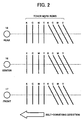
- Fig. 2 depicts an example of alignment toner mark rows formed on the conveyer belt 5.
- transverse lines and oblique lines K, C, M, and Y are formed on the conveyer belt 5.
- the transverse and oblique lines are detected by the sensors 17, 18, and 19 arranged in the main scan direction (direction perpendicular to the belt direction), to measure skew errors to a reference color (in this case, BK), resist errors in the sub-scan direction, resistor errors in the main scan direction, and magnification errors in the main scan direction. From the measurements, various shift lengths and quantities of correction are calculated.
- a CPU (described later) corrects the error components as follows.
- the skew errors are corrected by changing inclinations of mirrors (not shown) that reflect the laser beams of the respective colors in the exposing unit 11.
- a drive source to bias the mirrors a stepping motor is used.
- Correction of a resist error in the sub-scan direction is explained with reference to a timing chart, obtained when write timings in the sub-scan direction are corrected, as shown in Fig. 3.
- a correction resolution is set at 1 dot.
- An image region signal (write enable signal) in the sub-scan direction controls writing at a timing of a synchronization detection signal.
- the write enable signal may be made active one-synchronization signal ahead of the timing of the original write enable signal.
- Correction of a resist error in the main scan direction is explained with reference to a timing chart, obtained when write timing in the main scan direction is corrected, as shown in Fig. 4.
- a correction resolution is set at 1 dot.
- image write clocks clocks having accurately equal phases are obtained in each line by a trailing edge of a synchronization detection signal. An image is written in synchronization with the clock signal.
- the image write enable signal in the main scan direction is also formed in synchronization with the clock signal.
- the write enable signal may be made active one clock ahead of the timing of the original write enable signal.
- magnification when a magnification in the main scan direction shifts with respect to a reference color, the magnification can be changed by using a device which can change a frequency in fine steps, e.g., a clock generator which uses a VCO (Voltage Controlled Oscillator) or a PLL (Phase Locked Loop).
- a device which can change a frequency in fine steps, e.g., a clock generator which uses a VCO (Voltage Controlled Oscillator) or a PLL (Phase Locked Loop).
- VCO Voltage Controlled Oscillator
- PLL Phase Locked Loop
- the correction process is executed in the following cases:
- Fig. 5 depicts a functional block diagram of a process of stabilizing movement properties of the conveyer belt 5 shown in Fig. 1.
- a controller 21 Based on a detection result detected by a rotary encoder 20, a controller 21 calculates a speed deviation with respect to a target speed or a position deviation with respect to a target position to stabilize the conveyer belt.
- the calculated speed deviation or the position deviation is subjected to a PI control calculation to control the drive motor 22 serving as a drive source of the drive roller 7 that moves the conveyer belt 5.
- a feedback loop is constructed for the conveyer belt 5.
- a stepping motor is used as the drive motor 22 shown in Fig. 1.
- Fig. 6 illustrates a relationship between encoder output pulses string output according to movement of the conveyer belt and a control cycle timer that performs feedback control.
- Fig. 7 is a block diagram of functions of a control process performed in the image forming apparatus.
- a driven roller advance angle [rad] is calculated from the number of encoder output pulses at a leading edge of the control cycle timer shown in Fig. 6, and compared with a target angle displacement [rad].
- An obtained deviation [E(S)] is subjected to filter operation (low-pass filter operation) to cut a high-frequency component to obtain a value [E'(S)].
- a PI control calculation is performed to add [F(S)] and a reference frequency [F0(S)] to change a drive pulse frequency [F'(S)].
- the driven roller 8 and the conveyer belt 5 shown in Fig. 1 are designed such that the driven roller 8 does not slip on the conveyer belt 5, and an angular displacement and a moving distance of the conveyer belt 5 are equivalent to each other.
- Time (t[s]) of an interval between the leading edges of encoder output pulses shown in Fig. 6 is measured. It is decided whether the measured time falls within the range given by the equation (1) given below. If an average time interval of t is given by T0[S], it is understood that time (t) of a leading edge interval falls within a fluctuation range of 5% that can be considered in practical use. If the time t satisfies the following condition given by equation (1), there is no problem. 0.95T0 ⁇ t ⁇ 1.05T0
- the pulse interval t1 is determined as an error. Because a pulse interval t2 obtained when noise is superimposed on the encoder output does not fall within the range given by equation (1), the pulse interval t2 is determined as an error.
- Fig. 8 is a graph of a running sequence of the drive motor 22 (stepping motor) that performs full-color printing during image formation.
- a conveyer belt of the image forming apparatus is always in contact with the black photoconductor 9BK.
- the conveyer belt has a contacting/separating mechanism (not shown) that separates the conveyer belt from the C, M, and Y photoconductors 9C, 9M, and 9Y during printing for BK, and brings the conveyer belt into contact with the photoconductors 9C, 9M, and 9Y during full-color printing.
- the error decision is not performed during the through up, in which a process of activating and stopping the drive motor 22 (stepping motor) is performed, and during the transfer spacing.
- the error process is a process of switching a state in which the drive motor 22 (stepping motor) is subjected to feedback control based on the detection result detected by the rotary encoder 20 shown in Fig. 1 to a state in which the drive motor 22 (stepping motor) is rotated at a constant speed and a predetermined drive pulse frequency without being subjected to the feedback control.
- a color shift may be slightly deteriorated.
- some user may accept such an image.
- downtime of the image forming apparatus is produced. The downtime is not preferable for the position of a user.
- the error process may be a process of prohibiting image formation. Since some user desires to output only high-quality images being free from color shift, such a user is prohibited to form an image when the control error is decided.
- a process of stopping the feedback control of the drive motor 22 (stepping motor) and switching the drive motor (stepping motor) to the motor at a constant speed and a predetermined drive pulse frequency, and a process of prohibiting image formation can be selected to cope with the needs of various users.
- the error process is performed when a predetermined error occurs a predetermined number of times. In general, an error occurs even once, an erroneous image is output. The number of times for the error decision is set at 1.
- the error process is restored such that normal feedback control is performed by turning on/off the power supply of the image forming apparatus.
- noise superimposition may not be infrequently eliminated since, for example, noise superimposition or the like may occur due to an influence of another apparatus located around the image forming apparatus by accident, due to a situation of power supply, or the like.
- Fig. 9 is a program flowchart of a process procedure of an error decision process and an error process.
- step S1 It is decided whether any control error decision mask period selected from among through up, a settling & transfer contact period, a transfer spacing period, and through down shown in Fig. 8 is set (step S1).
- step S2 If any control error decision mask period is set (Yes at step S1), the process is shifted to RETURN. If any control error decision mask period is not set (No at step S1), it is determined whether an encoder pulse interval falls within the range given by 0.95T0 ⁇ t ⁇ 1.05T0 (step S2).
- step S3 If the encoder pulse interval falls within the range given by 0.95T0 ⁇ t ⁇ 1.05T0 (Yes at step S2), the process is shifted to RETURN. If the encoder pulse interval does not fall within the range given by 0.95T0 ⁇ t ⁇ 1.05T0 (NO in step S2), it is determined whether an image formation prohibition process is selected by a user as a process to be performed after the error decision (step S3).
- step S3 If the image formation prohibition process is selected (Yes at step S3), the image formation prohibition process is performed (step S4), and the process is shifted to RETURN. If the image formation prohibition process is not selected (No at step S3), the feedback control is stopped, the drive motor (stepping motor) is rotated at a predetermined speed (step S5), and the process is shifted to RETURN.
- step S2 the error decision is performed at the encoder pulse interval.
- the error decision can be performed at the drive pulse frequency of the drive motor 22 (stepping motor).
- Fig. 10 illustrates a configuration of various control units in the image forming apparatus.
- Each of the sensors 17, 18, and 19 includes a light-emitting element (not shown) and a light-receiving element (not shown) that are controlled by an emission amount controlling unit 23.
- the output side of the sensor is connected to an I/O port 30 through an AMP 24, a filter 25, an A/D converter 26, and an FIFO memory 28.
- the AMP 24 amplifies detection signals obtained by the sensors 17, 18, and 19.
- the amplified signals pass through the filter 25, and are converted by the A/D converter 26 from analog data into digital data.
- the sampling controlling unit 27 controls sampling of the data, and the FIFO memory 28 stores the sampling data.
- the sampling controlling unit 27, the FIFO memory 28, and the write control board 29 are connected to the I/O port 30.
- the rotary encoder 20 is also connected to the I/O port 30 to control an ON/OFF operation of the light-emitting unit.
- An output pulse is connected to the I/O port 30.
- the drive motor 22, which drives the drive roller that moves the conveyer belt, is also connected to the I/O port 30 to form a feedback control loop.
- the I/O port 30, a CPU 31, a ROM 32, and a RAM 33 are interconnected by a data bus 34 and an address bus 35.
- the ROM 32 various programs such as a program to calculate various positional shift lengths of toner images, and a program to perform feedback control are stored.
- the address bus 35 designates a ROM address, a RAM address, and various input/output devices.
- the CPU 31 monitors detection signals from the sensors 17, 18, and 19 at predetermined timings. Emission amounts of the light-emitting elements of the sensors 17, 18, and 19 are controlled by the emission amount control unit 23, to reliably detect toner images even though deterioration or the like of the conveyer belt 5 shown in Fig. 1 and the light-emitting elements of the sensors 17, 18, and 19 occurs, so that the output levels of light-emitting signals from the light-emitting elements are always constant.
- the CPU 31 performs setting for the write control board 29 based on quantities of correction calculated from detection results of position detection toner marks, to change a main resist and a sub-resist and to change an image frequency based on a magnification error.
- the write control board 29 includes devices, which can very finely set output frequencies, such as clock generators using, e.g., VCOs (Voltage Controlled Oscillators) for the respective colors including the reference color. Outputs from the devices are used as image clocks.
- the CPU 31 also controls a skew controlling stepping motor (not shown) in the exposing unit 11 shown in Fig. 1, based on the quantities of correction calculated from the detection results of the position detection toner marks.
- the CPU 31 measures pulses from an encoder output pulse to calculate a current position deviation to a target position, performs, a PI control calculation or the like to the position deviation, and outputs the obtained quantity of control to the drive motor 22 to stabilize the traveling of the conveyer belt.
- an error decision and an error process shown in the flow chart of Fig. 9 are performed.
- the image forming apparatus has the following configuration. That is, an intermediate transfer belt 36 is arranged as an intermediate transfer member in place of the conveyer belt 5 in the image forming apparatus according to the first embodiment. Images formed by image forming units 6Y, 6M, 6C, and 6BK are temporarily transferred onto the intermediate transfer belt 36, and the images on the intermediate transfer belt 36 are transferred onto a sheet of paper by a transfer belt 37 serving as a transferring unit.
- the transfer belt 37 also includes a function of conveying a sheet of paper to a fixing unit 16.
- a cleaning unit for the intermediate transfer belt 36 is indicated by reference numeral 38.
- a toner mark forming unit forms position detection toner marks of respective colors on the intermediate transfer belt 36.
- sensors 17, 18, and 19 are aligned in a main scan direction perpendicular to a rotating direction of the intermediate transfer belt 36.
- the direction of an arrow shown in Fig. 11 corresponding to the rotating direction of the intermediate transfer belt 36, and the direction perpendicular to the direction of the arrow corresponds to the main scan direction in which the sensors 17, 18, and 19 are aligned. All the position detection toner marks are formed at positions detected by the sensors 17, 18, and 19.
- the image forming apparatus including the transfer belt shown in Fig. 11 the positions of the position detection toner marks on the intermediate transfer belt 36 are detected, so that the positions of images formed on photoconductor drums 9Y, 9M, 9C, and 9BK can be corrected.
- the image forming apparatus includes a drive roller 7 and a driven roller 8 like the image forming apparatus shown in Fig. 1.
- a rotary encoder 20 is attached to the shaft of the driven roller 8 as in Fig. 1.
- a drive motor 22 is controlled based on detection results to constitute a feedback loop, and movement of the intermediate transfer belt 36 is stabilized.
- the embodiments are preferable embodiments of the present invention.
- Various modifications of the embodiments can be effected without departing from the spirit and scope of the invention.
- laser beams are applied as the exposing light sources in the embodiments.
- the light sources are not limited to the laser beams.
- an LED array or the like can also be used.
- detection of the speed and position of the belt may be performed by using not only the rotary encoder attached to the shaft of the driven roller, but also by a configuration that detects a scale or toner marks formed on the upper or lower surface of the belt.
- the stepping motor is used as the drive motor, the drive motor is not limited to the stepping motor, and a DC motor, an AC motor, or the like can also be used.
- PI control is applied as a control calculation performed by the controller, the control operation is not limited to the PI control, and P control, PID control, H ⁇ control, or the like can also be applied.
- An image forming apparatus performs a detected error decision in detection of a movable member and a control error decision in control of a driving unit on the basis of a moving distance or a moving speed of the movable member, and performs a predetermined error process when an error is determined, to prevent erroneous position control and erroneous speed control from being performed.
Landscapes
- Engineering & Computer Science (AREA)
- Microelectronics & Electronic Packaging (AREA)
- Physics & Mathematics (AREA)
- General Physics & Mathematics (AREA)
- Control Or Security For Electrophotography (AREA)
- Color Electrophotography (AREA)
- Control Of Electric Motors In General (AREA)
- Electrostatic Charge, Transfer And Separation In Electrography (AREA)
Applications Claiming Priority (2)
| Application Number | Priority Date | Filing Date | Title |
|---|---|---|---|
| JP2003304442A JP2005077469A (ja) | 2003-08-28 | 2003-08-28 | 画像形成装置 |
| JP2003304442 | 2003-08-28 |
Publications (3)
| Publication Number | Publication Date |
|---|---|
| EP1510876A2 true EP1510876A2 (de) | 2005-03-02 |
| EP1510876A3 EP1510876A3 (de) | 2005-09-21 |
| EP1510876B1 EP1510876B1 (de) | 2008-11-19 |
Family
ID=34101217
Family Applications (1)
| Application Number | Title | Priority Date | Filing Date |
|---|---|---|---|
| EP04020196A Expired - Lifetime EP1510876B1 (de) | 2003-08-28 | 2004-08-25 | Antriebsgeschwindigkeitsregelung für Bildformungsapparat |
Country Status (4)
| Country | Link |
|---|---|
| US (1) | US7581803B2 (de) |
| EP (1) | EP1510876B1 (de) |
| JP (1) | JP2005077469A (de) |
| DE (1) | DE602004017818D1 (de) |
Families Citing this family (14)
| Publication number | Priority date | Publication date | Assignee | Title |
|---|---|---|---|---|
| JP2005077469A (ja) | 2003-08-28 | 2005-03-24 | Ricoh Co Ltd | 画像形成装置 |
| JP2006178374A (ja) * | 2004-12-24 | 2006-07-06 | Brother Ind Ltd | 画像形成装置 |
| JP2006208639A (ja) * | 2005-01-27 | 2006-08-10 | Ricoh Co Ltd | 画像形成装置、プリンタ装置、ファクシミリ装置及び複写機 |
| JP4396559B2 (ja) * | 2005-03-24 | 2010-01-13 | 富士ゼロックス株式会社 | 液滴吐出装置 |
| JP2007041128A (ja) * | 2005-08-01 | 2007-02-15 | Ricoh Co Ltd | カラー画像形成装置 |
| JP2007125738A (ja) * | 2005-11-01 | 2007-05-24 | Ricoh Co Ltd | 光書込装置及び画像形成装置 |
| JP2007128006A (ja) * | 2005-11-07 | 2007-05-24 | Ricoh Co Ltd | 画像形成装置及び該画像形成装置の制御回路 |
| JP5057747B2 (ja) * | 2005-11-30 | 2012-10-24 | 株式会社リコー | 画像形成装置、画像形成動作補正方法、及び画像形成動作補正方法をコンピュータに実行させるためのプログラム |
| JP5495831B2 (ja) * | 2009-02-13 | 2014-05-21 | キヤノン株式会社 | 画像形成装置 |
| JP5240579B2 (ja) * | 2009-09-07 | 2013-07-17 | 株式会社リコー | 画像形成装置 |
| JP2013167678A (ja) * | 2012-02-14 | 2013-08-29 | Fuji Xerox Co Ltd | 無端状ベルト駆動装置およびそれを備える画像形成装置 |
| JP2014056188A (ja) | 2012-09-13 | 2014-03-27 | Ricoh Co Ltd | 画像形成装置、画像調整方法、プログラム、およびコンピュータ読み取り可能な記憶媒体 |
| JP6894687B2 (ja) * | 2016-10-11 | 2021-06-30 | キヤノン株式会社 | 画像処理システム、画像処理装置、制御方法、及び、プログラム |
| CN111169936B (zh) * | 2019-12-30 | 2022-02-18 | 无锡信捷电气股份有限公司 | 一种plc多工位控制的实现方法 |
Family Cites Families (33)
| Publication number | Priority date | Publication date | Assignee | Title |
|---|---|---|---|---|
| US4275968A (en) * | 1979-04-30 | 1981-06-30 | Ibm Corporation | System for controlling and sequencing a printer |
| US4873541A (en) * | 1987-05-28 | 1989-10-10 | Canon Kabushiki Kaisha | Image forming apparatus |
| JPH05257357A (ja) * | 1992-01-17 | 1993-10-08 | Sharp Corp | 電子写真装置 |
| US5621221A (en) | 1993-12-22 | 1997-04-15 | Ricoh Company, Ltd. | Toner end detection device and method |
| US5899597A (en) | 1993-12-22 | 1999-05-04 | Ricoh Company Ltd. | Toner cartridge with an external reflector for a developer apparatus capable of optically end-detecting |
| US5502544A (en) * | 1994-09-15 | 1996-03-26 | Xerox Corporation | Parameter based digital servo controller |
| JP3514398B2 (ja) | 1994-12-07 | 2004-03-31 | 株式会社リコー | 画像形成装置 |
| US5963240A (en) | 1996-02-02 | 1999-10-05 | Ricoh Company, Ltd. | Deflecting mirror adjusting device for an image forming apparatus |
| JP3527352B2 (ja) | 1996-02-26 | 2004-05-17 | 株式会社リコー | カラ−画像形成装置 |
| JPH1031027A (ja) | 1996-07-15 | 1998-02-03 | Ricoh Co Ltd | 回転速度検知装置 |
| JPH10198110A (ja) | 1996-11-18 | 1998-07-31 | Ricoh Co Ltd | カラー画像形成方法 |
| US5875380A (en) | 1997-02-18 | 1999-02-23 | Ricoh Company, Ltd. | Image forming apparatus eliminating influence of fluctuation in speed of a conveying belt to correction of offset in color registration |
| JPH1124507A (ja) | 1997-07-07 | 1999-01-29 | Ricoh Co Ltd | 画像形成装置 |
| US6201944B1 (en) * | 1997-08-12 | 2001-03-13 | Minolta Co., Ltd. | Tandem-type image forming apparatus operating in color mode and monochrome mode |
| JPH11146675A (ja) * | 1997-11-07 | 1999-05-28 | Canon Inc | モータ制御装置及び画像形成装置 |
| JP2000318221A (ja) | 1999-05-14 | 2000-11-21 | Ricoh Co Ltd | 画像形成装置 |
| JP4143947B2 (ja) * | 1999-07-02 | 2008-09-03 | リコープリンティングシステムズ株式会社 | 電子写真装置 |
| US6302514B1 (en) * | 1999-09-03 | 2001-10-16 | Lexmark International, Inc. | Method and apparatus for automatically correcting the fire timing of a printhead carrier due to linear encoder velocity errors |
| JP2001096873A (ja) * | 1999-09-29 | 2001-04-10 | Canon Inc | 画像形成装置 |
| JP4149627B2 (ja) | 1999-10-18 | 2008-09-10 | 株式会社リコー | カラー画像形成装置 |
| JP2001166553A (ja) | 1999-12-13 | 2001-06-22 | Ricoh Co Ltd | カラー画像形成装置 |
| JP3772628B2 (ja) * | 2000-02-29 | 2006-05-10 | コニカミノルタビジネステクノロジーズ株式会社 | 画像処理装置 |
| JP4447729B2 (ja) * | 2000-04-13 | 2010-04-07 | キヤノン株式会社 | 画像形成装置 |
| JP2002055292A (ja) | 2000-08-11 | 2002-02-20 | Ricoh Co Ltd | 光ビーム走査装置 |
| US6573918B2 (en) | 2000-08-22 | 2003-06-03 | Ricoh Company, Ltd. | Image forming apparatus having a plurality of image data interfaces |
| JP4042127B2 (ja) | 2001-01-10 | 2008-02-06 | 株式会社リコー | カラー画像形成装置 |
| US20020104393A1 (en) * | 2001-02-07 | 2002-08-08 | Van Es J. R. | Variable moment vibrator |
| JP2003084530A (ja) | 2001-09-14 | 2003-03-19 | Ricoh Co Ltd | カラー画像形成装置 |
| JP3640629B2 (ja) | 2001-09-21 | 2005-04-20 | 株式会社リコー | カラー画像形成装置 |
| US6805425B2 (en) * | 2002-01-11 | 2004-10-19 | Brother Kogyo Kabushiki Kaisha | Image forming device |
| JP3945326B2 (ja) * | 2002-07-09 | 2007-07-18 | ブラザー工業株式会社 | 搬送体清掃装置及びそれを使用したインクジェット記録装置 |
| DE10318997A1 (de) * | 2003-04-25 | 2005-01-27 | Nexpress Solutions Llc | Verfahren und Steuerungseinrichtung zum Vermeiden von Registerfehlern |
| JP2005077469A (ja) | 2003-08-28 | 2005-03-24 | Ricoh Co Ltd | 画像形成装置 |
-
2003
- 2003-08-28 JP JP2003304442A patent/JP2005077469A/ja not_active Withdrawn
-
2004
- 2004-08-25 EP EP04020196A patent/EP1510876B1/de not_active Expired - Lifetime
- 2004-08-25 DE DE602004017818T patent/DE602004017818D1/de not_active Expired - Lifetime
- 2004-08-27 US US10/927,162 patent/US7581803B2/en active Active
Also Published As
| Publication number | Publication date |
|---|---|
| EP1510876A3 (de) | 2005-09-21 |
| EP1510876B1 (de) | 2008-11-19 |
| JP2005077469A (ja) | 2005-03-24 |
| US7581803B2 (en) | 2009-09-01 |
| US20050088505A1 (en) | 2005-04-28 |
| DE602004017818D1 (de) | 2009-01-02 |
Similar Documents
| Publication | Publication Date | Title |
|---|---|---|
| JP3932715B2 (ja) | カラー画像形成装置 | |
| EP1931125B1 (de) | Bilderzeugungsvorrichtung | |
| US6336024B1 (en) | Image forming apparatus capable of reducing color misregistration | |
| US7389075B2 (en) | Image forming apparatus, program and positional error correction method | |
| US7581803B2 (en) | Image forming apparatus, method and computer readable medium for executing predetermined error processes in response to a moveable member error | |
| JP4710702B2 (ja) | カラー画像形成装置 | |
| JP4359538B2 (ja) | カラー画像形成装置、カラー画像形成方法、カラー画像形成プログラム、及び記録媒体 | |
| JP2007148134A (ja) | 画質調整装置、画像形成装置及び画質調整方法 | |
| JP2013238673A (ja) | 画像形成装置 | |
| US7660542B2 (en) | Image forming method and image forming apparatus for forming an image on a surface of a transfer member | |
| JP2002014507A (ja) | 画像形成装置 | |
| JP4869692B2 (ja) | 画像形成装置、色ずれ補正方法および色ずれ補正プログラム | |
| JP5006086B2 (ja) | 画像形成装置 | |
| JP2014178385A (ja) | 画像形成装置、画像形成方法、及びプログラム | |
| JP4835706B2 (ja) | 画像形成装置 | |
| JP2004069801A (ja) | カラー画像形成装置 | |
| JP4323757B2 (ja) | カラー画像形成装置 | |
| JP2006047934A (ja) | カラー画像形成装置、その駆動制御方法及び駆動制御プログラム | |
| JP2003091126A (ja) | 画像形成装置 | |
| JP4820733B2 (ja) | 画像形成装置 | |
| JP2016095390A (ja) | 画像形成装置 | |
| JP2017032823A (ja) | 画像形成装置 | |
| JP2005215482A (ja) | 画像形成装置 | |
| JP2007298868A (ja) | 画像形成装置及び画像形成方法 | |
| JP2005091901A (ja) | カラー画像形成装置 |
Legal Events
| Date | Code | Title | Description |
|---|---|---|---|
| PUAI | Public reference made under article 153(3) epc to a published international application that has entered the european phase |
Free format text: ORIGINAL CODE: 0009012 |
|
| AK | Designated contracting states |
Kind code of ref document: A2 Designated state(s): AT BE BG CH CY CZ DE DK EE ES FI FR GB GR HU IE IT LI LU MC NL PL PT RO SE SI SK TR |
|
| AX | Request for extension of the european patent |
Extension state: AL HR LT LV MK |
|
| PUAL | Search report despatched |
Free format text: ORIGINAL CODE: 0009013 |
|
| AK | Designated contracting states |
Kind code of ref document: A3 Designated state(s): AT BE BG CH CY CZ DE DK EE ES FI FR GB GR HU IE IT LI LU MC NL PL PT RO SE SI SK TR |
|
| AX | Request for extension of the european patent |
Extension state: AL HR LT LV MK |
|
| 17P | Request for examination filed |
Effective date: 20050914 |
|
| AKX | Designation fees paid |
Designated state(s): DE ES FR GB IT NL |
|
| 17Q | First examination report despatched |
Effective date: 20061214 |
|
| GRAP | Despatch of communication of intention to grant a patent |
Free format text: ORIGINAL CODE: EPIDOSNIGR1 |
|
| GRAS | Grant fee paid |
Free format text: ORIGINAL CODE: EPIDOSNIGR3 |
|
| GRAA | (expected) grant |
Free format text: ORIGINAL CODE: 0009210 |
|
| AK | Designated contracting states |
Kind code of ref document: B1 Designated state(s): DE ES FR GB IT NL |
|
| REG | Reference to a national code |
Ref country code: GB Ref legal event code: FG4D |
|
| REF | Corresponds to: |
Ref document number: 602004017818 Country of ref document: DE Date of ref document: 20090102 Kind code of ref document: P |
|
| PG25 | Lapsed in a contracting state [announced via postgrant information from national office to epo] |
Ref country code: ES Free format text: LAPSE BECAUSE OF FAILURE TO SUBMIT A TRANSLATION OF THE DESCRIPTION OR TO PAY THE FEE WITHIN THE PRESCRIBED TIME-LIMIT Effective date: 20090301 |
|
| NLV1 | Nl: lapsed or annulled due to failure to fulfill the requirements of art. 29p and 29m of the patents act | ||
| PG25 | Lapsed in a contracting state [announced via postgrant information from national office to epo] |
Ref country code: NL Free format text: LAPSE BECAUSE OF FAILURE TO SUBMIT A TRANSLATION OF THE DESCRIPTION OR TO PAY THE FEE WITHIN THE PRESCRIBED TIME-LIMIT Effective date: 20081119 |
|
| PLBE | No opposition filed within time limit |
Free format text: ORIGINAL CODE: 0009261 |
|
| STAA | Information on the status of an ep patent application or granted ep patent |
Free format text: STATUS: NO OPPOSITION FILED WITHIN TIME LIMIT |
|
| 26N | No opposition filed |
Effective date: 20090820 |
|
| PG25 | Lapsed in a contracting state [announced via postgrant information from national office to epo] |
Ref country code: IT Free format text: LAPSE BECAUSE OF FAILURE TO SUBMIT A TRANSLATION OF THE DESCRIPTION OR TO PAY THE FEE WITHIN THE PRESCRIBED TIME-LIMIT Effective date: 20081119 |
|
| PGFP | Annual fee paid to national office [announced via postgrant information from national office to epo] |
Ref country code: GB Payment date: 20120821 Year of fee payment: 9 |
|
| PGFP | Annual fee paid to national office [announced via postgrant information from national office to epo] |
Ref country code: FR Payment date: 20120906 Year of fee payment: 9 |
|
| GBPC | Gb: european patent ceased through non-payment of renewal fee |
Effective date: 20130825 |
|
| REG | Reference to a national code |
Ref country code: FR Ref legal event code: ST Effective date: 20140430 |
|
| PG25 | Lapsed in a contracting state [announced via postgrant information from national office to epo] |
Ref country code: GB Free format text: LAPSE BECAUSE OF NON-PAYMENT OF DUE FEES Effective date: 20130825 |
|
| PG25 | Lapsed in a contracting state [announced via postgrant information from national office to epo] |
Ref country code: FR Free format text: LAPSE BECAUSE OF NON-PAYMENT OF DUE FEES Effective date: 20130902 |
|
| PGFP | Annual fee paid to national office [announced via postgrant information from national office to epo] |
Ref country code: DE Payment date: 20170822 Year of fee payment: 14 |
|
| REG | Reference to a national code |
Ref country code: DE Ref legal event code: R119 Ref document number: 602004017818 Country of ref document: DE |
|
| PG25 | Lapsed in a contracting state [announced via postgrant information from national office to epo] |
Ref country code: DE Free format text: LAPSE BECAUSE OF NON-PAYMENT OF DUE FEES Effective date: 20190301 |