EP1504330B1 - Procede et systeme pour obtenir des donnees de positionnement - Google Patents
Procede et systeme pour obtenir des donnees de positionnement Download PDFInfo
- Publication number
- EP1504330B1 EP1504330B1 EP03715318A EP03715318A EP1504330B1 EP 1504330 B1 EP1504330 B1 EP 1504330B1 EP 03715318 A EP03715318 A EP 03715318A EP 03715318 A EP03715318 A EP 03715318A EP 1504330 B1 EP1504330 B1 EP 1504330B1
- Authority
- EP
- European Patent Office
- Prior art keywords
- position detection
- detection system
- waveform
- positional element
- signals
- Prior art date
- Legal status (The legal status is an assumption and is not a legal conclusion. Google has not performed a legal analysis and makes no representation as to the accuracy of the status listed.)
- Expired - Lifetime
Links
- 238000000034 method Methods 0.000 title claims description 17
- 238000001514 detection method Methods 0.000 claims description 138
- 238000005070 sampling Methods 0.000 claims description 36
- 230000033001 locomotion Effects 0.000 claims description 23
- 238000007476 Maximum Likelihood Methods 0.000 claims description 20
- 238000004891 communication Methods 0.000 claims description 14
- 238000012795 verification Methods 0.000 claims description 12
- 230000001413 cellular effect Effects 0.000 claims description 11
- 238000006243 chemical reaction Methods 0.000 claims description 10
- 230000005236 sound signal Effects 0.000 claims description 8
- 238000009434 installation Methods 0.000 claims description 6
- 238000004364 calculation method Methods 0.000 claims description 5
- 238000005314 correlation function Methods 0.000 claims description 5
- 230000011664 signaling Effects 0.000 claims description 5
- 239000013598 vector Substances 0.000 claims description 5
- 238000013519 translation Methods 0.000 claims description 4
- 230000004044 response Effects 0.000 claims description 3
- 238000001228 spectrum Methods 0.000 claims description 3
- 238000003491 array Methods 0.000 claims description 2
- 230000008439 repair process Effects 0.000 claims description 2
- 230000001934 delay Effects 0.000 abstract description 5
- 238000010586 diagram Methods 0.000 description 25
- 238000005516 engineering process Methods 0.000 description 24
- 241001422033 Thestylus Species 0.000 description 15
- 241000699666 Mus <mouse, genus> Species 0.000 description 10
- 230000006870 function Effects 0.000 description 10
- 238000012546 transfer Methods 0.000 description 9
- 238000012545 processing Methods 0.000 description 8
- 239000000463 material Substances 0.000 description 7
- 229920001690 polydopamine Polymers 0.000 description 7
- 230000005540 biological transmission Effects 0.000 description 5
- 230000002452 interceptive effect Effects 0.000 description 5
- 238000004519 manufacturing process Methods 0.000 description 5
- 238000002604 ultrasonography Methods 0.000 description 5
- 230000008859 change Effects 0.000 description 4
- 230000003993 interaction Effects 0.000 description 4
- 238000005259 measurement Methods 0.000 description 4
- 239000000047 product Substances 0.000 description 4
- 230000001360 synchronised effect Effects 0.000 description 4
- 230000008901 benefit Effects 0.000 description 3
- 238000000576 coating method Methods 0.000 description 3
- 238000001914 filtration Methods 0.000 description 3
- 238000013178 mathematical model Methods 0.000 description 3
- XEEYBQQBJWHFJM-UHFFFAOYSA-N Iron Chemical group [Fe] XEEYBQQBJWHFJM-UHFFFAOYSA-N 0.000 description 2
- 230000003321 amplification Effects 0.000 description 2
- 230000006399 behavior Effects 0.000 description 2
- 239000011248 coating agent Substances 0.000 description 2
- 238000010276 construction Methods 0.000 description 2
- 239000013078 crystal Substances 0.000 description 2
- 238000013461 design Methods 0.000 description 2
- 238000010348 incorporation Methods 0.000 description 2
- 230000010354 integration Effects 0.000 description 2
- 239000003550 marker Substances 0.000 description 2
- 238000003199 nucleic acid amplification method Methods 0.000 description 2
- 230000003287 optical effect Effects 0.000 description 2
- 238000007639 printing Methods 0.000 description 2
- 241000699670 Mus sp. Species 0.000 description 1
- 108010076504 Protein Sorting Signals Proteins 0.000 description 1
- 230000001133 acceleration Effects 0.000 description 1
- 230000005534 acoustic noise Effects 0.000 description 1
- 230000003139 buffering effect Effects 0.000 description 1
- 230000015556 catabolic process Effects 0.000 description 1
- 239000007795 chemical reaction product Substances 0.000 description 1
- 239000012141 concentrate Substances 0.000 description 1
- 239000004020 conductor Substances 0.000 description 1
- 125000004122 cyclic group Chemical group 0.000 description 1
- 238000006731 degradation reaction Methods 0.000 description 1
- 230000000694 effects Effects 0.000 description 1
- 230000005672 electromagnetic field Effects 0.000 description 1
- 238000004880 explosion Methods 0.000 description 1
- 238000013213 extrapolation Methods 0.000 description 1
- 239000012467 final product Substances 0.000 description 1
- 230000006698 induction Effects 0.000 description 1
- 230000001939 inductive effect Effects 0.000 description 1
- 230000007246 mechanism Effects 0.000 description 1
- 238000012806 monitoring device Methods 0.000 description 1
- 238000005457 optimization Methods 0.000 description 1
- 229920000729 poly(L-lysine) polymer Polymers 0.000 description 1
- 238000007781 pre-processing Methods 0.000 description 1
- 230000008569 process Effects 0.000 description 1
- 230000002207 retinal effect Effects 0.000 description 1
- 230000003595 spectral effect Effects 0.000 description 1
Images


Classifications
-
- B—PERFORMING OPERATIONS; TRANSPORTING
- B25—HAND TOOLS; PORTABLE POWER-DRIVEN TOOLS; MANIPULATORS
- B25J—MANIPULATORS; CHAMBERS PROVIDED WITH MANIPULATION DEVICES
- B25J9/00—Programme-controlled manipulators
- B25J9/16—Programme controls
- B25J9/1694—Programme controls characterised by use of sensors other than normal servo-feedback from position, speed or acceleration sensors, perception control, multi-sensor controlled systems, sensor fusion
-
- G—PHYSICS
- G06—COMPUTING; CALCULATING OR COUNTING
- G06F—ELECTRIC DIGITAL DATA PROCESSING
- G06F3/00—Input arrangements for transferring data to be processed into a form capable of being handled by the computer; Output arrangements for transferring data from processing unit to output unit, e.g. interface arrangements
- G06F3/01—Input arrangements or combined input and output arrangements for interaction between user and computer
- G06F3/011—Arrangements for interaction with the human body, e.g. for user immersion in virtual reality
-
- G—PHYSICS
- G06—COMPUTING; CALCULATING OR COUNTING
- G06F—ELECTRIC DIGITAL DATA PROCESSING
- G06F17/00—Digital computing or data processing equipment or methods, specially adapted for specific functions
-
- B—PERFORMING OPERATIONS; TRANSPORTING
- B25—HAND TOOLS; PORTABLE POWER-DRIVEN TOOLS; MANIPULATORS
- B25J—MANIPULATORS; CHAMBERS PROVIDED WITH MANIPULATION DEVICES
- B25J13/00—Controls for manipulators
- B25J13/02—Hand grip control means
-
- B—PERFORMING OPERATIONS; TRANSPORTING
- B25—HAND TOOLS; PORTABLE POWER-DRIVEN TOOLS; MANIPULATORS
- B25J—MANIPULATORS; CHAMBERS PROVIDED WITH MANIPULATION DEVICES
- B25J13/00—Controls for manipulators
- B25J13/06—Control stands, e.g. consoles, switchboards
-
- B—PERFORMING OPERATIONS; TRANSPORTING
- B25—HAND TOOLS; PORTABLE POWER-DRIVEN TOOLS; MANIPULATORS
- B25J—MANIPULATORS; CHAMBERS PROVIDED WITH MANIPULATION DEVICES
- B25J13/00—Controls for manipulators
- B25J13/06—Control stands, e.g. consoles, switchboards
- B25J13/065—Control stands, e.g. consoles, switchboards comprising joy-sticks
-
- B—PERFORMING OPERATIONS; TRANSPORTING
- B25—HAND TOOLS; PORTABLE POWER-DRIVEN TOOLS; MANIPULATORS
- B25J—MANIPULATORS; CHAMBERS PROVIDED WITH MANIPULATION DEVICES
- B25J19/00—Accessories fitted to manipulators, e.g. for monitoring, for viewing; Safety devices combined with or specially adapted for use in connection with manipulators
- B25J19/02—Sensing devices
- B25J19/026—Acoustical sensing devices
-
- B—PERFORMING OPERATIONS; TRANSPORTING
- B25—HAND TOOLS; PORTABLE POWER-DRIVEN TOOLS; MANIPULATORS
- B25J—MANIPULATORS; CHAMBERS PROVIDED WITH MANIPULATION DEVICES
- B25J9/00—Programme-controlled manipulators
- B25J9/16—Programme controls
- B25J9/1656—Programme controls characterised by programming, planning systems for manipulators
- B25J9/1664—Programme controls characterised by programming, planning systems for manipulators characterised by motion, path, trajectory planning
-
- G—PHYSICS
- G06—COMPUTING; CALCULATING OR COUNTING
- G06F—ELECTRIC DIGITAL DATA PROCESSING
- G06F3/00—Input arrangements for transferring data to be processed into a form capable of being handled by the computer; Output arrangements for transferring data from processing unit to output unit, e.g. interface arrangements
- G06F3/01—Input arrangements or combined input and output arrangements for interaction between user and computer
- G06F3/011—Arrangements for interaction with the human body, e.g. for user immersion in virtual reality
- G06F3/014—Hand-worn input/output arrangements, e.g. data gloves
-
- G—PHYSICS
- G06—COMPUTING; CALCULATING OR COUNTING
- G06F—ELECTRIC DIGITAL DATA PROCESSING
- G06F3/00—Input arrangements for transferring data to be processed into a form capable of being handled by the computer; Output arrangements for transferring data from processing unit to output unit, e.g. interface arrangements
- G06F3/01—Input arrangements or combined input and output arrangements for interaction between user and computer
- G06F3/03—Arrangements for converting the position or the displacement of a member into a coded form
- G06F3/0304—Detection arrangements using opto-electronic means
-
- G—PHYSICS
- G06—COMPUTING; CALCULATING OR COUNTING
- G06F—ELECTRIC DIGITAL DATA PROCESSING
- G06F3/00—Input arrangements for transferring data to be processed into a form capable of being handled by the computer; Output arrangements for transferring data from processing unit to output unit, e.g. interface arrangements
- G06F3/01—Input arrangements or combined input and output arrangements for interaction between user and computer
- G06F3/03—Arrangements for converting the position or the displacement of a member into a coded form
- G06F3/033—Pointing devices displaced or positioned by the user, e.g. mice, trackballs, pens or joysticks; Accessories therefor
- G06F3/0346—Pointing devices displaced or positioned by the user, e.g. mice, trackballs, pens or joysticks; Accessories therefor with detection of the device orientation or free movement in a 3D space, e.g. 3D mice, 6-DOF [six degrees of freedom] pointers using gyroscopes, accelerometers or tilt-sensors
-
- G—PHYSICS
- G06—COMPUTING; CALCULATING OR COUNTING
- G06F—ELECTRIC DIGITAL DATA PROCESSING
- G06F3/00—Input arrangements for transferring data to be processed into a form capable of being handled by the computer; Output arrangements for transferring data from processing unit to output unit, e.g. interface arrangements
- G06F3/01—Input arrangements or combined input and output arrangements for interaction between user and computer
- G06F3/03—Arrangements for converting the position or the displacement of a member into a coded form
- G06F3/033—Pointing devices displaced or positioned by the user, e.g. mice, trackballs, pens or joysticks; Accessories therefor
- G06F3/0354—Pointing devices displaced or positioned by the user, e.g. mice, trackballs, pens or joysticks; Accessories therefor with detection of 2D relative movements between the device, or an operating part thereof, and a plane or surface, e.g. 2D mice, trackballs, pens or pucks
- G06F3/03545—Pens or stylus
-
- G—PHYSICS
- G06—COMPUTING; CALCULATING OR COUNTING
- G06F—ELECTRIC DIGITAL DATA PROCESSING
- G06F3/00—Input arrangements for transferring data to be processed into a form capable of being handled by the computer; Output arrangements for transferring data from processing unit to output unit, e.g. interface arrangements
- G06F3/01—Input arrangements or combined input and output arrangements for interaction between user and computer
- G06F3/03—Arrangements for converting the position or the displacement of a member into a coded form
- G06F3/041—Digitisers, e.g. for touch screens or touch pads, characterised by the transducing means
- G06F3/043—Digitisers, e.g. for touch screens or touch pads, characterised by the transducing means using propagating acoustic waves
-
- G—PHYSICS
- G06—COMPUTING; CALCULATING OR COUNTING
- G06F—ELECTRIC DIGITAL DATA PROCESSING
- G06F3/00—Input arrangements for transferring data to be processed into a form capable of being handled by the computer; Output arrangements for transferring data from processing unit to output unit, e.g. interface arrangements
- G06F3/01—Input arrangements or combined input and output arrangements for interaction between user and computer
- G06F3/03—Arrangements for converting the position or the displacement of a member into a coded form
- G06F3/041—Digitisers, e.g. for touch screens or touch pads, characterised by the transducing means
- G06F3/046—Digitisers, e.g. for touch screens or touch pads, characterised by the transducing means by electromagnetic means
-
- G—PHYSICS
- G06—COMPUTING; CALCULATING OR COUNTING
- G06V—IMAGE OR VIDEO RECOGNITION OR UNDERSTANDING
- G06V30/00—Character recognition; Recognising digital ink; Document-oriented image-based pattern recognition
- G06V30/10—Character recognition
- G06V30/22—Character recognition characterised by the type of writing
- G06V30/228—Character recognition characterised by the type of writing of three-dimensional handwriting, e.g. writing in the air
-
- Y—GENERAL TAGGING OF NEW TECHNOLOGICAL DEVELOPMENTS; GENERAL TAGGING OF CROSS-SECTIONAL TECHNOLOGIES SPANNING OVER SEVERAL SECTIONS OF THE IPC; TECHNICAL SUBJECTS COVERED BY FORMER USPC CROSS-REFERENCE ART COLLECTIONS [XRACs] AND DIGESTS
- Y10—TECHNICAL SUBJECTS COVERED BY FORMER USPC
- Y10S—TECHNICAL SUBJECTS COVERED BY FORMER USPC CROSS-REFERENCE ART COLLECTIONS [XRACs] AND DIGESTS
- Y10S901/00—Robots
- Y10S901/02—Arm motion controller
- Y10S901/06—Communication with another machine
- Y10S901/08—Robot
-
- Y—GENERAL TAGGING OF NEW TECHNOLOGICAL DEVELOPMENTS; GENERAL TAGGING OF CROSS-SECTIONAL TECHNOLOGIES SPANNING OVER SEVERAL SECTIONS OF THE IPC; TECHNICAL SUBJECTS COVERED BY FORMER USPC CROSS-REFERENCE ART COLLECTIONS [XRACs] AND DIGESTS
- Y10—TECHNICAL SUBJECTS COVERED BY FORMER USPC
- Y10S—TECHNICAL SUBJECTS COVERED BY FORMER USPC CROSS-REFERENCE ART COLLECTIONS [XRACs] AND DIGESTS
- Y10S901/00—Robots
- Y10S901/02—Arm motion controller
- Y10S901/09—Closed loop, sensor feedback controls arm movement
Definitions
- the present invention relates to a method and system for obtaining two or three-dimensional co-ordinate data in space and, more particularly, but not exclusively to a positional element and supporting hardware and software for obtaining such co-ordinate information.
- one unit is able to determine the position, typically in relation to itself, of another unit.
- the field of small space positioning that is positioning within spaces of a few meters or less, includes a number of fields, principally pointing devices for computer interaction, and robotics and machine control, but also including toys, inventory control and other fields.
- Certain applications may require 2D solutions, others may require 3D solutions. Again certain applications such as pointing devices may require only one-way communication, whereas say robotics may require two-way communication.
- Digital pens are pointing devices used for electronic detection of handwriting or hand drawing, or for general pointing.
- the digital pens generally use technologies such as acoustics, IR and light.
- Other versions use accelerometers that sense accelerations and transmit the data to a base station.
- Another version is a camera that analyzes small printing codes on special paper to determine its position.
- Other pens use electromagnetic (including passive & active), and other technologies for their operation.
- Some of the digital pens are an autonomous unit, meaning the pen works independently, providing its own fully processed co-ordinates as an output, and such is typical of optical and digital camera based units. Others, especially acoustic and electromagnetic devices, require a receiving or sensing unit.
- Digital Pens are widely used with PC's, laptops, PDA's, cellular telephones, electronic books, and the like.
- the interactive whiteboard is a whiteboard that captures written data from the board into an associated computer.
- One of the common technologies in this field is acoustic positioning: a marker is placed in a sleeve that transmits beacon signals which are picked up and analyzed by a dedicated device also placed near the whiteboard. In some cases an IR or electromagnetic signal is transmitted along with the acoustic beacon to for better accuracy and for simplicity.
- Another common technology is electromagnetic: the above mentioned marker sleeve transmits an electromagnetic field which is picked up by special loops on the back of the whiteboard.
- Resistive technology is also used.
- the surface of the whiteboard is coated with resistive material.
- Pressure is applied to the coating, and the pressure causes a local change in the resistive properties of the board. From the changes, the controller is able to obtain an x, y position from the applied pressure.
- Capacitive technology which is similar to the resistive, can also be used. Again, pressure is used, this time to change the capacitive properties of the board. Then, the controller is able to obtain the x, y position
- Touch screens generally comprise sensors embedded within or near a computer screen in order to receive input from the screen. Some technologies include coating the screen with special material that can sense physical contact, the material being any of resistive, capacitive and SAW material. Other technologies include embedding of sensors around the screen. The sensors may be IR, acoustic, SAW and others.
- a 3D mouse uses electromagnetic or ultrasonic positioning techniques to indicate its position in 3-D space to a monitoring device.
- the cordless mice in use today use BlueTooth and similar radio and IR transmitters for wireless connectivity.
- the radio or IR only takes care of the wireless connectivity, that is the signaling issue.
- Positioning generally involves a movement tracker in the mouse itself, which may be optically based. Simple movement tracking gives a 2D solution.
- 3D solutions can be produced, for example using either of the following:
- the PC tablet uses a digital pen or stylus.
- the stylus enables interactions including writing directly on a graphic tablet, pc tablet, pc screen, pda screen, cell-phone screen and on any other computer enabled surface, screen or tablet.
- Available solutions work with passive or active electromagnetic or acoustic technologies.
- the electromagnetic solution needs antenna loops on the back of the board
- the pen with the camera needs special digitized paper
- the touch-screens need special coatings.
- the need for sensors adds both to the cost of the final product, and furthermore provides an unnatural restriction on use in that it does not allow the user to use arbitrary planes, such as a cluttered desk surface, as a working platform.
- Bluetooth is nevertheless restricted to eight simultaneous users.
- Some of the technologies are limited to two-dimensional location. But even those that can manage a third dimension do not currently provide accurate information of the third dimension. For example a stylus based on electromagnetic detection can be detected when hovering above a screen, but it is not possible to tell accurately how high it is. The detector simply determines that it is present.
- Robotics and Machine control is a field in which the use of position sensors is inherent to the control of moving elements.
- PCB assembly machines perform placement of electronic components on a 2-dimentional printed circuit board.
- CNC machines perform cut and drill tasks which need high position resolution.
- Automobile assembly lines use automatic drillers which drill the body of the car using high spacial accuracy.
- Fax and printer machines have accurate position sensors for scanning, printing, paper orientation etc.
- the robotics products include freely moving robots for different applications.
- the applications include lawn mowers, pool cleaners, spy and bomb disposal robots with cameras and remote control and many more.
- Such robots typically use their own sensing together with pre-programming to find their way around in their surrounding environment.
- Possible new applications include an autonomous vacuum cleaner.
- One or more vacuum cleaners may roam automatically around the premises, vacuuming dirt and transferring the dirt to either fixed location units or roaming units.
- the unit that vacuums may autonomously locate the receiving unit to which it delivers the dirt and dock therewith in order to deliver the dirt.
- the preamble of claim 1 is based on the document NONAKA H. ET AL: "Ultrasonic position measurement and its applications to human interface” INSTRUMENTATION AND MEASUREMENT TECHNOLOGY CONFERENCE, 1994. IMTC/94. CONFERENCE PROCEEDINGS. 10TH ANNIVERSARY. ADVANCED TECHNOLOGIES IN I & M., 1994 IEEE HAMAMATSU, JAPAN 10-12 MAY 1994, NEW YORK, NY, USA, IEEE, 10 May 1994 (1994-05-10), pages 753-756, XP010121966, ISBN: 0-7803-1880-3.
- a position detection system for use in association with computing applications, the system comprises a positional element for attaining position and an emitter for emitting an unmodulated continuous ultrasonic wave which is decodable to determine said position, the system further comprises a detector arrangement for detecting said waveform and for determining said position.
- a position detection system as defined in claim 1.
- the detector arrangement is operable to emit the waveform decodable to fix the position, such that the waveform is decodable at low sampling rate.
- the waveform comprises a periodicity.
- the outputting comprises providing the waveform decodable at low sampling rate to at least one analog input of a computing device for the computation.
- the outputting comprises providing the waveform to at least two analog inputs of the computing device.
- a preferred embodiment comprises a plurality of positioning elements, and wherein the detector arrangement is configured to supply respective waveforms as separate channels for the outputting.
- a preferred embodiment comprises a plurality of detector arrangements to give greater detection precision.
- the separate channels are time multiplexed or frequency multiplexed.
- each positioning element further comprises a modulator for modulating the continuous wave.
- the modulator is a frequency modulator.
- each positioning element is provided with a frequency hopping sequence to allow simultaneous use of the plurality of positioning elements.
- each the frequency hopping sequence is a different pseudo-random sequence.
- the modulator is an amplitude modulator.
- the modulator is operable to modulate data additional to positional data to the waveform.
- each positioning element comprises a unique identifier.
- the continuous wave is modulated.
- the continuous wave is modulated using spread spectrum.
- the continuous wave is modulated using time division modulation.
- the positional element comprises a biometric sensor.
- the detection arrangement comprises a plurality of receivers, to provide multi-dimensional detection of the position.
- the outputting comprises providing the waveform decodable at low sampling rate to an analog input of a computing device for the computation and further is able to multiplex signals of the waveform from each one of the plurality of receivers for the inputting to the analog input.
- a preferred embodiment makes use of a demultiplexing capability of the computing device to demultiplex the signals received at the analog input.
- the positional element further comprises a second emitter for emitting a signal additional to the continuous waveform and having a different speed therefrom, therewith to obtain data indicative of a distance between the positional element and detectors of the detector arrangement from a time delay between the continuous waveform and the additional signal.
- a second emitter for emitting a signal additional to the continuous waveform and having a different speed therefrom, therewith to obtain data indicative of a distance between the positional element and detectors of the detector arrangement from a time delay between the continuous waveform and the additional signal.
- the additional signal is a light speed signal.
- the light speed signal is an infra-red signal.
- the outputting comprises providing the waveform to an analog input of a computing device.
- the analog input is an input to an analog to digital converter.
- the analog to digital converter is part of a sound card.
- the analog input is at least one of a microphone input, a line-in input, and a modem input.
- the detector arrangement is configured to be powered from the computing device via the analog input.
- the manner retentive of the position fixing ability comprises retaining the ability over low frequency sampling.
- the low frequency sampling comprises a rate compatible with Nyquist rate sampling of sound signals.
- the rate is below 50KHz.
- the rate is substantially 44KHz.
- the rate is substantially 6KHz. This lower rate is suitable for the lower sampling rate available at the A/D inputs of devices such as cellular telephones.
- the system further comprises a decoding unit for carrying out the computation to decode the waveform and indicate the position.
- the decoding unit comprises a maximum likelihood detector for carrying out the decoding by finding a most likely distance.
- the maximum likelihood detector comprises a channel model for modeling passage of the waveform from the positional element to the waveform decoding unit, thereby to provide a reference signal against which to identify the most likely distance.
- the maximum likelihood detector is followed by a correlator for confirming the most likely distance.
- a preferred embodiment comprises a synchronizer for synchronizing between the detector arrangement and the positional element.
- the synchronizer is operable to use at least one of IR and RF signaling to carry out the synchronizing.
- the synchronizer is operable to monitor synchronization deviations thereby to reduce a frequency with which repeat synchronizations are carried out.
- the synchronizing is with a local oscillator at the positional element.
- the synchronizer is further operable to add a synchronization signal to the waveform, therewith to synchronize with a host device.
- the positional element is wired to the detector array.
- the positional element comprises a digital encoder for encoding digital data into the continuous waveform.
- the waveform decoding unit is provided as a client program for installation in a computing device.
- the waveform decoding unit is provided as a client program for installation in an operating system of a computing device.
- the waveform decoding unit is integrated with the detector arrangement.
- the positional element further comprises a pressure sensor to provide data of pressure being exerted on the positional element.
- the positional element further comprises attitude detection to provide data of an attitude at which the positional element is being held.
- the positional element further comprises:
- the attitude detection comprises two waveform transmitters placed a predetermined distance apart on the positional element, each one for separate positional detection.
- a preferred embodiment is usable to extract from a user of the positional element, a triplet of movement, pressure and attitude vectors.
- a preferred embodiment comprises electronic signature functionality provided in the positional element.
- a preferred embodiment comprises biometric signature functionality provided in the positional element.
- the positional element further comprises a receiver for receiving control data.
- a preferred embodiment comprises functionality to relay data of the position to other elements.
- the detector array is associated with a cellular telephony device, thereby to provide writing input capability for the telephony device.
- An embodiment comprises an application for using the writing input as a dialing input for the telephony device.
- the above embodiment may additionally comprise a text to speech conversion application and/or a language translation application, thereby to provide reading or translation from the handwriting input.
- One embodiment of the positional element is a personal locator for attachment to a person, or is an item locator for indication of location of an item within a space.
- an application for calculating the location and issuing control signals in response to the location.
- control signals are at least one of signals to direct the focus of a stereo sound system, signals to direct a camera, signals to direct an incoming communication, signals to direct a robot, signals to direct machinery, signals to direct a predetermined sequence, signals to direct an assembly sequence and signals to direct a repair sequence.
- a preferred embodiment comprises a plurality of units, each unit comprising one of the positional elements and one of the detector arrays, wherein each unit is operable to locate all adjacent units, thereby to provide chaining of the units.
- each unit in the chaining embodiment comprises a unique identifier.
- the embodiment is useful for keeping track of teams, and two-way communication within the units allows an intercom system along with the tracking.
- the positional element is part of a virtual reality game accessory, say a glove or a gun or the like.
- the outputting comprises outputting the waveform as an analog signal.
- the method may comprise decoding of the waveform at the computing device to extract data of the position.
- a position detection system of a computing device comprising:
- the detector arrangement and the signal decoder are connected via an analog link.
- the positional element is operable to emit the waveform decodable to fix the position, such that the waveform is decodable at low sampling rate.
- the waveform is a substantially continuous waveform.
- the detection arrangement comprises a plurality of signal detectors arranged at different locations each separately to detect the waveform, thereby to provide the position fixing as differential information between the detected signals.
- the signal decoder comprises at least one reference signal constructed using a model of the system and a maximum likelihood detector for determining a most likely position based on the reference signal.
- the decoder further comprises a correlator for using a correlation function to confirm the most likely position.
- the positional element is operable to emit a combination of signals having different speeds to allow a receiver to calculate a distance thereto from a time delay therebetween.
- the combination comprises a light speed signal and a sound speed signal.
- the light speed signal is an infra-red signal.
- the sound speed signal is an ultrasonic signal.
- the manner retentive of the position fixing ability comprises retaining the ability over low frequency sampling.
- the low frequency sampling comprises a rate compatible with Nyquist rate sampling of sound signals.
- the rate is below 50KHz.
- the rate is substantially 44KHz.
- the rate is substantially 6KHz.
- the positional element further comprises a pressure sensor to provide data of pressure being exerted on the positional element.
- the positional element further comprises attitude detection to provide data of an attitude at which the positional element is being held.
- the positional element further comprises:
- the above embodiment is usable to extract from a user of the positional element, a triplet of movement, pressure and attitude vectors.
- the above embodiment may comprise electronic signature functionality provided in the positional element.
- a preferred embodiment comprises a position detection system for use in association with computing applications, the system comprising:
- the positional element further comprises a pressure sensor to provide data of pressure being exerted on the positional element.
- the waveform is one of an IR waveform, an RF waveform, an acoustic waveform and a continuous acoustic waveform.
- the outputting is in a manner suitable for supplying to an analog input of a computing device.
- the detector arrangement is an arrangement of orthogonal loops. Unless otherwise defined, all technical and scientific terms used herein have the same meaning as commonly understood by one of ordinary skill in the art to which this invention belongs. The materials, methods, and examples provided herein are illustrative only and not intended to be limiting.
- Implementation of the method and system of the present invention involves performing or completing selected tasks or steps manually, automatically, or a combination thereof.
- several selected steps could be implemented by hardware or by software on any operating system of any firmware or a combination thereof.
- selected steps of the invention could be implemented as a chip or circuit including a dedicated CPU.
- selected steps of the invention could be implemented as a plurality of software instructions being executed by a computer using any suitable operating system.
- selected steps of the method and system of the invention could be described as being performed by a data processor, such as a computing platform for executing a plurality of instructions.
- the present embodiments disclose a system for determining the location of a positional element using continuous wave ultrasound signals and/or using detectors with multiple receivers, whose inputs are multiplexed and entered at a convenient analog input of the computing device with which it is desired to interact.
- the computing device uses its own resources to demultiplex the signals and determine the location of the pointing device.
- the signal is a synchronized combination of an ultrasonic and an infrared signal.
- the detectors may be a standalone device able to process the continuous wave output independently.
- Another aspect of the presently disclosed embodiments concerns the ability to carry out position detection using low processing power to decode the signals.
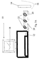
- Figure 1A illustrates a position detection system operative in accordance with a first preferred embodiment of the present invention.
- the system is designed for use in association with a computing device 10 having any kind of standard analog input 12.
- the system comprises a positional element 14, which takes up a position to be detected.
- the positional element may be a pointing device, for example a stylus or a mouse or the like which a user moves in order to interact with the computing device 10, or it may be a part of a robot or a playing piece for a game or any other kind of device whose position needs to be determined.
- the movement of the positional element 14 is tracked and the computer uses the movement or positioning of the element as an input to any current application that is able to make use of the input.
- a mouse or like device tends to be movement tracked whereas a stylus tends to be position tracked.
- Robots and game pieces may be either position or movement tracked depending on the application.
- the positional element simultaneously attains a position and emits signals which can be decoded to fix the position. If the positional element moves over a locus such as that indicated by dotted curve 16 then a suitable application may trace a corresponding curve 18 on the computer screen. Likewise the positional element may be used to write directly on the screen.
- the system further comprises a detector arrangement or base station 20, which detects the signals emitted by the positional element 14 in a manner that permits fixing of the position. That is to say the signal is designed to contain enough information to enable signal processing to fix the position of the positional element.
- the signals are preferably detected at two or three separate detectors 22 which are spaced apart.
- the number of detectors 22 is preferably selected for the number of co-ordinates that are required, that is to say the number of dimensions in which it is desired to follow the movement of the pointer.
- the base station preferably does not itself use the signals to calculate the coordinates of the pointing device but rather multiplexes the signals together onto a single channel.
- the channel is then provided to the analog input 12 of the computing device.
- the computing device simply needs to demultiplex the signals as received on its analog input and carry out triangulation or the like to assign co-ordinates to the pointing device.
- each detector picks up the same signal from the pointing device. However, because the detectors are at different positions, a phase difference or a time lag or the like is introduced, so that a position can be calculated from a differential between the detected signals.
- a preferred option is for the pointing device 14 to emit a combination of signals having different speeds.
- a receiver can then use the difference in arrival times of the two signals to calculate a distance to the receiver. Comparison of such distances between two receivers allows a two-dimensional position to be calculated and comparison between three receivers allows a position in three dimensions to be calculated.
- the pointing device 14 uses a combination of a light speed signal such as an infra-red signal and a sound speed signal such as an ultrasound signal.
- the distance to each receiver can then be calculated from the difference in arrival times of the two signals. It will be appreciated that the arrival of the infra-red signal is effectively instantaneous so that the base station 20 can be simplified by having a single infra-red sensor 24, and the two or three separate sensors 22 can be for sensing ultra-sound only.
- the analog input 12 is any input having access to an A/D converter.
- a typical example is the microphone input to a sound card.
- Another example is the line-in input to the sound card, and also a modem input can be used.
- a sound card has adequate processing ability both for demultiplexing and dealing with ultrasound signals, as will be discussed in greater detail below. If using the sound card then the microphone input is advantageous as it is able to power the base station.
- the present embodiment by utilizing the analog input and on-board processing ability, enables any machine that can digitize analog audio signals, for example PC's and larger computers, laptops and smaller computers including PDAs, cellular telephones, and other computing devices, to have a positioning ability added to them.
- the processing ability can conveniently be the digital sound capability that is practically universally available on these machines.
- a standard microphone input serves as an interface between various different sensors used for position detection, be they microphones, photo detectors, antennas and the like, and the computing device.
- any apparatus that has a free input which is sampled by A/D circuitry can use the embodiment in order to provide positioning ability without any hardware changes inside the apparatus.
- A/D sampling is carried out following filtering and amplification.
- client software is preferably located within the computing device, in order to retrieve the positioning data from the raw input signals.
- microphone input any analog input is suitable.
- Many PC's and laptops have more than one analog input, for example: microphone inputs, line-in inputs, and a modem input.
- Each of these analog inputs may be used as the connection to the positioning system described herein.
- microphone inputs have certain advantages over other kinds of analog inputs. Notably, power for the base station can be obtained from the microphone jack, and thus no separate connection is needed for the power source.
- a disadvantage specific to a modem input is that many modems do not have the ability to transfer raw data from the modem jack to the PC's memory. Instead, the data transferred from the modem is automatically processed as modem information.
- a disadvantage common to modem and line inputs is that the signal levels on the modem input and the line input must be higher by an order of magnitude than the signals on the microphone input. This adds a requirement for additional complexity and circuitry to the positioning system.
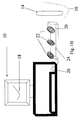
- Fig. 1B is a simplified block diagram illustrating a second preferred embodiment of the present invention. Parts that are the same as in previous figures are given the same reference numerals and are not described again except to the extent necessary for an understanding of the present figure.
- the embodiment of Fig. 1B differs from that of Fig. 1A in that decoding of the signals received from the pointing device is carried out in the base station 20.
- the base station thus is able to output digital co-ordinate position information regarding motion of the pointing device 14.
- the base station does not need to be connected to the analog input 12 and may instead be connected to any suitable digital input, or may be for stand alone use.
- Figs. 1A and 1B consist of 3 parts:
- the user is preferably supplied with sensing array apparatus or base station 20 and pointing device 14.
- the pointing device 14 preferably emits acoustic, and IR or electromagnetic signals.
- the emitted signals enable the array or the computing device or combination thereof to calculate the position of the pointer, and provide the calculated position to a local operating system or requesting application.
- the system is intended to be interfaced to the analog input of a computer or like device.
- a particularly useful analog input is the microphone input, and in order to interface to a standard microphone input, the following issues are considered:
- the preferred embodiments include wireless communication between the pointing device 14 and the base station 20, which is connected to the computer's microphone input.
- a simpler embodiment uses wired communication in which there is provided a cable connection between the base station and pointing device.
- the embodiment is particularly useful in a "mouse"-type implementation where relative position or movement is wanted and such an implementation is particularly simple and cost effective.
- a wired solution is not appropriate for many applications and thus a wireless solution is also needed.
- a preferred embodiment utilizes acoustic positioning.
- the idea of acoustic positioning is to measure a time difference between two signals of different speeds arriving at the sensor array. The time difference gives an indication of the distance to the source. If two different sensors are used then triangulation can be used to fix the source position. If three appropriately located sensors are used then a position in three dimensions can be obtained.
- the two signals are, in a preferred embodiment an acoustic signal and an IR or other electromagnetic signal.
- the velocity of sound waves at sea level is a known value.
- the IR or other electromagnetic signal travels at the speed of light and for the purposes of the precision levels of such a pointing device, is treated as being instantaneous.
- a coordinated release of the IR and sound signals is made.
- delays are measured between the arrival of the IR signal and the two versions of the sound signal at the two sensors.
- the two delays are converted into distance and the distances can be triangulated with the known distance between the microphones to give a 2-dimensional coordinate.
- a third microphone can receive a third version of the sound signal from which a third delay can be used to add a third co-ordinate. Suitable placement of the microphones may give an accurate three-dimensional co-ordinate.
- the above embodiment is relatively straightforward, and is applicable to hardware provided in some existing pointing devices.
- the Pointing Device The Pointing Device
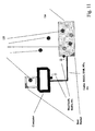
- Fig. 2 is a simplified diagram illustrating a positional element suitable for use in the above-described acoustic positioning embodiment.
- the positional element 14 is in the form of a pointing device and comprises a miniature speaker 26 which serves as a transducer to produce sound from electrical signals.
- the speaker is preferably optimized for ultrasonic wavelengths.
- an LED 28 may be provided to transmit the second, substantially instantaneous, signal.
- an antenna may be used to transmit other RF signals of suitable frequencies.
- Controlling logic 30 is preferably implemented by a microprocessor and provides coordination between the speaker 26 and the LED 28, to give a signal combination from which a meaningful delay can be determined.
- the controlling logic may provide other controlling functions as deemed necessary.
- Battery 32 provides power for the pointing device 14.
- the battery can be replaced by an inductive coil which is powered by induction from the base station. Such an alternative saves the need for battery replacement in the pointing device but limits range and adds complexity to the base station.
- a switch 34 may optionally be provided.
- the switch may be provided for any of a range of functions or may simply provide a signal whose purpose is decided by the operating system or application to which the signals are eventually submitted.
- the switch may be used to change the color of lines traced out on the computer screen, or in place of mouse clicks, or for shooting in games, or for indicating contact with a screen surface. In the latter case the switch may be designed to close upon physical contact with the screen.
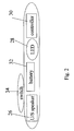
- Fig. 3A is a simplified diagram illustrating the internal components of a base station suitable for use with the pointing device of Fig. 2.
- the base station preferably comprises an array of at least 2 microphones 36 and 38 to pick up the signal from speaker 26. It will be appreciated that the microphones act as transducers to convert the sound back to electrical signals.
- an IR photodiode 40 detects the IR signal from LED 28.
- an antenna may replace the IR photodiode, as explained above.
- Pre-amp and filtering circuitry 42 is preferably provided for each of the sensors 36, 38 and 40.
- Time or frequency multiplexing functionality 44 allows the signal to be multiplexed onto a single channel.
- Frequency down-conversion and mixer functionality 45 allows the signals as received to be converted downwards to frequencies compatible with the analog input that is being used.
- a microprocessor 46 or other controlling logic is used to control and coordinate the base station. Synchronization data allows the microprocessor to synchronize the signaling components.
- a cable and jack 48 are provided for connection to the computing device's microphone socket, or any other input having an A/D converter. Data into the analog input is preferably buffered and filtered by buffer and filter circuitry 49. Buffering may be different depending on whether a microphone socket or some other input is used.
- Power supply circuitry 50 permits usage of the microphone jack simultaneously as a power source for the base station and for data output.
- the clock of the positional element that is the pointing device or wireless terminal
- the synchronization of the wireless terminal and the base station can be achieved with IR or RF signals, as described herein. Synchronization further on down the line with the host time base is in many cases impossible. Even with a relatively high sampling rate such as 50KHz, the mismatch between the IR synchronization signal and the A/D sample may be in the order of 20uSec, which correspond to few centimeters in the measured location. Such imprecision is not suitable for most applications. Furthermore, even if good synchronization is achieved at a certain instance, the clocks of the two systems, namely the host and the base station, tend to drift over time due to limited accuracy of existing crystal technologies.
- the base station preferably uses a certain time or frequency slot to transmit to the host a synchronization pattern which is at the Nyquist rate of the host A/D converter.
- the host can use the pattern to determine the phase difference between its own clock and the positioning time base clock.
- the synchronization pattern can be transmitted at a regularity sufficient to compensate for clock drift, and there is no need to send such a signal at every loop cycle.
- the base station circuitry sends commands to the positional element, whether by acoustic, light, infra-red, RF or any other form of signal that the pointing device is capable of responding to.
- the positional element 14 has RF or light receivers.
- the pointing device may emit a signal such as the acoustic signal discussed above.
- the time of emission of the instruction from the base station is known, and can be used to start timing a delay in receipt of the acoustic signal.
- the respective delays of the acoustic signals at the different microphones can again be used to arrive at position co-ordinates.
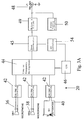
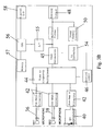
- FIG. 3B A base station for the embodiment of Fig. 1B is shown in Fig 3B. Parts that are the same as in Fig. 3A are given the same reference numerals and are not described again except to the extent necessary for an understanding of the present figure.
- an A/D converter 55 takes the output of the down conversion 45 and provides it to CPU 56.
- CPU 56 is connected to a memory 57 and a digital data port 58.
- the CPU carries out decoding of the waveform to determine the position of the positional element 14 and may additionally run applications using the positional information thus determined.
- the features are preferably provided within a base station chipset.
- the solution leads to a more complex and therefore costly base station than that of Fig. 3A.
- the circuitry can be dedicated for use with the signal-to-co-ordinate decoding algorithm to be described below, and thus is still relatively simple in comparison with currently available solutions.
- a decoding algorithm is preferably provided to convert digitized versions of the pointing device signals into position coordinates for passing to a local operating system or directly to an application or the like.
- the algorithm is preferably provided as part of client software for the computing device, either as a driver for the base station or built in to the local operating system or exceptionally as part of a specific application.
- the algorithm may be incorporated into the base station electronics.
- the algorithm preferably takes into account the relatively low sampling frequency capabilities likely to be available by carrying out frequency down conversion.
- the conversion reduces the data frequency from the relatively high frequencies needed for transmission from the positional element to the relatively low frequencies that installed sound hardware is likely to be able to sample and digitize.
- the algorithm preferably includes an ability to handle noise and is preferably adapted for specific issues in the handling of low frequency signals in general.
- the known art in the position location field concentrates on the use of very short and energetic acoustic signals as the location signal.
- the known solutions dictate high sampling frequencies, typically higher than 400KHz, in order to be able to find such short location signals and not miss them entirely.
- the present embodiments by contrast preferably do not use sampling rates higher than 44.1KHz, since such frequencies are incompatible with the installed base of sound processing equipment.
- the data can be frequency modulated (FM) or phase modulated (PM) onto the carrier comprising the ultrasonic signal, or any other known method may be used.
- the algorithm preferably operates to decode the modulated signal and to reconstruct the original position-information bearing signal from the results of sampling thereof. In the present embodiment it is preferred to use band-limited signals in order to achieve a desired resolution level.
- continuous wave (CW) modulations such as spread spectrum and frequency hopping are used, in acoustic position finding, to overcome reverberation and multipath effects.
- more than one detector is used, and the signals from the detectors are multiplexed for a single input.
- the need for multiplexing may be avoided.
- a stereo input sound blaster ® or similar stereo sound card one can feed two signals into the microphone input, and another two signals to the "Line-In" input, making a total of four signals that do not need to be multiplexed together.
- the base station does not require a time division multiplexer for input access purposes. Rather, up to four sensors may be fed directly to the sound card, and the sound blaster's ® internal circuitry is then able to take care, using an appropriate software driver, of the received signals. It is noted, however, that even stereo input sound blasters have a maximum of two A/D converters, so that time division multiplexing is still needed to enable the sound card to carry out sampling over more than two channels simultaneously.
- the transmitted signals may thus be synchronized with each other by the base station.
- Such synchronization may be achieved in a number of ways.
- One way is to send synchronization data from or to the base station alongside the signals themselves.
- Another method requires cyclic transmission, that is to say the signals are sent in a coordinated manner so that a signal period or phasing between the channels that is known to both sides is used.
- the methods hereinbefore described thus provide data synchronization, both with and without an internal time division mechanism.
- Another drawback is that relatively complex software driving functionality is required to keep switching timing between the microphone input and the "Line In" input as accurate as possible. A jitter of a mere 1 ⁇ Sec between the switching timings can result in 0.3mm of measurement inaccuracy at room temperature.
- Additional cost may be added because, in order to use the additional inputs, an additional connector and wiring have to be provided on the base station, which most users will not be able to utilize.
- a preferred embodiment of the present invention uses a maximum likelihood detector for decoding the signals received from the sensors to determine the distances to the individual sensors.
- the signals received from the sensors, via the base station are compared to reference signals. The comparison indicates a most likely signal and from the most likely signal a distance is determined as the distance from which the signal was most likely transmitted.
- the maximum likelihood detector preferably uses a full mathematical model of the channel to construct a look up table of reference signals against which to compare received signals so that a best match distance can be found.
- the expected waveform can be sampled at the Nyquist rate, and any timing mismatch between the sampling points can be overcome by extrapolation functions, to reveal the distance.
- Fig. 4 is a simplified block diagram indicating typical components of a mathematical model for incorporating into a maximum likelihood detector of the kind considered above.
- the model 60 comprises an initial signal sequence S(t) which is fed into the transfer function H1(s) of the transducer 26 within the mobile unit 14.
- the mobile unit is followed by air gap 62 which is modeled simply as a delay. The air gap is altered for different distances.
- the result is then fed to the reception path in the base station 20 which includes transfer function H2(s) for the microphone 36, equalization H3(s), and low pass filtering H4(s) as well as mixing and any other features of the path.
- transfer function H2(s) for the microphone 36 equalization H3(s), and low pass filtering H4(s) as well as mixing and any other features of the path.
- the full modeling of the channel is useful in the design of the maximum likelihood detector in that it allows accurate expected signals to be constructed against which the received signals ideally differ only in phase. The detector is then relatively easily able to distinguish the most likely signal, which in turn corresponds to the most likely distance.
- the IR signal is used in the maximum likelihood based scheme both to set the start of the delay and also to synchronize clocks between the mobile unit and the base station.
- Synchronization path 64 is indicated on the model. Specifically, path 64 provides a synchronization signal to the local oscillator.
- acoustic signals have differing angular transfer functions.
- An equalizer can be added to the base station in order to compensate for this fact.
- the IR (or other electromagnetic) signal preferably also points, via a second path 66, to a start time equivalent to a zero distance in a distance look up table 68.
- the most likely signal obtained by the maximum likelihood detector is then used to identify a most likely non-zero distance from the look up table.
- a look-up table it is possible to use an array generated on the fly.
- other detectors may be used; and there are several known decoders of FM signals, such as PLLs, I/Q demodulation, phase multiplication etc.
- Fig. 5 is a two-part graph showing a typical correlation function that may be used. The top part of the graph shows the function, and the lower part of the graph is an enlarged or zoomed view of the upper central part of the graph.
- Fig. 6 is a simplified block diagram showing a decoding unit 70 for carrying out decoding as described above.
- the decoding unit 70 comprises a maximum likelihood detector 72 which uses channel model 60 as described with reference to Fig. 4 above, and look-up table 68.
- the maximum likelihood detector 72 is followed by correlator 74, which uses correlation function 76 to carry out correlation using the distance detected as most likely by the maximum likelihood detector 72, to confirm that the detected distance is correct.
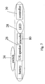
- Fig. 7 is a simplified diagram showing a pointing device according to a further preferred embodiment of the present invention. Parts that are the same as in previous figures are given the same reference numerals and are not described again except to the extent necessary for an understanding of the present figure.
- the pointing device of Fig. 7 differs from that of Fig. 2 in that it additionally comprises an encoding unit 80, connected between the LED 28 and the speaker 26.
- Encoding unit 80 provides additional coding of the signal prior to output to speaker 26. Additional coding of the signal can be used for greater signal robustness and also to minimize interference with neighboring users. The latter has several benefits.
- Each mobile unit preferably has a pseudo-random frequency hopping sequence incorporated within encoding unit 80, or if preferred within controller 30.
- the base station, or the decoding unit as preferred has a corresponding dehopping unit which is able to synchronize on the same hopping sequence.
- a preferred embodiment provides synchronization by using the IR or other electromagnetic, signal to transfer the hopping sequence to the base station.
- Another preferred embodiment uses factory calibration to provide a sequence.
- One of the applications that can be realized with a position detection system based on frequency hopping is integration of the base station 20 of the system with a WLAN base station.
- the result is an enhanced WLAN and positioning base station able to support multi users and able to manage each of the users data separately.
- the users are able for example to write on paper or on their own electronic pads using pointing devices belonging to or compatible with the WLAN.
- Unseen, the WLAN traces the movements of each of the users separately and produces networked electronic versions of each of their hand written documents.
- the pointing device 14 is a combination of the pointing device of Fig. 2 and a standard pen.
- Typical data for setting in this way includes:
- the positional element 14 may additionally be supplied with a pressure sensor, whose output can be used by appropriate applications to allow graphical or security features. For example a line may be drawn differently depending on the pressure applied.
- a suitable pressure sensor for incorporation into a pointing device may comprise a digitizer (10 bits or less), a strain gauge and a driving circuit.
- a suitable angle sensor for incorporation into pointing device 14 may comprise a tilt gauge, digitizer and driving circuit.
- two position indicators such as ultrasonic loudspeakers may be placed at either end of the pointing device, each transmitting in a manner that renders the signals distinguishable. The angle of the pointing device may then be derived by calculating each of the positions and performing simple geometry between them.
- base station 20 includes the ability to decode signals without the support of the host computing device 10.
- the decoding algorithm described hereinabove does not require especially powerful processing power and it is thus feasible to include a limited resource CPU into the base station without increasing the overall cost.
- a computation power of ⁇ 1 MIPS is used to decode the signals.
- Such low computation power can in fact be integrated into a single customized base station chip, or as a low cost add-on.
- the use of such a CPU allows a more conventional connection to hosts, such as: UART, USB, Serial and others since the signal that is transferred is the processed result of the positioning and not the raw signals.
- Such an output is also suitable for direct use within WLAN and BlueTooth.
- Such a stand-alone base station preferably includes a digitizing element, (A/D converter), a CPU, a memory and interface circuitry.
- a sensor 90 comprises two LEDs 92 and 94 offset by a predetermined angle.
- a differential amplifier 96 is connected, via each of its two differential inputs, between the two LEDS 92 and 94 so as to measure the difference between levels of current in each of the LEDs.
- LED 28 in the pointing device 14 produces a narrow light beam whose direction can be measured from the sensor.
- the sensor 90 is preferably constructed with optics in the form of lenses 98 and 100 to cover the sensing area and ensure that light coming from a predetermined field view falls directly onto the sensing area.
- the base station is essentially the same as that in Fig. 3, except that in place of microphones there are light direction finding sensors 90 and the separate IR photodiode is not needed since all of its synchronizing and like functions can be taken over by the photodiodes of the light direction finding sensors.
- the corresponding decoding algorithm deals with a different kind of information part of the signal but the underlying information is dealt with substantially in the same way. Finding both a direction and distance is akin to the principles behind stereoscopic vision and angles at two sensors are found and triangulated to give a position. Otherwise the same issues apply as to the decoding algorithm of the previous embodiments, namely issues of the low sampling rates and low frequencies needed if the system is to take advantage of the analog input and the computing device hardware.
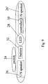
- FIG. 9 is a simplified diagram showing the positional element of Fig. 2 adapted for attitude detection. Parts that are the same as in Fig. 2 are given the same reference numerals and are not described again except to the extent necessary for an understanding of the present figure.
- a second speaker 26' is provided at a predetermined distance from the first speaker 26. Preferably the two speakers are provided at opposite ends of the element. Each speaker issues a separate waveform which is separately detected and the attitude of the element is determined by drawing a straight line between the two positions.
- the two speakers preferably are able to identify themselves to the detectors and to operate simultaneously. Their respective signals may be time or frequency multiplexed to work together and in one preferred embodiment the two speakers use frequency hopping, each using a different pseudo-random sequence.
- a board with orthogonally arranged magnetic loops serves as a writing pad.
- a pointing device emits electromagnetic signals, which are picked up by the pad's magnetic loops. By analyzing the signals, the pointing device's position can be calculated.
- the loops can be printed onto a PCB and can be made small enough to give any desired level of precision.
- the pointing device is the same as that of Fig. 2, except that the LED 28 is replaced by an electromagnetic transmitter including an emitting antenna and associated modulating circuitry.
- the base station comprises built in loops as sensors with RF demodulating circuitry but otherwise is the same as the base station of Fig. 3.
- the decoding algorithm again has to deal with a different kind of information part of the signal but otherwise covers the same issues as those discussed above.
- the positioning system of the present embodiments has a wide range of applications, a few of which are listed below.
- a single electronic device is manufactured, and is set up in different ways for the chosen application, possibly by the use of jumper or dip switches.
- the switches may allow configuration of the system for the most appropriate trade-offs for the given application.
- low power consumption is important.
- accuracy of positioning is critical.
- accuracy is less important than rapid updating and the number of samples per second.
- range is important, and in yet others the ability to accommodate large numbers of users may be critical.
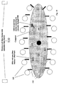
- Fig. 10 is a simplified diagram illustrating a conference room fitted with a global tracking system.
- the global tracking system comprises a wireless LAN system 110 with an embedded base station according to the present embodiments.
- a series of users 112 in the conference room have positional elements 114 according to the preferred embodiments. Each positional element has its own unique identity as described above.
- the various positional elements transmit waveforms, and the waveforms are detected by the global tracking system.
- the waveforms may additionally be tracked by tracking systems local to the user, such as standalone base stations 116, cellular telephone 118 with built in base station, and the like.
- the conference table itself may have its own master base station 120 combined with the conference room telephone facility.
- Toys with positioning can be divided into three sub-categories, to be explained below:
- Fig. 13 is a simplified diagram illustrating an inventory system according to an embodiment of the present invention. Positional elements are embedded in items of stock 140 it is desired to inventory and a base station 142 is provided in the premises to track movement. Such a system is advantageous in tracking stock that moves frequently and for which updated information is needed.
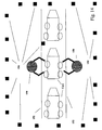
- Fig. 14 shows a number of robots 150 arranged about a production line 152.
- Each robot has a production task and limbs and mobility to carry out the task.
- Base stations 154 keeps global control of the robots.
- Each robot may have a positional element for the robot as a whole and/or positional elements for each limb whose position is needed for the kind of maneuvers intended.
- each robot includes its own standalone base station and makes its decisions based on incoming positional data from itself and from the surrounding robots.
- each robot only has positional elements and control circuitry. Tracking is carried out by the external base stations 154 which then instruct the robots on how to move. Thus only minimal number of intelligent devices need be provided, and relatively unsophisticated robots can provide group behavior.
- Higher precision can be achieved by putting additional wireless terminals in the detection space, at pre-determined locations. Measuring these units will calibrate the absolute measurement of the moving terminals so that a greater precision can be achieved.
- a pointing device with a base station can be incorporated into an electronic identification scheme.
- Personal written signatures are often used for identification but a skilled forger is able to copy other persons' signatures. A forger however, copies the outward appearance of the signature and not the way in which the user applies pressure to the pen or holds the pen, say at a given angle on a given part of the signature.
- Systems for obtaining signature information which incorporate pressure as well as the outward appearance are in use, however, use of the present embodiments makes such a system cheaper and more flexible.
- attitude information of the pen allows for greater verification.
- the angle of the pen can be measured by adding an additional angle sensor to the pen.
- the angle sensor may comprise an accelerometer or may use an additional location signal transmitter on the other side of the stylus, as described above.
- the base station determines the XYZ locations of the two transducers, from which the angle of the stylus can be calculated. The angle is then used as additional factor and results in an electronic version of the signature which is a triplet of three vector values (XY location, pressure, angle).
- the following embodiments describe an enhanced identification apparatus, which integrates positioning with other security methods.
- a pointing device in the form of a stylus as an authentication means.
- a group of styluses are provided as part of the system. One of these styluses is provided to each of an identified group of users and each stylus is provided with its own electronic identity.
- the stylus By identifying the stylus, the user presently interacting with the system is identified and this allows verifiable usage of the system in security-wise applications.
- the user may also be required to provide his usual signature, which may be electronically verified based on movement and applied pressure or the like.
- a stylus can also be provided with a feature to enable a digital signature, for example based on the Public Key Infrastructure (PKI).
- PKI Public Key Infrastructure
- the user may sign with his usual hand-written signature. Once the hand signature is verified, the system uses the stylus to provide a digital signature to the document using a PKI algorithm.
- PKI Public Key Infrastructure
- Such a feature requires 2-way communication between the pointing device and the base station, which can be provided using available IR or RF channels. The electronic signature thus provides a guarantee both that the personalized stylus was used and that the authorized user was verified.
- a keypad may be added to allow the user to enter a personal identification number (PIN).
- PIN personal identification number
- the system may further incorporate a biometric sensor to the stylus or the base station to increase the security level.
- the biometric sensor may be for fingerprint recognition, retinal signature recognition, voice signature recognition and the like.
- a stylus or digital pen may additionally be used for:
Claims (102)
- Système de détection de position pour une utilisation en association avec des applications informatiques, le système comprenant :un élément positionnel (14) pour atteindre une position et comprenant un premier émetteur pour émettre une forme d'onde ultrasonique continue, etun agencement de détecteurs (20) pour détecter ladite forme d'onde de façon à permettre de fixer ladite position et de délivrer ladite forme d'onde pour le calcul, d'une manière à conserver ladite capacité de fixation de position,caractérisé en ce que :ladite forme d'onde ultrasonique comprend :une onde porteuse, et une modulation intégrée sur ladite onde porteuse de laquelle dériver ladite fixation de ladite position.
- Système de détection de position selon la revendication 1, dans lequel ledit agencement de détecteurs (20) est utilisable pour émettre ladite forme d'onde décodable pour fixer ladite position, de sorte que ladite forme d'onde soit décodable à une basse fréquence d'échantillonnage.
- Système de détection de position selon la revendication 1, dans lequel ladite forme d'onde comprend une périodicité.
- Système de détection de position selon la revendication 2, dans lequel ladite sortie comprend la fourniture de ladite forme d'onde décodable à une basse fréquence d'échantillonnage à au moins une entrée analogique d'un dispositif informatique pour ledit calcul.
- Système de détection de position selon la revendication 4, dans lequel ladite sortie comprend la fourniture de ladite forme d'onde à au moins deux entrées analogiques dudit dispositif informatique.
- Système de détection de position selon la revendication 1, comprenant une pluralité d'éléments de positionnement, et dans lequel ledit agencement de détecteurs (20) est configuré pour fournir des formes d'onde respectives en tant que canaux distincts pour ladite sortie.
- Système de détection de position selon la revendication 6, comprenant en outre une pluralité d'agencements de détecteurs (20) pour apporter une plus grande précision de détection.
- Système de détection de position selon la revendication 6, dans lequel lesdits canaux distincts sont multiplexés dans le temps ou sont multiplexés en fréquence.
- Système de détection de position selon la revendication 6, dans lequel chaque élément de positionnement comprend en outre un modulateur pour moduler ladite forme continue.
- Système de détection de position selon la revendication 9, dans lequel ledit modulateur est un modulateur de fréquence.
- Système de détection de position selon la revendication 10, dans lequel chaque élément de positionnement est fourni avec une séquence de saut de fréquence pour permettre l'utilisation simultanée de ladite pluralité d'éléments de positionnement.
- Système de détection de position selon la revendication 11, dans lequel chaque dite séquence de saut de fréquence est une séquence pseudo aléatoire différente.
- Système de détection de position selon la revendication 9, dans lequel ledit modulateur est un modulateur d'amplitude.
- Système de détection de position selon la revendication 9, dans lequel ledit modulateur est utilisable pour moduler des données supplémentaires aux données positionnelles sur ladite forme d'onde.
- Système de détection de position selon la revendication 6, dans lequel chaque élément de positionnement comprend un identifiant unique.
- Système de détection de position selon la revendication 1, dans lequel ladite onde continue est modulée.
- Système de détection de position selon la revendication 16, dans lequel ladite onde continue est modulée en utilisant un spectre étalé.
- Système de détection de position selon la revendication 16, dans lequel ladite onde continue est modulée en utilisant la modulation à division de temps.
- Système de détection de position selon la revendication 1, dans lequel ledit élément positionnel (14) comprend un capteur biométrique.
- Système de détection de position selon la revendication 1, dans lequel l'agencement de détection comprend une pluralité de récepteurs pour assurer la détection multidimensionnelle de ladite position.
- Système de détection de position selon la revendication 20, dans lequel ladite sortie comprend la fourniture de ladite forme d'onde décodable à une basse fréquence d'échantillonnage à une entrée analogique d'un dispositif informatique pour ledit calcul et est en outre utilisable pour multiplexer des signaux de ladite forme d'onde à partir de chacun de ladite pluralité de récepteurs pour ladite entrée sur ladite entrée analogique.
- Système de détection de position selon la revendication 21, utilisable pour employer une capacité de démultiplexage dudit dispositif informatique pour démultiplexer lesdits signaux reçus à ladite entrée analogique.
- Système de détection de position selon la revendication 1, dans lequel ledit élément positionnel (14) comprend en outre un deuxième émetteur pour émettre un signal supplémentaire à ladite forme d'onde continue et ayant une vitesse différente de celle-ci, pour ainsi obtenir des données indicatives d'une distance entre ledit élément positionnel (14) et les détecteurs dudit agencement de détecteurs (20) à partir d'un délai entre ladite forme d'onde continue et ledit signal supplémentaire.
- Système de détection de position selon la revendication 23, dans lequel ledit signal supplémentaire est un signal de vitesse de lumière.
- Système de détection de position selon la revendication 24, dans lequel le signal de vitesse de lumière est un signal infrarouge.
- Système de détection de position selon la revendication 1, dans lequel ladite sortie comprend la fourniture de ladite forme d'onde à une entrée analogique d'un dispositif informatique.
- Système de détection de position selon la revendication 26, dans lequel ladite entrée analogique est une entrée sur un convertisseur d'analogique en numérique.
- Système de détection de position selon la revendication 27, dans lequel ledit convertisseur d'analogique en numérique fait partie d'une carte son.
- Système de détection de position selon la revendication 27, dans lequel ladite entrée analogique est au moins l'une d'une entrée de microphone, d'une entrée de ligne et d'une entrée de modem.
- Système de détection de position selon la revendication 29, dans lequel ledit agencement de détecteurs (20) est configuré pour être alimenté électriquement par ledit dispositif informatique par l'intermédiaire de ladite entrée analogique.
- Système de détection de position selon la revendication 1, dans lequel ladite manière de conservation de ladite capacité de fixation de position comprend la conservation de ladite capacité sur un échantillonnage de basse fréquence.
- Système de détection de position selon la revendication 31, dans lequel ledit échantillonnage de basse fréquence comprend un taux compatible avec l'échantillonnage à taux de Nyquist de signaux sonores.
- Système de détection de position selon la revendication 32, dans lequel ledit taux est inférieur à 50 kHz.
- Système de détection de position selon la revendication 32, dans lequel ledit taux est sensiblement égal à 44 kHz.
- Système de détection de position selon la revendication 32, dans lequel ledit taux est sensiblement égal à 6 kHz.
- Système de détection de position selon la revendication 1, dans lequel le système comprend en outre une unité de décodage pour effectuer ledit calcul pour décoder ladite forme d'onde et indiquer ladite position.
- Système de détection de position selon la revendication 36, dans lequel ladite unité de décodage comprend un détecteur de probabilité maximum pour effectuer ledit décodage en trouvant la distance la plus probable.
- Système de détection de position selon la revendication 37, dans lequel ledit détecteur de probabilité maximum comprend un modèle de canal pour modéliser le passage de ladite forme d'onde dudit élément positionnel (14) à ladite unité de décodage de forme d'onde, pour ainsi fournir un signal de référence par rapport auquel identifier ladite distance la plus probable.
- Système de détection de position selon la revendication 37, dans lequel ledit détecteur de probabilité maximum est suivi d'un corrélateur pour confirmer ladite distance la plus probable.
- Système de détection de position selon la revendication 1, comprend en outre un synchroniseur pour la synchronisation entre ledit agencement de détecteurs (20) et ledit élément positionnel (14).
- Système de détection de position selon la revendication 40, dans lequel ledit synchroniseur est utilisable pour employer au moins l'une de la signalisation infrarouge (IR) et de la signalisation de radiofréquence (RF) pour effectuer ladite synchronisation.
- Système de détection de position selon la revendication 40, dans lequel ledit synchroniseur est utilisable pour surveiller les écarts de synchronisation pour ainsi réduire la fréquence à laquelle les synchronisations répétitives sont effectuées.
- Système de détection de position selon la revendication 40, dans lequel ladite synchronisation s'effectue avec un oscillateur local au dit élément positionnel (14).
- Système de détection de position selon la revendication 40, dans lequel ledit synchroniseur est en outre utilisable pour ajouter un signal de synchronisation ladite forme d'onde, pour ainsi la synchroniser avec un dispositif hôte.
- Système de détection de position selon la revendication 1, dans lequel ledit élément positionnel (14) est câblé à ladite matrice de détecteurs.
- Système de détection de position selon la revendication 1, dans lequel ledit élément positionnel (14) comprend un codeur numérique pour coder les données numériques dans ladite forme d'onde continue.
- Système de détection de position selon la revendication 36, dans lequel ladite unité de décodage de forme d'onde est fournie en tant que programme client pour l'installation dans un dispositif informatique.
- Système de détection de position selon la revendication 36, dans lequel ladite unité de décodage de forme d'onde est fournie en tant que programme client pour l'installation dans un système d'exploitation d'un dispositif informatique.
- Système de détection de position selon la revendication 36, dans lequel ladite unité de décodage de forme d'onde est intégrée au dit agencement de détecteurs (20).
- Système de détection de position selon la revendication 1, dans lequel ledit élément positionnel (14) comprend en outre un capteur de pression pour fournir des données de pression exercée sur ledit élément positionnel (14).
- Système de détection de position selon la revendication 1, dans lequel ledit élément positionnel (14) comprend en outre une détection d'altitude pour fournir des données sur l'altitude à laquelle ledit élément positionnel (14) est maintenu.
- Système de détection de position selon la revendication 1, dans lequel ledit élément positionnel (14) comprend en outre :un capteur de pression pour fournir des données de pression exercée sur ledit élément positionnel (14), etune détection d'altitude pour fournir des données sur l'altitude laquelle ledit élément positionnel (14) est maintenu.
- Système de détection de position selon la revendication 52, dans lequel ladite détection d'altitude comprend deux transmetteurs de forme d'onde placés à une distance prédéterminée l'un de l'autre sur ledit élément positionnel (14), chacun d'eux pour une détection positionnelle distincte.
- Système de détection de position selon la revendication 52, étant utilisable pour extraire d'un utilisateur dudit élément positionnel (14), une triplette de vecteurs de mouvement, de pression et d'altitude.
- Système de détection de position selon la revendication 1, comprenant outre une fonctionnalité de signature électronique fournie dans ledit élément positionnel (14).
- Système de détection de position selon la revendication 55, comprenant en outre une fonctionnalité de signature biométrique fournie dans ledit élément positionnel (14).
- Système de détection de position selon la revendication 1, dans lequel ledit élément positionnel (14) comprend en outre un récepteur pour recevoir des données de contrôle.
- Système de détection de position selon la revendication 1, étant en outre utilisable pour relayer des données de ladite position à d'autres éléments.
- Système de détection de position selon la revendication 1, dans lequel ladite matrice de détecteurs est associée à un dispositif de téléphonie cellulaire, pour ainsi fournir une capacité d'entrée d'écriture pour ledit dispositif de téléphonie.
- Système de détection de position selon la revendication 59, comprenant en outre une application pour utiliser ladite entrée d'écriture en tant qu'entrée de numérotation pour ledit dispositif de téléphonie.
- Système de détection de position selon la revendication 1, comprenant en outre :une application de calcul d'emplacement, etune application de conversion d'écriture manuscrite en texte,pour fournir une interface d'écriture manuscrite en numérique.
- Système de détection de position selon la revendication 61, comprenant en outre au moins l'une d'une application de conversion de texte en discours et d'une application de traduction de langue, pour ainsi fournir la lecture ou la traduction à partir de ladite entrée d'écriture manuscrite.
- Système de détection de position selon la revendication 54, comprenant en outre :une fonctionnalité de signature électronique fournie dans ledit élément positionnel (14), etune fonctionnalité de vérification pour vérifier les triplettes extraites de signatures d'utilisateurs, le système étant utilisable pour permettre ladite fonctionnalité de signature électronique avec la vérification par ladite fonctionnalité de vérification d'une signature d'utilisateur.
- Système de détection de position selon la revendication 1, dans lequel ledit élément positionnel (14) est un localisateur personnel pour l'attachement à une personne.
- Système de détection de position selon la revendication 1, dans lequel ledit élément positionnel (14) est un localisateur d'article pour l'indication de l'emplacement d'un article dans un espace.
- Système de détection de position selon la revendication 64, dans lequel il est en outre fourni une application pour calculer ledit emplacement et émettre des signaux de contrôle en réponse au dit emplacement.
- Système de détection de position selon la revendication 65, dans lequel il est en outre fourni une application pour calculer ledit emplacement et émettre des signaux de contrôle en réponse au dit emplacement.
- Système de détection de position selon la revendication 66, dans lequel lesdits signaux de contrôle sont au moins l'un des signaux pour diriger le foyer d'un système de son stéréo, des signaux pour diriger une caméra, des signaux pour diriger une communication entrante et des signaux pour diriger un robot.
- Système de détection de position selon la revendication 65, dans lequel lesdits signaux de contrôle sont des signaux pour diriger une caméra, des signaux pour diriger un robot, des signaux pour diriger une machine, des signaux pour diriger une séquence prédéterminée, des signaux pour diriger une séquence d'assemblage et des signaux pour diriger une séquence de réparation
- Système de détection de position selon la revendication 1, comprenant une pluralité d'unités, chaque unité comprenant l'un desdits éléments positionnels (14) et l'une desdites matrices de détecteurs, dans lequel chaque unité est utilisable pour localiser toutes les unités adjacentes, pour ainsi fournir un enchaînement desdites unités.
- Système de détection de position selon la revendication 70, dans lequel chaque unité comprend un identifiant unique.
- Système de détection de position selon la revendication 64, dans lequel ledit élément positionnel (14) fait partie d'un accessoire de jeu de réalité virtuelle.
- Procédé de détection de position à utiliser en association avec un dispositif informatique ayant une entrée analogique, le procédé comprenant les étapes consistant à :utiliser un élément positionnel (14) pour atteindre une position,émettre une forme d'onde ultrasonique continue comprenant une onde porteuse et une modulation intégrée sur ladite onde porteuse, ladite modulation étant décodable pour fixer ladite position, etdétecter ladite forme d'onde de façon à permettre la fixation de ladite position et la sortie de ladite forme d'onde de manière à conserver ladite capacité de fixation de position, pour ainsi fournir au dit dispositif informatique une indication de ladite position.
- Procédé de détection de position selon la revendication 73, dans lequel ladite sortie comprend la sortie de ladite forme d'onde en tant que signal analogique.
- Procédé de détection de position selon la revendication 74, comprenant en outre le décodage de ladite forme d'onde au niveau dudit dispositif informatique pour extraire des données de ladite position.
- Système de détection de position selon la revendication 1, comprenant en outre un décodeur de signal (70) pour recevoir ladite forme d'onde dudit agencement et décoder ladite position atteinte à partir de ladite forme d'onde.
- Système de détection de position selon la revendication 76, dans lequel ledit agencement de détecteurs (20) et ledit décodeur de signaux (70) sont connectés par l'intermédiaire d'une liaison analogique.
- Système de détection de position selon la revendication 76, dans lequel ledit élément positionnel (14) est utilisable pour émettre ladite forme d'onde décodable pour fixer ladite position de sorte que ladite forme d'onde soit décodable à une basse fréquence d'échantillonnage.
- Système de détection de position selon la revendication 76, dans lequel ladite forme d'onde est une forme d'onde sensiblement continue.
- Système de détection de position selon la revendication 76, dans lequel ledit agencement de détection comprend une pluralité de détecteurs de signaux agencés à différents emplacements chacun séparément pour détecter ladite forme d'onde, pour ainsi fournir ladite fixation de position en tant qu'informations différentielles entre lesdits signaux détectés.
- Système de détection de position selon la revendication 80, dans lequel ledit décodeur de signal (70) comprend au moins un signal de référence construit en utilisant un modèle dudit système et un détecteur de probabilité maximum pour déterminer la position la plus probable sur la base dudit signal de référence.
- Système de détection de position selon la revendication 81, dans lequel ledit décodeur comprend en outre un corrélateur (74) pour utiliser une fonction de corrélation pour confirmer ladite position la plus probable.
- Système de détection de position selon la revendication 76, dans lequel ledit élément positionnel (14) est utilisable pour émettre une combinaison de signaux ayant différentes vitesses pour permettre à un récepteur de calculer une distance à celui-ci à partir d'un délai entre eux.
- Système de détection de position selon la revendication 83, dans lequel ladite combinaison comprend un signal à la vitesse de la lumière et un signal à la vitesse du son.
- Système de détection de position selon la revendication 84, dans lequel le signal à la vitesse de la lumière est un signal infrarouge.
- Système de détection de position selon la revendication 84, dans lequel le signal a la vitesse du son est un signal ultrasonique.
- Système de détection de position selon la revendication 76, dans lequel ladite manière de conservation de ladite capacité de fixation de position comprend la conservation de ladite capacité sur un échantillonnage de basse fréquence.
- Système de détection de position selon la revendication 87, dans lequel ledit échantillonnage de basse fréquence comprend un taux compatible avec l'échantillonnage à taux de Nyquist de signaux sonores.
- Système de détection de position selon la revendication 88, dans lequel ledit taux est inférieur à 50 kHz.
- Système de détection de position selon la revendication 88, dans lequel ledit taux est sensiblement égal à 44 kHz.
- Système de détection de position selon la revendication 88, dans lequel ledit taux est sensiblement égal à 6 kHz.
- Système de détection de position selon la revendication 76, dans lequel ledit élément positionnel (14) comprend en outre un capteur de pression pour fournir des données de pression exercée sur ledit élément positionnel (14).
- Système de détection de position selon la revendication 76, dans lequel ledit élément positionnel (14) comprend en outre une détection d'altitude pour fournir des données sur l'altitude à laquelle ledit élément positionnel (14) est maintenu.
- Système de détection de position selon la revendication 76, dans lequel ledit élément positionnel (14) comprend en outre :un capteur de pression pour fournir des données de pression exercée sur ledit élément positionnel (14), etune détection d'altitude pour fournir des données sur l'altitude à laquelle ledit élément positionnel (14) est maintenu.
- Système de détection de position selon la revendication 94, qui est utilisable pour extraire à partir d'un utilisateur dudit élément positionnel (14), une triplette de vecteurs de mouvement, de pression et d'altitude.
- Système de détection de position selon la revendication 76, comprenant en outre une fonctionnalité de signature électronique fournie dans ledit élément positionnel (14).
- Système de détection de position selon la revendication 95, comprenant en outre :une fonctionnalité de signature électronique fournie dans ledit élément positionnel (14), etune fonctionnalité de vérification pour vérifier les triplettes extraites de signatures d'utilisateurs, le système étant utilisable pour permettre ladite fonctionnalité de signature électronique avec la vérification par ladite fonctionnalité de vérification d'une signature d'utilisateur.
- Système de détection de position selon la revendication 1, dans lequel ledit élément positionnel (14) comprend en outre un deuxième émetteur pour émettre une autre forme d'onde continue modulée pour être décodable pour fixer ladite position, ledit deuxième émetteur étant positionné à une distance prédéterminée dudit premier émetteur, et
ledit agencement de détecteurs (20) est utilisé pour permettre la détermination de l'altitude dudit élément positionnel (14). - Système de détection de position selon la revendication 98, dans lequel ledit élément positionnel (14) comprend en outre un capteur de pression pour fournir des données de pression exercée sur ledit élément positionnel (14).
- Système de détection de position selon la revendication 108, dans lequel ladite autre forme d'onde continue est l'une d'une forme d'onde infrarouge, d'une forme d'onde de radiofréquence et d'une forme d'onde acoustique.
- Système de détection de position selon la revendication 98, dans lequel ladite sortie est d'une manière adaptée à la fourniture à une entrée analogique d'un dispositif informatique.
- Système de détection de position selon la revendication 98, dans lequel ledit agencement de détecteurs (20) est un agencement de boucles orthogonales.
Applications Claiming Priority (5)
| Application Number | Priority Date | Filing Date | Title |
|---|---|---|---|
| US37219702P | 2002-04-15 | 2002-04-15 | |
| US372197P | 2002-04-15 | ||
| US42530402P | 2002-11-12 | 2002-11-12 | |
| US425304P | 2002-11-12 | ||
| PCT/IL2003/000309 WO2003088136A2 (fr) | 2002-04-15 | 2003-04-14 | Procede et systeme pour obtenir des donnees de positionnement |
Publications (2)
| Publication Number | Publication Date |
|---|---|
| EP1504330A2 EP1504330A2 (fr) | 2005-02-09 |
| EP1504330B1 true EP1504330B1 (fr) | 2006-08-30 |
Family
ID=29254473
Family Applications (1)
| Application Number | Title | Priority Date | Filing Date |
|---|---|---|---|
| EP03715318A Expired - Lifetime EP1504330B1 (fr) | 2002-04-15 | 2003-04-14 | Procede et systeme pour obtenir des donnees de positionnement |
Country Status (13)
| Country | Link |
|---|---|
| US (3) | US8546706B2 (fr) |
| EP (1) | EP1504330B1 (fr) |
| JP (4) | JP4834293B2 (fr) |
| KR (2) | KR100974022B1 (fr) |
| CN (1) | CN1316348C (fr) |
| AT (1) | ATE338301T1 (fr) |
| AU (1) | AU2003219506B2 (fr) |
| CA (1) | CA2481643C (fr) |
| DE (1) | DE60308018T2 (fr) |
| ES (1) | ES2272965T3 (fr) |
| HK (1) | HK1072816A1 (fr) |
| NZ (1) | NZ535953A (fr) |
| WO (1) | WO2003088136A2 (fr) |
Cited By (5)
| Publication number | Priority date | Publication date | Assignee | Title |
|---|---|---|---|---|
| US8248389B2 (en) | 2005-03-23 | 2012-08-21 | Epos Development Ltd. | Method and system for digital pen assembly |
| US8391959B2 (en) | 2004-09-29 | 2013-03-05 | Tel Hashomer Medical Research Infrastructure And Services Ltd. | Composition for improving efficiency of drug delivery |
| US8546706B2 (en) | 2002-04-15 | 2013-10-01 | Qualcomm Incorporated | Method and system for obtaining positioning data |
| US8603015B2 (en) | 2004-12-13 | 2013-12-10 | Tel Hashomer Medical Research Infrastructure And Services Ltd. | Method and system for monitoring ablation of tissues |
| US8861312B2 (en) | 2007-03-14 | 2014-10-14 | Qualcomm Incorporated | MEMS microphone |
Families Citing this family (133)
| Publication number | Priority date | Publication date | Assignee | Title |
|---|---|---|---|---|
| GB2408337B (en) * | 2003-11-21 | 2005-11-23 | Marc Zuta | Graphic input device and method |
| JP2007528002A (ja) | 2004-03-08 | 2007-10-04 | リー、ドン、ウォル | 超音波を用いた位置認識システム及びその制御方法 |
| US7039547B2 (en) * | 2004-03-12 | 2006-05-02 | Vsm Medtech Systems Inc. | Method and apparatus for localizing biomagnetic signals |
| KR101161005B1 (ko) * | 2004-05-17 | 2012-07-09 | 에포스 디벨롭먼트 리미티드 | 위치 검출 시스템 및 방법 |
| US7746321B2 (en) | 2004-05-28 | 2010-06-29 | Erik Jan Banning | Easily deployable interactive direct-pointing system and presentation control system and calibration method therefor |
| GB2415113B (en) * | 2004-06-12 | 2006-10-18 | Sonardyne Internat Ltd | Robust underwater communication system |
| US20050275625A1 (en) * | 2004-06-15 | 2005-12-15 | Koenig Douglas W | Ergonomic computer input device having pistol-type grip |
| US20060136997A1 (en) * | 2004-12-21 | 2006-06-22 | Eastman Kodak Company | Authentication system and method |
| US9092458B1 (en) | 2005-03-08 | 2015-07-28 | Irobot Corporation | System and method for managing search results including graphics |
| KR101090435B1 (ko) * | 2005-04-21 | 2011-12-06 | 삼성전자주식회사 | 초음파를 이용한 위치 추정 방법 및 시스템 |
| US8303389B2 (en) * | 2005-06-20 | 2012-11-06 | Manfred Rietzler | Arrangement for electronically carrying out board role-play and card games |
| US9285897B2 (en) | 2005-07-13 | 2016-03-15 | Ultimate Pointer, L.L.C. | Easily deployable interactive direct-pointing system and calibration method therefor |
| EP1924979A1 (fr) | 2005-09-14 | 2008-05-28 | Wincor Nixdorf International GmbH | Dispositif pour identifier des composantes etrangeres metalliques |
| US9002511B1 (en) | 2005-10-21 | 2015-04-07 | Irobot Corporation | Methods and systems for obstacle detection using structured light |
| US7868874B2 (en) * | 2005-11-15 | 2011-01-11 | Synaptics Incorporated | Methods and systems for detecting a position-based attribute of an object using digital codes |
| ES2522926T3 (es) * | 2005-12-02 | 2014-11-19 | Irobot Corporation | Robot Autónomo de Cubrimiento |
| US20070150103A1 (en) * | 2005-12-08 | 2007-06-28 | Electronics And Telecommunications Research Institute | Positioning method and system for indoor moving robot |
| EP2013565B1 (fr) | 2006-04-28 | 2014-02-26 | Orica Explosives Technology Pty Ltd | Procédés de commande de composants d'appareils de tir, appareils de tir et composants de ceux-ci |
| KR100825919B1 (ko) | 2006-12-18 | 2008-04-28 | 엘지전자 주식회사 | 거리 측정 센서, 거리 측정 센서를 가진 이동로봇 및 그를이용한 이동로봇 주행 방법 |
| US11316688B2 (en) | 2006-12-29 | 2022-04-26 | Kip Prod P1 Lp | Multi-services application gateway and system employing the same |
| WO2008085204A2 (fr) | 2006-12-29 | 2008-07-17 | Prodea Systems, Inc. | Séparation entre fournisseur de services applicatifs et abonné dans un dispositif de passerelle multiservice dans les locaux d'abonnés |
| US11783925B2 (en) | 2006-12-29 | 2023-10-10 | Kip Prod P1 Lp | Multi-services application gateway and system employing the same |
| US9569587B2 (en) | 2006-12-29 | 2017-02-14 | Kip Prod Pi Lp | Multi-services application gateway and system employing the same |
| US9602880B2 (en) | 2006-12-29 | 2017-03-21 | Kip Prod P1 Lp | Display inserts, overlays, and graphical user interfaces for multimedia systems |
| US20170344703A1 (en) | 2006-12-29 | 2017-11-30 | Kip Prod P1 Lp | Multi-services application gateway and system employing the same |
| US20080169132A1 (en) * | 2007-01-03 | 2008-07-17 | Yao Ding | Multiple styli annotation system |
| US8459119B2 (en) * | 2007-01-28 | 2013-06-11 | Nec Corporation | Method of determining propagation time of ultrasonic from movable body and system thereof |
| US7970433B2 (en) | 2007-06-08 | 2011-06-28 | Modu Ltd. | SD switch box in a cellular handset |
| US8391921B2 (en) | 2007-02-13 | 2013-03-05 | Google Inc. | Modular wireless communicator |
| US10027789B2 (en) | 2007-02-13 | 2018-07-17 | Google Llc | Modular wireless communicator |
| EP2137547B1 (fr) | 2007-03-27 | 2013-03-27 | Epos Development Ltd. | Système et procédé de positionnement |
| CN101720558B (zh) | 2007-04-19 | 2014-04-23 | 高通股份有限公司 | 话音和位置定位 |
| ES2330909B1 (es) * | 2007-05-28 | 2010-09-21 | Airbus Operations, S.L. | Sistema de ejecucion de taladrado/remachado automatico en piezas de montajes aeronauticos. |
| WO2009013745A1 (fr) * | 2007-07-23 | 2009-01-29 | Ramot At Tel Aviv University Ltd. | Production photocatalytique d'hydrogène et polypeptides susceptibles d'effectuer celle-ci |
| US8073198B2 (en) * | 2007-10-26 | 2011-12-06 | Samsung Electronics Co., Ltd. | System and method for selection of an object of interest during physical browsing by finger framing |
| US7885145B2 (en) * | 2007-10-26 | 2011-02-08 | Samsung Electronics Co. Ltd. | System and method for selection of an object of interest during physical browsing by finger pointing and snapping |
| CA2711046A1 (fr) * | 2008-01-03 | 2009-07-09 | Epos Development Ltd. | Numeriseur ultrasonore et hote |
| KR100940307B1 (ko) * | 2008-01-15 | 2010-02-05 | (주)펜앤프리 | 광대역 마이크로폰을 이용한 위치 측정 장치 및 방법 |
| RU2368941C1 (ru) * | 2008-02-22 | 2009-09-27 | Открытое Акционерное Общество "Интеллект Телеком" | Способ определения координат манипулятора типа "мышь" или "электронное перо" и устройство для его осуществления |
| US8831954B2 (en) | 2008-05-08 | 2014-09-09 | Nuance Communications, Inc. | Localizing the position of a source of a voice signal |
| US8412226B2 (en) | 2008-06-24 | 2013-04-02 | Google Inc. | Mobile phone locator |
| US8238961B2 (en) * | 2008-09-03 | 2012-08-07 | Google Inc. | Low radiation wireless communicator |
| KR20110067039A (ko) * | 2008-09-24 | 2011-06-20 | 쓰리엠 이노베이티브 프로퍼티즈 컴파니 | 상호 정전용량 측정 회로 및 방법 |
| JP5129714B2 (ja) * | 2008-09-30 | 2013-01-30 | 三菱重工業株式会社 | 面で囲まれる空間内部で作業を行う位置を特定する方法及び作業結果管理装置 |
| US8030914B2 (en) * | 2008-12-29 | 2011-10-04 | Motorola Mobility, Inc. | Portable electronic device having self-calibrating proximity sensors |
| US8275412B2 (en) * | 2008-12-31 | 2012-09-25 | Motorola Mobility Llc | Portable electronic device having directional proximity sensors based on device orientation |
| JPWO2010098346A1 (ja) * | 2009-02-25 | 2012-09-06 | 日本電気株式会社 | 超音波伝播時間測定システム |
| US20100271331A1 (en) * | 2009-04-22 | 2010-10-28 | Rachid Alameh | Touch-Screen and Method for an Electronic Device |
| US20100271312A1 (en) * | 2009-04-22 | 2010-10-28 | Rachid Alameh | Menu Configuration System and Method for Display on an Electronic Device |
| US8120994B2 (en) * | 2009-04-28 | 2012-02-21 | Luidia, Inc. | Digital transcription system utilizing acoustical detectors having apertures with a vertical orientation relative to the work surface |
| US8064290B2 (en) * | 2009-04-28 | 2011-11-22 | Luidia, Inc. | Digital transcription system utilizing small aperture acoustical sensors |
| US8393964B2 (en) * | 2009-05-08 | 2013-03-12 | Sony Computer Entertainment America Llc | Base station for position location |
| US8542186B2 (en) | 2009-05-22 | 2013-09-24 | Motorola Mobility Llc | Mobile device with user interaction capability and method of operating same |
| US8269175B2 (en) * | 2009-05-22 | 2012-09-18 | Motorola Mobility Llc | Electronic device with sensing assembly and method for detecting gestures of geometric shapes |
| US8344325B2 (en) * | 2009-05-22 | 2013-01-01 | Motorola Mobility Llc | Electronic device with sensing assembly and method for detecting basic gestures |
| US8788676B2 (en) * | 2009-05-22 | 2014-07-22 | Motorola Mobility Llc | Method and system for controlling data transmission to or from a mobile device |
| US8294105B2 (en) * | 2009-05-22 | 2012-10-23 | Motorola Mobility Llc | Electronic device with sensing assembly and method for interpreting offset gestures |
| US8619029B2 (en) * | 2009-05-22 | 2013-12-31 | Motorola Mobility Llc | Electronic device with sensing assembly and method for interpreting consecutive gestures |
| US8304733B2 (en) * | 2009-05-22 | 2012-11-06 | Motorola Mobility Llc | Sensing assembly for mobile device |
| US8391719B2 (en) * | 2009-05-22 | 2013-03-05 | Motorola Mobility Llc | Method and system for conducting communication between mobile devices |
| US9417739B2 (en) | 2009-05-29 | 2016-08-16 | 3M Innovative Properties Company | High speed multi-touch touch device and controller therefor |
| TW201102279A (en) * | 2009-07-09 | 2011-01-16 | Waltop Int Corp | A whiteboard and method for orientation thereof |
| US8319170B2 (en) * | 2009-07-10 | 2012-11-27 | Motorola Mobility Llc | Method for adapting a pulse power mode of a proximity sensor |
| TWI437509B (zh) | 2009-08-18 | 2014-05-11 | Ind Tech Res Inst | 光資訊接收方法 |
| JP5477896B2 (ja) * | 2009-08-28 | 2014-04-23 | 日本電気通信システム株式会社 | 無線通信端末 |
| JPWO2011043415A1 (ja) * | 2009-10-07 | 2013-03-04 | 日本電気株式会社 | デジタルペンシステム及びペン入力方法 |
| US9753586B2 (en) * | 2009-10-08 | 2017-09-05 | 3M Innovative Properties Company | Multi-touch touch device with multiple drive frequencies and maximum likelihood estimation |
| US8773366B2 (en) * | 2009-11-16 | 2014-07-08 | 3M Innovative Properties Company | Touch sensitive device using threshold voltage signal |
| US8665227B2 (en) * | 2009-11-19 | 2014-03-04 | Motorola Mobility Llc | Method and apparatus for replicating physical key function with soft keys in an electronic device |
| US8324517B2 (en) * | 2009-12-19 | 2012-12-04 | Luidia, Inc. | Pen transcription system utilizing a spatial filter for limiting interference |
| JP5442479B2 (ja) * | 2010-02-05 | 2014-03-12 | 株式会社ワコム | 指示体、位置検出装置及び位置検出方法 |
| KR101834300B1 (ko) | 2010-04-18 | 2018-03-06 | 미크로핀 에이/에스 | 굴착 및 유사 장비를 위한 위치결정 장치 |
| US8654608B2 (en) | 2010-04-18 | 2014-02-18 | Mikrofyn A/S | Positioning apparatus for excavating and similar equipment |
| US8963845B2 (en) | 2010-05-05 | 2015-02-24 | Google Technology Holdings LLC | Mobile device with temperature sensing capability and method of operating same |
| WO2011149750A2 (fr) | 2010-05-25 | 2011-12-01 | 3M Innovative Properties Company | Dispositif tactile multipoint, basse puissance, haute vitesse et dispositif de commande associé |
| US9103732B2 (en) | 2010-05-25 | 2015-08-11 | Google Technology Holdings LLC | User computer device with temperature sensing capabilities and method of operating same |
| US8751056B2 (en) | 2010-05-25 | 2014-06-10 | Motorola Mobility Llc | User computer device with temperature sensing capabilities and method of operating same |
| TWI408948B (zh) | 2010-08-16 | 2013-09-11 | Wistron Corp | 根據不同視角播放相對應之立體影像之方法及其相關影像處理系統 |
| US10019119B2 (en) | 2010-09-09 | 2018-07-10 | 3M Innovative Properties Company | Touch sensitive device with stylus support |
| US9389724B2 (en) | 2010-09-09 | 2016-07-12 | 3M Innovative Properties Company | Touch sensitive device with stylus support |
| US9823785B2 (en) | 2010-09-09 | 2017-11-21 | 3M Innovative Properties Company | Touch sensitive device with stylus support |
| US8730204B2 (en) | 2010-09-16 | 2014-05-20 | Synaptics Incorporated | Systems and methods for signaling and interference detection in sensor devices |
| US8515094B2 (en) | 2010-10-12 | 2013-08-20 | Hewlett-Packard Development Company, L.P. | Distributed signal processing systems and methods |
| US9810784B2 (en) | 2010-11-16 | 2017-11-07 | Qualcomm Incorporated | System and method for object position estimation based on ultrasonic reflected signals |
| DE102011006424A1 (de) * | 2011-03-30 | 2012-10-04 | Dr. Johannes Heidenhain Gmbh | Positionsmesseinrichtung |
| US8743080B2 (en) | 2011-06-27 | 2014-06-03 | Synaptics Incorporated | System and method for signaling in sensor devices |
| CN102407019A (zh) * | 2011-07-30 | 2012-04-11 | 周海涛 | 游戏控制器 |
| CN102340867B (zh) * | 2011-08-31 | 2014-05-28 | 陈立 | 一种高精度铁路站场列车无线定位系统及定位方法 |
| US8872792B2 (en) | 2011-10-28 | 2014-10-28 | Atmel Corporation | Active stylus with energy harvesting |
| US9575544B2 (en) | 2011-11-07 | 2017-02-21 | Qualcomm Incorporated | Ultrasound based mobile receivers in idle mode |
| US9063591B2 (en) | 2011-11-30 | 2015-06-23 | Google Technology Holdings LLC | Active styluses for interacting with a mobile device |
| US8963885B2 (en) | 2011-11-30 | 2015-02-24 | Google Technology Holdings LLC | Mobile device for interacting with an active stylus |
| US8766949B2 (en) | 2011-12-22 | 2014-07-01 | Synaptics Incorporated | Systems and methods for determining user input using simultaneous transmission from multiple electrodes |
| US9063608B2 (en) | 2012-06-14 | 2015-06-23 | Synaptics Incorporated | Systems and methods for sensor devices having a non-commensurate number of transmitter electrodes |
| CN104487919B (zh) * | 2012-07-24 | 2017-04-12 | Pnf 有限公司 | 能够调节超声波传感器之间的距离的利用超声波的位置跟踪系统 |
| WO2014078811A1 (fr) * | 2012-11-16 | 2014-05-22 | Flir Systems, Inc. | Système de balise infrarouge/détecteur infrarouge synchronisé |
| US9473580B2 (en) | 2012-12-06 | 2016-10-18 | Cisco Technology, Inc. | System and associated methodology for proximity detection and device association using ultrasound |
| US9280219B2 (en) * | 2013-06-21 | 2016-03-08 | Blackberry Limited | System and method of authentication of an electronic signature |
| CN104298342B (zh) * | 2013-07-19 | 2019-02-05 | 中兴通讯股份有限公司 | 一种三维空间坐标的检测方法、三维输入方法及相应装置 |
| US9720521B2 (en) * | 2014-02-21 | 2017-08-01 | Qualcomm Incorporated | In-air ultrasound pen gestures |
| US9176633B2 (en) | 2014-03-31 | 2015-11-03 | Synaptics Incorporated | Sensor device and method for estimating noise in a capacitive sensing device |
| US10821345B2 (en) | 2014-04-25 | 2020-11-03 | Christopher DeCarlo | Sporting device for analyzing an element in a tunnel, apparatus, system, method, and computer program product |
| CN104202063B (zh) * | 2014-08-14 | 2017-04-12 | 清华大学 | 通信定位一体化装置 |
| US9411440B2 (en) * | 2014-08-22 | 2016-08-09 | Qualcomm Incorporated | Digital ultrasonic emitting base station |
| CN104257500B (zh) * | 2014-09-25 | 2017-05-17 | 安徽华盛科技控股股份有限公司 | Cit胶囊生产线故障自动报警系统 |
| US10427034B2 (en) | 2014-12-17 | 2019-10-01 | Igt Canada Solutions Ulc | Contactless tactile feedback on gaming terminal with 3D display |
| US9672689B2 (en) * | 2014-12-17 | 2017-06-06 | Igt Canada Solutions Ulc | Gaming system with movable ultrasonic transducer |
| US10403084B2 (en) | 2014-12-17 | 2019-09-03 | Igt Canada Solutions Ulc | Contactless tactile feedback on gaming terminal with 3D display |
| CA2875033C (fr) * | 2014-12-17 | 2022-07-26 | Fayez Idris | Retroaction tactile sans contact sur un terminal de jeu a affichage 3d |
| RU2601140C2 (ru) * | 2015-01-20 | 2016-10-27 | Общество С Ограниченной Ответственностью "Лаборатория Эландис" | Способ обеспечения доверенной среды выполнения аналого-цифровой подписи и устройство, его реализующее |
| US9676098B2 (en) * | 2015-07-31 | 2017-06-13 | Heinz Hemken | Data collection from living subjects and controlling an autonomous robot using the data |
| US10025428B2 (en) | 2015-11-19 | 2018-07-17 | Synaptics Incorporated | Method and apparatus for improving capacitive sensing detection |
| CN105551339A (zh) * | 2015-12-31 | 2016-05-04 | 英华达(南京)科技有限公司 | 基于虚拟现实技术的书法练习系统及方法 |
| CA3205009A1 (fr) * | 2016-01-20 | 2017-07-27 | Zerokey Inc. | Systemes de telemetrie et de positionnement d'objet et procedes les utilisant |
| US10019122B2 (en) | 2016-03-31 | 2018-07-10 | Synaptics Incorporated | Capacitive sensing using non-integer excitation |
| CN106227377A (zh) * | 2016-07-14 | 2016-12-14 | 苏州晟迹软件设计有限公司 | 雷达无框式多点触摸系统及其使用方法 |
| CN107621893B (zh) * | 2016-07-15 | 2020-11-20 | 苹果公司 | 在非电子表面上使用电子输入设备的内容创建 |
| US10929314B2 (en) | 2016-07-29 | 2021-02-23 | Razer (Asia-Pacific) Pte. Ltd. | Interface devices, methods for controlling an interface device, and computer-readable media |
| US10474286B2 (en) * | 2016-10-25 | 2019-11-12 | Lg Display Co., Ltd. | Touch display device, active pen, touch system, touch circuit, and pen recognition method |
| EP4235340A3 (fr) | 2017-06-09 | 2023-10-25 | Andreas Stihl AG & Co. KG | Système de traitement d'espaces verts, procédé de détection d'au moins und portion d'un bord de délimitation d'une surface à traiter et procédé pour faire fonctionner un robot de traitement d'espaces verts mobile autonome |
| US11446550B2 (en) | 2017-10-10 | 2022-09-20 | Christopher DeCarlo | Entertainment forum digital video camera, audio microphone, speaker and display device enabling entertainment participant and remote virtual spectator interaction, apparatus, system, method, and computer program product |
| CN108595023A (zh) * | 2018-04-27 | 2018-09-28 | 宁波视睿迪光电有限公司 | 一种交互手柄及系统 |
| JP7001539B2 (ja) * | 2018-05-15 | 2022-01-19 | 三菱重工サーマルシステムズ株式会社 | 測位システム、空調システム、端末装置、位置推定装置、位置推定方法、音波出力方法、プログラム |
| EP3864497A1 (fr) * | 2018-10-09 | 2021-08-18 | Google LLC | Dispositif d'écriture avec suivi électromagnétique |
| CN109409067B (zh) * | 2018-10-23 | 2022-03-29 | Oppo广东移动通信有限公司 | 电磁干扰控制方法及相关装置 |
| KR102125742B1 (ko) * | 2018-11-28 | 2020-06-23 | 고려대학교 산학협력단 | 기본 음성 주파수 대역 아래의 저주파 대역을 이용한 단말 간의 공존 판단 서버 및 그 판단 방법 |
| TWI736043B (zh) * | 2019-11-29 | 2021-08-11 | 財團法人金屬工業研究發展中心 | 多目標射頻定位系統、定位方法及初始距離量測方法 |
| CN113109800A (zh) * | 2019-12-24 | 2021-07-13 | 财团法人金属工业研究发展中心 | 测量收发器位置的射频定位方法 |
| US11255946B2 (en) | 2020-04-09 | 2022-02-22 | Trusteees Of Boston University | Apparatus and method for zone-based positioning |
| US11946996B2 (en) | 2020-06-30 | 2024-04-02 | Apple, Inc. | Ultra-accurate object tracking using radar in multi-object environment |
| CN113203347B (zh) * | 2021-04-27 | 2023-11-10 | 中国极地研究中心 | 极地高强度道路的内嵌式检测方法、装置及存储介质 |
| US11614806B1 (en) | 2021-05-12 | 2023-03-28 | Apple Inc. | Input device with self-mixing interferometry sensors |
| CN117885099A (zh) * | 2023-06-20 | 2024-04-16 | 苏州快捷智能科技有限公司 | 一种协作机器人及运行管理系统 |
Family Cites Families (184)
| Publication number | Priority date | Publication date | Assignee | Title |
|---|---|---|---|---|
| US2567407A (en) * | 1948-04-23 | 1951-09-11 | Stromberg Carlson Co | Electroacoustic transducer |
| JPS586156B2 (ja) | 1977-03-24 | 1983-02-03 | 電子工業株式会社 | 距離計測装置 |
| JPS5483856A (en) | 1977-12-16 | 1979-07-04 | Furuno Electric Co | Ultrasonic wave transmitterrreceiver |
| US4183011A (en) | 1977-12-22 | 1980-01-08 | Fred M. Dellorfano, Jr. | Ultrasonic cleaning systems |
| US4211489A (en) | 1978-01-16 | 1980-07-08 | Rca Corporation | Photomask alignment system |
| GB2043899B (en) | 1979-02-15 | 1983-03-09 | Redding R J | Ultrasonic apparatus for locating interfaces in media |
| US4433399A (en) | 1979-07-05 | 1984-02-21 | The Stoneleigh Trust | Ultrasonic transducers |
| US4297607A (en) | 1980-04-25 | 1981-10-27 | Panametrics, Inc. | Sealed, matched piezoelectric transducer |
| JPS57108769A (en) * | 1980-12-26 | 1982-07-06 | Toshiba Corp | Position measuring device |
| JPS57173496A (en) * | 1981-04-20 | 1982-10-25 | Hitachi Ltd | Three-dimensional position detecting method for automatic machine |
| GB2121174B (en) | 1982-05-20 | 1986-01-08 | Robert James Redding | Measurement of distance using ultrasound |
| US4501186A (en) | 1982-06-21 | 1985-02-26 | Nippon Gakki Seizo Kabushiki Kaisha | Pickup device for stringed musical instrument |
| DE3316631C2 (de) | 1983-05-06 | 1985-07-25 | Erwin Sick Gmbh Optik-Elektronik, 7808 Waldkirch | Vorrichtung zur Laufzeitbestimmung von Ultraschallimpulsen in einem Fluid |
| GB8317247D0 (en) | 1983-06-24 | 1983-07-27 | Atomic Energy Authority Uk | Ultrasonic scanning probe |
| US4554834A (en) | 1983-10-28 | 1985-11-26 | Carnegie-Mellon University | Acoustic sensor and method of using same for determining the position of a tool relative to a workpiece |
| IT1178828B (it) | 1984-01-20 | 1987-09-16 | Olivetti & Co Spa | Dispositivo di stampa a getto selettivo di inchiostro |
| DE3427385A1 (de) | 1984-07-25 | 1986-01-30 | Bayer Ag, 5090 Leverkusen | Vernetzbare polymerisatharze und ihre verwendung als bindemittelkomponente in beschichtungsmitteln |
| JPS61170686A (ja) * | 1985-01-24 | 1986-08-01 | Sanwa Denki Gijutsu Kiyouriyoku Kk | 距離測定装置 |
| JPS61176331A (ja) * | 1985-01-31 | 1986-08-08 | 株式会社東芝 | 超音波診断装置 |
| US4641291A (en) | 1985-02-19 | 1987-02-03 | Ametek, Inc. | Phased array Doppler sonar transducer |
| US4672592A (en) | 1985-12-23 | 1987-06-09 | Westinghouse Electric Corp. | Shaded transducer |
| US4855961A (en) * | 1986-07-31 | 1989-08-08 | Woods Hole Oceanographic Institute | Imaging apparatus |
| JPS63237674A (ja) * | 1987-03-26 | 1988-10-04 | Canon Inc | カメラのリモコン装置 |
| US5062089A (en) | 1987-04-17 | 1991-10-29 | Argotec Inc. | Sonar projector with liquid mass loading for operation at lower frequency |
| JPS6446672A (en) * | 1987-08-17 | 1989-02-21 | Nippon Avionics Co Ltd | Searching and displaying device for sound source position |
| DE3854173T2 (de) | 1987-08-25 | 1995-11-30 | Canon Kk | Codiereinrichtung. |
| ES2005624A6 (es) | 1987-09-16 | 1989-03-16 | Ezquerra Perez Jose Manuel | Procedimiento de determinacion de la posicion y estado de un objeto en una superficie cualquiera por medio de ultrasonidos |
| US4814552A (en) * | 1987-12-02 | 1989-03-21 | Xerox Corporation | Ultrasound position input device |
| US5372138A (en) | 1988-03-21 | 1994-12-13 | Boston Scientific Corporation | Acousting imaging catheters and the like |
| US5588432A (en) | 1988-03-21 | 1996-12-31 | Boston Scientific Corporation | Catheters for imaging, sensing electrical potentials, and ablating tissue |
| JPH07122668B2 (ja) * | 1988-10-08 | 1995-12-25 | 本田技研工業株式会社 | 超音波測距装置 |
| JP2686645B2 (ja) | 1989-05-08 | 1997-12-08 | キヤノン株式会社 | 走査型トンネル電流検出装置 |
| US4991148A (en) * | 1989-09-26 | 1991-02-05 | Gilchrist Ian R | Acoustic digitizing system |
| US5245863A (en) | 1990-07-11 | 1993-09-21 | Olympus Optical Co., Ltd. | Atomic probe microscope |
| US5394741A (en) | 1990-07-11 | 1995-03-07 | Olympus Optical Co., Ltd. | Atomic probe microscope |
| JPH0477605A (ja) | 1990-07-20 | 1992-03-11 | Olympus Optical Co Ltd | 走査型トンネル顕微鏡、及び、この顕微鏡に使用されるプローブ |
| US5142506A (en) * | 1990-10-22 | 1992-08-25 | Logitech, Inc. | Ultrasonic position locating method and apparatus therefor |
| US6485413B1 (en) | 1991-04-29 | 2002-11-26 | The General Hospital Corporation | Methods and apparatus for forward-directed optical scanning instruments |
| FR2676568B1 (fr) * | 1991-05-17 | 1997-04-18 | Aviau De Piolant Jean Louis D | Systeme de dessin graphique. |
| JPH054075U (ja) * | 1991-07-05 | 1993-01-22 | オリンパス光学工業株式会社 | 測距装置および測距装置用発信装置 |
| JPH0519043A (ja) * | 1991-07-09 | 1993-01-26 | Kazukiyo Takano | 距離測定方法及び装置 |
| US5339259A (en) * | 1992-07-10 | 1994-08-16 | Northrop Grumman Corporation | High speed high resolution ultrasonic position and orientation tracker |
| JP3101099B2 (ja) * | 1992-10-30 | 2000-10-23 | 科学技術振興事業団 | 超音波によるロボットの3次元位置・姿勢計測装置及びその計測方法 |
| JPH06149468A (ja) * | 1992-11-11 | 1994-05-27 | Hitachi Ltd | 手書き文字処理方式およびペン状態入力装置 |
| US5391197A (en) | 1992-11-13 | 1995-02-21 | Dornier Medical Systems, Inc. | Ultrasound thermotherapy probe |
| JPH06222884A (ja) * | 1992-12-16 | 1994-08-12 | Xerox Corp | 位置入力装置の使用方法 |
| US5553846A (en) * | 1993-01-28 | 1996-09-10 | Frye; William H. | System for training a pitcher to pitch a baseball |
| US5465412A (en) * | 1993-05-19 | 1995-11-07 | Motorola, Inc. | Apparatus and method for determining a point in time for detecting a sampled signal in a receiver |
| US5402150A (en) * | 1993-06-24 | 1995-03-28 | Stratos Product Development Group, Inc. | Pointing device with improved pivot |
| US5840031A (en) | 1993-07-01 | 1998-11-24 | Boston Scientific Corporation | Catheters for imaging, sensing electrical potentials and ablating tissue |
| CA2165829A1 (fr) | 1993-07-01 | 1995-01-19 | John E. Abele | Catheters pour la visualisation, la detection de potentiel electrique et l'ablation |
| JPH07160880A (ja) * | 1993-12-06 | 1995-06-23 | Matsushita Electric Ind Co Ltd | 署名認識方法および署名装置 |
| US5712658A (en) * | 1993-12-28 | 1998-01-27 | Hitachi, Ltd. | Information presentation apparatus and information display apparatus |
| IL108566A0 (en) | 1994-02-04 | 1994-05-30 | Baron Research & Dev Company L | Handwriting input apparatus using more than one sensing technique |
| JPH07255764A (ja) * | 1994-03-18 | 1995-10-09 | Kanda Tsushin Kogyo Co Ltd | 排尿警告方法及びその装置 |
| JPH07287632A (ja) | 1994-04-19 | 1995-10-31 | Alps Electric Co Ltd | 座標検出装置 |
| US5781661A (en) * | 1994-06-29 | 1998-07-14 | Nippon Telegraph And Telephone Corporation | Handwritting information detecting method and apparatus detachably holding writing tool |
| US5579238A (en) | 1994-10-21 | 1996-11-26 | Krugman; Michael | Instrumented computer keyboard for prevention of injury |
| JPH08129446A (ja) * | 1994-11-01 | 1996-05-21 | Murata Mfg Co Ltd | 座標情報入力装置 |
| JP3007933B2 (ja) * | 1994-12-15 | 2000-02-14 | 富士通株式会社 | 超音波座標入力装置 |
| FI103837B1 (fi) * | 1994-12-22 | 1999-09-30 | Nokia Mobile Phones Ltd | Tiedonsiirto- ja käsittelymenetelmä |
| US5502782A (en) | 1995-01-09 | 1996-03-26 | Optelecom, Inc. | Focused acoustic wave fiber optic reflection modulator |
| US5515853A (en) | 1995-03-28 | 1996-05-14 | Sonometrics Corporation | Three-dimensional digital ultrasound tracking system |
| US5530683A (en) | 1995-04-06 | 1996-06-25 | The United States Of America As Represented By The Secretary Of The Navy | Steerable acoustic transducer |
| US5511043A (en) | 1995-04-06 | 1996-04-23 | The United States Of America As Represented By The Secretary Of The Navy | Multiple frequency steerable acoustic transducer |
| US5591945A (en) * | 1995-04-19 | 1997-01-07 | Elo Touchsystems, Inc. | Acoustic touch position sensor using higher order horizontally polarized shear wave propagation |
| US5691580A (en) * | 1995-05-22 | 1997-11-25 | Shelby; Kevin Alan | Button interface for state machine |
| JP3167093B2 (ja) | 1995-05-26 | 2001-05-14 | 株式会社シチズン電子 | 電磁型発音体 |
| US5550791A (en) | 1995-08-02 | 1996-08-27 | The United States Of America As Represented By The Secretary Of The Navy | Composite hydrophone array assembly and shading |
| US6724372B1 (en) * | 1995-10-16 | 2004-04-20 | Nec Corporation | Ink trails on a wireless remote interface tablet and wireless remote ink field object |
| KR100198546B1 (ko) | 1996-01-17 | 1999-06-15 | 구자홍 | 3차원 무선포인팅 장치 |
| US5867146A (en) * | 1996-01-17 | 1999-02-02 | Lg Electronics Inc. | Three dimensional wireless pointing device |
| JP2001518209A (ja) | 1996-03-05 | 2001-10-09 | クラグマン,マイケル | 損傷防止のためのコンピューターキーボード |
| JPH09243343A (ja) * | 1996-03-07 | 1997-09-19 | Toshiba Corp | 超音波可視化装置及び方法 |
| JP3895406B2 (ja) * | 1996-03-12 | 2007-03-22 | 株式会社東邦ビジネス管理センター | データ処理装置およびデータ処理方法 |
| US5702629A (en) | 1996-03-21 | 1997-12-30 | Alliedsignal Inc. | Piezeoelectric ceramic-polymer composites |
| JP3978795B2 (ja) * | 1996-11-20 | 2007-09-19 | 富士ゼロックス株式会社 | ペン入力装置 |
| US5866856A (en) | 1997-02-28 | 1999-02-02 | Electronics For Imaging, Inc. | Marking device for electronic presentation board |
| IL120417A (en) | 1997-03-10 | 2000-09-28 | Electronics For Imaging Inc | Presentation board digitizer systems |
| US6292177B1 (en) | 1997-03-05 | 2001-09-18 | Tidenet, Inc. | Marking device for electronic presentation board |
| US6265676B1 (en) | 1997-03-10 | 2001-07-24 | Electronics For Imaging, Inc. | Systems and processing algorithms for ultrasound time-of-flight digitizer systems |
| JPH10338312A (ja) * | 1997-06-06 | 1998-12-22 | Hitachi Ltd | 在庫棚卸方法及びその実施装置 |
| US5977958A (en) | 1997-06-30 | 1999-11-02 | Inmotion Technologies Ltd. | Method and system for digitizing handwriting |
| US5986749A (en) | 1997-09-19 | 1999-11-16 | Cidra Corporation | Fiber optic sensing system |
| JP2899267B1 (ja) * | 1998-01-16 | 1999-06-02 | 防衛庁技術研究本部長 | 閉空間点音源測定装置 |
| US6184873B1 (en) * | 1998-01-20 | 2001-02-06 | Electronics For Imaging, Inc. | Pen positioning system |
| KR19990069960A (ko) * | 1998-02-16 | 1999-09-06 | 전주범 | 전자펜을이용한데이터전송장치 |
| JPH11237950A (ja) * | 1998-02-24 | 1999-08-31 | Fujitsu General Ltd | 超音波ディジタイザ装置 |
| US6831781B2 (en) | 1998-02-26 | 2004-12-14 | The General Hospital Corporation | Confocal microscopy with multi-spectral encoding and system and apparatus for spectroscopically encoded confocal microscopy |
| US6151014A (en) | 1998-02-26 | 2000-11-21 | Pagasus Technologies Ltd. | Systems and processing algorithms for ultrasound time-of-flight digitizer systems |
| JP3489989B2 (ja) | 1998-04-06 | 2004-01-26 | セイコーインスツルメンツ株式会社 | パターン膜形成方法及びそれに用いる集束イオンビーム加工装置 |
| US6307956B1 (en) * | 1998-04-07 | 2001-10-23 | Gerald R. Black | Writing implement for identity verification system |
| US6282340B1 (en) | 1998-04-23 | 2001-08-28 | The Furukawa Electric Co., Ltd. | Light wavelength tuning device and light source optical demultiplexer and wavelength division multiplexed optical communication system using the tuning device |
| US5913629A (en) * | 1998-05-07 | 1999-06-22 | Ttools, Llc | Writing implement including an input stylus |
| KR100274075B1 (ko) | 1998-05-09 | 2001-01-15 | 서원석 | 광섬유 격자 및 이를 이용한 광섬유 소자 |
| US6147681A (en) | 1998-05-14 | 2000-11-14 | Virtual Ink, Corp. | Detector for use in a transcription system |
| US6211863B1 (en) | 1998-05-14 | 2001-04-03 | Virtual Ink. Corp. | Method and software for enabling use of transcription system as a mouse |
| US6111565A (en) | 1998-05-14 | 2000-08-29 | Virtual Ink Corp. | Stylus for use with transcription system |
| US6232962B1 (en) | 1998-05-14 | 2001-05-15 | Virtual Ink Corporation | Detector assembly for use in a transcription system |
| NL1009485C2 (nl) | 1998-06-24 | 2000-01-11 | Wilhelm Henricus Jurriaan Van | Akoestische looptijdmeting. |
| US6169281B1 (en) | 1998-07-29 | 2001-01-02 | International Business Machines Corporation | Apparatus and method for determining side wall profiles using a scanning probe microscope having a probe dithered in lateral directions |
| US20100008551A9 (en) | 1998-08-18 | 2010-01-14 | Ilya Schiller | Using handwritten information |
| EP1114392A1 (fr) | 1998-08-18 | 2001-07-11 | Digital Ink Inc. | Instrument d'ecriture a capteurs de detection permettant de determiner un positionnement absolu et relatif |
| WO2000021203A1 (fr) | 1998-10-02 | 2000-04-13 | Comsense Technologies, Ltd. | Emploi de signaux acoustiques pour communications par ordinateur |
| WO2000013039A2 (fr) * | 1998-08-27 | 2000-03-09 | Comsense Technologies Ltd. | Procede et systeme permettant de mesurer une distance depuis un element piezo-electrique |
| US6137621A (en) | 1998-09-02 | 2000-10-24 | Cidra Corp | Acoustic logging system using fiber optics |
| US6607136B1 (en) * | 1998-09-16 | 2003-08-19 | Beepcard Inc. | Physical presence digital authentication system |
| TW394833B (en) | 1998-09-17 | 2000-06-21 | Divecom Ltd | A method for carrying out an underwater search and location, and underwater system based on said method |
| JP2002527012A (ja) * | 1998-10-02 | 2002-08-20 | コムセンス・テクノロジーズ・リミテッド | コンピュータとの相互作用のためのカード |
| JP3763682B2 (ja) | 1998-10-14 | 2006-04-05 | パイオニア株式会社 | スピーカ装置 |
| JP4307606B2 (ja) * | 1999-01-22 | 2009-08-05 | 隆 松本 | ペン入力個人認証方法 |
| JP2000231633A (ja) * | 1999-02-12 | 2000-08-22 | Toyo Commun Equip Co Ltd | 筆跡識別方法および装置 |
| IL129450A (en) | 1999-04-14 | 2004-09-27 | Pegasus Technologies Ltd | Digitizer for erasable white whiteboards |
| US6292180B1 (en) | 1999-06-30 | 2001-09-18 | Virtual Ink Corporation | Mount for ultrasound transducer |
| US6904405B2 (en) * | 1999-07-17 | 2005-06-07 | Edwin A. Suominen | Message recognition using shared language model |
| JP2001042888A (ja) * | 1999-07-29 | 2001-02-16 | Omron Corp | マイクロホンの設置方法および音信号処理方法、およびこれらの方法を用いた音信号の入力装置、記録装置、処理装置、ならびに音声認識処理装置、音信号処理用のプログラムが記録された記録媒体 |
| JP3427032B2 (ja) | 2000-02-28 | 2003-07-14 | 京セラ株式会社 | エレクトレットコンデンサマイクロホン |
| CA2315417A1 (fr) * | 1999-08-11 | 2001-02-11 | Hiroshi Une | Microphone a condensateur electret |
| JP2001054196A (ja) | 1999-08-11 | 2001-02-23 | Kyocera Corp | エレクトレットコンデンサマイクロホン |
| JP2001066360A (ja) * | 1999-08-26 | 2001-03-16 | Sharp Corp | 距離検出システム |
| AU778324B2 (en) * | 1999-11-08 | 2004-11-25 | Itpen Europe Ltd. | Apparatus for digitizing writing and drawing with erasing and/or pointing capability |
| JP2001142640A (ja) * | 1999-11-15 | 2001-05-25 | Pioneer Electronic Corp | タッチパネル装置 |
| US6367335B1 (en) | 2000-01-21 | 2002-04-09 | Sdl, Inc. | Strain sensor for optical fibers |
| US6816266B2 (en) | 2000-02-08 | 2004-11-09 | Deepak Varshneya | Fiber optic interferometric vital sign monitor for use in magnetic resonance imaging, confined care facilities and in-hospital |
| JP4618840B2 (ja) * | 2000-02-21 | 2011-01-26 | 株式会社沖データ | 座標入力装置 |
| JP2001236451A (ja) * | 2000-02-21 | 2001-08-31 | Oki Data Corp | 電子帳票作成システム |
| US6321428B1 (en) | 2000-03-28 | 2001-11-27 | Measurement Specialties, Inc. | Method of making a piezoelectric transducer having protuberances for transmitting acoustic energy |
| JP2001337157A (ja) * | 2000-05-26 | 2001-12-07 | Toyo System Kk | 超音波を用いた局地測位システム |
| US6392330B1 (en) | 2000-06-05 | 2002-05-21 | Pegasus Technologies Ltd. | Cylindrical ultrasound receivers and transceivers formed from piezoelectric film |
| AU2001271473A1 (en) | 2000-06-23 | 2002-01-08 | Virtual Ink Corporation | Ultrasonic transcription system stylus with personality cap |
| JP3562577B2 (ja) * | 2000-07-25 | 2004-09-08 | 精一郎 半谷 | 認証システム |
| JP2002062978A (ja) * | 2000-08-21 | 2002-02-28 | Seiko Epson Corp | 電子ペン入力システム、受信装置、電子ペン、ホスト装置、受信方法、電子ペン入力方法、電子ペン位置取得方法、ならびに、情報記録媒体 |
| JP3629515B2 (ja) | 2000-09-11 | 2005-03-16 | 独立行政法人情報通信研究機構 | モード同期レーザ装置 |
| JP3701850B2 (ja) * | 2000-09-19 | 2005-10-05 | 日本放送協会 | 音声言語の韻律表示装置および記録媒体 |
| US7102628B2 (en) * | 2000-10-06 | 2006-09-05 | International Business Machines Corporation | Data steering flip pen system |
| JP2002132436A (ja) | 2000-10-23 | 2002-05-10 | Fujitsu Ltd | 座標入力装置 |
| JP4552308B2 (ja) * | 2000-10-24 | 2010-09-29 | パナソニック株式会社 | 超音波座標入力装置およびインタラクティブボード |
| JP4603675B2 (ja) * | 2000-11-01 | 2010-12-22 | 松本 隆 | ペン入力個人認識方法 |
| JP3871524B2 (ja) * | 2000-11-17 | 2007-01-24 | 富士通株式会社 | 座標入力装置 |
| US7166910B2 (en) * | 2000-11-28 | 2007-01-23 | Knowles Electronics Llc | Miniature silicon condenser microphone |
| JP2002236546A (ja) * | 2001-02-08 | 2002-08-23 | Canon Inc | 座標入力装置及びその制御方法、コンピュータ可読メモリ |
| KR100418423B1 (ko) | 2001-03-14 | 2004-02-11 | 주식회사 나비시스닷컴 | 펜의 위치 인식을 이용한 입력 장치 |
| US6778735B2 (en) | 2001-03-19 | 2004-08-17 | Micron Optics, Inc. | Tunable fiber Bragg gratings |
| JP2002297306A (ja) * | 2001-03-30 | 2002-10-11 | Brother Ind Ltd | データ記録再生装置 |
| DE10117596C1 (de) * | 2001-04-07 | 2002-11-28 | Itt Mfg Enterprises Inc | Wipp- und/oder Tastschalter |
| JP2002312113A (ja) * | 2001-04-18 | 2002-10-25 | Fuji Xerox Co Ltd | ペン型手書き入力データ処理装置、筆記具およびペン型手書き入力データ処理方法、並びにプログラム |
| US7279646B2 (en) * | 2001-05-25 | 2007-10-09 | Intel Corporation | Digital signature collection and authentication |
| SE0102287L (sv) | 2001-06-26 | 2002-12-27 | Anoto Ab | Elektronisk penna, monteringsstycke därtill samt sätt att framställa pennan |
| JP2003051014A (ja) * | 2001-08-03 | 2003-02-21 | Canon Inc | 情報処理装置及び方法 |
| US6710417B2 (en) | 2001-09-27 | 2004-03-23 | Seagate Technology Llc | Armor coated MEMS devices |
| US6873415B2 (en) | 2001-11-13 | 2005-03-29 | Battelle Memorial Institute | Photoacoustic spectroscopy sample array vessel and photoacoustic spectroscopy method for using the same |
| US7257255B2 (en) | 2001-11-21 | 2007-08-14 | Candledragon, Inc. | Capturing hand motion |
| US6860616B2 (en) * | 2001-12-14 | 2005-03-01 | Iq Hong Kong, Ltd. | Ultraviolet light writing system |
| US6823105B2 (en) | 2002-01-18 | 2004-11-23 | Pegasus Technologies Ltd. | Infrared communications link with attachment configuration |
| US6771006B2 (en) | 2002-01-18 | 2004-08-03 | Pegasus Technologies Ltd. | Cylindrical ultrasound transceivers |
| US6800987B2 (en) * | 2002-01-22 | 2004-10-05 | Measurement Specialties, Inc. | Protective housing for ultrasonic transducer apparatus |
| US20030142065A1 (en) * | 2002-01-28 | 2003-07-31 | Kourosh Pahlavan | Ring pointer device with inertial sensors |
| US7109979B2 (en) * | 2002-02-08 | 2006-09-19 | Virtual Ink Corporation | System and method for recording writing performed on a surface |
| SE0200419L (sv) * | 2002-02-12 | 2003-08-13 | Anoto Ab | Elektronisk penna samt sensorarrangemang och styranordning vid sådan |
| ATE338301T1 (de) | 2002-04-15 | 2006-09-15 | Epos Technologies Ltd | Verfahren und system zum erfassen von positionsdaten |
| US8446359B2 (en) * | 2002-05-31 | 2013-05-21 | Hewlett-Packard Development Company, L.P. | Instrument-activated sub-surface computer buttons and system and method incorporating same |
| KR100473788B1 (ko) | 2002-07-15 | 2005-03-10 | 주식회사 씨에스티 | 마이크로폰용 커넥터 |
| KR20050035869A (ko) | 2002-07-22 | 2005-04-19 | 메저먼트 스페셜티스, 인크. | 음향 신호의 축방향 전송을 위한 초음파 변환기를 지닌휴대용 장치 |
| KR100470694B1 (ko) | 2002-07-24 | 2005-03-10 | (주)제이엠씨 | 휴대폰용 마이크 접속핀 |
| JP4145095B2 (ja) | 2002-08-09 | 2008-09-03 | 富士通株式会社 | 座標入力装置 |
| JP4146188B2 (ja) * | 2002-08-15 | 2008-09-03 | 富士通株式会社 | 超音波型座標入力装置 |
| US20050266541A1 (en) | 2002-11-04 | 2005-12-01 | Harrison F. Dillon | Methods and compositions for evolving microbial hydrogen production |
| JP2004164505A (ja) | 2002-11-15 | 2004-06-10 | Fujitsu Ltd | 座標出力装置 |
| US7489308B2 (en) | 2003-02-14 | 2009-02-10 | Microsoft Corporation | Determining the location of the tip of an electronic stylus |
| CN2612094Y (zh) | 2003-03-23 | 2004-04-14 | 富士康(昆山)电脑接插件有限公司 | 电连接器组件 |
| JP4143462B2 (ja) * | 2003-04-09 | 2008-09-03 | シャープ株式会社 | ペン入力表示装置 |
| US6745632B1 (en) | 2003-06-03 | 2004-06-08 | Joseph Ernest Dryer | Method for measuring ultrasonic transit times |
| TWI235010B (en) | 2003-09-29 | 2005-06-21 | Taiwan Carol Electronics Co Lt | Micro-type single-chip microphone and its manufacturing method |
| US6932187B2 (en) * | 2003-10-14 | 2005-08-23 | Gore Enterprise Holdings, Inc. | Protective acoustic cover assembly |
| JP2005174190A (ja) | 2003-12-15 | 2005-06-30 | Sanyo Electric Co Ltd | 電子ペン位置検出回路、電子ペン位置検出装置、電子ペン位置検出システム、電子ペン位置検出回路の回路素子実装方法 |
| JP4419551B2 (ja) | 2003-12-16 | 2010-02-24 | パナソニック株式会社 | エレクトレットコンデンサー及びその製造方法 |
| KR101161005B1 (ko) * | 2004-05-17 | 2012-07-09 | 에포스 디벨롭먼트 리미티드 | 위치 검출 시스템 및 방법 |
| US20060023872A1 (en) | 2004-07-28 | 2006-02-02 | Richard Chang | Portable electronic device customization kit |
| AU2006225986B2 (en) | 2005-03-23 | 2011-09-01 | Qualcomm Incorporated | Method and system for digital pen assembly |
| TW200711545A (en) | 2005-06-30 | 2007-03-16 | Koninkl Philips Electronics Nv | A method of manufacturing a MEMS element |
| SG130158A1 (en) | 2005-08-20 | 2007-03-20 | Bse Co Ltd | Silicon based condenser microphone and packaging method for the same |
| JP4468280B2 (ja) | 2005-10-07 | 2010-05-26 | パナソニック株式会社 | マイクロホン装置 |
| DE602007005405D1 (de) * | 2006-01-26 | 2010-05-06 | Sonion Mems As | Elastomerschild für Miniaturmikrofone |
| CN103399675B (zh) | 2007-03-14 | 2016-12-28 | 高通股份有限公司 | Mems传声器 |
-
2003
- 2003-04-14 AT AT03715318T patent/ATE338301T1/de active
- 2003-04-14 CA CA2481643A patent/CA2481643C/fr not_active Expired - Fee Related
- 2003-04-14 KR KR1020047016511A patent/KR100974022B1/ko not_active IP Right Cessation
- 2003-04-14 KR KR1020107007698A patent/KR101027450B1/ko not_active IP Right Cessation
- 2003-04-14 JP JP2003584999A patent/JP4834293B2/ja not_active Expired - Fee Related
- 2003-04-14 AU AU2003219506A patent/AU2003219506B2/en not_active Ceased
- 2003-04-14 EP EP03715318A patent/EP1504330B1/fr not_active Expired - Lifetime
- 2003-04-14 US US10/510,228 patent/US8546706B2/en not_active Expired - Fee Related
- 2003-04-14 DE DE60308018T patent/DE60308018T2/de not_active Expired - Lifetime
- 2003-04-14 ES ES03715318T patent/ES2272965T3/es not_active Expired - Lifetime
- 2003-04-14 WO PCT/IL2003/000309 patent/WO2003088136A2/fr active IP Right Grant
- 2003-04-14 NZ NZ535953A patent/NZ535953A/en not_active IP Right Cessation
- 2003-04-14 CN CNB038136732A patent/CN1316348C/zh not_active Expired - Fee Related
-
2005
- 2005-05-09 HK HK05103875A patent/HK1072816A1/xx not_active IP Right Cessation
-
2009
- 2009-04-17 JP JP2009101044A patent/JP5777272B2/ja not_active Expired - Fee Related
-
2011
- 2011-08-08 JP JP2011172819A patent/JP5684070B2/ja not_active Expired - Fee Related
-
2013
- 2013-07-29 US US13/953,703 patent/US9195325B2/en not_active Expired - Fee Related
-
2015
- 2015-04-15 JP JP2015083511A patent/JP2015163893A/ja active Pending
- 2015-10-08 US US14/878,129 patent/US9446520B2/en not_active Expired - Lifetime
Cited By (7)
| Publication number | Priority date | Publication date | Assignee | Title |
|---|---|---|---|---|
| US8546706B2 (en) | 2002-04-15 | 2013-10-01 | Qualcomm Incorporated | Method and system for obtaining positioning data |
| US9446520B2 (en) | 2002-04-15 | 2016-09-20 | Qualcomm Incorporated | Method and system for robotic positioning |
| US8391959B2 (en) | 2004-09-29 | 2013-03-05 | Tel Hashomer Medical Research Infrastructure And Services Ltd. | Composition for improving efficiency of drug delivery |
| US8603015B2 (en) | 2004-12-13 | 2013-12-10 | Tel Hashomer Medical Research Infrastructure And Services Ltd. | Method and system for monitoring ablation of tissues |
| US8248389B2 (en) | 2005-03-23 | 2012-08-21 | Epos Development Ltd. | Method and system for digital pen assembly |
| US8963890B2 (en) | 2005-03-23 | 2015-02-24 | Qualcomm Incorporated | Method and system for digital pen assembly |
| US8861312B2 (en) | 2007-03-14 | 2014-10-14 | Qualcomm Incorporated | MEMS microphone |
Also Published As
| Publication number | Publication date |
|---|---|
| AU2003219506B2 (en) | 2009-02-05 |
| HK1072816A1 (en) | 2005-09-09 |
| US9446520B2 (en) | 2016-09-20 |
| CN1316348C (zh) | 2007-05-16 |
| KR20100051128A (ko) | 2010-05-14 |
| JP4834293B2 (ja) | 2011-12-14 |
| ES2272965T3 (es) | 2007-05-01 |
| DE60308018D1 (de) | 2006-10-12 |
| US20160031087A1 (en) | 2016-02-04 |
| JP5684070B2 (ja) | 2015-03-11 |
| CA2481643C (fr) | 2012-09-11 |
| KR100974022B1 (ko) | 2010-11-15 |
| EP1504330A2 (fr) | 2005-02-09 |
| US9195325B2 (en) | 2015-11-24 |
| JP2015163893A (ja) | 2015-09-10 |
| CA2481643A1 (fr) | 2003-10-23 |
| KR20040101494A (ko) | 2004-12-02 |
| JP2009244268A (ja) | 2009-10-22 |
| CN1659505A (zh) | 2005-08-24 |
| US8546706B2 (en) | 2013-10-01 |
| AU2003219506A1 (en) | 2003-10-27 |
| WO2003088136A2 (fr) | 2003-10-23 |
| US20130314381A1 (en) | 2013-11-28 |
| JP2012027029A (ja) | 2012-02-09 |
| DE60308018T2 (de) | 2007-03-29 |
| WO2003088136A3 (fr) | 2004-10-28 |
| KR101027450B1 (ko) | 2011-04-06 |
| ATE338301T1 (de) | 2006-09-15 |
| NZ535953A (en) | 2007-02-23 |
| JP5777272B2 (ja) | 2015-09-09 |
| JP2005522708A (ja) | 2005-07-28 |
| US20050150697A1 (en) | 2005-07-14 |
Similar Documents
| Publication | Publication Date | Title |
|---|---|---|
| US9446520B2 (en) | Method and system for robotic positioning | |
| CA2566534C (fr) | Signalisation de synchronisation acoustique robuste pour systeme de positionnement acoustique | |
| CN103109462A (zh) | 可佩戴式动作感测计算接口 | |
| TWI298799B (en) | Method and system for obtaining positioning data | |
| ZA200408364B (en) | Method and system for obtaining positioning data Method and system for obtaining positioning data | |
| IL164493A (en) | Method and system for obtaining location information | |
| IL179345A (en) | Acoustic robust synchronization signaling for acoustic positioning system |
Legal Events
| Date | Code | Title | Description |
|---|---|---|---|
| PUAI | Public reference made under article 153(3) epc to a published international application that has entered the european phase |
Free format text: ORIGINAL CODE: 0009012 |
|
| 17P | Request for examination filed |
Effective date: 20041015 |
|
| AK | Designated contracting states |
Kind code of ref document: A2 Designated state(s): AT BE BG CH CY CZ DE DK EE ES FI FR GB GR HU IE IT LI LU MC NL PT RO SE SI SK TR |
|
| AX | Request for extension of the european patent |
Extension state: AL LT LV MK |
|
| REG | Reference to a national code |
Ref country code: HK Ref legal event code: DE Ref document number: 1072816 Country of ref document: HK |
|
| GRAP | Despatch of communication of intention to grant a patent |
Free format text: ORIGINAL CODE: EPIDOSNIGR1 |
|
| GRAS | Grant fee paid |
Free format text: ORIGINAL CODE: EPIDOSNIGR3 |
|
| GRAA | (expected) grant |
Free format text: ORIGINAL CODE: 0009210 |
|
| AK | Designated contracting states |
Kind code of ref document: B1 Designated state(s): AT BE BG CH CY CZ DE DK EE ES FI FR GB GR HU IE IT LI LU MC NL PT RO SE SI SK TR |
|
| PG25 | Lapsed in a contracting state [announced via postgrant information from national office to epo] |
Ref country code: FI Free format text: LAPSE BECAUSE OF FAILURE TO SUBMIT A TRANSLATION OF THE DESCRIPTION OR TO PAY THE FEE WITHIN THE PRESCRIBED TIME-LIMIT Effective date: 20060830 Ref country code: IT Free format text: LAPSE BECAUSE OF FAILURE TO SUBMIT A TRANSLATION OF THE DESCRIPTION OR TO PAY THE FEE WITHIN THE PRESCRIBED TIME-LIMIT;WARNING: LAPSES OF ITALIAN PATENTS WITH EFFECTIVE DATE BEFORE 2007 MAY HAVE OCCURRED AT ANY TIME BEFORE 2007. THE CORRECT EFFECTIVE DATE MAY BE DIFFERENT FROM THE ONE RECORDED. Effective date: 20060830 Ref country code: SI Free format text: LAPSE BECAUSE OF FAILURE TO SUBMIT A TRANSLATION OF THE DESCRIPTION OR TO PAY THE FEE WITHIN THE PRESCRIBED TIME-LIMIT Effective date: 20060830 Ref country code: CZ Free format text: LAPSE BECAUSE OF FAILURE TO SUBMIT A TRANSLATION OF THE DESCRIPTION OR TO PAY THE FEE WITHIN THE PRESCRIBED TIME-LIMIT Effective date: 20060830 Ref country code: RO Free format text: LAPSE BECAUSE OF FAILURE TO SUBMIT A TRANSLATION OF THE DESCRIPTION OR TO PAY THE FEE WITHIN THE PRESCRIBED TIME-LIMIT Effective date: 20060830 Ref country code: SK Free format text: LAPSE BECAUSE OF FAILURE TO SUBMIT A TRANSLATION OF THE DESCRIPTION OR TO PAY THE FEE WITHIN THE PRESCRIBED TIME-LIMIT Effective date: 20060830 |
|
| REG | Reference to a national code |
Ref country code: GB Ref legal event code: FG4D |
|
| REG | Reference to a national code |
Ref country code: CH Ref legal event code: EP |
|
| REG | Reference to a national code |
Ref country code: IE Ref legal event code: FG4D |
|
| REF | Corresponds to: |
Ref document number: 60308018 Country of ref document: DE Date of ref document: 20061012 Kind code of ref document: P |
|
| PG25 | Lapsed in a contracting state [announced via postgrant information from national office to epo] |
Ref country code: BG Free format text: LAPSE BECAUSE OF FAILURE TO SUBMIT A TRANSLATION OF THE DESCRIPTION OR TO PAY THE FEE WITHIN THE PRESCRIBED TIME-LIMIT Effective date: 20061130 Ref country code: DK Free format text: LAPSE BECAUSE OF FAILURE TO SUBMIT A TRANSLATION OF THE DESCRIPTION OR TO PAY THE FEE WITHIN THE PRESCRIBED TIME-LIMIT Effective date: 20061130 Ref country code: SE Free format text: LAPSE BECAUSE OF FAILURE TO SUBMIT A TRANSLATION OF THE DESCRIPTION OR TO PAY THE FEE WITHIN THE PRESCRIBED TIME-LIMIT Effective date: 20061130 |
|
| PG25 | Lapsed in a contracting state [announced via postgrant information from national office to epo] |
Ref country code: PT Free format text: LAPSE BECAUSE OF FAILURE TO SUBMIT A TRANSLATION OF THE DESCRIPTION OR TO PAY THE FEE WITHIN THE PRESCRIBED TIME-LIMIT Effective date: 20070206 |
|
| REG | Reference to a national code |
Ref country code: HK Ref legal event code: GR Ref document number: 1072816 Country of ref document: HK |
|
| ET | Fr: translation filed | ||
| REG | Reference to a national code |
Ref country code: ES Ref legal event code: FG2A Ref document number: 2272965 Country of ref document: ES Kind code of ref document: T3 |
|
| PLBE | No opposition filed within time limit |
Free format text: ORIGINAL CODE: 0009261 |
|
| STAA | Information on the status of an ep patent application or granted ep patent |
Free format text: STATUS: NO OPPOSITION FILED WITHIN TIME LIMIT |
|
| 26N | No opposition filed |
Effective date: 20070531 |
|
| PG25 | Lapsed in a contracting state [announced via postgrant information from national office to epo] |
Ref country code: GR Free format text: LAPSE BECAUSE OF FAILURE TO SUBMIT A TRANSLATION OF THE DESCRIPTION OR TO PAY THE FEE WITHIN THE PRESCRIBED TIME-LIMIT Effective date: 20061201 |
|
| PG25 | Lapsed in a contracting state [announced via postgrant information from national office to epo] |
Ref country code: EE Free format text: LAPSE BECAUSE OF FAILURE TO SUBMIT A TRANSLATION OF THE DESCRIPTION OR TO PAY THE FEE WITHIN THE PRESCRIBED TIME-LIMIT Effective date: 20060830 |
|
| PG25 | Lapsed in a contracting state [announced via postgrant information from national office to epo] |
Ref country code: MC Free format text: LAPSE BECAUSE OF NON-PAYMENT OF DUE FEES Effective date: 20070430 |
|
| PG25 | Lapsed in a contracting state [announced via postgrant information from national office to epo] |
Ref country code: LU Free format text: LAPSE BECAUSE OF NON-PAYMENT OF DUE FEES Effective date: 20070414 Ref country code: CY Free format text: LAPSE BECAUSE OF FAILURE TO SUBMIT A TRANSLATION OF THE DESCRIPTION OR TO PAY THE FEE WITHIN THE PRESCRIBED TIME-LIMIT Effective date: 20060830 |
|
| PG25 | Lapsed in a contracting state [announced via postgrant information from national office to epo] |
Ref country code: TR Free format text: LAPSE BECAUSE OF FAILURE TO SUBMIT A TRANSLATION OF THE DESCRIPTION OR TO PAY THE FEE WITHIN THE PRESCRIBED TIME-LIMIT Effective date: 20060830 Ref country code: HU Free format text: LAPSE BECAUSE OF FAILURE TO SUBMIT A TRANSLATION OF THE DESCRIPTION OR TO PAY THE FEE WITHIN THE PRESCRIBED TIME-LIMIT Effective date: 20070301 |
|
| REG | Reference to a national code |
Ref country code: NL Ref legal event code: SD Effective date: 20110120 Ref country code: GB Ref legal event code: 732E Free format text: REGISTERED BETWEEN 20110120 AND 20110126 |
|
| REG | Reference to a national code |
Ref country code: CH Ref legal event code: PUE Owner name: EPOS DEVELOPMENT LTD. Free format text: EPOS TECHNOLOGIES LIMITED#"TRIDENT CHAMBERS" P.O. BOX 146#ROAD TOWN TORTOLA (VG) -TRANSFER TO- EPOS DEVELOPMENT LTD.#4HACHARASH STREET#45240 HOD-HASHARON (IL) |
|
| REG | Reference to a national code |
Ref country code: FR Ref legal event code: TP |
|
| REG | Reference to a national code |
Ref country code: ES Ref legal event code: PC2A Owner name: EPOS DEVELOPMENT LTD. Effective date: 20110629 |
|
| REG | Reference to a national code |
Ref country code: DE Ref legal event code: R081 Ref document number: 60308018 Country of ref document: DE Owner name: QUALCOMM INCORPORATED (N.D. GES. D. STAATES DE, US Free format text: FORMER OWNER: EPOS TECHNOLOGIES LTD., ROAD TOWN, VG Effective date: 20110513 Ref country code: DE Ref legal event code: R081 Ref document number: 60308018 Country of ref document: DE Owner name: QUALCOMM INCORPORATED (N.D. GES. D. STAATES DE, US Free format text: FORMER OWNER: EPOS TECHNOLOGIES LTD., ROAD TOWN, TORTOLA, VG Effective date: 20110513 |
|
| PGFP | Annual fee paid to national office [announced via postgrant information from national office to epo] |
Ref country code: BE Payment date: 20130424 Year of fee payment: 11 |
|
| REG | Reference to a national code |
Ref country code: CH Ref legal event code: PUE Owner name: QUALCOMM INCORPORATED, US Free format text: FORMER OWNER: QUALCOMM TECHNOLOGIES, INC., US Ref country code: CH Ref legal event code: PUE Owner name: QUALCOMM TECHNOLOGIES, INC., US Free format text: FORMER OWNER: EPOS DEVELOPMENT LTD., IL |
|
| REG | Reference to a national code |
Ref country code: DE Ref legal event code: R081 Ref document number: 60308018 Country of ref document: DE Owner name: QUALCOMM INCORPORATED (N.D. GES. D. STAATES DE, US Free format text: FORMER OWNER: EPOS DEVELOPMENT LTD., HOD-HASHARON, IL Effective date: 20130801 Ref country code: DE Ref legal event code: R081 Ref document number: 60308018 Country of ref document: DE Owner name: QUALCOMM INCORPORATED (N.D. GES. D. STAATES DE, US Free format text: FORMER OWNER: QUALCOMM TECHNOLOGIES, INC., N. D. GES. D. STAATES DELAWARE, SAN DIEGO, US Effective date: 20130801 Ref country code: DE Ref legal event code: R081 Ref document number: 60308018 Country of ref document: DE Owner name: QUALCOMM INCORPORATED (N.D. GES. D. STAATES DE, US Free format text: FORMER OWNER: QUALCOMM TECHNOLOGIES, INC. (N.D.GES.D. STAATES DELAWARE), SAN DIEGO, US Effective date: 20130801 Ref country code: DE Ref legal event code: R081 Ref document number: 60308018 Country of ref document: DE Owner name: QUALCOMM INCORPORATED (N.D. GES. D. STAATES DE, US Free format text: FORMER OWNER: QUALCOMM TECHNOLOGIES, INC. (N.D.GES.D. STAATES DELAWARE), SAN DIEGO, CALIF., US Effective date: 20130801 |
|
| BECH | Be: change of holder |
Owner name: QUALCOMM INC. Effective date: 20130927 |
|
| REG | Reference to a national code |
Ref country code: NL Ref legal event code: SD Effective date: 20130930 |
|
| REG | Reference to a national code |
Ref country code: GB Ref legal event code: 732E Free format text: REGISTERED BETWEEN 20130919 AND 20130925 |
|
| REG | Reference to a national code |
Ref country code: FR Ref legal event code: TP Owner name: QUALCOMM INCORPORATED, US Effective date: 20130930 |
|
| REG | Reference to a national code |
Ref country code: ES Ref legal event code: PC2A Owner name: QUALCOMM INCORPORATED Effective date: 20150630 |
|
| REG | Reference to a national code |
Ref country code: FR Ref legal event code: PLFP Year of fee payment: 14 |
|
| PG25 | Lapsed in a contracting state [announced via postgrant information from national office to epo] |
Ref country code: BE Free format text: THE PATENT HAS BEEN ANNULLED BY A DECISION OF A NATIONAL AUTHORITY Effective date: 20060830 |
|
| REG | Reference to a national code |
Ref country code: FR Ref legal event code: PLFP Year of fee payment: 15 |
|
| PGFP | Annual fee paid to national office [announced via postgrant information from national office to epo] |
Ref country code: NL Payment date: 20170418 Year of fee payment: 15 |
|
| PGFP | Annual fee paid to national office [announced via postgrant information from national office to epo] |
Ref country code: DE Payment date: 20170428 Year of fee payment: 15 |
|
| PGFP | Annual fee paid to national office [announced via postgrant information from national office to epo] |
Ref country code: IT Payment date: 20170414 Year of fee payment: 15 |
|
| REG | Reference to a national code |
Ref country code: AT Ref legal event code: PC Ref document number: 338301 Country of ref document: AT Kind code of ref document: T Owner name: QUALCOMM INCORPORATED, US Effective date: 20171124 |
|
| REG | Reference to a national code |
Ref country code: FR Ref legal event code: PLFP Year of fee payment: 16 |
|
| PGFP | Annual fee paid to national office [announced via postgrant information from national office to epo] |
Ref country code: IE Payment date: 20180323 Year of fee payment: 16 |
|
| PGFP | Annual fee paid to national office [announced via postgrant information from national office to epo] |
Ref country code: ES Payment date: 20180504 Year of fee payment: 16 Ref country code: CH Payment date: 20180425 Year of fee payment: 16 |
|
| PGFP | Annual fee paid to national office [announced via postgrant information from national office to epo] |
Ref country code: AT Payment date: 20180323 Year of fee payment: 16 |
|
| REG | Reference to a national code |
Ref country code: DE Ref legal event code: R119 Ref document number: 60308018 Country of ref document: DE |
|
| REG | Reference to a national code |
Ref country code: NL Ref legal event code: MM Effective date: 20180501 |
|
| PG25 | Lapsed in a contracting state [announced via postgrant information from national office to epo] |
Ref country code: NL Free format text: LAPSE BECAUSE OF NON-PAYMENT OF DUE FEES Effective date: 20180501 Ref country code: DE Free format text: LAPSE BECAUSE OF NON-PAYMENT OF DUE FEES Effective date: 20181101 |
|
| PG25 | Lapsed in a contracting state [announced via postgrant information from national office to epo] |
Ref country code: IT Free format text: LAPSE BECAUSE OF NON-PAYMENT OF DUE FEES Effective date: 20180414 |
|
| REG | Reference to a national code |
Ref country code: CH Ref legal event code: PL |
|
| REG | Reference to a national code |
Ref country code: AT Ref legal event code: MM01 Ref document number: 338301 Country of ref document: AT Kind code of ref document: T Effective date: 20190414 |
|
| PG25 | Lapsed in a contracting state [announced via postgrant information from national office to epo] |
Ref country code: AT Free format text: LAPSE BECAUSE OF NON-PAYMENT OF DUE FEES Effective date: 20190414 Ref country code: LI Free format text: LAPSE BECAUSE OF NON-PAYMENT OF DUE FEES Effective date: 20190430 Ref country code: CH Free format text: LAPSE BECAUSE OF NON-PAYMENT OF DUE FEES Effective date: 20190430 |
|
| PG25 | Lapsed in a contracting state [announced via postgrant information from national office to epo] |
Ref country code: IE Free format text: LAPSE BECAUSE OF NON-PAYMENT OF DUE FEES Effective date: 20190414 |
|
| PGFP | Annual fee paid to national office [announced via postgrant information from national office to epo] |
Ref country code: GB Payment date: 20200327 Year of fee payment: 18 |
|
| PGFP | Annual fee paid to national office [announced via postgrant information from national office to epo] |
Ref country code: FR Payment date: 20200320 Year of fee payment: 18 |
|
| REG | Reference to a national code |
Ref country code: ES Ref legal event code: FD2A Effective date: 20200831 |
|
| PG25 | Lapsed in a contracting state [announced via postgrant information from national office to epo] |
Ref country code: ES Free format text: LAPSE BECAUSE OF NON-PAYMENT OF DUE FEES Effective date: 20190415 |
|
| GBPC | Gb: european patent ceased through non-payment of renewal fee |
Effective date: 20210414 |
|
| PG25 | Lapsed in a contracting state [announced via postgrant information from national office to epo] |
Ref country code: GB Free format text: LAPSE BECAUSE OF NON-PAYMENT OF DUE FEES Effective date: 20210414 Ref country code: FR Free format text: LAPSE BECAUSE OF NON-PAYMENT OF DUE FEES Effective date: 20210430 |