EP1503614A2 - Vorrichtung zum Beseitigen statischer Ladung in einer isolierenden Folie und Verfahren dazu - Google Patents
Vorrichtung zum Beseitigen statischer Ladung in einer isolierenden Folie und Verfahren dazu Download PDFInfo
- Publication number
- EP1503614A2 EP1503614A2 EP20040017510 EP04017510A EP1503614A2 EP 1503614 A2 EP1503614 A2 EP 1503614A2 EP 20040017510 EP20040017510 EP 20040017510 EP 04017510 A EP04017510 A EP 04017510A EP 1503614 A2 EP1503614 A2 EP 1503614A2
- Authority
- EP
- European Patent Office
- Prior art keywords
- ion
- sheet
- static eliminating
- film
- static
- Prior art date
- Legal status (The legal status is an assumption and is not a legal conclusion. Google has not performed a legal analysis and makes no representation as to the accuracy of the status listed.)
- Withdrawn
Links
Images


Classifications
-
- H—ELECTRICITY
- H05—ELECTRIC TECHNIQUES NOT OTHERWISE PROVIDED FOR
- H05F—STATIC ELECTRICITY; NATURALLY-OCCURRING ELECTRICITY
- H05F3/00—Carrying-off electrostatic charges
- H05F3/04—Carrying-off electrostatic charges by means of spark gaps or other discharge devices
Definitions
- the present invention relates to a static eliminator and a static eliminating method for eliminating charges from an insulating sheet. Furthermore, the present invention relates to a method for producing an insulating sheet using said static eliminator or said static eliminating method, and also to an insulating sheet.
- the charges of an insulating sheet such as a plastic film can prevent the sheet from being processed as desired. As a result, it can happen that the quality of the processed sheet does not come up to the expected level.
- a sheet having locally strong charges and discharge marks called static marks caused by electrostatic discharge is printed or coated with a coating material
- the processed sheet has irregularity of the ink or coating material.
- the processed sheet can have static marks after completion of film processing such as vacuum evaporation or sputtering.
- the strong charges such as static marks cause the film to adhere to another member due to electrostatic force, hence causing such various problems as miscarriage, positioning failure and disarrangement of cut sheets.
- the conventional static eliminators used to obviate such problems include the following: a self-discharge type static eliminator in which a grounded conductor shaped like a brush is brought close to the insulating sheet, to cause corona discharge at the tip of the brush for eliminating charges, and an AC or DC voltage application type static eliminator in which a power-frequency high voltage or DC high voltage is applied to a needle electrode to cause corona discharge for eliminating charges.
- FIG. 1 is a drawing showing the principle of a conventional static eliminating method for an insulating sheet.
- a static eliminator 1 causes corona discharge by means of an ion generating electrode 1b connected to an AC power supply 1a and an earth electrode 1c, for generating positive ions 301 and negative ions 302 near the ion generating electrode 1b.
- the positive ions 301 are attracted by an insulating sheet S due to the Coulomb force 700 acting between the positive ions 301 and the negative charges 102 of the sheet, to be balanced by the negative charges 102.
- the negative charges 102 of the insulating sheet S are eliminated.
- the discharge marks that are the marks of this discharge are static marks. If static marks are formed, there occurs a situation where positive charges 101 and negative charges 102 exist together in the sheet S. As shown in Fig. 2, if charges of positive polarity (positive charges 101) and charges of negative polarity (negative charges 102) are alternately formed at a small pitch, that is, if two kinds of charges with relatively high charge densities but opposite to each other in polarity exist close to each other, there occurs a phenomenon that the lines of electric force 500 attributable to the charges of the sheet S are closed between the respectively adjacent charged sites opposite to each other in polarity. Therefore, there occurs a situation where the Coulomb force 700 little acts on the ions near the static eliminator located a little away from the sheet S. As a result, ions are little attracted by the sheet S, and the charges 101 and 102 in the sheet S are little eliminated.
- the inventors confirmed the local charge densities at sites of sheets having a fine charge pattern such as static marks according to the method described later. As a result, it was found that there exist local sites having charge densities of about several to about 500 ⁇ C/m 2 in absolute value in the respective surfaces, and that there exist some local sites in which the sums of the local charge densities of both the surfaces at the same sites in the in-plane direction of the sheet (apparent charge densities) were about 1 to about 40 ⁇ C/m 2 in absolute value. These values are very large compared with the average charge densities generated due to the frictional electrification in an ordinary sheet production process. The average charge densities are said to be usually in a range from about 0.1 to about 1 ⁇ C/m 2 .
- a charge density means the value of a local charge density of a sheet.
- the sums of charge densities of both the surfaces at the same site in the in-plane direction of the sheet are greatly different from the values of the charge densities of the respective surfaces at the same site.
- the sum of the (local) charge densities of both the surfaces at the same site in the in-plane direction of a sheet means the apparent charge density (the charge density identified without considering the distribution in the thickness direction) of the sheet at the site. This definition is important in the invention.
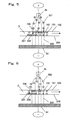
- a static eliminator as shown in Fig. 4 is known.
- the static eliminator 2 is disclosed in JP 2651476 C (hereinafter called document DS2).
- the static eliminator 2 consists of plural positive and negative ion-generating electrodes 2b connected with an AC power supply 2a and a planarly spread ion-attracting electrode 2d connected with an AC power supply 2c, and the positive and negative ion-generating electrodes 2b and the ion-attracting electrode 2d are installed to face each other through a traveling insulating sheet S.
- the positive and negative ion-generating electrodes 2b generate positive and negative ions, while high voltages opposite to the positive and negative ion-generating electrodes 2b in polarity are alternately applied to the ion-attracting electrode 2d, so that the positive and negative ions generated by the positive and negative ion-generating electrodes 2b can be attracted by the ion-attracting electrode 2d, to be forcibly irradiated to the sheet S.
- the toner powder is deposited on the sites where the apparent charge densities are high. That is, a site where no toner powder is deposited means a site where the sheet is apparently non-charged (where the apparent charge density is almost zero).
- the positive ions 301 generated by the positive and negative ion-generating electrode 2b are attracted near to the sheet S along the lines of electric force 500 generated by the positive and negative ion-generating electrode 2b and the ion-attracting electrode 2d, and are deposited on the first surface 100 of the sheet S, to positively charge the sheet S.
- the positive ions 301 are attracted more at the sites where the apparent charge densities are negative. That is, in the case where the positive charges 101 do not exist in the first surface 100 of the sheet S at the same sites in the in-plane direction of the sheet or in the case where even if the positive charges 101 exist, their quantity is smaller than the quantity of the negative charges 102 in the second surface 200 in the in-plane direction of the sheet, the positive ions 301 are attracted not only at the sites where only the negative charges 102 exist in the first surface 100 of the sheet S but also at the sites where the negative charges 202 exist in the second surface 200 of the sheet S.
- the negative ions 302 generated by the positive and negative ion-generating electrode 2b are attracted near to the sheet S along the lines of electric force 500 generated between the positive and negative ion-generating electrode 2b and the ion-attracting electrode 2d, and are deposited on the first surface 100 of the sheet S, to negatively charge the sheet S.
- the negative ions 302 are attracted selectively more to the sites than to their surroundings, for eliminating the positive charges. Also in this case, the negative ions 302 are attracted more at the sites where the apparent charge densities of sheet S are positive.
- the negative ions 302 are attracted not only at the sites where the positive charges 101 exist in the first surface 100 of the sheet S but also at the sites where the positive charges 201 exist in the second surface 200 of the sheet S.
- the irradiation quantities of positive and negative ions 301 and 302 depend, for example, on the capabilities of individual positive and negative ion-generating electrodes 2b and the phase of applied voltage, the total irradiation quantities of the positive and negative ions at the respective sites of the sheet S are different, and macroscopic positive and negative charge irregularity occurs in the sheet S (see Fig. 18 of document DS2).
- the macroscopic charge irregularity is the apparent charge irregularity and its state can be confirmed using a toner powder as apparent charges.
- the static eliminator 2 of document DS2 must include DC and AC static eliminating members 2e and 2f shown in Fig. 4.
- the macroscopic charge irregularity can be eliminated if such conditions as the applied voltage and installation positions of the DC and AC static eliminating members are optimized. If the sheet is wound without the DC and AC static eliminating members, the charges are so strong that discharge may occur on the sheet. Since the static eliminator 2 of document DS2 requires such DC and AC static eliminating members, the entire eliminator is large-sized and very costly, and it is difficult to add the eliminator to an existing sheet producing apparatus.
- Fig. 7 shows a case where such conditions as the voltage and arrangement of the DC and AC static eliminating members 2e and 2f are optimized and where the macroscopic positive and negative charge irregularity in the sheet is eliminated.
- the charges in the sheet S are balanced in both the surfaces, and the sheet S is apparently non-charged. However, in the respective surfaces of the sheet S, almost equal quantities of positive and negative charges remain.
- the reason why this occurs is that the positive and negative ion-generating electrodes 2b are disposed only on the side of the first surface 100 (top surface in Fig. 5) of the sheet S, and hence that at every moment during static elimination, the charges in the second surface 200 (bottom surface in Fig. 5) of the sheet S cannot be decreased. This phenomenon occurs also in the case where the DC and AC static eliminating members 2e and 2f are used. As a result, the charge densities in the first surface 100 of the sheet S can be eliminated only to such an extent that the charge densities balance the charge densities prevailing in the second surface 200 since before static elimination, i.e., to such an extent that the apparent charge densities become zero.
- the inventors measured, according to the method described later, the charge densities remaining in the respective surfaces of the sheet static eliminated by the conventional static eliminator 2.
- the charge densities at the static mark sites of the second surface 200 were virtually the same as those prevailing before static elimination, i.e., tens of microcoulombs per square meter to about 500 ⁇ C/m 2 in absolute value.
- the charge densities of the first surface 100 at the same sites (static mark sites) were almost equal to those of the second surface 200 in absolute value, though opposite in polarity, i.e., tens of microcoulombs per square meter to about 500 ⁇ C/m 2 in absolute value though opposite in polarity.
- the static elimination is achieved only to such an extent that the apparent charge densities (several microcoulombs per square meter to 10 ⁇ C/m 2 in absolute value) are made zero. So, it can be said that the static elimination effect is only up to less than 10% of the charge densities of the first surface 100. Rather, such a phenomenon was also confirmed that at a site where the charge density of the second surface 200 was larger than the charge density of the first surface 100 before static elimination in absolute value, the charge density of the first surface 100 increased to such a level that it became equal to the charge density of the second surface 200 after static elimination. It was found that the charges remaining in the first and second surfaces 100 and 200 were the causes of such defects as the irregularity of the coating material, static marks formed after film processing and sliding failure.
- This problem is an essential problem peculiar to the static elimination performed only from one surface of a sheet, and even if such conditions as the voltage and arrangement of the DC and AC static eliminating members 2e and 2f are optimized, the problem cannot be solved.
- the DC and AC static eliminating members 2e and 2f are provided only for making the macroscopic charge irregularity appear to be zero.
- two static eliminators of document DS2 can be installed in the sheet traveling direction, and the two sets, each consisting of the positive and negative ion-generating electrodes 2b and the ion-attracting electrode 2d, can be arranged at positions facing each other, with the sheet kept between the electrodes 2b and the electrode 2d, and with one set reversed to the other set in position, in order that the first surface 100 of the sheet is irradiated with ions, and subsequently that the second surface 200 of the sheet is irradiated with ions. Even in this case, there is no effect of decreasing the charges existing in the respective surfaces. The reason is that the static eliminator of document DS2 (static eliminator 2 shown in Fig.
- a static eliminator in which ion irradiation devices, each consisting of an ion-generating electrode and an ion-accelerating electrode disposed to face each other, are installed reversely to each other in position on the first surface 100 side and the second surface 200 side of an insulating sheet.
- This static eliminator is disclosed in JP 2002-313596 A (hereinafter called document DS3).
- the conventional static eliminator 3 includes an ion-generating electrode 3b connected with an AC power supply 3a and installed above the first surface 100 of a traveling insulating sheet S and an ion-accelerating electrode 3d connected with an AC power supply 3c and installed below the second surface 200 of the traveling insulating sheet S.
- the ion-generating electrode 3b and the ion-accelerating electrode 3d are installed to face each other with the insulating sheet S kept between them.
- an AC high voltage is applied to the ion-generating electrode 3b, to generate ions, and an AC high voltage opposite in polarity to the voltage applied to the ion-generating electrode 3b is applied to the ion-accelerating electrode 3d.
- the ions generated by the ion-generating electrode 3b are accelerated and attracted by the ion-accelerating electrode 3d, and as a result, the first surface 100 of the sheet S is forcibly irradiated with the ions.
- the static eliminator of document DS3 is basically equivalent to the case where two static eliminators of document DS2 described before (static eliminators 2 of Fig. 4) are disposed in the sheet traveling direction, to be reverse to each other in the static elimination side and the non-static elimination side. That is, even in the best mode, quantities of positive and negative ions necessary to make the apparent charge densities zero are merely supplied without greatly affecting the distributions of charge densities existing in the respective surfaces before start of static elimination.
- the potential is calculated to be in a range from -10 to -100 kV.
- This value range refers to a value range in the case where the electrostatic capacity of the sheet S placed in the space between the first ion-generating electrode 3b and the ion-accelerating electrode 3d is in a range from 10 to 100 pF.
- the Coulomb force 700 in the direction to shove away the negative ions 302 from the sheet S acts on the negative ions 302, and the negative ions 302 cannot sufficiently reach the sites of the sheet S where the positive charges 101 still exist. Also in the case where the second ion-generating electrode 3f generates the positive ions 301 to be irradiated to the second surface 200 of the sheet S, the same phenomenon occurs. As a result, the positive charges 101 of the first surface become excessive, and the positive ions 301 reaching the sheet S decrease.
- Ion irradiation devices each consisting of the ion-generating electrode 3b and the ion-accelerating electrode 3d facing each other, are arranged on both the surface sides of the sheet S, with the electrodes disposed alternately in reverse positions, and on the downstream side, two ion-generating electrodes are arranged to face each other on both the surface sides of the sheet S, one on the first surface 100 side and the other on the second surface 200 side.
- the ion-generating electrodes disposed downstream to face each other are disposed to eliminate the residual charges (same as the charges of macroscopic charge irregularities of static eliminator 2 of Fig. 4.)
- the dimensions and applied voltages of the ion-generating electrodes disposed downstream to face each other are not disclosed at all in document DS3.
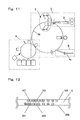
- a transfer sheet-carrying sheet and a transfer sheet (paper) static eliminator 4 of a copier shown in Fig. 11 is known.
- the static eliminator 4 is disclosed in JP 03-87885 A (hereinafter called document DS4) or JP 02-13977 A (hereinafter called document DS5).
- Fig. 11 is a drawing showing the copier shown in document DS4, as a whole.
- A indicates a section for forming a toner image onto a photosensitive drum
- B indicates a section for supplying a transfer sheet 4a
- C indicates a section for transferring a toner image onto the transfer sheet 4a on a transfer sheet-carrying sheet 4b wound around a transfer drum
- D indicates a section where the transfer sheet 4a having the toner image transferred from the transfer sheet-carrying sheet 4b is separated.
- the description of the details is not made here since it is not concerned with the present invention at all.
- wire corotron electrodes positioned outside as corona dischargers 4c and 4d and wire corotron electrodes positioned inside as corona dischargers 4e and 4f are installed to face each other on both sides of the transfer sheet 4a as a charged material and the transfer sheet-carrying sheet 4b.
- the first purpose of the static eliminator 4 is to more easily separate the transfer sheet 4a from the transfer sheet-carrying sheet 4b, and the second purpose is to initialize the potential of the transfer sheet-carrying sheet 4b.
- an AC voltage (500 Hz, 9.6 kV) is applied to the corona dischargers 4c and 4d, and a DC voltage (-4 kV) is applied as pulses to the corona discharger 4e, while a voltage different by 180° phase from that of the corona dischargers 4c and 4d is applied to the corona discharger 4f.
- the reason why a DC voltage is applied to the corona discharger 4e is that instead of superimpose a DC voltage as a bias on the AC voltage applied to the corona discharger 4f in opposite, it is intended to use two independent corona dischargers 4f and 4e.
- the average potentials of the transfer sheet 4a and the transfer sheet-carrying sheet 4b can be decreased. Since the transfer sheet 4a is positively charged in the previous step, a negative voltage is used as the DC voltage to allow easier separation of the transfer sheet-carrying sheet 4b. To achieve the second purpose, an AC voltage only is applied to the corona dischargers 4d and 4f. With regard to the charges of the transfer sheet-carrying sheet 4b, it is not necessary to eliminate the charges of both the outer surface and the inner surface. If the charges of the outer surface balance the charges of the inner surface to reduce the apparent potential to almost zero, the purpose can be achieved.
- the technique described in document DS4 is not intended to eliminate charges from a sheet having positively charged sites and negatively charged sites alternately formed at a small pitch in the same plane or a sheet having fine patterns with such sites existing together in both the surfaces. In the paper as a transfer sheet of a copier, such charge patterns are unlikely to be formed.
- the electric field between the top and bottom electrodes little has the capability of forcibly irradiating the sheet with ions.
- the positive and negative ions 301 and 302 generated by the corona dischargers 4d and 4f are mixed in the gap between the corona discharger 4d and the corona discharger 4f.
- the size of the gap is not clearly stated in document DS4, but according to other documents and the like relating to static eliminators of copiers, it is usually about 20 mm. According to document DS5, it is 22 mm.
- these static eliminators of copiers are very low in the capability of eliminating the charges of the respective surfaces of a sheet having positively charged sites and negatively charged sites alternately formed at a small pitch in the same plane or a sheet having such sites existing together on both the surfaces.
- the techniques can be applied in the case where the sheet traveling speed is as low as several to 10-odd m/min and can be applied to a transfer sheet or paper fromwhich it is not required to eliminate the fine charge patterns in either of the surfaces.
- the static elimination techniques cannot be applied as techniques for eliminating charges from an insulating sheet such as a film that travels at a high speed of about 50 to about 500 m/min and from which it is necessary to eliminate fine charge patterns in both the surfaces.
- the width of the transfer sheet or paper undergoing static elimination is about 500 mm at the largest, and it is not necessary to consider, for example, the vibration, strength and sagging of electrodes. For this reason, a high voltage is applied to wire electrodes extending in the in-plane direction perpendicular to the traveling direction of the sheet, for causing discharge to generate ions.
- a high voltage is applied to wire electrodes extending in the in-plane direction perpendicular to the traveling direction of the sheet, for causing discharge to generate ions.
- an insulating sheet such as a film undergoes static elimination
- its width is about 1 m at the smallest, and there is even an insulating sheet with a width of about 7 m.
- insulating sheets such as polyester films are used in many applications as magnetic recording materials, various photographic materials, insulating materials and various process materials, since they have excellent properties such as heat resistance, chemicals resistance and mechanical properties. For this reason, they are required to have surface properties suitable for respective applications, and they are covered with various materials.
- the sheets are thinly coated on their surfaces with a magnetic paint, ink-like paint, lubricating paint, releasing paint, or hard coating material, to form a coating layer.
- document DS6 states it is preferred that the surface potentials of the sheet are in a range from 0 to 80 V, and document DS7 states it is preferred that the surface potentials of the sheet are in a range from 0 to 2 kV.
- the surface potential refers to a value measured while the sheet is carried in air.
- this surface potential is called an aerial potential.
- the aerial potential relates to apparent charges (the apparent charge densities). Therefore, in the conventional techniques, the charge densities of the respective surfaces of a sheet are not taken into account at all.
- the visual field of a general electrostatic voltmeter used for measuring the aerial potential is usually a virtually circular area portion having a diameter of tens of millimeters to tens of centimeters, and the value of the measured potential is detected as an average value of potentials in the visual field.
- This matter is described in the catalogue (in Japanese) for Digital Low Potential Measuring Instrument KSD-0202 produced by Kasuga Electric Works Ltd (hereinafter called document DS8).
- document DS8 Digital Low Potential Measuring Instrument KSD-0202 produced by Kasuga Electric Works Ltd
- a coating process for example, when a die coater is used, the sheet travels, for example, with its second surface kept in contact with a backup roll.
- a coater roll is used to coat the first surface of the sheet. Since the sheet is kept in contact with the backup roll, stable traveling is assured to stabilize coating work, and a coating layer having uniform thickness can be formed.
- a metallic material is often used since the roll is required to be mechanically precise and to have durability such as wear resistance. Therefore, one surface of the sheet is kept in contact with the metallic surface of the backup roll, and the other surface is coated to have a coating film.
- An object of the invention is to solve the above-mentioned problems of the prior art by providing a static eliminator and a static eliminating method for easily eliminating the positively and negatively charged sites alternately formed at a small pitch in either surface or both the surfaces of a sheet.
- Another object of the invention is to provide a method for producing an insulating sheet liberated from the positively and negatively charged sites alternately formed at a small pitch in the surfaces of the sheet to such an extent that no problem occurs at least in the processing of the surfaces of the sheet or in the processed sheet, and also to provide an insulating sheet with such surface properties.
- the insulating sheet is coated with a coating material on a surface to form a coating layer, coating irregularity or repellent coating is hard to occur.
- a sheet having a metallic layer formed on a surface of the insulating sheet is hard to cause the problem of disarrangement of cut sheets.
- a static eliminator for an insulating sheet in which at least two static eliminating units are provided in the traveling path of an insulating sheet with an interval kept between them in the traveling direction of the sheet; each of the respective static eliminating units has a first electrode unit and a second electrode unit disposed to face each other through the sheet; the first electrode unit has a first ion-generating electrode and a first shield electrode having an opening near the pointed ends of the first ion-generating electrode; and the second electrode unit has a second ion-generating electrode and a second shield electrode having an opening near the pointed ends of the second ion-generating electrode, characterized in that at each of the respective static eliminating units,
- the voltages applied to the first ion-generating electrodes of the respective static eliminating units and the voltages applied to the second ion-generating electrodes of the respective static eliminating units are supplied from respective single AC power supplies, or from respective groups of plural AC power supplies synchronous with each other in the group with a zero or predetermined potential difference.
- This static eliminator is called a second static eliminator.
- the first static eliminator it is preferable that the first ion-generating electrode and the second ion-generating electrode of each of the respective static eliminating units are arrays of needle electrodes.
- This static eliminator is called a third static eliminator.
- the first shield electrode comprises a first rear shield electrode disposed on the rear side of the first ion-generating electrode
- the second shield electrode comprises a second rear shield electrode disposed on the rear side of the second ion-generating electrode.
- This static eliminator is called a fourth static eliminator.
- a first insulating member is provided between the first ion-generating electrode and the first rear shield electrode, and/or in the second shield electrode, a second insulating member is provided between the second ion-generating electrode and the second rear shield electrode.
- This static eliminator is called a fifth static eliminator.
- the first static eliminator it is preferable that at each position in the width direction of the sheet, at any two adjacent static eliminating units, if the static eliminating unit interval between the middle point of the line segment connecting the pointed end of the first ion-generating electrode with the corresponding pointed end of the second ion-generating electrode of one of the two adjacent static eliminating units, and the corresponding middle point of the other static eliminating unit in the traveling direction of the sheet is d 2 (in mm) , the following formula (II) d 2 ⁇ 12 x d 1 2 /(d 3 x d 4 ) is satisfied.
- This static eliminator is called a sixth static eliminator.
- a static eliminator for an insulating sheet in which at least two static eliminating units are provided in relation with a virtual plane, with an interval kept between them in a predetermined direction along the virtual plane; each of the static eliminating units has a first electrode unit and a second electrode unit disposed to face each other through the plane; the first electrode unit has a first ion-generating electrode and a first shield electrode having an opening near the pointed ends of the first ion-generating electrode; and the second electrode unit has a second ion-generating electrode and a second shield electrode having an opening near the pointed ends of the second ion-generating electrode, characterized in that at each of the static eliminating units, the first ion-generating electrode and the second ion-generating electrode are disposed to face each other through the plane substantially symmetrically with the virtual plane, and the voltage applied to the first ion-generating electrode and the voltage applied to the second ion-generating electrode are substantially opposite to each other in polarity.
- This static eliminator is called a seventh
- a static eliminating method for an insulating sheet comprising the step of simultaneously irradiating the first surface and the second surface of an insulating sheet with respective monopolar ion clouds substantially opposite to each other in polarity at respective sites of the sheet, and the step of simultaneously irradiating the first and second surfaces with respective monopolar ion clouds reverse in polarity to those applied before at said site of the sheet.
- This static eliminating method is called a first static eliminating method.
- a static eliminating method for an insulating sheet in which the first surface of an insulating sheet is irradiated with a monopolar first ion cloud reversing in polarity with the lapse of time while the sheet travels, and the second surface of the sheet is irradiated with a monopolar second ion cloud reversing in polarity with the lapse of time, but substantially opposite in polarity to the first ion cloud, simultaneously with the first ion cloud, characterized in that the first and second ion clouds are reversed in polarity so that while respective sites of the sheet in the traveling direction pass through the region irradiated with the first and second ion clouds, the first and second ion clouds are reversed in polarity once or more.
- This static eliminating method is called a second static eliminating method.
- a static eliminating method for an insulating sheet in which the first surface and the second surface of an insulating sheet are simultaneously irradiated with a pair of monopolar ion clouds substantially opposite to each other in polarity by a predetermined number of times, while the sheet travels, characterized in that the pair of ion clouds are applied so that the respective numbers of times of irradiating the first and second surfaces with a positive ion cloud and a negative ion cloud are not less than 1/4 of said predetermined number of times at respective sites of the sheet.
- This static eliminating method is called a third static eliminating method.
- a static eliminating method for an insulating sheet in which the first surface of an insulating sheet is irradiated with a group of first monopolar ion clouds smoothly reversing in polarity with the lapse of time, and the second surface of the sheet is simultaneously irradiated with a group of second monopolar ion clouds smoothly reversing in polarity with the lapse of time but substantially opposite in polarity to the first group of ion clouds, characterized in that in sites of 2/3 or more at all the sites in the traveling direction of the sheet, the respective groups of ion clouds are irradiated in such a manner that the polarity of the ion clouds corresponding to 1/4 or more of the ion clouds in each of the first and second groups of ion clouds can be opposite to the polarity of the other ion clouds in the group.
- This static eliminating method is called a fourth static eliminating method.
- a static eliminating method for an insulating sheet in which an insulating sheet is made to travel between the first and second ion-generating electrodes of the respective static eliminating units in the static eliminator for an insulating sheet as set forth in claim 6, while both the surfaces of the sheet are irradiated with the positive and negative ions generated from the first and second ion-generating electrodes, characterized in that where respective AC voltages of the same phase are applied to the first and second ion-generating electrodes of the respective static eliminating units, and if the frequency of the AC voltages is f (in Hz) and an effective value of the potential difference between the first and second ion-generating electrodes is 2V (in V) , then the following formulae (III) and (IV) 90d 1 ⁇ V ⁇ 530d 1 0.0425 x d 1 2 x f ⁇ V ⁇ 0.085 x d 1 2 x f are satisfied.
- This static eliminating method is called a fifth static eliminating method.
- the traveling speed of the sheet is u (in mm/sec) and at each position in the width direction of the sheet, the interval between the middle point of the line segment connecting the pointed end of the first ion-generating electrode with the corresponding pointed end of the second ion-generating electrode of the most upstream static eliminating unit, and the corresponding middle point of the most downstream static eliminating unit in the traveling direction of the sheet, i.e., the sum of all the static eliminating unit intervals d 2 from the most upstream static eliminating unit to the most downstream static eliminating unit is D 2 (in mm) , the following formula (V) D 2 > u/f is satisfied.
- This static eliminating method is called a sixth static eliminating method.
- the fifth static eliminating method it is preferable that at sites of 2/3 or more of all the sites in the traveling direction of the sheet, said AC voltages are applied to the respective first and second ion-generating electrodes of n static eliminating units, where n is the total number of static eliminating units, in such a manner that the polarity of the potentials of the ion-generating electrodes of static eliminating units as many as not smaller than the number obtained from formula (n - 0.0006/d f )/2 ⁇ where d f (in m) is the thickness of the sheet ⁇ and not smaller than 0, said potentials working while the each of said sites passes directly under the ion-generating electrodes of said specified number of static eliminating units, can be opposite to the polarity of the potentials of the other ion-generating electrodes of the static eliminating units concerned, said potentials working while the said portion passes directly under the ion-generating electrodes of the other static eliminating units.
- This static eliminating method is called a seventh static eliminating method.
- a static eliminating method for an insulating sheet in which while an insulating sheet is made to travel between the first and second ion-generating electrodes of the respective static eliminating units in the static eliminator for an insulating sheet as set forth in claim 1, both the surfaces of the sheet are irradiated with the positive and negative ions generated from the first and second ion-generating electrodes of the respective static eliminating units, characterized in that in the case where a voltage is applied to each of the respective first and second ion-generating electrodes of the respective static eliminating units, if the frequency of the voltage is f (in Hz) and the one-side peak voltage is Vp (in V), then the following formulae (VI) and (VII) 130 x d 1 ⁇ Vp ⁇ 750 x d 1 0.120 x d 1 2 x f ⁇ Vp are satisfied and the voltage is applied to each of the respective ion-generating electrodes in such a manner that in the case where a portion of the
- a static eliminating method for an insulating sheet in which while an insulating sheet is made to travel between the first and second ion-generating electrodes of the respective static eliminating units in the first static eliminator, both the surfaces of the sheet are irradiated with the positive and negative ions generated from the first and second ion-generating electrodes of the respective static eliminating units, characterized in that in the case where AC voltages smoothly changing in polarity are applied to the respective first and second ion-generating electrodes of the respective static eliminating units, if the frequency of the AC voltages is f (in Hz) and an effective value of the potential difference between the first and second ion-generating electrodes is 2V (in V) , then the following formulae (VIII) and (IX) 90 x d 1 ⁇ V ⁇ 530 x d 1 0.085 x d 1 2 x f ⁇ V are satisfied and in the case where a portion of 2/3 or more is considered in the traveling direction of the
- a static eliminating method for an insulating sheet in which while an insulating sheet is made to travel between the first and second ion-generating electrodes of the respective static eliminating units in the first static eliminator, both the surfaces of the sheet are irradiated with the positive and negative ions generated from the first and second ion-generating electrodes of the respective static eliminating units, characterized in that where AC voltages smoothly changing in polarity are applied to the respective first and second ion-generating electrodes of the respective static eliminating units, if the frequency of the AC voltages is f (in Hz) and an effective value of the potential difference between the first and second ion-generating electrodes is 2V (in V) , then the following formulae (X) and (XI) 90 x d 1 ⁇ V ⁇ 530 x d 1 0.085 x d 1 2 x f ⁇ V are satisfied and in the case where a portion of 2/3 or more is considered in the traveling direction of the sheet, the AC
- the any eliminating unit intervals d 2 is constant value d 20 (in mm)
- a static eliminating method for an insulating sheet characterized in that in the predetermined period of starting and/or ending the traveling of an insulating sheet, the second or fifth static eliminating method is used for eliminating charges from the sheet, and in the steady traveling state of the sheet, the third, fourth, ninth or tenth static eliminating method is used for eliminating charges from the sheet.
- This static eliminating method is called a twelfth static eliminating method.
- any one of the first through fifth, eighth and tenth static eliminating method it is preferable static elimination is carried out so that the rear side equilibrium potentials of the first surface and the rear side equilibrium potentials of the second surface at the respective sites in the plane of the insulating sheet may be respectively in a range from -340 V to 340 V.
- This static eliminating method is called a fourteenth static eliminating method.
- the fourteenth static eliminating method it is preferable static elimination is carried out so that the rear side equilibrium potentials of the first surface and the rear side equilibrium potentials of the second surface may be respectively in a range from -200 V to 200 V.
- This static eliminating method is called a fifteenth static eliminating method.
- a method for producing a charge-eliminated insulating sheet comprising the step of eliminating charges from an insulating sheet by any one of the first through fifth, eighth, ninth and tenth static eliminating method.
- a charge-eliminated insulating sheet characterized in that both the charge densities of the first surface of the sheet and the charge densities of the second surface change smoothly cyclically in the longitudinal direction of the sheet; the amplitudes in the change of the respective charge densities are in a range from 1 to 150 ⁇ C/m 2 ; and the charges of the first surface and the charges of the second surface at respective sites in the in-plane direction of the sheet are opposite to each other in polarity.
- This sheer is called a first sheet.
- the amplitudes are in a range from 2 to 30 ⁇ C/m 2 .
- This sheet is called a second sheet.
- both the charge densities of the first surface and the charge densities of the second surface change in cycles of 10 to 100 mm.
- This sheet is called a third sheet.
- a charge-eliminated insulating sheet characterized in that the rear side equilibrium potentials of the first surface and the rear side equilibrium potentials of the second surface at respective sites of an insulating sheet are respectively in a range from -340 V to 340 V, and that the charges of the first surface and the charges of the second surface at respective sites in the in-plane direction of the sheet are opposite to each other in polarity.
- This sheet is called a fourth sheet.
- the rear side equilibrium potentials of the first surface and the rear side equilibrium potentials of the second surface are respectively in a range from -200 V to 200 V.
- This sheet is called a fifth sheet.
- the sums of the charge densities of the first surface and the charge densities of the second surface at respective sites in the in-plane direction of the sheet, i.e., apparent charge densities at respective sites of the sheet, are in a range from -2 to 2 ⁇ C/m 2 .
- This sheet is called a sixth sheet.
- the sums of the charge densities of the first surface and the charge densities of the second surface at respective sites in the in-plane direction of the sheet, i.e., apparent charge densities at respective sites of the sheet, are in a range from -2 to 2 ⁇ C/m 2 .
- This sheet is called a seventh sheet.
- the insulating sheet include a plastic film, fabric and paper.
- the sheet can be fed from a long sheet wound as a roll or sheet by sheet.
- the plastic film include a polyethylene terephthalate film, polyethylene naphthalate film, polypropylene film, polystyrene film, polycarbonate film, polyimide film, polyphenylene sulfide film, nylon film, aramid film, polyethylene film, etc.
- a plastic film has high insulation performance compared with sheets of other materials.
- the static elimination technique provided by the invention can be effectively used for eliminating charges from a plastic film, especially for eliminating the positively and negatively charged sites alternately formed at a small pitch in the surfaces of the film.
- the traveling path of an insulating sheet means a space through which the insulating sheet passes for being liberated from charges.
- the direction normal to an insulating sheet means the direction normal to the plane free from sagging in the width direction, which plane is assumed to be the insulating sheet traveling in the traveling path.
- the virtual plane means a predetermined plane virtually assumed between first and second ion-generating electrodes.
- the insulating sheet traveling in the traveling path is assumed to be a plane free from sagging in the width direction, and where the position of the insulating sheet in the direction normal to the sheet varies with the traveling of the sheet, it can happen that the plane of the sheet assumed to be in the temporally averaged position agrees with the virtual plane.
- the width direction means the direction corresponding to the in-plane direction of the virtual plane, perpendicular to the traveling direction of the insulating sheet or perpendicular to the direction of predetermined row direction of disposed static eliminating units.
- the pointed end of ion-generating electrode means the region that forms an electric field capable of generating ions, among respective portions of the ion-generating electrode and that is nearest to the virtual plane.
- the ion-generating electrode is often extended in the width direction.
- “the pointed ends” are determined at the respective positions in the width direction.
- the regions among the wire nearest to the virtual plane at the respective positions in the width direction correspond the regions.
- the ion-generating electrode is an array of needle electrodes installed at predetermined intervals in the width direction and extending in the direction normal to the insulating sheet, the region among respective portions of the respective needle nearest to the virtual plane (the tips of the respective needle electrodes) correspond to the regions at those position in the width direction.
- the pointed ends of the ion-generating electrodes are defined at the respective positions on a polygonal line 5dL connecting the respective tips of the needle electrodes provided at predetermined intervals in the width direction as shown in Fig. 18A.
- the polygonal line 5dL is called the virtual line of the pointed ends of the ion-generating electrodes.
- the positions on the virtual line of the pointed ends of the ion-generating electrodes agree with the tips of the needle electrodes.
- the average position of the pointed ends of the two or more ion-generating electrodes at each position in the width direction is considered as the pointed end of the ion-generating electrode at the position in the width direction.
- a shield electrode between the position of the feet of the perpendiculars from the pointed end of the first ion-generating electrode to the plane including the position of the pointed end of the second ion-generating electrode and parallel to the virtual plane, and the position of the pointed end of the second ion-generating electrode.
- ions mean various charge carriers such as electrons, atoms gaining or losing electrons, molecules having charges, molecular clusters and suspended particles.
- an ion cloud means a group of ions generated by ion-generating electrode, which spreads and floats in a certain space like a cloud without staying in a specific place.
- a monopolar ion cloud means an ion cloud in which the quantity of positive or negative ions is overwhelmingly larger the quantity of the ions opposite in polarity.
- a positive monopolar ion cloud is formed near the ion-generating electrode, and when ion-generating electrode is negative in potential, a negative monopolar ion cloud is formed near the ion-generating electrode.
- the polarity of the voltage of the ion-generating electrode is reversed twice or more till the ions generated near the ion-generating electrode reach the insulating sheet, there occurs such a phenomenon that positive and negative ions exist together between the ion-generating electrode and the insulating sheet.
- the positive and negative ions are recombined with each other to lower the concentrations of ions, and whenever the polarity is reversed, the direction of Coulomb force to the ions is also reversed. As a result, the ion cloud irradiated to the insulating sheet cannot be monopolar any more.
- an ion-generating electrode means an electrode capable of generating ions in the air near the pointed ends of the electrode due to, for example, the corona discharge caused by application of a high voltage.
- a shield electrode means an electrode disposed near ion-generating electrode, to give an adequate potential difference between the shield electrode and the ion-generating electrode, for assisting the corona discharge at the pointed ends of the ion-generating electrode.
- first and second ion-generating electrodes are disposed to face each other substantially symmetrically with virtual plane
- first and second ion-generating electrodes face each other through the virtual plane and that at each position in the width direction, the distance between the positions of the feet of the perpendiculars from the pointed ends of the first and second ion-generating electrodes to the virtual plane is shorter than the distance between the positions of the feet of the perpendicular from the pointed end of the first ion-generating electrode and the second shield electrode to the virtual plane, and also shorter than the distance between the positions of the feet of the perpendiculars from the pointed end of the second ion-generating electrode and the first shield electrode to the virtual plane.
- a charge pattern means a state where at least a part of the insulating sheet is locally positively and/or negatively charged. This state can be referred to a pattern formed by a fine powder (toner) or the like owing to the charged state by the method disclosed, for example, in JP 09-119956 A (hereinafter called document DS9) or JP 2001-59033 A (hereinafter called DS10).
- "apparent charge density” means the sum of the local charge density of both the surfaces at the same site in the in-plane direction of insulating sheet.
- the local charge density means the charge density of circular area portion having a diameter about 6 mm or less, more preferably a diameter 2 mm or less.
- being apparently non-charged means a state where the apparent charge densities at respective sites in the in-plane direction of an insulating sheet are substantially zero (-2 to 2 ⁇ C/m 2 ).
- charges are apparently eliminated means a state where sites of a sheet substantially non-zero (less than -2 ⁇ C/m 2 or more than +2 ⁇ C/m 2 ) in the apparent charge densities are made apparently non-charged by means of static elimination.
- the rear side equilibrium potential of the first surface of an insulating sheet means the potential of the first surface measured when the measuring probe of a electrostatic voltmeter is sufficiently kept as close as keeping a clearance of about 0.5 to about 2 mm to the first surface in such a condition that a grounded conductor is kept in contact with the second surface to induce the charges in the grounded conductor to ensure that the potential of the second surface may be substantially kept at zero.
- the measuring probe of the electrostatic voltmeter has as small as less than two millimeters in the diameter of the opening for measurement.
- the probe can be, for example, probe 1017 (opening diameter 1.75 mm) or 1017EH (opening diameter 0.5 mm) produced by Monroe Electronics, Inc.
- keeping the rear surface (second surface) of the insulating sheet in contact with a grounded conductor means that both of them are kept in tight contact with each other in such a state that there is no clear air layer between the insulating sheet and the metallic roll.
- This state means that the thickness of the air layer remaining between both of them is 20% or less of the thickness of the sheet and 10 ⁇ m or less.
- either the probe of the electrostatic voltmeter or the sheet having the grounded conductor kept in contact with its rear surface (second surface) is made to travel at a low speed (about 5 mm/sec) using a moving means capable of being adjusted in position such as an XY stage, to measure the rear side equilibrium potential one after another, and the obtained data are one-dimensionally or two-dimensionally mapped.
- the rear side equilibrium potential of the second surface can also be measured similarly.
- each potential is a potential from a grounded point, unless otherwise stated.
- synchronization means that the respective static eliminating unit intervals of two adjacent static eliminating units are integer times of the traveling distance of the insulating sheet per one cycle of the applied AC voltage.
- superimposition means that at a certain site of the insulating sheet, the ions irradiated by respective static eliminating units are superimposed.
- synchronous superimposition means that all the static eliminating unit intervals are integer times of the traveling distance of an insulating sheet per cycle of the applied AC voltage.
- all the ion-generating electrodes on one side generate ions of the same polarity, and charges of the same polarity are superimposed at the site.
- synchronous superimposition intensity expresses the intensity of polar concentrated degree of the ion clouds irradiated from respective static eliminating units to respective site of an insulating sheet, as a relative value with the value in the case of synchronous superimposition as one.
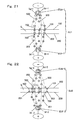
- parameters d 0 , d 1 , d 2 , d 3 , d 4 , and D 2 expressing the positional relations of the respective electrodes and respective static eliminating units are defined as each position in the width direction as shown in Figs. 17, 18A and 18B.
- the first static eliminating unit is shown as the typical unit.
- suffix is used as symbol for distinguishing the positions of the static eliminating units.
- Suffix "1" in Fig. 18A and 18B signifies that that belongs to the first static eliminating unit.
- symbol d is used, and to express the ion-generating electrode facing the second surface of the sheet, symbol f is used.
- symbol g is used, and to express the shield electrode facing the second surface of the sheet, symbol h is used.
- electrode discrepancy d 0 -1 of first static eliminating unit means a gap between the pointed end of the first ion-generating electrode 5d-1 and the pointed end of the second ion-generating electrode 5f-1 in the traveling direction of the sheet.
- normal direction inter-electrode distance d 1 -1 of first static eliminating unit means the distance between the pointed end of the first ion-generating electrode 5d-1 and the pointed end of the second ion-generating electrode 5f-1 in the direction normal to the insulating sheet.
- static eliminating unit interval d 2 -1 means the interval between the middle point 5x-1 of the line segment connecting the pointed end of the first ion-generating electrode 5d-1 of first static eliminating unit with the pointed end of the second ion-generating electrode 5f-1 of first static eliminating unit, and the middle point 5x-2 (not shown in the drawing) of the line segment connecting the pointed end of the first ion-generating electrode 5d-2 (not shown in the drawing) of the static eliminating unit adjacent to said static eliminating unit (second static eliminating unit) with the pointed end of the second ion-generating electrode 5f-2 (not shown in the drawing) of the static eliminating unit adjacent to said static eliminating unit (second static eliminating unit) , in the traveling direction of the sheet.
- the normal direction inter-shield-electrode distance d 3 -1 of first static eliminating unit means the shortest distance between the first shield electrode 5g-1 and the second shield electrode 5h-1 in the direction normal to the sheet.
- the average value (d 3l- 1 + d 3r- 1)/2 between the upstream shortest distance d 3l- 1 and the downstream shortest distance d 3r- 1 is used as the "normal direction inter-shield-electrode distance d 3 -1".
- shield electrode opening width d 4 -1 of first static eliminating unit means the opening width of the first and second shield electrodes in the traveling direction of the sheet.
- the average value (d 41- 1 + d 42- 1)/2 of them is used as the "shield electrode opening width d 4 -1".
- static eliminating gate length D 2 means the distance between the middle point 5x-1 of the line segment connecting the pointed ends of the first and second ion-generating electrodes 5d-1 and 5f-1 of the most upstream static eliminating unit (the first static eliminating unit) and the middle point 5x-n of the of the line segment connecting the pointed ends of the first and second ion-generating electrodes 5d-n and 5f-n of the most downstream (n-th) static eliminating unit in the traveling direction of the sheet.
- an insulating sheet having positively and negatively charged sites alternately formed at a small pitch in the same plane or having such charged sites existing together in both the surfaces can be balanced between positive and negative charges and can be liberated from charges in both the surfaces substantially to a harmless level.
- an insulating sheet made apparently non-charged but also an insulating sheet made substantially non-charged can be produced by a very simple static eliminating method and eliminator.
- the static charges can be effectively eliminated, and charge patterns can be eliminated.
- the insulating sheet produced by the static eliminator or the static eliminating method of the invention, or the insulating sheet of the invention in post-process such disadvantages as vacuum evaporation failure or coating irregularities are hard to occur, since the insulating sheet has few locally strongly charged portions such as static marks.
- corona discharger 4d ... corona discharger 4e ... corona discharger 4f ... corona discharger 5 ... static eliminator 5a ... guide roll 5b ... guide roll 5c ... first AC power supply 5d ... first ion-generating electrode 5e ... second AC power supply 5f ... second ion-generating electrode 5g ... first shield electrode 5h ... second shield electrode 5i ... insulating component 5j ... insulating component 5k ... vertical direction 51 ...traveling direction of insulating sheet 6 ... core 7 ... discharge electrode 7a ... ion-generating electrode 7b ... shield electrode 7c ... high voltage core wire 7d ... insulating component 8 ... discharge electrode 8a ...
- ion-generating electrode 8b ... shield electrode 8c ... high voltage core wire 8d ... insulating component 10 ... support of electric conductor 12 ... coated surface 13 ... die head coating section 14 ... backup roll 15 ... carrier roll 16 ... die 100 ... first surface (of sheet) 200 ... second surface (of sheet) 101 ... positive charge (of first surface of sheet) 102 ... negative charge (of first surface of sheet) 201 ... positive charge (of second surface of sheet) 202 ... negative charge (of second surface of sheet) 301 ... positive ion 302 ... negative ion 400 ... induced charge 500 ... line of electric force 700 ... Coulomb force S ... sheet ⁇ ... angle formed between 5k and 5l
- the existence of charges in the first surface 100 of a film can be confirmed, for example, according to the following methods.
- the existence of charges in the second surface 200 can also be confirmed similarly, as a matter of course.
- the second surface 200 of a film is kept in contact with a conductor, and in this state, a toner powder is sprinkled over the first surface 100.
- the conductor can be used a metallic plate, metallic roll, etc.
- a toner powder is sprinkled, the film is destroyed.
- As the toner powder a negative toner powder only can be used, but positive and negative toners with respective colors can also be used.
- the first charge neutralization method is to form a conductive film on the second surface 200, for example, by vacuum evaporation.
- the second neutralization method the first surface 100 of the film is kept in contact with a conductor, and in this state, the second surface 200 is coated with a polar solvent. The coated surface is then dried to neutralize only the charges of the second surface 200.
- the charged state of a film can be identified simply and quickly in an atmosphere of room temperature and atmospheric pressure.
- This method is recommended since the sensitivity of the toner to be deposited on the surface having charges is high.
- Polar solvents easy to handle and quick to dry include ethanol, isopropyl alcohol, etc. It is preferred that a polar solvent is coated as if wiping using cloth or the like and then is dried.
- the film having a conductive material such as a metal vapor-deposited can be used as it is as a sample for evaluating the charged state of the non-vapor-deposited surface.
- a negative toner powder or positive and negative toners with respective colors can be used.
- the inventors confirmed charged states of films using these methods for identifying the charged states of films, and examined mechanisms working in such problems that when a film is coated with a coating material, coating irregularity occurs, that a coating material is partially repelled without being deposited in some places, and that when plural films are overlaid, the edges of the films cannot be neatly arranged due to cling films together (disarrangement of overlaid films). As a result, they found a preferred charged state of the film capable of obviating the problems otherwise caused by charges in the post-processes. Modes of charged states of films are described below.
- the state the charges in both the surfaces of a film balance (almost same in quantities, polarities opposite) each other, and the film is in an apparently non-charged. That is, the state, in the evaluation of charge densities by the first confirmation method, the sums of the charge densities of both the surfaces at the respective sites in the in-plane direction (apparent charge density in the respective sites) of a film are in a range from - 2 to +2 ⁇ C/m 2 , or the toner powder is not deposited.
- the charge densities existing in the respective surfaces of a film are sufficiently small.
- the state, the evaluation of charge densities by the first confirmation method the charge densities of the respective surfaces of the film are respectively in a range from -150 to + 150 ⁇ C/m 2 .
- it is preferable that the charge densities of the respective surfaces of the film are respectively in a range from - 30 to +30 ⁇ C/m 2 .
- This state is defined to be “substantially non-charged.”
- the charge densities existing in the respective surfaces of a film are sufficiently small, and when the film is kept in tight contact with a conductor, the potentials of the surface not kept in contact with the conductor, i.e., rear side equilibrium potentials in a range from -340 to 340 V in this state.
- a conductive material is formed on one surface of a film in post-processing, for example, by vacuum evaporation or bonding of a metallic foil such as an aluminum foil
- the film is only required to satisfy the modes A and B, though depending on the post-processing of the film.
- disarrangement of overlaid films can occur.
- the Coulomb force proportional to the quantity of charges in the surface not having a conductive film affects the disarrangement of overlaid films (slipperiness). Therefore, it is preferred to control the charged state of the film by means of charge densities.
- a film with a thickness of about 1 ⁇ m to about 60 ⁇ m is only required to satisfy the modes A and B. If the film is thicker than the range, it is preferred to satisfy the rear side equilibrium potentials of mode C, instead of mode B. The reason is that both the apparent charges of the film and the rear side equilibrium potentials of the coated surface caused by the charge densities of the coated surface affect the coating irregularity defect. Also for inhibiting other defects, it is preferred to satisfy the modes B and C.
- the first mode of coating irregularity defects is the first mode of coating irregularity defects
- the apparent charge densities in absolute value of the film S are large in this mode.
- the apparent charge densities are less than -2 ⁇ C/m 2 or more than +2 ⁇ C/m 2 , and the film is apparently charged.
- the coating irregularity of this mode occurs when the film is held in air.
- the rear side equilibrium potentials of the coated surface of the film S are large in absolute value in this mode.
- the rear side equilibrium potentials are less than - 340 V or more than +340V.
- the coating irregularity of this mode occurs above a conductive backup roll.
- the electric field formed between respectively adjacent positive and negative charges is slightly formed near outside the coating surface, but the influence of the electric field on the applied coating solution is small.
- the reason is that the distances between positive and negative charges existing in the respective surfaces of the film are small.
- the distances correspond to the thickness of the film and are in a range from several micrometers to hundreds of micrometers at the longest.
- the electric field is closed in the film, and a strong electric field does not work near outside the coating surface.
- an electric field in the in-plane direction of the film works near outside the coated surface.
- this electric field is in a very limited microscopic region, i.e., a region of several micrometers to hundreds of micrometers at the largest, and the migration area of the coating solution is very small. Furthermore, the quantity of the solution capable of migrating in proportion to the region is also very slight. So, even if irregularity occurs, the irregularity cannot be visually observed. This explanation is concerning the relation between charges and coating irregularity in the case where a film held in air is coated.
- a film can be coated while it is held in air
- a film can also be coated while it travels on a roll.
- the roll can be, for example, a backup roll of a die head coater, or a carrier roll for changing the traveling direction of the film.
- apparent charge density is zero, that is, if the film is the film S as shown in Fig. 7, there is a large problem that coating irregularity defects of the second mode occur. The mechanism in which the coating irregularity of this mode occurs is described below in detail.
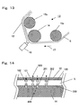
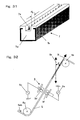
- Fig. 13 is a schematic drawing showing a part of the coating process using a die head coater.
- the film S is continuously unwound from a film package (not shown in the drawing) wound up as a roll and reaches a coating section 13.
- the coating section 13 is provided with two carrier rolls 15a and 15b, a backup roll 14 positioned between them, and a die head 16.
- the film S reaching the coating section 13 travels in contact with the carrier roll 15a, the backup roll 14 and the carrier roll 15b, in the direction indicated by the arrow 17, being changed in traveling direction.
- the coating solution put out from the die head 16 is applied to the film S, to form the coating surface 12 formed by coating layer on the film S.
- the film S coated with the coating solution gets the solvent of the coating solution evaporated and dried in a drying section (not shown in the drawing) , and finally wound as a roll in a winding section (not illustrated) .
- the film S is coated with a predetermined coating material (coating solution) put out from the die head 16.
- the backup roll 14 is installed for allowing the film S to travel stably and for keeping the clearance between the film S and the die head 16 constant.
- the backup roll 14 is, for example, a metallic roll plated with hard chromium, or a metallic roll covered with an elastic substance. As the elastic substance, a conductive rubber is often used.
- the conductive rubber is used for the purpose of preventing the electrification of the backup roll 14, and prevents the firing of the organic solvent by electrostatic discharge.
- the backup roll 14 is made of a conductive material in most cases. Furthermore, in other coating methods using a roll coater or gravure coater, similarly a backup roll is often used.
- the charged state of the film S on the conductive roll is as shown in Fig. 14.
- Fig. 14 in the state where the film S is kept in contact with the conductive backup roll 14, the second surface 200 of the film S is kept in contact with the conductor, and the first surface 100 is on the coater side (die head 16 side) and becomes the surface coat with the coating solution (hereinafter called the coated surface 12).
- the coated surface 12 in response to the positive charges 201 and the negative charges 202 of the second surface 200, charges 400 of opposite polarity are induced in the backup roll 14. As a result, the potentials of the second surface 200 become zero.
- the positive charges 101 and the negative charges 102 of the first surface 100 as the coated surface 12 cannot induce sufficient charges 400 in the backup roll 14, because of the distance corresponding to the thickness of the film S from the surface of the backup roll 14. As a result, the charges of the first surface 100 actively exist. As a result, in the coating surface 12, the positive and negative charges 101 and 102 of the first surface 100 form an electric field. Because of the phenomenon in which the charges actively exist, even if the apparent charge density of film is zero, the electric field acts on the applied coating solution, causing coating irregularity.
- the above description covers a phenomenon on the backup roll 14 of a die head coater, but also in the following case, an electric field acts on an applied coating solution in a similar mechanism. That is, a film S uniformly coated with a coating solution is carried into a drying step for evaporating and drying the solvent contained in the coating solution. In this case, it is practiced that the film S coated with the coating solution not yet dried is passed on the surface of a metallic roll, or that for better thermal conduction to the film S, the film is kept in contact with a metallic roll for drying. Even on the metallic roll, the same phenomenon as occurring in the case of the backup roll 14 occurs, and coating irregularity occurs in the film S.
- the coating solution cannot be charged, the migration of the coating solution occurs due to dielectrophoresis, and the coating solution is collected in a site of the film with a strong electric field, and the thickness of the coating layer in the portion becomes larger than the thickness of the coating layer in the surrounding, to cause coating irregularity.
- the electric field intensity near outside the first surface 100 in the direction normal to the film S is proportional to the rear side equilibrium potentials. That is, it is proportional to the distance between the conductor (metallic plate) and the first surface 100, in other words, the thickness of the film S.
- the rear side equilibrium potentials of thin film S are small compared with those of a thick film S since the distance from the conductor is very short. That is, the electric field intensity in the normal direction is small.
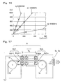
- Fig. 15A of the film S having a thickness d f1 and charges shown at the top, the graph (a) showing the charge densities (in ⁇ C/m 2 ) of the first surface 100 at the middle, and the graph (b) showing the rear side equilibrium potentials (in V) at the bottom.
- Fig. 15B of the film S having a thickness d f2 and charges shown at the top, the graph (a) showing the charge densities (in ⁇ C/m 2 ) of the first surface 100 is shown at the middle, and the graph (b) showing the rear side equilibrium potentials (in V) is shown at the bottom.
- the rear side equilibrium potential (in V) depends on the thickness of the film, that is, when the thickness of the film is d f2 > d f1 ,, the absolute value of the rear side equilibrium potential of the thickness of the film d f2 becomes larger than that of d f1 even if the absolute value of the charge density is small.
- Concerning whether or not coating irregularity occurs it is important how large the charges of the first surface 100 as the coated surface 12 of the film S are as "the absolute value of the rear side equilibrium potentials," and the magnitude of "the absolute value of the rear side equilibrium potential" depends on the quantity of charges of the film S and the thickness of the film S. That is, if the absolute value of the rear side equilibrium potential shown in the respective graphs (b) of Figs. 15A and 15B becomes large, coating irregularity occurs.
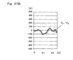
- the intensities of charges at which coating irregularity occurred were experimentally measured, and the results are shown in Fig. 16.
- the film S used here was a film, on the first surface 100 of which positively and negatively charged zones were alternately formed in stripes.
- the positive and negative zones in the film S are formed in cycles of about 25 mm, and the absolute value of the rear side equilibrium potentials are highest in the central portions in the respective positively and negatively charged zones, and show a gentle sinusoidal wave distribution in the direction to the stripes.
- the film S with such a charged state was placed on a metallic plate then, the second surface 200 of the film S is kept in contact with metallic plate and was manually hand-coated, on the first surface 100, with hydrocarbon of syntheses isoparaffin series, Isopar H (produced by Exxon Chemical) as a coating solution.
- the results are shown in the graph of Fig. 16. This Isopar is hydrophobic among organic solvents, poor in wettability to a film or the like, and is very likely to cause coating irregularity due to charges.
- the graph of Fig. 16 shows the results of examining the occurrence of coating irregularity on polyethylene terephthalate films of 12, 75 and 188 ⁇ m in thickness d f .
- the amplitude of the rear side equilibrium potential of the first surface 100 (in V) is chosen as the ordinate, and the amplitude of charges density (in ⁇ C/m 2 ) is chosen as the abscissa.
- the rear side equilibrium potential V f (in V) of the first surface was measured with the probe (1017 produced by Monroe Electronics, Inc.) of a electrostatic voltmeter (model 244 produced by Monroe Electronics, Inc.) kept as close as 1 mm to the films.
- the charge density was obtained by substituting the measured value of V f into the equation stated in the first confirmation method for charges.
- ⁇ r of the film S 3 as the dielectric constant of polyethylene terephthalate was used.
- each circle shows that it was visually observed that no coating irregularity occurred at all.
- Each triangle shows that some coating irregularity was observed to such an extent that it posed no quality problem.
- Each X mark (cross) shows that coating irregularity was observed.
- d f 12 ⁇ m
- the coating surface is apart from the rear metallic component. So, the electrostatic capacity is small and the rear side equilibrium potentials are high. Hence coating irregularity occurs even if the quantity of the charges densities is slight.
- the critical value at which the irregularity occurs depends also on the physical parameters (surface tension, surface energy, viscosity, quantity of charges etc.) of the coating solution and the physical parameters (surface tension, surface energy, surface roughness, etc.) of the film.
- the degree of coating irregularity also depends on the contact time with the metallic roll and the proneness of the coating solution to migrate. Furthermore, if the coating solution has low conductivity, i.e., high insulation property, coating irregularity is likely to occur, and if the coating solution has high conductivity, coating irregularity little occurs.
- the values of the rear side equilibrium potentials of the coated surface are kept in a range from -340 to +340 V, more preferably at values in a range from -200 to +200 V, the electric field acting on the coating solution is small, and no coating irregularity occurs.
- the charge distribution of positive charges and negative charges in the plane of the first surface 100 is a gentle distribution with a pitch of 10 mm to tens of millimeters, the electric field generated at the boundaries between the positively and negatively charged zones can be weakened, making coating irregularity hard to occur.
- the modes A, B, C and D of charged state can be selected based on the above-mentioned findings of the inventors in reference to the post-process employed.
- the static eliminator and static eliminating method of the invention described below are used, a film smaller in the quantity of charges can be obtained.
- the following describes the static eliminating method and the static eliminator used for obtaining a film with such a suitable charged state.
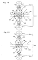
- Fig. 17 is a schematic front view showing an embodiment of the static eliminator of the invention.
- the static eliminator 5 can be preferably used for eliminating charges from a plastic film.
- Fig. 18A is an enlarged perspective view showing one static eliminating unit in an example of the static eliminator 5 shown in Fig. 17.
- Fig. 18B is a front view showing the positional relation of the members in an static eliminating unit in the static eliminator 5 shown in Fig. 17.
- the static eliminator 5 has a guide roll 5a on the left side and a guide roll 5b on the right side.
- a traveling film S is placed over the guide rolls 5a and 5b.
- the guide rolls 5a and 5b are revolved clockwise by respective motors (not shown in the drawing).
- the film S continuously travels at speed u (in mm/sec) in the arrow direction 5ab because of the revolution of the guide rolls 5a and 5b.
- n (n ⁇ 2) static eliminating units SU1, ..., SUn are installed with intervals kept between the respectively adjacent units in the traveling direction of the film S (in the arrow 5ab direction).
- the first static eliminating unit SU1 consists of a first electrode unit EUd-1 and a second electrode unit EUf-1.
- the first electrode unit EUd-1 faces the first surface 100 of the film S and is installed with a gap kept against the first surface 100.
- the second electrode unit EUf-1 faces the second surface 200 of the film S and is installed with a gap formed against the second surface 200.
- the first electrode unit EUd-1 and the second electrode unit EUf-1 face each other with the film S placed between them.
- the k-th static eliminating unit Suk like the first static eliminating unit Su1, consists of a first electrode unit EUd-k and a second electrode unit EUf-k.
- the first electrode unit EUd-k faces the first surface 100 of the film S and is installed with a gap kept against the first surface 100.
- the second electrode unit EUf-k faces the second surface 200 of the film S and is installed with a gap formed against the second surface 200.
- the first electrode unit EUd-k and the second electrode unit EUf-k face each other with the film S placed between them.
- the construction of the static eliminating unit SUk in the static eliminator 5 is explained below in reference to Figs. 18A and 18B. This explanation is made with the first static eliminating unit SU1 as a typical unit.
- the number n of the static eliminating unit is two or more, and the number and the intervals of the static eliminating units can be selected within the scope of the invention.
- the first electrode unit EUd-1 consists of a first ion-generating electrode 5d-1, a first shield electrode 5g-1 having an opening SOg-1 (not shown in the drawing) for the first ion-generating electrode 5d-1, and an insulating component 5i-1.
- the second electrode unit EUf-1 like the first electrode unit EUd-1, consists of a second ion-generating electrode 5f-1, a second shield electrode 5h-1 having an opening SOh-1 (not shown in the drawing) for the second ion-generating electrode 5f-1, and an insulating component 5j-1.
- the first and second ion-generating electrodes 5d-1 and 5f-1 are respectively consisted of array of needle electrodes installed with intervals kept between the respectively adjacent needle electrodes in the width direction.
- the opening SOg-1 of the first shield electrode 5g-1 is open toward the film S at near the pointed end of the first ion-generating electrode 5d-1 and has an opening width d 41 -1 in the traveling direction of the film S.
- the opening SOh-1 of the second shield electrode 5h-1 is open toward the film S at near the pointed end of the second ion-generating electrode 5f-1 and has an opening width d 42 -1 in the traveling direction of the film S. Therefore, the first and second shield electrodes 5g-1 and 5h-1 function to help the discharge at the respective ion-generating electrodes 5d-1 and 5f-1 when an adequate potential difference is given between the first and second ion-generating electrodes 5d-1 and 5f-1.
- the pointed end of the first ion-generating electrode 5d-1 and the pointed end of the second ion-generating electrode 5f-1 are disposed with a gap of d 1 -1 kept between them in the direction normal to the film S and with a gap of d 0 -1 kept between them in the traveling direction of the film S. Furthermore, the first shield electrode 5g-1 and the second shield electrode 5h-1 are installed with a gap of d 3 -1 kept between their regions nearest to the film S in the direction normal to the film S.
- the first ion-generating electrode 5d-1 and the second ion-generating electrodes 5f-1 are connected with a first AC power supply 5c and a second AC power supply 5e respectively different by 180 degrees in phase. As shown in Fig. 17, actually, the first ion-generating electrode 5d-1 and the second ion-generating electrode 5f-1 are connected with terminals opposite in polarity on both sides of a grounded point of one AC power supply. However, they can also be connected with respectively independent power supplies.
- the first and second shield electrodes 5g-1 and 5h-1 are respectively grounded.
- the first static eliminating unit SU1 explanation is made for the case where a positive voltage is applied to the first ion-generating electrode 5d-1 while a negative voltage is applied to the second ion-generating electrode 5f-1.
- the first ion-generating electrode 5d-1 generates positive ions 301
- the second ion-generating electrode 5f-1 generates negative ions 302.
- the electric field intensity between the first ion-generating electrode 5d-1 and the second ion-generating electrode 5f-1 is strong, the electric field causes the positive and negative ions 301 and 302 to be forcibly irradiated to the film S.
- the value of discharge current can be confirmed using an output current indicator (not shown in the drawing) installed in the first AC power supply 5c.
- the output current of the first AC power supply 5c can also be confirmed, if the high voltage line connecting the first ion-generating electrode 5d-1 with the first AC power supply 5c is held by the clamp of a clamp type ammeter and monitored.
- the discharge current value I 0 is brought as the current due to the discharge caused in the first ion-generating electrode 5d-1 by the electric field near the pointed end of the first ion-generating electrode 5d-1 owing to the potential difference between the first ion-generating electrode 5d-1 and the first shield electrode 5g-1.
- the discharge current value that has shown a constant value I 0 when the normal direction inter-electrode distance d 1 has been large increases. This phenomenon means that the difference of potential from that of the second ion-generating electrode 5f-1 intensifies the electric field near the pointed end of the first ion-generating electrode 5d-1.
- the increase of discharge current value is attributable to the potential difference (electric field) between the first ion-generating electrode 5d-1 and the second ion-generating electrode 5f-1. Therefore, this phenomenon occurs irrespective of the presence or absence of the film S between the first ion-generating electrode 5d-1 and the second ion-generating electrode 5f-1. Furthermore, for this reason, in the case where the film S exists, the first ion-generating electrode 5d-1 and the second ion-generating electrode 5f-1 cause positive and negative ions 301 and 302 to be forcibly irradiated to the film, irrespective of the charges of the film S.
- V 1 + V 2 is the effective value of potential difference between the first and second ion-generating electrodes
- a positive monopolar ion cloud is formed near the pointed end of the ion-generating electrode
- a negative monopolar ion cloud is formed near the pointed end of the ion-generating electrode
- both positive and negative ions exist between the ion-generating electrode and the insulating sheet, and the positive and negative ions are recombined with each other, to lower the ion concentrations.
- the Coulomb's force to the ions is also reversed in direction. So, the ion cloud irradiated to the insulating sheet cannot be a monopolar ion cloud.
- the wind that blows to go away from the ion-generating electrode is the wind known as "ion wind” or "corona wind.” If the applied voltage is a DC voltage, corona wind blows only to go away to the ion-generating electrode. On the other hand, if the applied voltage is a AC voltage, corona wind blows to go away from and to return toward the ion-generating electrode simultaneously. The position where two opposite wind in direction mixed, arrow type wind can be seen. This wind is called “arrow type corona wind”.
- the arrow type corona wind is explained as follows. Since the voltage applied to the ion-generating electrode is reversed in polarity before the ions generated by the ion-generating electrode reach the counter electrode (the film S in the invention), the ions are attracted back to the ion-generating electrode at velocity ⁇ E, and this is the wind. It is difficult to analytically obtain the condition under which this arrow type corona wind occurs.
- document DS11 explains that in the case where an AC voltage of 60 Hz and 10 kV is applied to a needle electrode in opposite to a grounded counter electrode even if the distance between the ion-generating electrode and the counter electrode (a plate electrode in document DS11) is as short as 40 mm, the arrow type corona wind can be observed. Furthermore, since the corona wind per se has close relation with the moving velocity ⁇ E of ions, it is considered that the following approximation is possible.
- the period of time taken for the ions generated from the ion-generating electrode to reach the film S can be obtained by dividing the distance d 1 /2 by the velocity of corona wind, and is proportional to d 1 2 /V. If the applied voltages are reversed in polarity twice or more within this time period, the ion concentration declines, and it can be considered that the ion cloud irradiated to the insulating sheet cannot be a monopolar ion cloud. Therefore, the condition for generating a monopolar ion cloud can be expressed by the following formula. 1/f ⁇ B x d 1 2 /V (where B is a constant)
- This condition means that the polarity of the applied voltages are reversed twice or more till the ions generated from the ion-generating electrode reach the film S, that is, the frequency of reversion is high. In this state, it is considered that positive and negative ions exist together between electrodes in the direction normal to the film S (in the direction of ion irradiation).
- the distance from the first ion-generating electrode 5d-1 to the film S and that from the second ion-generating electrode 5f-1 to the film S is assumed the same, but the ratio of both distance in a range from 1:2 to 2:1 occurs no matter. Since if the distance from the first ion-generating electrode 5d-1 to the film S is too large to form monopolar ion cloud, still the distance from the second ion-generating electrode 5f-1 to the film S is short to form monopolar ion cloud.
- negative ions generated from the second ion-generating electrode are forcibly irradiated to the second surface 200 of the film S as a negative ion cloud
- positive ions generated from the first ion-generating electrode are selectively irradiate to the first surface 100 of the film S. This automatically works to balance the deposition of positive and negative ion to the respective surfaces refer to the following.
- the positive ions 301 and the negative ions 302 are attracted near to the film S along the lines of electric force 500 formed by the first and second ion-generating electrodes 5d-1 and 5f-1, and are deposited on the film S.
- the positive ions 301 and the negative ions 302 are more selectively attracted by the negative charges 102 and the positive charges 201 due to the Coulomb force 700 if there exist the negative charges 102 and the positive charges 201 on the film S. Therefore, the negative charges 102 of the first surface of the film S and the positive charges 201 of the second surface are eliminated.
- the quantity of ions used for irradiation reaches several to 30 of microcoulombs per square meter in absolute value. Because of this, the charges of the respective surfaces of the film S can be greatly reduced though this could not have been achieved by the prior art. This means that the effect of eliminating the charge densities of both-side bipolar charges is high. This effect can be obtained only when the first ion-generating electrode 5d-1 and the second ion-generating electrode 5f-1 are disposed to face each other to simultaneously generate ions opposite to each other in polarity for forcibly irradiating both the surfaces with the ions.
- the interval of the pointed ends of the first and the second ion-generating electrodes 5d-1 and 5f-1 in the traveling direction of the film is smaller than the interval of the pointed end of the first ion-generating electrode and the respective point of second shield electrode in the traveling direction of the film, and smaller than the interval of the pointed end of the second ion-generating electrode and the respective point of the first shield electrode in the traveling direction of the film.
- the first and the second ion-generating electrodes face each other substantially symmetrically with virtual plane is preferred. It is most preferred that both sets of the electrodes perfectly face each other.
- the distance (electrode discrepancy) d 0 between the pointed end of the first ion-generating electrode 5d-1 and the pointed end of the second ion-generating electrode 5f-1 in the traveling direction at each position in the width direction of the film S satisfies the following formula
- the first ion-generating electrode 5d-1 and the second ion-generating electrode 5f-1 simultaneously generate ions opposite to each other in polarity for allowing the irradiation capable of achieving the object of the invention.
- This formula was obtained based on the examination by the inventors. This formula means the following.
- This formula indicates that if the ratio d 1 /d 3 of the distance (normal direction inter-electrode distance) d 1 between the pointed ends of the first and second ion-generating electrodes in the direction normal to the film and the shortest distance (normal direction inter-shield-electrode distance) d 3 between the first and second shield electrodes in the direction normal to the film is larger, the allowable range of the electrode discrepancy d 0 becomes wider. Furthermore, this formula indicates that if the radio d 1 /d 4 of the normal direction inter-electrode distance d 1 to the width d 4 of the openings of the first and second shield electrodes in the traveling direction of the film S is larger, the allowable range of the electrode discrepancy d 0 is wider.
- the value of the width d 4 of the openings is the average value of the width d 41 -1 of the opening of the first shield electrode 5g-1 and the width d 42 -1 of the opening of the second shield electrode 5h-1, i.e., the value of (d 41 -1 + d 42 -1)/2.
- the effect of the ion-generating electrodes facing each other is small, and the increase of discharge current due to the ion-generating electrodes facing each other little occurs. This means that since the electric field between the first ion-generating electrode 5d-1 and the second ion-generating electrode 5f-1 is weak, the forced irradiation of the positive and negative ions 301 to 302 to the film S little occurs.
- the quantities of deposited ions are smaller than at sites of the film S where positive charges 101 exist in the first surface 100 while negative charges 202 exist in the second surface 200.
- negative ions 302 are applied to the first surface 100, the quantity of deposited negative ions 302 is different from site to site of the film.
- the sites having the largest quantities deposited are sites where positive charges 101 exist in the first surface 100, and the sites having the next largest quantities deposited are non-charged sites.
- the sites having the smallest quantities deposited are sites where negative charges 102 exist.
- the new deposition of ions is the problem described to be likely to occur in the final pair of ion-generating electrodes of the static eliminator of document DS3 cited for explaining the prior art.
- the deposition of ions causes the unintentional charges especially to be noted carefully when the static eliminating units of the invention with large quantities of irradiated ions for both surfaces of the film are used.
- the countermeasure against the unintentional charges is described later.
- the apparent charges densities of the film are almost zero, and the macroscopic apparent charge irregularity occurring in the prior art such as the static eliminators (excluding the final pair of ion-generating electrodes) of documents DS2 and DS3 is hard to occur. This is explained below.
- the Coulomb force 700 due to the excessively deposited negative ions 302 inhibit the deposition of the negative ions 302 on the second surface 200 and promote the deposition of positive ions 301 on the first surface 100.
- This state can be achieved if the first ion-generating electrode 5d-1 and the second ion-generating electrode 5f-1 are disposed to face each other for simultaneously irradiating ions opposite to each other in polarity to both the surfaces of the film S.
- This state has been achieved for the first time by the invention.
- the balance in the charges of both the surfaces of the film S can be achieved in all the static eliminating units. Therefore, the film from which charges have been eliminated by the static eliminator composed of the static eliminating units disposed one after another are apparently liberated from charges very well. Therefore, the DC and/or AC static eliminating members used in the latter stage for eliminating the apparent macroscopic charge irregularity, needed in the static eliminators of documents DS2 and DS3 (the static eliminator 2 of Fig. 4 and the static eliminator 3 of Fig. 8) are not necessary.
- one static eliminating unit can surprisingly eliminate the positive (or negative) charges 101 (or 102) of the first surface 100 and the negative (or positive) charges 202 (or 201) of the second surface at the respective sites of the film.
- the apparent charge densities of the film S from which charges have been eliminated by the static eliminating unit are almost zero.
- one static eliminating unit only cannot eliminate the negative (or positive) charges 102 (or 101) of the first surface 100 or the positive (or negative) charges 201 (or 202) of the second surface 200. So, it is necessary to use plural static eliminating units.
- Fig. 22 is for explaining function of elimination of a portion of film S eliminated by the first static eliminating unit SU1 based on the second static eliminating unit SU2. It is considered that a case where a negative voltage is applied to the first ion-generating electrode 5d-2, while a positive voltage is applied to the second ion-generating electrode 5f-2. In this case, the first ion-generating electrode 5d-2 generates negative ions 302, and the second ion-generating electrode 5f-2 generates positive ions 301.
- the negative ions 302 and the positive ions 301 are respectively attracted near to the film S along the lines of electric force 500 formed by the first and second ion-generating electrodes 5d-2 and 5f-2.
- the positive and negative ions 301 and 302 eliminate the positive charges 101 of the first surface 100 of the film S and the negative charges 202 of the second surface 200 near the film S by means of the Coulomb force 700. If two static eliminating units are used like this, the first static eliminating unit can eliminate the negative charges 102 of the first surface 100 and the positive charges 201 of the second surface 200, while the second static eliminating unit can eliminate the positive charges 101 of the first surface 100 and the negative charges 202 of the second surface 200.
- Fig. 23 shows a state where the charges of the film S have been sufficiently eliminated. This state is very different from the charge-eliminated state achieved by the static eliminator of document DS2 referred to as a conventional technique shown in Fig. 7.
- Fig. 23 shows a state where positive charges 101 and 201 and negative charges 102 and 202 remaining, and the remaining charges are decided by the charge densities of the film S before static elimination and the quantities of irradiated ions per static eliminating unit.
- two static eliminating units only can eliminate charges to a substantially non-charged state. If this is repeated, when the quantities of irradiated ions are smaller than the charge densities before static elimination, the remaining positive charges 101 and 201 and negative charges 102 and 202 can be eliminated. If a pair of ion clouds opposite to each other in polarity are irradiated simultaneously to both the surfaces of the film S and further another pair of clouds opposite to each other in polarity but reversed in polarity compared with the ion clouds irradiated before are irradiated, the fine charges, especially both-side bipolar charges of the film S can be eliminated.
- low-frequency AC voltages can be applied to the ion-generating electrodes 5d-1 and 5f-1, for irradiating a pair of clouds of positive and negative ions 301 and 302 with the lapse of the time.
- high-frequency voltages can be applied like the static eliminator for a copier disclosed in document DS4 or document DS5, for applying mixed positive and negative ions to the respective surfaces, or DC voltages can be applied.
- the functions of the respective static eliminating units it was explained before that even if the ion-generating capability of the first ion-generating electrode is different from the ion-generating capability of the second ion-generating electrode, the quantities of deposited ions are automatically balanced.
- the capabilities of the static eliminating units the situation is different. That is, due to the difference between individual electrodes, contamination, wear with the lapse of time, deformation and the like, it is highly possible that, for example, the ion-generating capability of the first static eliminating unit SU1 is low while the ion-generating capability of the second static eliminating unit SU2 is high.
- the charge densities opposite to each other in polarity of the respective surfaces are weak if the actions of the static eliminating units are in a normal range, that is, unless there are neither wire breaking nor serious electrode deterioration or the like, and the charges are not so strong as to directly affect the grade of the film S.
- the film is wound as a roll, it is not preferred since the electric double layer with a large gap shown in document DS1 is formed.
- the electric double layer in a film roll refers to, as shown in Fig. 27, a state where as if there seems to be only positive charges 201 of the second surface 200 (inner surface) of the first layer S 1 and negative charges 102 of the first surface 100 (outer surface) of the outermost layer S f .
- the rear side equilibrium potentials of the film S can be measured after the static elimination, and based on the values, the voltages to be applied to the first and second ion-generating electrodes of each static eliminating unit can be controlled.
- this method is not preferred, since such a measure as installing another control system must be taken to complicate the apparatus.
- the irradiation irregularity causes the first surface 100 to be positively charged and the second surface 200 to be negatively charged at a specific site of the film S. Furthermore, at another site, the first surface 100 is negatively charged and the second surface 200 is positively charged.
- This state occurs similarly also in the case where the capabilities of static eliminating units are different. That is, even in the case where the ion-generating capability of the first static eliminating unit is low while the ion-generating capability of the second static eliminating unit is high, the influence of the irradiation irregularity by the second static eliminating unit relatively strongly appear over the entire film S, to charge the film S, and unlike the case where DC voltages are applied, it hardly occurs that the respective surfaces are charged predominantly monopolarly over the entire film S.
- the negative charges 102 of the first surface 100 (outer surface) of the j-th layer S j balance the positive charges 201 of the second surface 200 (inner surface) of the (j+1)-th layer S j+1 , causing there seems to be no charges to exist at the site, there occurs without fail a situation that the negative charges 102 of the first surface 100 (outer surface) of the m-th layer S m are identical in polarity with the negative charges 202 of the second surface 200 (inner surface) of the (m+1)-th layer S m+1 , where m is a positive integer different from j.
- the middle point between the pointed end of the first and second ion-generating electrodes of one static eliminating unit and the middle point of another static eliminating unit adjacent to said unit are positioned apart from each other with a distance d 2 in the traveling direction of the film S.
- the first ion-generating electrodes 5d-1 to 5d-n and the first shield electrodes 5g-1 to 5g-n are connected respectively to be the same in potential, while the second ion-generating electrodes 5f-1 to 5f-2 and the second shield electrodes 5h-1 to 5h-n are connected respectively to be the same in potential.
- the same AC power supply can be used as the power supply, or plural AC power supplies can also be used in synchronization. Synchronizing plural AC power supplies means that an AC voltage is applied while a predetermined phase difference is kept mutually among the ion-generating electrodes 5d-1 to 5d-n.
- the voltage applied to the first ion-generating electrodes of adjacent static eliminating units is an AC voltage of the same phase (phase difference zero).
- the ions opposite to each other in polarity generated from the first ion-generating electrodes of adjacent static eliminating units are recombined with each other to vanish. This state is not preferred, since the quantities of ions irradiated to the film surfaces are decreased.
- the purpose of installing static eliminating units one after another is, as describe before, such that the first static eliminating unit SU1 is used to eliminate the negative charges 102 of the first surface 100 (and the positive charges 201 of the second surface 200,) and that the second static eliminating unit SU2 is used to eliminate the positive charges 101 of the first surface 100 (and the negative charges 202 of the second surface 200.)
- the roles of the first static eliminating unit SU1 and the second static eliminating unit SU2 can also be reversed. Furthermore, in the case where three or more static eliminating units are used, it is only required that any static eliminating units have this relation, among all the static eliminating units.
- the optimization of the disposition should be especially taken into account together with the formation of monopolar ion clouds when the static eliminating unit of the invention having an especially high capability of forcibly irradiating ions to the film S is used.
- an ordinary static eliminator with a low ion irradiating capability it is difficult to form a monopolar ion cloud, and even if two or more static eliminators are installed one after another, the strong charges in the film due to ion irradiation irregularity are hard to occur.
- the static eliminators of documents DS2 and DS3 described for the explanation of the prior art macroscopic apparent charge irregularity is confirmed, but in these documents, no measure more than installing ion-generating electrodes one after another in the traveling direction of the film is described.
- This mode though ions are forcibly irradiated to the surfaces of a film, the ions sufficiently spread in the regions between the ion-generating electrodes and the film, and monopolar ion clouds spreading over the entire static eliminating gate consisting of plural static eliminating units is formed.
- This mode is called the weakly charging mode.
- the ions are more powerfully irradiated to the surfaces of a film.
- the ions are concentrated in the regions between the first and second ion-generating electrodes of respective static eliminating units, and a pair of ion clouds opposite to each other in polarity are formed for each static eliminating unit.
- This mode is called the strongly charging mode.
- V 0.085 x d 1 2 x f
- d 1 is the normal direction inter-electrode distance (in mm)
- V is the applied voltage (average of the first ion-generating electrode applied effective voltage V 1 and the second ion-generating electrode applied effective voltage V 2 ) (in V)
- f is the frequency of the applied voltage (in Hz).
- the mode satisfying the formula 0.0425 x d 1 2 x f ⁇ V ⁇ 0.085 x d 1 2 x f is the weakly charging mode in which the polarity of the applied voltage is reversed once or twice during the time for the ions generated from an ion-generating electrode to reach the film
- the mode satisfying the formula 0.085 x d 1 2 x f ⁇ V is the strongly charging mode in which the polarity of the applied voltage is reversed only once or less during the time for the ions generated from an ion-generating electrode to reach the film.
- the relation between the time for the ions generated from an ion-generating electrode to reach the film and the number of reversed time of the applied voltage is in the case the film S is at the middle position of the first and the second ion-generating electrode in normal direction.
- the position of the film discrepant from this in normal direction i.e., the distance from the first ion-generating electrode 5d-1 to the film S and that from the second ion-generating electrode 5f-1 to the film S are different, the number of reversed time of the applied voltage also change.
- these two modes are greatly depend on strength of electric field. Therefore, there is no problem in case where the ratio of the distance between the film and the first ion-generating electrode and the distance between the film and the second ion-generating electrode is shifted in the range from 1:2 to 2:1.
- the ion cloud spread a tends to be larger, and if the ratio d 1 /d 4 of the normal direction inter-electrode distance d 1 to the shield electrode opening width d 4 is larger, the ion cloud spread a tends to be larger. It is preferred that the adjacent electrode is near the ion cloud spread a.
- the inventors found that if the static eliminating unit interval d 2 is less than about 80% of the ion cloud spread a, that is, if the following relation d 2 ⁇ 12 x d 1 2 /(d 3 x d 4 ) (in mm) is satisfied, the ions from the adjacent static eliminating units superimpose each other when they reach the film surfaces. If a voltage of the same phase is applied to the first ion-generating electrodes of all the static eliminating units installed one after another, it can be considered that the ions are irradiated to the film while having a spread substantially as one monopolar ion cloud on the film surfaces.
- the first static eliminating unit eliminates the negative charges 102 of the first surface 100
- the second static eliminating unit eliminates the positive charges 101 of the first surface 100, or vice versa. That is, it is allowed that all the ions irradiated to the first surface 100 are identical in polarity when specific sites of the film S pass directly under the respective static eliminating units (in the state of synchronous superimposition) .
- the whole ion cloud spread in the weakly charging mode is the length of the static eliminating gate (D 2 ) plus a.
- D 2 the distance the film travels at speed u (in mm/sec) while the applied voltage changes per cycle is u/f. Therefore, it is only required to satisfy the formula D 2 + a > u/f.
- the irradiation irregularity can be considered as described below. Since the respective sites of the film S are irradiated with positive and negative ions 301 and 302 continuously temporally and spatially, the filmS, i.e., the first surface 100 of the film S does not have any site where monopolar ions only are applied. Therefore, the quantity of final charges of the respective surfaces of the film S is smaller than the sum (n times) of irradiation irregularities of respective static eliminating units.
- the weakly charging mode refers to a region where the arrow type ion wind occurs
- the irradiation irregularity per static eliminating unit is small.
- the inventors examined the charge densities of the irradiation irregularity using a non-charged film, and the irregularity was found to be like sinusoidal waves having an amplitude of about 1 to about 15 ⁇ C/m 2 in the respective surfaces. Therefore, for example, in the static eliminator consisting of 10 static eliminating units, the final charge densities (the sums of irradiation irregularities) of the film S is less than 150 ⁇ C/m 2 in absolute value.
- the original charge density can be decreased to such a value obtained by subtracting 150 ⁇ C/m 2 from the original charge density in absolute value. If the original charge density is in a range from about 150 to about 300 ⁇ C/m 2 in absolute value, there is little difference between the charge density achieved after static elimination at an originally charged site of the film S and that at an originally non-charged site of the film S.
- the charge density has been kept at 150 ⁇ C/m 2 or less in absolute value
- the rear side equilibrium potential can be kept at 340 V or less in absolute value.
- the rear side equilibrium potential can be so high in absolute value as to cause coating irregularity even if the charge density is kept at 150 ⁇ C/m 2 or less in absolute value.
- the film has a thickness of 60 ⁇ m or more, it is preferred in view of inhibiting the coating irregularity, not only to keep the charge density in a range from -150 ⁇ C/m 2 to 150 ⁇ C/m 2 , but also to keep the rear side equilibrium potential in a range from -340 V to 340 V, considering the influence of the film thickness on the rear side equilibrium potential of the film.
- the amplitude of charge density caused by the irradiation irregularity per static eliminating unit is, as described before, about 15 ⁇ C/m 2 at the highest in the weakly charging mode.
- the net number of static eliminating units that are allowed to be used in the synchronous superimposition state can be obtained as an integer in a range from 0 to 0.0006/d f , the value obtained by dividing the allowable value of charge density (0.009/d f ⁇ C/m 2 ) by the highest value of the amplitude of charge density of irradiation irregularity 15 ⁇ C/m 2 .
- the total number of the static eliminating units is not allowed, it must be canceled out. So, in order to keep the final rear side equilibrium potential respective surfaces of the film in a range from -340 to + 340 V, it is only required that the voltages applied to the first ion-generating electrodes are identical in polarity, in the number of static eliminating units in a range from the value of (n - 0.0006/d f ) /2 to the value of (n + 0.0006/d f )/2, when respective sites of the film pass directly under the respective static eliminating units.
- the number of static eliminating units is a integer. So, the above mentioned number of static eliminating units where voltages of same polarity are applied to the first ion-generating electrodes of them can be chosen from integer 0 to n.
- the value of (n - 0.0006/d f ) /2 is a minus number.
- a film with a thickness of less than 60 ⁇ m is used in a static eliminator consisting of 10 static eliminating units.
- the voltages applied to the first ion-generating electrodes of all the static eliminating units can be identical in polarity. That is, it means that the synchronous superimposition state is allowed.
- the number of the static eliminating units where voltages of the same polarity are applied to the first ion-generating electrode of them can be any number from 0 to n.
- the weakly charging mode since the ions spread over the static eliminating gate as a whole, the synchronous superimposition state is allowed, as described before.
- the allowable charge density allowed in this case is 0.0053/d f ⁇ C/m 2 in absolute value in the case where the film is a polyethylene terephthalate film and where the value of its dielectric constant ⁇ r is 3.
- the total number of static eliminating units is n, when respective sites of the film pass directly under the respective static eliminating units, it is only required that the voltages applied to the first ion-generating electrodes are identical in polarity, in the number of static eliminating units in a range from the value of (n - 0.00035/d f )/2 to the value of (n + 0.00035/d f )/2.
- the above mentioned number of static eliminating units where voltages of same polarity are applied to the first ion-generating electrodes of them can be chosen from integer 0 to n.
- the weakly charging mode cannot be used.
- the absolute quantity of ions is small in the weakly charging mode, very many static eliminating units, that is, tens of to 100 static eliminating units are necessary for decreasing the quantities of charges of the respective surfaces to the desired value.
- the strongly charging mode the quantities of ions generated by the respective ion-generating electrodes are large, and total irradiation irregularity is large. So, countermeasures against them are necessary.
- the influence of the arrow type corona discharge virtually vanishes, and the ions are concentrated directly under the ion-generating electrode that have generated the ions. Therefore, the ion clouds cannot be identified as a monopolar ion cloud spreading over the static eliminating gate as a whole, but must be identified as plural pairs of small ion clouds formed to spread in relation with the respective static eliminating units.
- the film S is irradiated with spatially discrete plural pairs of positive and negative ion clouds.
- the final charges of the first surface 100 of the film S are in the form of the sums of the irradiation irregularities by the respective static eliminating units at originally non-charged sites of the film S. If the numbers of the ion clouds irradiated to the film S are almost the same irrespective of polarity, the static elimination effect is highest. Furthermore, since the irradiation irregularities by the respective static elimination units are cancelled out, finally the charge densities of the respective surfaces of the film S caused by the irradiation irregularities are almost zero.
- the polarity of the ion clouds corresponding to 1/4 or more of all the ion clouds is opposite to that of the other ion clouds, one half or more of the applied ions are effectively consumed for static elimination. Furthermore, the action for mutually weakening the irradiation irregularities from the respective static eliminating units is stronger than the action for mutually strengthening the irradiation irregularities. Therefore, among the ion clouds applied to all the sites in the traveling direction of the film S, it is preferred that the polarity of the ion clouds corresponding to 1/4 or more of the ion clouds is opposite to that of the other ion clouds.
- the voltages applied to the ion-generating electrodes have a waveform smoothly changing in polarity such as sinusoidal waves, triangular waves or trapezoidal waves, if the polarity of the ion clouds corresponding to 1/4 or more of all the ion clouds is opposite to the polarity of the other ion clouds over the sites corresponding to 2/3 or more of all the sites in the traveling direction of the film S, there arises no practical problem.
- the irradiation irregularity in these sites is caused by the ions generated immediately before and after the moment when the voltages applied to ion-generating electrodes are reversed in polarity.
- the voltages applied to ion-generating electrodes have a waveform changing smoothly in polarity such as sinusoidal waves or triangular waves, the quantities of ions generated immediately before and after the moment when the applied voltages are reversed in polarity are small. Therefore, since the irradiation irregularities at the sites are small, no large irregularities occur in the final charges of the respective surfaces of the film S.
- the synchronous superimposition intensity X of the ions applied to the respective surfaces of the film S can be obtained from the following equation.
- X
- where ku ⁇ fd 20 , and k 1, 2, 3, ...
- the distribution of the charge densities of the first surface 100 of the film S by the irradiation irregularity of the first static eliminating unit is sin(2 ⁇ fx/u)
- the distribution of the charge densities of the first surface 100 of the film S by the irradiation irregularity of the second static eliminating unit can be expressed in the form of sin(2 ⁇ f(x - d 20 )/u) since the static eliminating unit interval is d 20 . That is, for the respective static eliminating units adjacent to each other with static eliminating unit intervals of d 20 , the distribution of the charge densities caused by irradiation irregularities shifting by phase (2 ⁇ fd 20 /u) respectively occur.
- the sum of these distributions of the charge densities is the final charge distribution of the first surface 100 of the film S.
- the value of said X corresponds to the amplitude of the sum.
- ions are applied to the film S in such a manner that the polarity of the ion clouds corresponding to 1/4 or more of all the ion clouds is opposite to that of the other ion clouds over the sites corresponding to 2/3 or more of all the sites in the traveling direction of the film S.
- n 10 (10 static eliminating units)
- the values of X for u/(d 20 x f) are obtained and shown in the graph of Fig. 26.
- the value of the speed to the static eliminating unit interval standardized by the frequency ⁇ u/(d 20 x f) ⁇ is chosen as the abscissa, and the value of synchronous superimposition intensity X, as the ordinate.
- the charge densities of respective surface of the film S by the irradiation irregularities from all the static eliminating units are suppressed to less than one half compared with the case of synchronous superimposition. If irradiation irregularities are superimposed with various phase differences, that is, phase differences corresponding to distances d 20 , 2d 20 , 3d 20 , ... under plural static eliminating units, the irradiation irregularities are more cancelled out in reverse phases, rather than they are emphasized in the same phases. This means that finally the charge irregularity of the film S is low.
- the strongly charging mode is useful in the case where the formula V > 0.085 x d 1 2 x f holds, judging from the formula applicable in the case where the arrow type corona wind occurs.
- the irradiation irregularities per static eliminating unit are larger than in the weakly charging mode.
- the inventors examined the distributions of charge densities caused by the irradiation irregularities per static eliminating unit using a non-charged film, and the distributions of the respective surfaces were like sinusoidal waves with an amplitude of about 10 to about 30 ⁇ C/m 2 in absolute value.
- the absolute values of the final charge densities (sums of the charge densities by the irradiation irregularities (highest amplitude values) of the respective surfaces of the film S can be kept smaller than 150 ⁇ C/m 2 .
- the original charge density can be decreased to such a value obtained by subtracting from 150 ⁇ C/m 2 to 300 ⁇ C/m 2 from the original charge density in absolute value. If the original charge density is in a range from about 300 to about 500 ⁇ C/m 2 in absolute value, there is little difference between the charge density achieved after static elimination at an originally charged site of the film S and that at an originally non-charged site of the film S.
- the absolute values of the charge densities in the respective surfaces of the final film S can be kept at less than about 30 ⁇ Cm 2 , the amplitude of charge densities due to the irradiation irregularities per static eliminating unit and a substantially non-charged film S can be obtained.
- the strongly charging mode in the case where it is desired to control the quantities of charges of a film to be coated later, in reference to potentials, the following consideration can be employed as in the weakly charging mode.
- the charge density in absolute value for keeping the rear side equilibrium potential of the film at 340 V or less in absolute value is 0.009/d f ⁇ C/m 2 or less as described before.
- the amplitude of charge density caused by the irradiation irregularity per static eliminating unit is about 30 ⁇ C/m 2 at the highest as described before.
- the net number of static eliminating units that are allowed to be used in the synchronous superimposition state is obtained as an integer in a range from 0 to 0.0003/d f , the value obtained by dividing the value of allowable charge density (0.009/d f ⁇ C/m 2 ) by 30 ⁇ C/m 2 that is the highest value of the amplitude of charge density of irradiation irregularities per a static eliminating unit.
- the number of static eliminating units is a integer. So, the above mentioned number of static eliminating units where voltages of same polarity are applied to the first ion-generating electrodes of them can be chosen from integer 0 to n
- the value of (n - 0.0003/d f ) /2 becomes minus. This means that in the case where the film S has a thickness of less than 30 ⁇ m, even if the ten static eliminating units are in the synchronous superimposition state in the strongly charging mode, the coating irregularity of the coating material in the post-processing does not occur since the final rear side equilibrium potential of respective surfaces of the film S due to irradiation irregularities are in a range from -340 V to 340 V.
- the voltages applied to the first ion-generating electrodes of at least one static eliminating unit should be opposite in polarity. Even if the synchronous superimposition state is in an allowable range for the coating irregularity caused by the final charges of the film S due to the superimposition of irradiation irregularities, synchronous superimposition is not a preferred state from the viewpoint to decrease the charge densities of the respective surfaces of the film S before static elimination, i.e., in view of static elimination. To achieve the purpose of static elimination, it is preferred that the net number of static eliminating units that are allowed be used in the synchronous superimposition state is up to n-1 at the largest.
- the voltages applied to the first ion-generating electrodes are identical in polarity, in the number of static eliminating units in a range from (n - 0.0003/d f ) /2 to (n + 0.0003/d f )/2, when respective sites of the film S pass directly under the respective static eliminating units, and the above mentioned number of static eliminating units is integer number from 1 to n - 1.
- the two static elimination modes of the strongly charging mode and the weakly charging mode can be adequately selectively used in the case where portions different in speed exist in one product in the secondary processing of the film S, for example, in a slitting process.
- the static eliminating unit intervals d 20 and the applied voltage frequency f are set to achieve 0 ⁇ X ⁇ 0.5, and in this range, the strongly charging mode is used.
- low voltages can be applied to employ the weakly charging mode for static elimination, for avoiding the strong irradiation irregularities in the strongly charging mode. Setting can be made to achieve 0 ⁇ X ⁇ 1/n instead of 0 ⁇ X ⁇ 0.5
- the transfer to the spark discharge decides the upper limit of the applied voltage V.
- the spark voltage of negative corona i.e., the voltage V b (in V) in absolute value at which the negative corona discharge with a negative DC voltage applied transfers to the spark discharge is proportional to the inter-electrode distance d (in mm) , being about 1500d.
- the voltage at which the spark voltage of positive corona i.e., the voltage at which the positive corona discharge with a positive DC voltage applied transfers to the spark discharge is about 1/2 of V b .
- the positive-side peak voltage must be kept smaller than V b /2. That is, if the same effective voltage V applied to the first and second ion-generating electrodes respectively it is only required that the one-side peak voltage V p satisfies the formula V p ⁇ 750 x d 1 .
- the formula expressed by the effective voltage V in the case where an AC voltage is applied is V ⁇ 530 x d 1 .
- the upper limit of the applied voltage V actually depends on such as the structure of the electrode unit, in the case the distance between the ion-generating electrode and the shield electrode is short, or the like.
- the possible value of the normal direction inter-electrode distance d 1 is in a range from about 20 to about 100 mm, more preferably, about 25 to about 40 mm, though also depending on the frequency.
- the first and second shield electrodes 5g-1 to 5g-n and 5h-1 to 5h-n of respective static eliminating units are grounded.
- a potential difference can also be given between the first and second shield electrodes 5g-k and 5h-k of k-th static eliminating unit SUk, to generate an electric field between them.
- the applied potential of the first and second shield electrodes of all the static eliminating units are preferably respectively the same.
- the method for generating a weak electric field between the first and second shield electrodes 5g-k and 5h-k can be preferably used, for example, for actively feebly charging the respective surfaces of a film S greatly different in charge characteristic between the first surface 100 and the second surface 200, for canceling the unbalance in the quantity of frictional charges when charges are eliminated from the film S.
- a film S greatly different in charge characteristic between the first surface 100 and the second surface 200 there is a film obtained by coating the second surface of a base film with a coating material.
- the first surface 100 is likely to be negatively charged due to the properties of the base film
- the second surface 200 is likely to be positively charged due to the influence of the coating material.
- first and second shield electrodes 5g-1 to 5g-n and 5h-1 to 5h-n are preferred to electrically connect with each other for keeping the same potential.
- first and second shield electrodes 5g-1 to 5g-n and 5h-1 to 5h-n are simplest and preferred to ground both the first and second shield electrodes 5g-1 to 5g-n and 5h-1 to 5h-n.
- Figs. 29 and 30 show examples of the discharge electrodes used as the first and second electrode units Eud-k and Euf-k, for irradiating positive and negative ions 301 and 302 substantially simultaneously to both the surfaces of the film S by an electric field between the electrodes facing each other.
- a discharge electrode 7 consists of an ion-generating electrode 7a, a shield electrode 7b, a high voltage core wire 7c connected with a high voltage power supply (not shown in the drawing) and an insulating component 7d for separating the ion-generating electrode 7a from the shield electrode 7b.
- a discharge electrode 8 consists of an ion-generating electrode 8a, a shield electrode 8b, a high voltage core wire 8c connected with a high voltage power supply (not shown in the drawing), and an insulating component 8d for separating the ion-generating electrode 8a from the shield electrode 8b.
- a constitution as shown in Fig. 29 in which the ion-generating electrode 7a is directly coupled with the high voltage core wire 7c can be used, or a constitution as shown in Fig. 30 in which the ion-generating electrode 8a and the high voltage core wire 8c are capacitively coupled through the insulating component 8d can be used.
- a constitution in which the ion-generating electrode and the high voltage core wire are resistance-coupled through a protective resistance can also be used.
- the shield electrode 7b or 8b is positioned behind the ion-generating electrode 7a or 8a, and that the ion-generating electrode 7a or 8a is insulated from the shield electrode 7b or 8b by the insulating component 7d or 8d.
- the shield electrode can also be split into a component forming an opening near the pointed end of the ion-generating electrode and a component for shielding the rear side of the ion-generating electrode. As shown in Fig. 29 or 30, an integral shield component can also be employed.
- a static eliminator as shown in Fig. 17 in which the first and second ion-generating electrodes 5d and 5f are disposed to face each other, if the applied voltages are raised, spark discharge may occur between the first ion-generating electrode 5d and the second ion-generating electrode 5f. If shield electrodes are positioned also at the rear sides, stable corona discharge occurs between the shield electrodes and the ion-generating electrodes. If insulating components are used for insulating ion-generating electrodes from the rear sides of shield electrodes, the spark discharge between ion-generating electrodes and shield electrodes can be inhibited. These methods are described in JP 53-6180 B (hereinafter called document DS13) .
- the rear side in this case means the side of the pointed ends of an ion-generating electrode, in opposite to the ion-generating electrode disposed to face the former electrode.
- a shield electrode is disposed near the ion-generating electrode, it can share the base plate or the like supporting the electrodes as a whole. It is preferred that the distance between an ion-generating electrode and a shield electrode is shorter than the normal direction inter-electrode distance d 1 . It is preferred that the distance between an ion-generating electrode and a shield electrode is in a range from about 5 to about 20 mm. A more preferred range is from about 10 to about 15 mm.
- the normal direction inter-shield-electrode distance d 3 can also be smaller than the normal direction inter-electrode distance d 1 .
- the tips of a shield electrode is positioned in front of the pointed ends of an ion-generating electrode in the direction to face the ion-generating electrode disposed to face the former electrode.
- the shield electrode absorbs many of the generated ions, to decrease the quantity of ions. It is preferred that the position of a shield electrode satisfies formula 0.9 ⁇ d 1 /d 3 ⁇ 1.15.
- the ion-generating electrode is an array of needle electrodes as shown in Figs. 29, 30 and 31.
- An electrode with low rigidity such as a wire electrode is not preferred in the case where the charges of a wide film are eliminated, since a loose wire or slight deviation of the wire in parallelism makes the normal direction inter-electrode distance d 1 irregular in the width direction of the film, the uniformity of discharge in the width direction being liable to be lost.
- the intervals of the needle electrodes (intervals in the width direction) d 5 are in a range from about 1/2 time to about 2 times the static eliminating unit intervals d 2 , and in a range from about 10 to about 40 mm. It is preferred that the opening of a shield electrode is continuous in the width direction as shown in Fig. 31.
- the opening of a shield electrode is continuous in the width direction, the ions generated from the individual needle electrodes of each ion-generating electrode spread in the width direction.
- the difference in the quantity of irradiated ions between the positions directly under the needle electrodes and the positions under the regions between the needle electrodes is small.
- the sites of the film passing directly under the needle electrodes and the sites of the film under the regions between the needle electrodes are little different in the magnitude of charge densities caused by irradiation irregularity.
- the difference in the magnitude of charge densities caused by irradiation irregularity is only about one half at the largest.
- the value of the amplitude, 30 ⁇ C/m 2 as the charge density of the film due to irradiation irregularity described before is the largest value in the width direction and corresponds to the sites of the film passing directly under the needle electrodes.
- the intervals of the tips of the needle electrodes of the first and second ion-generating electrodes in the width direction can be larger than the electrode discrepancy d 0 and can be about the distance d 1 between the pointed ends of the ion-generating electrodes in the direction normal to the sheet without any problem.
- the opening of a shield electrode is provided as openings discrete in the width direction of the film, for example, in the case where a pipe-shaped electrode with round holes formed only near the needle electrodes is used as the shield electrode, it is preferred that the intervals of the corresponding tips of the needle electrodes of the first and second ion-generating electrodes in the width direction of the film are virtually equal to the electrode discrepancy d 0 .
- the shield electrode does not have any opening in some positions in the width direction.
- the values of the shield electrode opening width d 4 and the like in the invention cannot be specified. In this case, it is only required that the formulae of the invention hold at the respective positions in the width direction where the openings of the shield electrode exist.
- n 1 is not preferred since there is some sites in which only either positive or negative ions can be irradiated to the respective surfaces of the traveling film at the respective sites. In order that both the positive and negative ions are irradiated to the respective surfaces of the traveling film at the respective sites, it is necessary that formula n ⁇ 2 should be satisfied.
- the charge densities of the respective surfaces of the film can be sufficiently lowered, but the number n of all the static eliminating units is selected based on the quantities of local charges of the respective surface of the film and the quantities of allowable charges depending on the post-processing. If the quantities of charges to be decreased in absolute value of the charge densities are in a range from about 30 to about 200 ⁇ C/m 2 , the adequate number n of static eliminating units in the weakly charging mode is in a range from 10 to 20, and the adequate number n of static eliminating units in the strongly charging mode is in a range from 5 to 10.
- the quantities of charges to be decreased in absolute value of the charge densities are in a range from about 300 to about 500 ⁇ C/m 2
- the adequate number n of static eliminating units in the weakly charging mode is in a range from 20 to 40
- the adequate number n of static eliminating units in the strongly charging mode is in a range from 10 to 20.
- the static eliminating gate length D 2 There is no theoretical upper limit for the static eliminating gate length D 2 , and the static eliminating gate length D 2 can be decided at an adequate value based on the number of electrode units used and practical dimensions. It can be said that the upper limit in an actual film producing apparatus or processing apparatus is about 1000 mm. In the case where the static eliminating gate length D 2 must be further longer, a sufficient effect can be obtained, even if, for example, ten static eliminating units are disposed in two groups, each consisting of five units.
- the film from which charges have been eliminated according to the invention does not cause discharge even if it approaches or gets in contact with a grounded nearby structure such as a carrier roll, even if it is not treated by means of DC and/or AC static eliminating members in the latter stage.
- Respective two adjacent static eliminating units for example, the first static eliminating unit SU1 and the second static eliminating unit SU2 can share a part of the shield electrode 5g-1 and a part of the shield electrode 5g-2.
- the AC voltage applied to the first ion-generating electrodes is different by 180 degrees in phase from that applied to the second-ion-generating electrodes.
- the reason is that the electric field can most strongly and efficiently attract the positive and negative ions 301 and 302. If there is a phase difference of about 180 degrees, even if some phase shift is caused due to the capacities of the power supply and the load, especially due to the electric shock protecting capacity directly inserted between the high voltage line and the needle electrodes, the static eliminator can be used without any problem.
- the frequency f is in a range from about 20 to about 200 Hz.
- the value of frequency f can be arbitrarily selected, if the conditional formula (0.0425 d 1 2 f ⁇ V) for causing forced irradiation of positive and negative ions 301 and 302 to the film S between the first and second ion-generating electrodes, the value of X expressing the synchronous superimposition intensity and the formula expressing the relation between the static eliminating gate length and the cycles of the applied voltage are satisfied. Considering them, it can be said that said range, i.e., a range from 20 to 200 Hz is adequate.
- the reasons why 50 Hz or 60 Hz as a power frequency of Japan is used are that a sufficient static elimination effect can be obtained, and that the static eliminator can be simplified and reduced in cost.
- the electrodes unit discharge electrodes of ordinary static eliminators to which a power frequency can be applied can be used, and the discharge electrodes described before and shown in Fig. 29 and 30 can be preferably used.
- the first surface 100 and the second surface 200 of the film S are respectively simultaneously irradiated with monopolar ion clouds substantially opposite to each other in polarity at the respective sites, and subsequently the first surface 100 and the second surface 200 are irradiated with monopolar ion clouds reversed in polarity to those used for the previous irradiation. So, the positive and negative charges 101, 102, 201 and 202 existing together in both the surfaces of the film S can be efficiently eliminated, and a substantially non-charged film can be produced.
- the charge densities of the respective surfaces of the film change cyclically virtually like sinusoidal waves in the traveling direction of the film, and the amplitude is in a range from 2 to 150 ⁇ C/m 2 .
- the apparent charge densities of the respective surfaces of the film are in a range from -2 to +2 ⁇ C/m 2 .
- a film in which the charges change smoothly cyclically virtually like sinusoidal waves has a small electric field in the in-plane direction of the film. So, problems due to static electricity are hard to occur.
- the film from which charges have been eliminated according to the invention is suitable for forming a functional layer at least on one side, since the charge densities of the respective surfaces of the film are in a range from -150 to +150 ⁇ C/m 2 .
- the film from which charges have been eliminated according to the invention is most suitable for producing a metallized film on which a deposited metal layer is formed as a functional layer.
- the film is not preferred as a film to be used for producing a metallized film, since the metallized film as a whole have positive or negative charges.
- the metallized film as a whole have positive or negative charges.
- the charges are alternately positive and negative, even if the metallized film obtained from a film liberated from charges according to the invention has a large area, the positive and negative charges existing together to cancel each other, to keep the total quantity of charges small.
- the apparent charge densities are in a range from -2 to +2 ⁇ C/m 2 , showing a good balance and an apparently non-charged state. Since the film from which charges have been eliminated according to the invention is apparently non-charged, it is hard to cause such problems as the occurrence of new static marks. Especially when the charge densities of the respective surfaces of the film are in a range from -30 to +30 ⁇ C/m 2 , such problems as discharge are not caused even if the film is post-processed under the influence of charges perfectly on one side through metallization, etc.
- the film in this charged state can be said to be a substantially non-charged film
- the value of charges densities can be controlled by a method of lowering the applied voltages near to the lower limit of the weakly charging mode, or by a method of controlling the static eliminating unit intervals, the traveling speed of the film or the frequency of the applied voltages to lessen the value of X expressing the synchronous superimposition intensity.
- the apparent charge densities at given sites of the film are in a range from -2 to +2 ⁇ C/m 2 .
- a 10 cm x 10 cm piece is cut from the film, and the distributions of charge densities at the same positions in the in-plane direction of the first surface 100 and the second surface 200 are measured at 20 places or more in the direction perpendicular to the traveling direction of the film and continuously in the traveling direction of the film. The results of measurement should be kept in said range.
- a toner powder is sprinkled over the film, holding sufficiently far from grounded conductor, such as one hundred times of the film thickness or more.
- the deposition state is evaluated whether the toner deposited locally or not.
- toner powders are deposited on local site where apparent charge density is high. In most cases, if there are such local charges that the apparent charge density of 1 ⁇ C/m 2 or more in absolute value, the toner will be deposited on the film. Consequently, if the film no toner deposited locally, local sites apparent charge 1 ⁇ C/m 2 or more in absolute value are considered nowhere in the film.
- the toner won't be deposited on the film.
- the apparent charge density (average value) is in a range from -1 to +1 ⁇ C/m 2 . If the distance between the film and the grounded conductor became larger, the higher the value of aerial potential of the film. Consequently, For measurement of the aerial potential, it is enough that the shortest distance between film and grounded conductor can be used. For example, it is sufficiently, if the shortest distance between film and grounded conductor is 10 mm or more, and if the value of aerial potential is in a range form -1000 to +1000 V, to consider the average value of the apparent charge density is in a range form -1 to +1 ⁇ C/m 2
- static eliminating units have the same forms and arrangement and can be operated with the same voltages applied.
- Both static eliminating units operated in the strongly charging mode and static eliminating units operated in the weakly charging mode can be used together as a combination of static eliminating units different in static elimination action.
- a static eliminator other than the static eliminator of the invention can also be used together.
- the film passes at the centers between the pointed ends of the first and second ion-generating electrodes, so that the difference between the quantities of the ions irradiated from the first and second ion-generating electrodes can be kept small, and in order to avoid as far as possible that the film is flawed due to the contact with the pointed ends and the like of the ion-generating electrodes.
- the film is made to travel under such a condition that the film does not sag, and it is preferred that the static eliminating units are constituted such that the angle ⁇ formed between the traveling direction 51 of the film S and the vertical direction 5k may be 45° or less, most preferably 0° as shown in Fig. 32.
- the angle ⁇ is defined in absolute value, and even if the traveling direction of the film S is reverse, the angle should be the same.
- a toner used in copiers was sprinkled over the sites of the film from which charges had been eliminated.
- the deposition state was evaluated in reference to the following three stages.
- the surface of the film, the charge distribution of which was to be evaluated (hereinafter called the surface to be evaluated) was kept in contact with a stainless steel (SUS) plate, and the rear surface was wiped with ethanol and dried, to neutralize the charges of the rear surface only.
- the film was then separated from the SUS plate, and a toner was sprinkled over the surface to be evaluated.
- the deposited state was evaluated in reference to the following three stages.
- a film was coated with a coating material, Isopar (Isopar H) (trade name of Exxon Chemical), and coating irregularity, i.e., whether there were sites locally repelling the coating material was examined.
- the film was placed on a metallic plate, and a metering bar with a wire diameter of 0.25 mm was used to hand-coat the insulating sheet with the coating material at a speed of about 0.3 m/sec.
- the film as placed on the metallic plate and the film separated from the metallic sheet were visually observed, and the coating irregularity was evaluated in reference to the following two stages.
- a film was coated with a silicone-based releasing agent (solvent toluene: KS847H produced by Shin-Etsu Chemical Co., Ltd. 10 parts by weight, PL-50T 0.1 part by weight, toluene 100 parts by weight), and coating irregularity, i.e., whether there were sites locally repelling the coating material was evaluated.
- the film was placed on a metallic plate, and a metering bar with a wire diameter of 0.25 mm was used to hand-coat the film with the coating material at a speed of about 0.3 m/sec.
- the film as placed on the metallic plate and the film separated from the metallic sheet were visually observed, and the coating irregularity was evaluated in reference to the following two stages.
- the surface reverse to the surface to be evaluated of a film was kept in contact with a metallic roll that was a hard chromium-plated roll with a diameter of 10 cm, and the potentials were measured.
- a metallic roll that was a hard chromium-plated roll with a diameter of 10 cm
- the electrostatic voltmeter was placed at a position of 2 mm above the film. The field of vision at this position was in a range with a diameter of about 6 mm according to the catalogue of Monroe electronics, inc.
- the metallic roll was revolved at a low speed of about 1 m/min using a linear motor, while the rear side equilibrium potentials V f (in V) of the surface to be evaluated were measured using the electrostatic voltmeter.
- the highest value of the absolute values of the rear side equilibrium potentials in plane was obtained. That is, the electrostatic voltmeter was relatively moved to scan about 20 mm in the width direction of the film, and the position in the width direction at which the highest value of the absolute values was obtained decided. Then, the position in the width direction was fixed, and the electrostatic voltmeter was moved relatively for scanning in the traveling direction of the film in which charges had been eliminated from the film, i.e., in the length direction of the film, to measure the potentials. It is ideal to measure the rear side equilibrium potentials in the plane of the film at all the two-dimensional points, but according to the above-mentioned method, the distribution of potentials in the plane of the film was approximated.
- the film had a width of more than 1 m
- about 20 mm wide pieces were cut out at almost the central portion and edge portions in the width direction of the film.
- the electrostatic voltmeter was moved relatively for scanning to find a place where the highest value was obtained, and subsequently, it was moved relatively for scanning in the traveling direction of the film in which charges had been eliminated from the film, to measure potentials.
- the rear side equilibrium potentials can be measured among the traveling direction in the width direction of that portion, in both the film which did not undergo static elimination and which underwent static elimination. In this way, the highest value of the absolute values in the plane of the film was obtained.
- the measured result was evaluated in reference to the following three stages.
- the relative dielectric constant ⁇ r of polyethylene terephthalate was 3. The largest value of the absolute values of calculated charge densities was evaluated in reference to the following three stages.
- a 105 mm x 150 mm piece was cut out of a film, and a 12 ⁇ m thick aluminum foil with the same size was stuck to the surface reverse to the surface to be evaluated of the film.
- the laminated film was placed on a larger straight SUS plate, to be as flat as possible with the surface to be evaluated kept in contact with the SUS plate.
- the film was pulled horizontally, and the largest load (in g) when the film started to move was measured using a spring balance. The obtained value was evaluated in reference to the following three stages.
- a biaxially oriented 200 mm wide 6.3 ⁇ m thick polyethylene terephthalate film (Lumirror 6XV64F produced by Toray Industries, Inc.; hereinafter called the raw film A) was used as the insulating sheet S.
- the film was a base film for magnetic tapes. The film was made to travel at a speed of 150 m/min. Since the film S had a smooth magnetic substance-forming surface, frictional charges were likely to occur, and the surfaces of the film S had discharge marks formed when it was wound.
- discharge electrodes consist of arrays of needle electrodes shown in Fig. 29 were used.
- the intervals d 5 between the needle electrodes in the width direction were 12.7 mm.
- the first and second electrode units were installed to be perpendicular to the traveling direction of the film S and in parallel to the surfaces of the film S above and below the film S, as static eliminating units.
- the positions of the tips of the needle electrodes in the width direction in the first and second electrode units were the same.
- the total number n of the static eliminating units was 10.
- each of the static eliminating units was disposed to be perpendicular to the traveling direction of the film S as described above, it was judged that the values of the following d 0 to d 4 did not apparently fluctuate in the width direction.
- the values of d 0 to d 4 were measured at the ends in the width direction of the electrode units and the static eliminating units.
- the electrode discrepancy d 0 (in mm) was as shown in Table 1, the normal direction inter-electrode distance d 1 was 30 mm, the normal direction inter-shield-electrode distance d 3 was 34 mm, and the shield electrode opening width d 4 was 8.5 mm.
- the static eliminating unit interval d 2 (in mm) is shown in Table 1.
- the positions of the tips of the needle electrodes in the width direction in the respective static eliminating units were the same.
- All the first ion-generating electrodes in each static eliminating unit were the same in phase, and all the second ion-generating electrodes in each static eliminating unit were also the same in phase.
- AC power supplies with a frequency of 60 Hz and an effective voltage of 4 kV were used as the power supplies 5c and 5e connected with the first and second ion-generating electrodes 5d and 5f, and the input of the step-up transformer inside the power supplies were switched to make the applied voltages reverse to each other in phase.
- Both the shield electrodes 5g and 5h were grounded.
- the film S was arranged to pass virtually at the center between the first and second ion-generating electrodes in the respective static eliminating units.
- a biaxially oriented 300 mm wide 30 ⁇ m thick polyethylene terephthalate film (Lumirror 30R75 produced by Toray Industries, Inc.; hereinafter called raw film B) was used as the insulating sheet S, and it was made to travel at the traveling speed u (in m/min) shown in Table 2.
- the film had discharge marks formed when it was wound.
- discharge electrodes consist of arrays of needle electrodes shown in Fig. 29 were used.
- the intervals d 5 between the needle electrodes in the width direction were 12.7 mm.
- the first and second electrode units were installed to be perpendicular to the traveling direction of the film S and in parallel to the surfaces of the film S above and below the film S, as static eliminating units.
- the positions of the tips of the needle electrodes in the width direction in the first and second electrode units were the same.
- the total number n of the static eliminating units was 10.
- each static eliminating unit The tips of the needle electrodes of the each array of needle electrodes, i.e., the pointed ends of the each ion-generating electrode, of each static eliminating unit were disposed side by side in the width direction in a straight line, and the sagging of the electrodes was negligibly small. Furthermore, since each of the static eliminating units was disposed to be perpendicular to the traveling direction of the film S as described above, it was judged that the values of the following d 0 to d 4 did not apparently fluctuate in the width direction. The values of d 0 to d 4 were measured at the ends in the width direction of the electrode units and the static eliminating units.
- the electrode discrepancy d 0 was 0 mm
- the normal direction inter-electrode distance d 1 was 20 mm
- the normal direction inter-shield-electrode distance d 3 was 24 mm
- the shield electrode opening width d 4 was 8.5 mm.
- All the static eliminating unit intervals d 2 were 23 mm. The positions of the tips of the needle electrodes in the width direction in the respective static eliminating units were the same. All the first ion-generating electrodes in each static eliminating unit were the same in phase, and all the second ion-generating electrodes in each static eliminating unit were also the same in phase.
- AC power supplies with a frequency of 60 Hz and an effective voltage of 4 kV were used as the power supplies 5c and 5e connected with the first and second ion-generating electrodes 5d and 5f, and the input of the step-up transformer inside the power supplies were switched to make the applied voltages reverse to each other in phase. Both the shield electrodes 5g and 5h were grounded.
- the film S was arranged to pass virtually at the center between the first and second ion-generating electrodes in the respective static eliminating units.
- the static elimination mode in Examples 3 and 4 and Comparative Example 4 was the strongly charging mode as indicated by point B in the graph of Fig. 24.
- the static elimination modes, the ratios of positive and negative ions applied to the respective sites of the films in the strongly charging mode and the values of synchronous superimposition intensity X are shown in Table 2.
- the same film S (raw film B) as used in Example 3 was made to travel at the traveling speed u (in m/min) shown in Table 2.
- positive and negative ion-generating electrodes 2b four arrays of needle electrodes were used. All the positive and negative ion-generating electrodes 2b were disposed such that the distance between their pointed ends and the ion-attracting electrode 2d became 20 mm.
- the voltage applied to the respective positive and negative ion-generating electrodes 2b was 8 kV in effective value, and the voltage applied to the ion-attracting electrode 2d was 5 kV in effective value.
- the frequencies of the voltages were respectively 200 Hz.
- the voltage applied to the respective positive and negative ion-generating electrodes 2b was opposite in phase to the voltage applied to the ion-attracting electrode 2d. Furthermore, to the two DC static eliminating members 2e of the latter stage, voltages of +5 kV and -5 kV were applied, and to the final AC static eliminating member 2f, a voltage of 8 kV in effective value was applied.
- a biaxially oriented 300 mm wide 12 ⁇ m thick polyethylene terephthalate film (Lumirror 12P60 produced by Toray Industries, Inc.; hereinafter called raw film C) was used as the insulating sheet S and was made to travel at a speed of 300 m/min.
- raw film C polyethylene terephthalate film
- discharge electrodes consist of arrays of needle electrodes shown in Fig. 29 or 30 were used.
- the types of discharge electrodes used are shown in Table 3.
- the intervals d 5 of the needle electrodes shown in Fig. 29 in the width direction were 12.7 mm, and the intervals d 5 of the needle electrodes shown in Fig. 30 in the width direction were 19 mm.
- the first and second electrode units were installed to be perpendicular to the traveling direction of the film S and to be parallel to the surfaces of the film S above and below the film S, as static eliminating units.
- the positions of the tips of the needle electrodes in the width direction in the first and second electrode units were the same.
- the total number n of the static eliminating units was 2.
- each static eliminating unit The tips of the needle electrodes of the each array of needle electrodes, i.e., the pointed ends of each ion-generating electrode, of each static eliminating unit were disposed side by side in the width direction in a straight line, and the sagging of the electrodes was negligibly small. Furthermore, since each of the static eliminating units was disposed to be perpendicular to the traveling direction of the film S as described above, it was judged that the values of the following d 0 to d 4 did not apparently fluctuate in the width direction. The values of d 0 to d 4 were measured at the ends in the width direction of the electrode units and the static eliminating units.
- the electrode discrepancy d 0 was 0 mm, and the normal direction inter-electrode distance d 1 , the normal direction inter-shield-electrode distance d 3 (mm) , and the shield electrode opening width d 4 (mm) were as shown in Table 3.
- the static eliminating unit interval d 2 (mm) was as shown in Table 3, and the positions of the tips of the needle electrodes in the width direction in the respective static eliminating units were the same.
- the first ion-generating electrode of each static eliminating unit was the same in phase, and the second ion-generating electrode in each static eliminating unit was also the same in phase.
- AC power supplies with a frequency of 60 Hz and an effective voltage of 4 kV or 7 kV were used as the power supplies 5c and 5e connected with the first and second ion-generating electrodes 5d and 5f, and the input of the step-up transformer inside the power supplies were switched to make the applied voltages reverse to each other in phase.
- the effective voltages used are shown in Table 3. Both the shield electrodes 5g and 5h were grounded.
- the film S was arranged to pass virtually at the center between the first and second ion-generating electrodes in the respective static eliminating units.
- the static elimination mode in Example 5 and Comparative Example 7 was the strongly charging mode as indicated by point B in the graph of Fig. 24.
- the static elimination mode in Example 6 was the weakly charging mode as indicated by point C in the graph of Fig. 24.
- the static elimination modes, the ratios of the positive and negative ions applied to the respective sites of the film in the strongly charging mode, and the values of synchronous superimposition intensity X are shown in Table 3.
- the rear side equilibrium potentials of the respective surfaces and the charge densities of the respective surfaces were evaluated based on said judgment methods IV-1 and IV-2.
- the first surface that was smooth to have a magnetic substance had been charged at -7 ⁇ C/m 2 on the average, and the second surface had been charged at +6.5 ⁇ C/m 2 on the average.
- Static elimination was carried out according to the same method as described for Example 1, except that a voltage of about +50 V would be applied to the first shield electrodes of the respective static eliminating units, and that a voltage of about - 50 V would be applied to the second shield electrodes of the respective static eliminating units.
- both the first surface that was smooth and the second surface reverse to the first surface would be charged to be in a range from -2 to +2 ⁇ C/m 2 .
- the charge densities of the respective surfaces were measured based on the measuring methods IV-2. Furthermore, the following were examined: cyclicity, the amplitudes of the charge densities of the respective surfaces (in ⁇ C/m 2 ), the sums of charge densities of both the surfaces at the same sites in the in-plane direction of the film, i.e., the apparent charge densities (in ⁇ C/m 2 ) in absolute value and the cyclicities of the charge density distributions of the respective surfaces in the traveling direction of the films (in mm). The results are shown in Table 4.
- a biaxially oriented 300 mm wide 9 ⁇ m thick polyethylene terephthalate film (Lumirror 9P60 produced by Toray Industries, Inc.; hereinafter called the raw film D) was used as the insulating sheet S and was made to travel at the speed u (in m/min) shown in Table 5.
- the film S had been corona-treated, and because of the treatment, it had been strongly charged. A strong striped charge pattern was observed on both the corona-treated surface and the non-treated surface.
- discharge electrodes consist of arrays of needle electrodes shown in Fig. 29 were used.
- the intervals d 5 between the needle electrodes in the width direction were 12.7 mm.
- the first and second electrode units were installed to be perpendicular to the traveling direction of the film S and in parallel to the surfaces of the film S above and below the film S, as static eliminating units.
- the positions of the tips of the needle electrodes in the width direction in the first and second electrode units were the same.
- the total number n of the static eliminating units was 10.
- each of the static eliminating units was disposed to be perpendicular to the traveling direction of the film S as described above, it was judged that the values of the following d 0 to d 4 did not apparently fluctuate in the width direction.
- the values of d 0 to d 4 were measured at the ends in the width direction of the electrode units and the static eliminating units.
- the electrode discrepancy d 0 was 0 mm
- the normal direction inter-electrode distance d 1 (in mm) and the normal direction inter-shield-electrode distance d 3 (in mm) were as shown in Table 5, and the shield electrode opening width d 4 was 8.5 mm.
- All the static eliminating unit intervals d 2 were 25 mm. The positions of the tips of the needle electrodes in the width direction in the respective static eliminating units were the same. All the first ion-generating electrodes in each static eliminating unit were the same in phase, and all the second ion-generating electrodes in each static eliminating unit were also the same in phase.
- AC power supplies with a frequency of 60 Hz and an effective voltage of 4 kV were used as the power supplies 5c and 5e connected with the first and second ion-generating electrodes 5d and 5f, and the input of the step-up transformer inside the power supplies were switched to make the applied voltages reverse to each other in phase. Both the shield electrodes 5g and 5h were grounded.
- the film S was arranged to pass virtually at the center between the first and second ion-generating electrodes in the respective static eliminating units.
- the static elimination mode in Examples 10 and 11 was the weakly charging mode as indicated by point A in the graph of Fig. 24.
- the static elimination mode in Example 12 and Comparative Example 9 was the strongly charging mode as indicated by point D in the graph of Fig. 24.
- the static elimination modes, the ratios of positive and negative ions applied to the respective sites of the films in the strongly charging mode, and the values of synchronous superimposition intensity X are shown in Table 5.
- the charge densities of the first surfaces and apparent charge densities were measured based on said measuring methods IV-2, and judgment method VI. Furthermore, the following were examined: cyclicity, amplitudes of charge densities of the first surfaces (in ⁇ C/m 2 ), and the cyclicities of the charge density distributions of the first surfaces in the traveling direction of the films (in mm). The results are shown in Table 5.
- a biaxially oriented 300 mm wide 25 ⁇ m thick polyethylene terephthalate film (Lumirror 25R75 produced by Toray Industries, Inc.; hereinafter called the raw film E) was used as the insulating sheet S and was made to travel at the speed u (in m/min) shown in Table 6. It was confirmed that the film S was virtually non-charged in the respective surfaces before static elimination.
- discharge electrodes consist of arrays of needle electrodes shown in Fig. 29 were used.
- the intervals d 5 of the needle electrodes in the width direction were 12.7 mm.
- the first and second electrode units were installed to be perpendicular to the traveling direction of the film S and in parallel to the surfaces of the film S above and below the film S, as static eliminating units.
- the positions of the tips of the needle electrodes in the width direction in the first and second electrode units were the same.
- the total number n of the static eliminating units was 10.
- each of the static eliminating units was disposed to be perpendicular to the traveling direction of the film S as described above, it was judged that the values of the following d 0 to d 4 did not apparently fluctuate in the width direction.
- the values of d 0 to d 4 were measured at the ends in the width direction of the electrode units and the static eliminating units.
- the electrode discrepancy d 0 was 0 mm
- the normal direction inter-electrode distance d 1 was 25 mm
- the normal direction inter-shield-electrode distance d 3 was 29 mm
- the shield electrode opening width d 4 was 8.5 mm.
- All the static eliminating unit intervals d 2 were 25 mm. The positions of the tips of the needle electrodes in the width direction in the respective static eliminating units were the same. All the first ion-generating electrodes in each static eliminating unit were the same in phase, and all the second ion-generating electrodes in each static eliminating unit were also the same in phase.
- AC power supplies with a frequency of 60 Hz and an effective voltage of 4 kV were used as the power supplies 5c and 5e connected with the first and second ion-generating electrodes 5d and 5f, and the input of the step-up transformer inside the power supplies were switched to make the applied voltages reverse to each other in phase. Both the shield electrodes 5g and 5h were grounded.
- the film S was arranged to pass virtually at the center between the first and second ion-generating electrodes in the respective static eliminating units.
- the static elimination mode in Examples 13 to 22 and Comparative Examples 10 to 12 was the strongly charging mode as indicated by point D in the graph of Fig. 24.
- the ratios of positive and negative ions applied to the respective sites of the film and the values of the synchronous superimposition intensity X in Examples 13 to 22 and Comparative Examples 10 to 12 are shown in Table 6.
- the charge densities of the first surfaces and apparent charge densities were examined based on said measuring method IV-2, and judgment method VI. Furthermore, the following were examined: cyclicity, the amplitudes of the charge densities of the first surfaces (in ⁇ C/m 2 ), and the cyclicities of the charge density distributions of the first surfaces in the traveling direction of the films (in mm). The results are shown in Table 6 and Fig. 33.
- the film traveling speed u (in m/min) is chosen as the abscissa; the value of synchronous superimposition intensity X, as the first ordinate (left axis) ; and the amplitude of charge densities of each surface in Examples 13 to 22 and Comparative Examples 10 to 12, as the second ordinate (right axis) .
- Points a to m in Fig. 33 correspond to the respective examples and comparative examples as shown in Table 6.
- a biaxially oriented 1100 mm wide, 6000 m long and 38 ⁇ m thick polyethylene terephthalate film (Lumirror 38S28 produced by Toray Industries, Inc. ; hereinafter called the raw film F) was used as the insulating sheet.
- the film S was unwound from a film roll and passed through the static eliminator at a speed of 100 m/min.
- the film S that had passed through the static eliminator was coated with a silicone-based releasing solution (produced by Shin-Etsu Chemical Co., Ltd.) and dried in a dryer to perfectly remove the solvent of the coating solution. It was then wound as a roll in a winding section.
- the film S had locally charged portions.
- the charges changed cyclically into positive and negative charges in the longitudinal direction of the film, and the lengths of the positive charged zones and the negatively charged zones were about tens of millimeters.
- the distribution of rear side equilibrium potentials of the first surface of the film (in V) in the charged sites was measured while the electrostatic voltmeter was moved in the traveling direction of the film S, result is shown in Fig. 34.
- the rear side equilibrium potential is chosen as the ordinate, and the length in the traveling direction of the film S, as the abscissa.
- the largest value of rear side equilibrium potentials in absolute value in the charged sites was larger than 500 V.
- the apparent charge densities (in simple method) were stage B by the judgment method VI.
- discharge electrodes consist of arrays of needle electrodes shown in Fig. 29 were used.
- the intervals d 5 of the needle electrodes in the width direction were 12.7 mm.
- the first and second electrode units were installed to be perpendicular to the traveling direction of the film S and in parallel to the surfaces of the film S above and below the film S, as static eliminating units.
- the positions of the tips of the needle electrodes in the width direction in the first and second electrode units were the same.
- the total number n of the static eliminating units was 10.
- each of the static eliminating units was disposed to be perpendicular to the traveling direction of the film S as described above, it was judged that the values of the following d 0 to d 4 did not apparently fluctuate in the width direction.
- the values of d 0 to d 4 were measured at the ends in the width direction of the electrode units and the static eliminating units.
- the electrode discrepancy d 0 was 0 mm
- the normal direction inter-electrode distance d 1 was 25 mm
- the normal direction inter-shield-electrode distance d 3 was 29 mm
- the shield electrode opening width d 4 was 8.5 mm.
- All the static eliminating unit intervals d 2 were 23 mm. The positions of the tips of the needle electrodes in the width direction in the respective static eliminating units were the same. All the first ion-generating electrodes in each static eliminating unit were the same in phase, and all the second ion-generating electrodes in each static eliminating unit were also the same in phase.
- AC power supplies with a frequency of 50 Hz and an effective voltage of 4 kV were used as the power supplies 5c and 5e connected with the first and second ion-generating electrodes 5d and 5f, and the input of the step-up transformer inside the power supplies were switched to make the applied voltages reverse to each other in phase. Both the shield electrodes 5g and 5h were grounded.
- the film S was arranged to pass virtually at the center between the first and second ion-generating electrodes in the respective static eliminating units.
- the coating irregularity of the coating layer on the film S was visually observed particularly to see if there were regions where the coating material was locally repelled.
- discharge electrodes consist of arrays of needle electrodes shown in Fig. 29 were used.
- the intervals d 5 of the needle electrodes in the width direction were 12.7 mm.
- the first and second electrode units were installed to be perpendicular to the traveling direction of the film S and in parallel to the surfaces of the film S above and below the film S, as static eliminating units.
- the positions of the tips of the needle electrodes in the width direction in the first and second electrode units were the same.
- the total number n of the static eliminating units was 10.
- each of the static eliminating units was disposed to be perpendicular to the traveling direction of the film S as described above, it was judged that the values of the following d 0 to d 4 did not apparently fluctuate in the width direction.
- the values of d 0 to d 4 were measured at the ends in the width direction of the electrode units and the static eliminating units.
- the electrode discrepancy d 0 was 0 mm
- the normal direction inter-electrode distance d 1 (in mm) and the normal direction inter-shield-electrode distance d 3 (in mm) were as shown in Table 7, and the shield electrode opening width d 4 was 8.5 mm.
- All the static eliminating unit intervals d 2 (in mm) were 25 mm.
- the positions of the tips of the needle electrodes in the width direction in the respective static eliminating units were the same.
- All the first ion-generating electrodes in each static eliminating unit were the same in phase, and all the second ion-generating electrodes in each static eliminating unit were also the same in phase.
- AC power supplies with a frequency of 60 Hz and the effective voltage shown in Table 7 (in kV) were used as the power supplies 5c and 5e connected with the first and second ion-generating electrodes 5d and 5f, and the input of the step-up transformer inside the power supplies were switched to make the applied voltages reverse to each other in phase.
- Both the shield electrodes 5g and 5h were grounded.
- a biaxially oriented 300 mm wide and 38 ⁇ m thick polyethylene terephthalate film (Lumirror 38S28 produced by Toray Industries, Inc.) was used as the insulating sheet S, and it was made to travel at 200 m/min.
- the film S had locally charged portions.
- the charges changed cyclically into positive and negative charges in the longitudinal direction of the film, and the lengths of the positive charged zones and the negatively charged zones were about tens of millimeters.
- Fig. 36A and 36B The distributions of rear side equilibrium potentials of both the surface of the film S (in V) in the charged sites were measured while the electrostatic voltmeter was moved in the traveling direction of the film S, results are shown in Fig. 36A and 36B.
- the rear side equilibrium potential is chosen as the ordinate, and the length in the traveling direction of the film S, as the abscissa.
- a bold line represents the rear side equilibrium potential V f1 (in V) of the first surface
- a fine line represents the rear side equilibrium potential V f2 (in V) of the second surface.
- a bold line represents the rear side equilibrium potential V f1 (in V) of the first surface
- a fine line represents the multiply of rear side equilibrium potential V f2 (in V) of the second surface by the value -1, i.e., the value of -V f2 (in V).
- the largest value of rear side equilibrium potentials in absolute value of each surface of the film in the charged sites was larger than 500 V.
- the largest value of V f1 + V f2 in absolute value in the charged sites was larger than 50 V. This means the largest value of apparent charge densities in absolute value in the charged sites was larger than 35 ⁇ C/m 2 .
- discharge electrodes consist of arrays of needle electrodes shown in Fig. 29 were used.
- the intervals d 5 of the needle electrodes in the width direction were 12.7 mm.
- the first and second electrode units were installed to be perpendicular to the traveling direction of the film S and in parallel to the surfaces of the film S above and below the film S, as static eliminating units.
- the positions of the tips of the needle electrodes in the width direction in the first and second electrode units were the same.
- the total number n of the static eliminating units was 10.
- each of the static eliminating units was disposed to be perpendicular to the traveling direction of the film S as described above, it was judged that the values of the following d 0 to d 4 did not apparently fluctuate in the width direction.
- the values of d 0 to d 4 were measured at the ends in the width direction of the electrode units and the static eliminating units.
- the electrode discrepancy d 0 was 0 mm
- the normal direction inter-electrode distance d 1 was 25 mm
- the normal direction inter-shield-electrode distance d 3 was 29 mm
- the shield electrode opening width d 4 was 8.5 mm.
- All the static eliminating unit intervals d 2 were 30 mm. The positions of the tips of the needle electrodes in the width direction in the respective static eliminating units were the same. All the first ion-generating electrodes in each static eliminating unit were the same in phase, and all the second ion-generating electrodes in each static eliminating unit were also the same in phase.
- AC power supplies with a frequency of 60 Hz and an effective voltage of 4 kV were used as the power supplies 5c and 5e connected with the first and second ion-generating electrodes 5d and 5f, and the input of the step-up transformer inside the power supplies were switched to make the applied voltages reverse to each other in phase. Both the shield electrodes 5g and 5h were grounded.
- the film S was arranged to pass virtually at the center between the first and second ion-generating electrodes in the respective static eliminating units.
- a bold line represents the rear side equilibrium potential V f1 (in V) of the first surface
- a fine line represents the multiply of rear side equilibrium potential V f2 (in V) of the second surface by the value -1, i.e., the value of -V f2 (in V).
- the bold line was identical with the fine line.
- the rear side equilibrium potentials of respective surfaces of the film after static elimination were kept in a range from -150 V to 150 V. This means the charge densities of respective surfaces of the film after static elimination were kept in a range from -100 ⁇ C/m 2 to 100 ⁇ C/m 2 .
- the rear side equilibrium potentials of the respective surfaces were opposite in polarity and the absolute values of them are substantially identical. This means the apparent charge densities of the film S were about zero.
- the static eliminator and the static eliminating method for an insulating sheet of the invention are used for eliminating charges from the insulating sheet to such an extent that the sheet is not substantially charged.
- the insulating sheets to which the invention can be applied include, for example, plastic films and paper.
- the sheet can be fed from a long sheet wound as a roll or sheet by sheet.
- the invention can also be used for eliminating charges from such sheets as silicon wafers and glass substrates.
- the invention can also be used for the static elimination intended for dust removal, i.e., as a dust removing apparatus or dust removing method.
Landscapes
- Elimination Of Static Electricity (AREA)
- Treatments Of Macromolecular Shaped Articles (AREA)
- Insulating Bodies (AREA)
Applications Claiming Priority (4)
| Application Number | Priority Date | Filing Date | Title |
|---|---|---|---|
| JP2003202941 | 2003-07-29 | ||
| JP2003202941 | 2003-07-29 | ||
| JP2004001694 | 2004-01-07 | ||
| JP2004001694 | 2004-01-07 |
Publications (2)
| Publication Number | Publication Date |
|---|---|
| EP1503614A2 true EP1503614A2 (de) | 2005-02-02 |
| EP1503614A3 EP1503614A3 (de) | 2014-10-01 |
Family
ID=33543564
Family Applications (1)
| Application Number | Title | Priority Date | Filing Date |
|---|---|---|---|
| EP04017510.1A Withdrawn EP1503614A3 (de) | 2003-07-29 | 2004-07-23 | Vorrichtung zum Beseitigen statischer Ladung in einer isolierenden Folie und Verfahren dazu |
Country Status (7)
| Country | Link |
|---|---|
| US (1) | US7388736B2 (de) |
| EP (1) | EP1503614A3 (de) |
| JP (1) | JP5029740B2 (de) |
| KR (1) | KR20050013976A (de) |
| CN (1) | CN100502613C (de) |
| MY (1) | MY141848A (de) |
| TW (1) | TWI353805B (de) |
Cited By (3)
| Publication number | Priority date | Publication date | Assignee | Title |
|---|---|---|---|---|
| WO2006109644A1 (ja) | 2005-04-12 | 2006-10-19 | Toray Industries, Inc. | 電気絶縁性シートの塗布装置および塗膜付電気絶縁性シートの製造方法 |
| JP2006314990A (ja) * | 2005-04-12 | 2006-11-24 | Toray Ind Inc | 電気絶縁性シートの塗布装置および塗膜付電気絶縁性シートの製造方法 |
| DE102005061332A1 (de) * | 2005-12-21 | 2007-06-28 | Eltex-Elektrostatik Gmbh | Vorrichtung zur kontaktlosen Beseitigung einer elektrostatischen Doppelladungsschicht |
Families Citing this family (13)
| Publication number | Priority date | Publication date | Assignee | Title |
|---|---|---|---|---|
| JP5092198B2 (ja) * | 2004-05-31 | 2012-12-05 | 東レ株式会社 | 電気絶縁性シート、電気絶縁性シートの除電方法および製造方法 |
| JP4919794B2 (ja) * | 2006-12-20 | 2012-04-18 | 株式会社キーエンス | 除電装置 |
| JP4673930B1 (ja) * | 2010-07-08 | 2011-04-20 | 日本蚕毛染色株式会社 | 放電用シートおよびその製造方法 |
| CN102956832B (zh) * | 2011-08-22 | 2016-06-01 | 上海微电子装备有限公司 | 一种消除表面静电的流体压紧封装装置及封装方法 |
| KR101364468B1 (ko) * | 2013-07-17 | 2014-02-26 | 신흥화학(주) | 폴리카보네이트 필름 제조장치 및 이를 이용한 제조방법 |
| JP6450187B2 (ja) * | 2014-12-25 | 2019-01-09 | コニカミノルタ株式会社 | 画像形成システム、画像形成装置、および後処理装置 |
| JP6077023B2 (ja) * | 2015-01-09 | 2017-02-08 | 株式会社伸興 | 静電気除去装置及び静電気除去方法 |
| CN104670957A (zh) * | 2015-02-10 | 2015-06-03 | 镇江博昊科技有限公司 | 一种带除静电装置的pi膜送料机构 |
| US10323973B2 (en) | 2017-08-28 | 2019-06-18 | Semiconductor Components Industries, Llc | Capacitive sensor for liquid sensing |
| CN107601091A (zh) * | 2017-08-29 | 2018-01-19 | 北京普惠实华科技有限公司 | 一种气力输送中用振动消除静电的装置及方法 |
| CN112083368A (zh) * | 2019-06-12 | 2020-12-15 | 中国船舶重工集团公司第七六研究所 | 一种基于补偿模式的测量电极的自噪声测试方法 |
| US11693307B2 (en) * | 2019-11-25 | 2023-07-04 | Xia Tai Xin Semiconductor (Qing Dao) Ltd. | Reticle pod for preventing haze contamination and reticle stocker having the same |
| JP7260059B2 (ja) | 2020-03-30 | 2023-04-18 | 三菱マテリアル株式会社 | 接合体、および、絶縁回路基板 |
Citations (2)
| Publication number | Priority date | Publication date | Assignee | Title |
|---|---|---|---|---|
| JP2001351795A (ja) * | 2000-06-06 | 2001-12-21 | Ulvac Japan Ltd | 長尺成膜基体の静電気除去方法及び装置 |
| JP2002313596A (ja) * | 2001-04-13 | 2002-10-25 | Kasuga Denki Co Ltd | 除電装置 |
Family Cites Families (22)
| Publication number | Priority date | Publication date | Assignee | Title |
|---|---|---|---|---|
| US2352411A (en) * | 1941-11-06 | 1944-06-27 | United Air Lines Inc | Static suppressor |
| US3474292A (en) * | 1966-03-01 | 1969-10-21 | Du Pont | Method of reducing electrostatic charges on film structures |
| US3475652A (en) | 1966-12-05 | 1969-10-28 | Simco Co Inc The | Dual phase static eliminator |
| JPS536180B1 (de) | 1969-05-12 | 1978-03-06 | ||
| DE2236083C3 (de) * | 1972-07-22 | 1979-08-23 | Philips Patentverwaltung Gmbh, 2000 Hamburg | Verfahren zur Beseitigung von strukturierten Aufladungen auf hochisolierenden Folien |
| US3892614A (en) | 1973-03-08 | 1975-07-01 | Simco Co Inc | Electrostatic laminating apparatus and method |
| US4042971A (en) * | 1974-09-30 | 1977-08-16 | Hermann Brennecke | Electrostatic charge neutralization |
| US4241377A (en) * | 1979-03-05 | 1980-12-23 | Cumming James M | Film treatment apparatus |
| JPS5679898A (en) | 1979-12-01 | 1981-06-30 | Inazou Hasegawa | Method of eliminating static electricity on inside surface of cylindrical film sheet |
| JPS63301495A (ja) * | 1987-06-02 | 1988-12-08 | Kasuga Denki Kk | 帯電走行物体の除電方法 |
| JPH01245283A (ja) | 1988-03-28 | 1989-09-29 | Ricoh Co Ltd | 電子写真装置 |
| JPH0213977A (ja) | 1988-07-01 | 1990-01-18 | Canon Inc | 画像形成装置 |
| EP0565213B1 (de) * | 1989-05-31 | 1997-07-23 | Canon Kabushiki Kaisha | Bilderzeugungsgerät |
| JPH0387885A (ja) | 1989-08-31 | 1991-04-12 | Canon Inc | 画像形成装置 |
| JP2651476B2 (ja) | 1994-03-22 | 1997-09-10 | 春日電機株式会社 | フィルム等の除電方法及び除電装置 |
| JP2651478B2 (ja) | 1994-12-15 | 1997-09-10 | 春日電機株式会社 | 除電除塵方法及び除電除塵装置 |
| JPH08334735A (ja) | 1995-06-06 | 1996-12-17 | Fuji Xerox Co Ltd | 可逆性記録媒体の製造方法 |
| JP3069837B2 (ja) | 1995-09-14 | 2000-07-24 | 春日電機株式会社 | フィルム等の除電確認方法 |
| JP3576659B2 (ja) * | 1995-10-02 | 2004-10-13 | 株式会社リコー | 湿式電子写真装置 |
| JP3856350B2 (ja) | 1997-03-19 | 2006-12-13 | 日本化薬株式会社 | 導電性透明フィルム又はシートの製造方法 |
| EP1060867B1 (de) | 1999-06-17 | 2003-01-02 | Toray Industries, Inc. | Kunststoffolie |
| JP4396084B2 (ja) | 2002-07-03 | 2010-01-13 | 東レ株式会社 | 電気絶縁性シートの製造方法 |
-
2004
- 2004-07-23 EP EP04017510.1A patent/EP1503614A3/de not_active Withdrawn
- 2004-07-28 TW TW093122489A patent/TWI353805B/zh not_active IP Right Cessation
- 2004-07-28 MY MYPI20043044A patent/MY141848A/en unknown
- 2004-07-29 CN CNB2004100794680A patent/CN100502613C/zh not_active Expired - Fee Related
- 2004-07-29 KR KR1020040059846A patent/KR20050013976A/ko not_active Application Discontinuation
- 2004-07-29 US US10/902,603 patent/US7388736B2/en not_active Expired - Fee Related
-
2010
- 2010-08-19 JP JP2010183754A patent/JP5029740B2/ja active Active
Patent Citations (2)
| Publication number | Priority date | Publication date | Assignee | Title |
|---|---|---|---|---|
| JP2001351795A (ja) * | 2000-06-06 | 2001-12-21 | Ulvac Japan Ltd | 長尺成膜基体の静電気除去方法及び装置 |
| JP2002313596A (ja) * | 2001-04-13 | 2002-10-25 | Kasuga Denki Co Ltd | 除電装置 |
Cited By (8)
| Publication number | Priority date | Publication date | Assignee | Title |
|---|---|---|---|---|
| WO2006109644A1 (ja) | 2005-04-12 | 2006-10-19 | Toray Industries, Inc. | 電気絶縁性シートの塗布装置および塗膜付電気絶縁性シートの製造方法 |
| JP2006314990A (ja) * | 2005-04-12 | 2006-11-24 | Toray Ind Inc | 電気絶縁性シートの塗布装置および塗膜付電気絶縁性シートの製造方法 |
| EP1870169A1 (de) * | 2005-04-12 | 2007-12-26 | Toray Industries, Inc. | Beschichtungsvorrichtung für elektroisolierfläche und verfahren zur herstellung der elektroisolierfläche mit beschichtetem film |
| CN101160182B (zh) * | 2005-04-12 | 2010-12-15 | 东丽株式会社 | 电绝缘性片材的涂敷装置以及带涂层的电绝缘性片材的制造方法 |
| EP1870169A4 (de) * | 2005-04-12 | 2011-03-23 | Toray Industries | Beschichtungsvorrichtung für elektroisolierfläche und verfahren zur herstellung der elektroisolierfläche mit beschichtetem film |
| US7927668B2 (en) | 2005-04-12 | 2011-04-19 | Toray Industries, Inc. | Coater of electric insulating sheet and method for producing electric insulating sheet with coated film |
| DE102005061332A1 (de) * | 2005-12-21 | 2007-06-28 | Eltex-Elektrostatik Gmbh | Vorrichtung zur kontaktlosen Beseitigung einer elektrostatischen Doppelladungsschicht |
| DE102005061332B4 (de) * | 2005-12-21 | 2017-11-23 | Eltex-Elektrostatik Gmbh | Vorrichtung zur kontaktlosen Beseitigung einer elektrostatischen Ladungsdoppelschicht |
Also Published As
| Publication number | Publication date |
|---|---|
| US20050030694A1 (en) | 2005-02-10 |
| MY141848A (en) | 2010-07-16 |
| TWI353805B (en) | 2011-12-01 |
| EP1503614A3 (de) | 2014-10-01 |
| CN1592535A (zh) | 2005-03-09 |
| KR20050013976A (ko) | 2005-02-05 |
| TW200527977A (en) | 2005-08-16 |
| JP2010287579A (ja) | 2010-12-24 |
| JP5029740B2 (ja) | 2012-09-19 |
| CN100502613C (zh) | 2009-06-17 |
| US7388736B2 (en) | 2008-06-17 |
Similar Documents
| Publication | Publication Date | Title |
|---|---|---|
| JP5029740B2 (ja) | 電気絶縁性シートの除電方法、電気絶縁性シートの製造方法、ならびに、電気絶縁性シート | |
| KR101270503B1 (ko) | 전기 절연성 시트의 코팅 장치 및 코팅막을 가진 전기절연성 시트의 제조 방법 | |
| KR20020056937A (ko) | 필름롤체 및 필름롤체의 제조방법 | |
| JP4617757B2 (ja) | 電気絶縁性シートの除電装置および除電方法、電気絶縁性シートの製造方法、ならびに、電気絶縁性シート | |
| US20140092518A1 (en) | Method For Suppressing Electrical Discharges Between A Web Exiting An Unwinding Roll And A First Conveyance Roller | |
| US6092800A (en) | Device for conveying sheets in a printing machine | |
| KR20070099588A (ko) | 전기 절연성 시트의 제전 장치, 제전 방법 및 제조 방법 | |
| JP5092198B2 (ja) | 電気絶縁性シート、電気絶縁性シートの除電方法および製造方法 | |
| JP4396084B2 (ja) | 電気絶縁性シートの製造方法 | |
| JP4617899B2 (ja) | 電気絶縁性シート、その除電方法および製造方法 | |
| JP4904786B2 (ja) | 電気絶縁性シートの除電装置、除電方法および製造方法。 | |
| JP3455984B2 (ja) | 帯電走行体の除電方法 | |
| JP2009026716A (ja) | 導電層つき電気絶縁性シートの除電方法および除電装置 | |
| JP2007115559A (ja) | 電気絶縁性シートの除電装置および製造方法 | |
| JP4710333B2 (ja) | 仮接着シートおよびシートの仮接着方法ならびに仮接着済みシートつき基材。 | |
| JPH09202496A (ja) | 重合体フィルムの帯電処理方法と装置および巻取方法ならびにそれから得られる重合体フィルム | |
| JP7357986B1 (ja) | 高電圧を印加可能な内部電極を有するバッキングロールを用いた静電補助塗布方法 | |
| JP2002240995A (ja) | 絶縁性シートロール体の製造方法及び巻取装置並びにその製品 | |
| EP2159648B1 (de) | Verfahren zum Aufladen von Toner zur Elektrofotografie unter Verwendung von Kohlenstoffnanoröhrchen oder anderen Nanostrukturen | |
| JP2006019043A (ja) | 電気絶縁性シートの除電装置、及び除電済みシートの製造方法 | |
| JPH0922792A (ja) | 片面導電層付きフィルムの帯電制御方法および帯電制御装置ならびに片面導電層付きフィルムの製造方法 | |
| JP2005231771A (ja) | 絶縁シートの放電処理装置および方法ならびに絶縁シートロール体の製造方法 | |
| JPH05210283A (ja) | 接触帯電方法及び接触帯電装置 | |
| KR20110087200A (ko) | 액정 패널 기판의 제전 장치 | |
| JP2009231200A (ja) | 部分導電層付き電気絶縁性シートの除電装置および方法、ならびに製造方法 |
Legal Events
| Date | Code | Title | Description |
|---|---|---|---|
| PUAI | Public reference made under article 153(3) epc to a published international application that has entered the european phase |
Free format text: ORIGINAL CODE: 0009012 |
|
| 17P | Request for examination filed |
Effective date: 20040723 |
|
| AK | Designated contracting states |
Kind code of ref document: A2 Designated state(s): AT BE BG CH CY CZ DE DK EE ES FI FR GB GR HU IE IT LI LU MC NL PL PT RO SE SI SK TR |
|
| AX | Request for extension of the european patent |
Extension state: AL HR LT LV MK |
|
| RIC1 | Information provided on ipc code assigned before grant |
Ipc: H05F 3/04 20060101AFI20140313BHEP |
|
| PUAL | Search report despatched |
Free format text: ORIGINAL CODE: 0009013 |
|
| AK | Designated contracting states |
Kind code of ref document: A3 Designated state(s): AT BE BG CH CY CZ DE DK EE ES FI FR GB GR HU IE IT LI LU MC NL PL PT RO SE SI SK TR |
|
| AX | Request for extension of the european patent |
Extension state: AL HR LT LV MK |
|
| RIC1 | Information provided on ipc code assigned before grant |
Ipc: H05F 3/04 20060101AFI20140822BHEP |
|
| AKX | Designation fees paid |
Designated state(s): DE FR GB IT |
|
| AXX | Extension fees paid |
Extension state: AL Extension state: LV Extension state: LT Extension state: MK Extension state: HR |
|
| STAA | Information on the status of an ep patent application or granted ep patent |
Free format text: STATUS: THE APPLICATION HAS BEEN WITHDRAWN |
|
| 18W | Application withdrawn |
Effective date: 20170915 |