EP1478298B1 - Verfahren und vorrichtung zum einsetzen von zahnimplantaten - Google Patents
Verfahren und vorrichtung zum einsetzen von zahnimplantaten Download PDFInfo
- Publication number
- EP1478298B1 EP1478298B1 EP03722685.9A EP03722685A EP1478298B1 EP 1478298 B1 EP1478298 B1 EP 1478298B1 EP 03722685 A EP03722685 A EP 03722685A EP 1478298 B1 EP1478298 B1 EP 1478298B1
- Authority
- EP
- European Patent Office
- Prior art keywords
- diameter
- drills
- standard
- dental implants
- implants
- Prior art date
- Legal status (The legal status is an assumption and is not a legal conclusion. Google has not performed a legal analysis and makes no representation as to the accuracy of the status listed.)
- Expired - Lifetime
Links
- 0 C[C@@]1CI*CC1 Chemical compound C[C@@]1CI*CC1 0.000 description 1
Images


Classifications
-
- A—HUMAN NECESSITIES
- A61—MEDICAL OR VETERINARY SCIENCE; HYGIENE
- A61C—DENTISTRY; APPARATUS OR METHODS FOR ORAL OR DENTAL HYGIENE
- A61C1/00—Dental machines for boring or cutting ; General features of dental machines or apparatus, e.g. hand-piece design
- A61C1/08—Machine parts specially adapted for dentistry
-
- A—HUMAN NECESSITIES
- A61—MEDICAL OR VETERINARY SCIENCE; HYGIENE
- A61C—DENTISTRY; APPARATUS OR METHODS FOR ORAL OR DENTAL HYGIENE
- A61C8/00—Means to be fixed to the jaw-bone for consolidating natural teeth or for fixing dental prostheses thereon; Dental implants; Implanting tools
- A61C8/0089—Implanting tools or instruments
-
- A—HUMAN NECESSITIES
- A61—MEDICAL OR VETERINARY SCIENCE; HYGIENE
- A61C—DENTISTRY; APPARATUS OR METHODS FOR ORAL OR DENTAL HYGIENE
- A61C1/00—Dental machines for boring or cutting ; General features of dental machines or apparatus, e.g. hand-piece design
- A61C1/08—Machine parts specially adapted for dentistry
- A61C1/082—Positioning or guiding, e.g. of drills
- A61C1/084—Positioning or guiding, e.g. of drills of implanting tools
-
- A—HUMAN NECESSITIES
- A61—MEDICAL OR VETERINARY SCIENCE; HYGIENE
- A61C—DENTISTRY; APPARATUS OR METHODS FOR ORAL OR DENTAL HYGIENE
- A61C8/00—Means to be fixed to the jaw-bone for consolidating natural teeth or for fixing dental prostheses thereon; Dental implants; Implanting tools
Definitions
- the present invention relates to a method and a device for the placement of dental implants.
- prostheses of the missing teeth of the strongly degraded dentition of a patient are still prostheses with dental or mucous support, while the development of prostheses anchored in the mandible or maxillary of the patient by means of one or more implants screwed into holes drilled into the bone tissue.
- Modern medical imaging techniques coupled with robotic techniques can simulate computer-based implant placement before any surgery, and fabricate a drill template that will guide the dentist during the operation.
- the implementation of these techniques has considerably increased the rate of obtaining good aesthetic results, while reducing the risk of postoperative complications.
- a stereolithographic model of the jaw bone is made from tomographic sections, and allows the practitioner to simulate the prosthesis on this model.
- a Surgical template is made by molding the bone model and radiopaque models of implants in place, provided with their implant holders. Drill barrels with inner diameters corresponding to drills of different sizes are then placed in the impressions of the implant holders.
- This method provides a precise surgical template, but it does not fully utilize the possibilities and advantages of a computer simulation because this template is obtained by molding the implant simulation from a real model of the implant. 'os, not from the virtual model.
- the implantologist prepares a virtual implant planning using the software and transmits the results to the service bureau responsible for converting its data into actual drill templates.
- a template is positioned on the alveolar ridge; thanks to the complex shapes of the jaws and teeth, the position of the jig is unique and stable.
- the templates contain implantable stainless steel cylinders that provide physical guidance for drills during surgery and provide optimal control over the axes of drilling.
- Several templates are manufactured with cylinders of different diameters to take into account the drilling sequence specific to each implant, and to adapt to each particular case. When the site is ready, the implants are inserted in the usual way using implant holders.
- the patent US 5,989,258 describes an apparatus for drilling into the jawbone in an implantation process.
- the apparatus comprises, inter alia, a support member with a guide bore.
- the patent US 5,800,168 describes a template with an adjustable drill guide. Before the drilling of the implant hole, the position and inclination of the drill guide can be modified as needed without the need to repeat the construction of the template.
- the present invention thus relates to a device for placing dental implants in order to eliminate the constraints of use of the methods and systems of the prior art.
- the device for the placement of dental implants comprises a template comprising bores of axes and predetermined positions provided with at least one guide cylinder of predetermined size.
- the device further comprises at least one implant holder which consists, on the one hand, of a mandrel successively having along its axis a complementary part of an instrument holder, a flange adapted to abut on the upper part of said guide cylinder, a smooth sleeve of a predetermined single standard outside diameter corresponding to the standard inner diameter of said cylinders and a shape complementary to the standard head of said implants.
- the implant holder is furthermore composed of a screw passing through said mandrel and which is screwed into said head.
- the device may further comprise a set of inner diameter washers corresponding to the diameter of the implant holder, said washers being intended to be inserted around the smooth sleeve of each of said implant holders in order to control the depth of penetration.
- the implant holder may have a predetermined standard length, regardless of the height of said implants to be put in place, thus constituting universal implant holders.
- the device for implanting dental implants may further comprise a scanner guide intended to be placed in the patient's mouth, a first computer acquisition system for scanner data of said guide, and the mandible or maxillary of said patient, a second computer simulation system of said mandible or said maxillary from said data, a third system of computer generated parameters implant planning from said simulation, a fourth training system of said template this fourth system being computer controllable, a fifth computer control system from said parameters of said fourth system, drilling guns arranged coaxially in the upper part of said guide cylinders and drills of diameters corresponding to the inside diameters of said barrels, said barrels all having a single predetermined standard internal diameter and said drills having a first set of stepped drills and a second set of calibrating drills, of which, respectively, the maximum standard diameter and the standard nominal diameter correspond to the inner diameter of said barrels.
- each of the stepped drills may successively have, along its axis, the pointed end at the other end a first drilling length of a single predetermined standard diameter as a function of said implants, a second boring length, adjacent to said first boring length, of a single predetermined standard diameter as a function of said implants and greater than the diameter of said first boring length, a smooth part of a single predetermined standard diameter as a function of said implants and corresponding to the standard inner diameter of said barrels, a flange and a standard locking means for handpiece.
- each of the calibrating drills may successively have, along its axis, from the pointed end to the other end a first cutting length of a single predetermined standard diameter corresponding to the standard internal diameter of said barrels. a second cutting length of diameter substantially smaller than the diameter of said first cutting length, a smooth zone of a single standard diameter predetermined according to said implants and corresponding to the single inner diameter of said barrels, a flange and a standard locking means for hand piece.
- the bores may be of varying heights in order to limit without additional means the depth of penetration of the drills in the mandible or maxilla.
- the device for the placement of dental implants may further comprise a set of rings of internal diameter corresponding to the diameter of the drills, said rings being intended to be inserted around the smooth part or the smooth zone of each of the drills to control the depth of penetration.
- the stepped drills and the calibrating drills may all be of a single predetermined standard length depending on said implants, whatever the depth of the holes to be made, thereby constituting universal drills.
- the cylinders and the guns may comprise respectively an internal thread and an external thread having four propellers at 90 ° to each other.
- each of the guns may have a ring comprising a tangential light.
- each of the guns may have a ring having four radial blind holes at 90 ° to each other.
- the rings and washers may be made of biocompatible plastic material, preferably poly-oxy-methacrylate (POM).
- the rolls may be of titanium alloy, preferably TA6V.
- the guns may be steel, preferably 316L stainless steel.
- the mandrel may be of titanium alloy, preferably TA6V.
- the cylinders and the drill guns of the device according to the invention respectively comprise an internal thread and an external thread having four helices at 90 ° to each other.
- each of the guns of this device has a ring comprising a tangential light.
- this ring has four radial blind holes at 90 ° to each other.
- the rings and washers respectively intended to be inserted around either drills or implant holders are made of biocompatible plastic, preferably poly-oxy-methacrylate (POM).
- POM poly-oxy-methacrylate
- the Figure 1 schematically shows the sequence known per se of different operations resulting in the establishment of 1 dental implants in the mouth of a patient.
- a computer-assisted implantology system decides with the patient the placement of implants 1.
- This system is a complex set of processes and materials optimized according to the purpose to reach. It follows that the characteristics of each of the elements of this system are highly interdependent, and lead to factual standards, results of the generalization of certain "proprietary systems” marketed by the largest manufacturers of medical devices. The implantologist must therefore initially have the material (implants 1, implant holder 3, drills 4.5, etc.) adapted to the rest of the system that it proposes to implement. It goes without saying that the interest of the patient and the practitioner is that the system used is the simplest and most reliable possible.
- a scanner guide is placed (step 6) in the patient's mouth, then the patient passes his CT scan in the usual way.
- a scanner guide comprises radiopaque markers which will subsequently make it possible, according to known methods, to make the reference mark coincide.
- the scanner data of the guide and the jaw 7 of the patient are sent to a service bureau, which converts the raw data and prepares them before transmitting them to the implantologist.
- the software available to the practitioner performs a virtual reconstruction of the mandible 7 or maxillary of his patient from the scanner data prepared.
- This computer simulation 9 makes it possible to create an implant plan 10 by visualizing the locations of the future implants 1.
- the planning parameters 10 will be transmitted back to the service office for the manufacture 12 of the drilling template 11.
- the service bureau uses during this manufacturing phase 12 the received data to drive a stereolithography device, which device has the advantage over the digital milling machine to be able to manufacture parts with closed cavities.
- the service office glues (step 13) the guide cylinders 14 inside the bores 15 of the template 11 and sends it, as well as a real model of the jaw 7, to the implantologist.
- These cylinders 14 are of a standard size, chosen according to the type of implants 1 to be placed.
- the practitioner uses the template 11 to drill the holes 17 intended to receive the implants 1, each one being developed. wanted and in the right direction as planned in the planning 10.
- the implantation process of the implant 1 is completed by the introduction thereof by means of an implant holder 3 in the osteotomy 17 previously performed.
- the implant 1 is correctly directed by a particular type of implant holder 3, specific to the method according to the invention, which is guided by sliding in the cylinder 14 of the template 11.
- the drilling templates 11 used normally have bores 17 of the same predetermined height at the order of the practitioner depending on the type of implants 1 that he will be brought to use ("Standard”, “Wide”, or “Zygomatic "). Each type of implant 1. exists in several lengths. To drill cavities 17 of corresponding depths, it is necessary to change drill 4.5.
- the method according to the invention proposes to keep only the longest drills 4.5 ("universal" drills for the type of implants 1 considered) and to adapt their lengths using rings 21 of known thickness. These rings limit the depth of penetration of the drill 4.5 in the bone 7 by filling more or less the free space between the top of the template 11 placed on the bone crest and an axial abutment 22 which are provided with all the drills 4, 5.
- implant holders 3 washers 23 inserted around rod 24 serve to limit the screwdriving depth of implant 1. In this way, the variety of lengths of implant holders 3 is limited to only combinatorics of implant types 1 and "bone” or “mucous" types of implant holders 3.
- the practitioner specifies the manufacturing height of the bores 15 of the template 11. In this process, it is then the height of the stereolithographic tube 17 that changes and not not the drill 4,5. The deeper the stereolithographic tube 17, the less the drilling is deep, using the same guide cylinders 14 and drill guns 18.
- This method has three advantages: first of all to use only one drill bit length 4, 5 for all depths; then not having to control the depths at each drilling, since this is pre-established by the template 11; finally, in the case of 11 templates with mucosal support, this allows to take into account the thickness of the mucosa which is uneven depending on the implant areas, without making any calculation or adaptation.
- the Figure 2 shows well the drilling template 11 set on the bone ridge of a mandible 7, with the guide cylinders 14 in place in the bores 15. This situation corresponds to the moment of the phase 16 where the practitioner has already screwed the drill guns 18 in the cylinders 14 (the gun 18 is here drawn above the cylinder 14 for the sake of clarity), and engages the drilling phase 19.
- the "universal" step drill 4 is provided with a ring 21 if the height of the bores 15 is not sufficient to limit its penetration to a depth corresponding to the size of the implant 1.
- the detailed characteristics of all the elements of the Figure 2 are represented on the Figures 3 to 7 .
- the thread has four hollow propellers offset by 90 °, which facilitates screwing and unscrewing.
- the cylinder 14 has a height of 4 mm. It has an internal diameter, tolerance H7, 4.20 mm at the non-threaded part. Its outside diameter is 5.20 mm. These dimensions are suitable for implants 1 of "standard” type, having an outer diameter of 3.75 mm or 4.00 mm, that is to say in 97% of cases. Cylinders 14 of different sizes exist for implants 1 of "Wide” type, of 4.75 mm, 5 mm or 6 mm in diameter.
- the cylinders 14 are made of implantable metal, preferably TAV6 titanium alloy.
- the drill gun 18 seen from the front on the Figure 4a and from above on the Figure 4b , has an external thread 26 which is close to the upper end and is complementary to the threaded portion 25 of the cylinder 14.
- the four offset relief propellers allow to engage the barrel 18 in its cylinder in a quarter of a turn only .
- the manipulation and tightening / loosening of the barrel 18 by means of a tool are made easier by a ring 27 surrounding its upper end, and having four radial blind holes 28.
- a tangential cylindrical light 29 allows to pass a silk thread serving as a "parachute".
- the drilling gun 18 has a height of 5 mm and, outside the threading, its outer diameter is 4.20 mm at the tolerance g6, that is to say corresponding to the inside diameter of the cylinder 14, and adapted to most common cases.
- the outer diameter of the ring 27 is 5.2 mm and its height 0.5 mm.
- the inner diameter of the barrel 18 is 3.20 mm to guide drills 4.5 3.15 mm in diameter.
- the drill guns 18 are made of steel, preferably stainless steel 316L.
- the ring represented on Figures 5a and 5b does not have any particular characteristics other than dimensions adapted to the system. Its outside diameter is the diameter common to the ring 27 of the drill gun 18 and to the flange 22 of the drills 4.5 between which it is placed, ie 5.2 mm. Its internal diameter of 3.10 mm is slightly smaller than the diameter of 3.15 mm of the drills 4.5 so that it adheres to them.
- rings 21 are made of poly-oxy-methacrylate (POM). Rings 21 with a thickness of 0.5 mm are preferably of natural white POM, while rings 21 with a thickness of 1.5 mm are preferably colored black, in order to be more easily distinguished. one another.
- POM poly-oxy-methacrylate
- the step drill 4 shown on the Figure 6 allows you to replace the ball mill, 2 mm drill, and pilot drill with a single drill bit.
- Stepped drills 4 for implant lengths of 13, 15 or 18 mm also exist but, as already explained, the longest drill 4 in the series acts as a drill bit "Universal" used with rings 21 in POM or with a template 11 having bores 15 of varying heights.
- the calibrating drill 5 represented on the Figure 7 has an upper portion 22,33 identical to that of the stepped drill 4.
- Step drills 4 and calibrating drills 5 are made of stainless steel, preferably Z33C13 type.
- the Figure 8 shows an implant 1, an implant holder 3 and the template 11 during the placement step 20 of the implants 1 following the drilling step 19 (the elements have been dissociated here for the sake of clarity).
- the cavities 17 drilled into the bone tissue 7 at the exact location provided by the implant planning 10 will accommodate the implants 1.
- the guide cylinders 14 of the template 11, whose drill barrels 18 have been unscrewed, make it possible to precisely guide the implants 1 thanks to specific 3 implant holders.
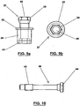
- Each of these implant holders 3 comprises firstly a set of composite form forming a mandrel 37 and secondly a fixing screw 38 of the implant 1. These two elements are respectively represented on the Figures 9 and 10 .
- the mandrel 37 has an upper portion 39 of hexagonal section forming a complementary piece of an instrument holder. This portion 39 has an axial bore 40 and is connected to a smooth sleeve 24 by a flange 22 identical to that of the drills 4,5.
- the base of the mandrel 37 comprises a cavity 41 of hexagonal section complementary to the hexagonal head 42, provided with a threaded blind hole, of an implant 1.
- the screw 38 passing through the mandrel 37 is screwed by means of its threaded end 43 into the hexagonal head 42 in order to make integral the implant 1 of the implant holder 3.
- the head of the screw 38 of the implant holder 3 is advantageously of the type with hexagon socket 44.
- the outer diameter of the sleeve 24 of the mandrel 37 corresponds to the inside diameter of a guiding cylinder 14.
- the implant 1 is guided during its implementation by the sliding of the sleeve 24 in the cylinder 14 of the jig 11.
- the flange 22 coming into abutment on the upper part of the cylinder 14 limits the depression to the level desired by the surgeon.
- washers 23 made of POM make it possible to precisely control this level of penetration.
- Implant holders 3 are divided into two main types according to their length: bone implant holders, short, and long implant holders, suitable for transmucosal placement.
- the outside diameter of the sleeve 24 of an implant holder 3 is 4.15 mm, which provides smooth sliding in a cylinder 14 having an internal diameter of 4.20 mm.
- the height of the sleeve 24 (height of the implant holder under the collar) is 4.5 mm for the bone implant holders, and 10.5 mm for the mucosal implant holders.
- the total length of the screw 38 of the implant holder 3 is respectively 13.5 mm and 19.5 mm.
- the sleeve 24 is respectively 10.0 mm and 15.0 mm high, and the screw 38 is 19.0 mm and 24.0 mm respectively. , 0 mm long.
- the hexagon socket 41 of the base of the mandrel 24 and the thread M2 43 of the screw 38 are compatible with most of the implants 1 on the market.
- the washers 23 of the implant holder 3 are made of the same biocompatible plastic material as the rings 21 of the drills 4,5.
- their outside diameter is that of the flanges 22, and their inside diameter is 4.10 mm, a diameter slightly smaller than the outside diameter of the sleeve 24.
- Their thickness is either 0.5 mm or 1, 5 mm.
- the thinnest are white and the thickest are black so as not to be confused.
- the method and the device described above may in some cases be simplified so as to no longer use ring 21 and / or washer 23 to adapt the penetration lengths of drills 4, 5 and, respectively, those of the door implants 3, regardless of the drilling depth, gum thickness or the level of insertion of the implants.
- the most frequently used implant lengths are: 8.5; 10; 11.5; 13; 15; 18 and 20 mm.
- X is equal to the length of the drill used or usable less the length of the implant to put in place, X must allow the use of an available implant holder, without ring or washer, by choosing X + 4 for length implant holder.
- this value X will be independent of the depression of the implant in the bone and its position relative to the bone crest, but also independent of the operating mode (bone guide or mucous guide), independent of the measurement of the bone. thickness of the gingiva and independent of the determination of the surface of the crest of the bone.
- Implant holder lengths of 4, 5, 6, 7, 9, 10, 11, 12, 13, 14 and 17 mm will in practice make it possible to respond to all the above-mentioned cases, that is to say avoid the use of a ring and / or the use of a washer.
Landscapes
- Health & Medical Sciences (AREA)
- Oral & Maxillofacial Surgery (AREA)
- Dentistry (AREA)
- Epidemiology (AREA)
- Life Sciences & Earth Sciences (AREA)
- Animal Behavior & Ethology (AREA)
- General Health & Medical Sciences (AREA)
- Public Health (AREA)
- Veterinary Medicine (AREA)
- Orthopedic Medicine & Surgery (AREA)
- Dental Prosthetics (AREA)
- Dental Tools And Instruments Or Auxiliary Dental Instruments (AREA)
- Prostheses (AREA)
Claims (16)
- Vorrichtung zum Einbringen von Zahnimplantaten (1), umfassend:a) eine Bohrschablone (11), die Bohrungen (15) von vorbestimmten Achsen und Positionen aufweist, die mit mindestens einem Führungszylinder (14) von vorbestimmter Abmessung ausgestattet sind,b) mindestens einen Implantathalter (3), bestehend aus:- einerseits einem Dorn (37), der nacheinander entlang seiner Achse Folgendes aufweist:= ein Stück (39), das komplementär zu einem Instrumentenhalter ist,= einen Kragen (22), der geeignet ist, in Anlage auf dem oberen Teil des Führungszylinders (14) zu kommen,= eine glatte Muffe (24) von einem einzigen vorbestimmten Standarddurchmesser, der dem Standard-Innendurchmesser der Hülsen (14) entspricht,= eine Form (41), die komplementär zu dem Standardkopf (42) der Implantate (1) ist, und- andererseits einer Schraube (38), die geeignet ist, den Dorn (37) zu durchqueren und in den Kopf (42) geschraubt zu werden.
- Vorrichtung zum Einbringen von Zahnimplantaten (1) nach Anspruch 1, die ferner einen Satz Scheiben (23) von einem Innendurchmesser aufweist, der dem Durchmesser des Implantathalters (3) entspricht, wobei die Scheiben (23) dazu bestimmt sind, um die glatte Muffe (24) von jedem der Implantathalter (3) eingefügt zu werden, um die Eindringtiefe zu kontrollieren.
- Vorrichtung zum Einbringen von Zahnimplantaten (1) nach einem der Ansprüche 1 bis 2, wobei der Implantathalter (3) eine vorbestimmte Standardlänge aufweist, unabhängig von der Höhe der einzubringenden Implantate (1), wodurch auf diese Weise universelle Implantathalter gebildet werden.
- Vorrichtung zum Einbringen von Zahnimplantaten (1) nach einem der vorhergehenden Ansprüche 1 bis 3, umfassend:a) eine Scanführung, die dazu bestimmt ist, in dem Mund des Patienten platziert zu werden,b) ein erstes System zum Erfassen auf Computer der Scannerdaten der Führung, und des Unterkiefers oder des Oberkiefers (7) des Patienten,c) ein zweites System zum Simulieren auf Computer des Unterkiefers oder des Oberkiefers (7) ausgehend von den Daten,d) ein drittes System zum Generieren durch den Computer von Implantatsplanungsparametern ausgehend von der Simulation,e) ein viertes System zum Bilden der Schablone (11), wobei dieses vierte System computersteuerbar ist,f) ein fünftes System zum Steuern durch den Computer ausgehend von den Parametern des vierten Systems,g) Bohrhülsen (18), die koaxial in dem oberen Teil (15) der Führungszylinder (14) angeordnet sind,h) Bohrer (4, 5) mit Durchmessern, die den Innendurchmessern der Hülsen (18) entsprechen, wobei die Hülsen (18) alle einen einzigen vorbestimmten Standard-Innendurchmesser aufweisen und die Bohrer (4, 5) einen ersten Satz von Stufenbohrern (4) und einen zweiten Satz von Kalibrierbohrern (5) aufweisen, wovon jeweils der Standard-Maximaldurchmesser und der Standard-Nenndurchmesser dem Innendurchmesser der Hülsen (18) entsprechen.
- Vorrichtung zum Einbringen von Zahnimplantaten (1) nach Anspruch 4, dadurch gekennzeichnet, dass jeder der Stufenbohrer (4) nacheinander nach seiner Achse von dem spitzen Ende zu dem anderen Ende Folgendes aufweist:- eine erste Bohrlänge (30) von einem einzigen Standarddurchmesser, der in Abhängigkeit von dem Typ der Implantate (1) vorbestimmt ist,- eine zweite Bohrlänge (31), die an die erste Bohrlänge (30) angrenzt, von einem einzigen vorbestimmten Standarddurchmesser, der größer als der Durchmesser der ersten Bohrlänge (30) ist,- einen glatten Teil (32) von einem einzigen vorbestimmten Standarddurchmesser, der dem Standard-Innendurchmesser der Hülsen (18) entspricht,- ein Kragen (22), und- ein Standard-Blockiermittel für ein Handstück (33).
- Vorrichtung zum Einbringen von Zahnimplantaten (1) nach einem der vorhergehenden Ansprüche 4 oder 5, dadurch gekennzeichnet, dass jeder der Kalibrierbohrer (5) nacheinander nach seiner Achse von dem spitzen Ende zu dem anderen Ende Folgendes aufweist:- eine erste Schnittlänge (34) von einem einzigen vorbestimmten Standarddurchmesser, der dem Standard-Innendurchmesser der Hülsen (18) entspricht,- eine zweite Schnittlänge (35) von einem Durchmesser, der im Wesentlichen niedriger als der Durchmesser der ersten Schnittlänge (34) ist,- einen glatten Bereich (36) von einem einzigen vorbestimmten Standarddurchmesser, der dem einzigen Innendurchmesser der Hülsen (18) entspricht,- ein Kragen (22) und- ein Standard-Blockiermittel für ein Handstück (33).
- Vorrichtung zum Einbringen von Zahnimplantaten (1) nach einem der vorhergehenden Ansprüche 4 bis 6, dadurch gekennzeichnet, dass die Bohrungen (15) von variablen Höhen sind, um ohne zusätzliches Mittel die Eindringtiefe der Bohrer (4, 5) in den Unterkiefer oder den Oberkiefer (7) zu begrenzen.
- Vorrichtung zum Einbringen von Zahnimplantaten (1) nach einem der vorhergehenden Ansprüche 5 oder 6, dadurch gekennzeichnet, dass sie ferner eine Anordnung von Ringen (21) von einem Innendurchmesser, der dem Durchmesser der Bohrer (4, 5) entspricht, aufweist, wobei die Ringe (21) dazu bestimmt sind, um den glatten Teil (32) oder den glatten Bereich (36) von jedem der Bohrer (4, 5) eingefügt zu werden, um die Eindringtiefe zu kontrollieren.
- Vorrichtung zum Einbringen von Zahnimplantaten (1) nach einem der vorhergehenden Ansprüche 5 oder 6, dadurch gekennzeichnet, dass die Stufenbohrer (4) und die Kalibrierbohrer (5) alle von einer einzigen Standardlänge sind, die in Abhängigkeit von dem Typ der Implantate (1) vorbestimmt ist, unahbängig von der Tiefe der zu erstellenden Löcher (17), wodurch auf diese Weise universelle Bohrer gebildet werden.
- Vorrichtung zum Einbringen von Zahnimplantaten (1) nach einem der vorhergehenden Ansprüche 4 bis 9, dadurch gekennzeichnet, dass die Zylinder (14) und die Hülsen (18) jeweils ein Innengewinde (25) und ein Außengewinde (26) aufweisen, die vier Schraubenlinien um 90° voneinander aufweisen.
- Vorrichtung zum Einbringen von Zahnimplantaten (1) nach einem der vorhergehenden Ansprüche 4 bis 10, dadurch gekennzeichnet, dass jede der Hülsen (18) einen Ring (27) aufweist, der eine tangentiale Öffnung (29) aufweist.
- Vorrichtung zum Einbringen von Zahnimplantaten (1) nach einem der vorhergehenden Ansprüche 4 bis 11, dadurch gekennzeichnet, dass jede der Hülsen (18) einen Ring (27) aufweist, der vier radiale Sacklöcher (28) um 90° voneinander aufweist.
- Vorrichtung zum Einbringen von Zahnimplantaten (1) nach einem der vorhergehenden Ansprüche 8 oder 11, dadurch gekennzeichnet, dass die Ringe (21) und die Scheiben (23) aus einem biokompatiblen Kunststoff, vorzugsweise aus Polyoxymethacrylat (POM), hergestellt sind.
- Vorrichtung zum Einbringen von Zahnimplantaten nach einem der vorhergehenden Ansprüche 1 bis 13, dadurch gekennzeichnet, dass die Zylinder (14) aus einer Titanlegierung, vorzugsweise TA6V, sind.
- Vorrichtung zum Einbringen von Zahnimplantaten (1) nach einem der vorhergehenden Ansprüche 4 bis 14, dadurch gekennzeichnet, dass Hülsen (18) aus Stahl, vorzugsweise aus INOX 316L, sind.
- Vorrichtung zum Einbringen von Zahnimplantaten (1) nach einem der vorhergehenden Ansprüche 1 bis 15, dadurch gekennzeichnet, dass der Dorn (37) aus einer Titanlegierung, vorzugsweise TA6V, ist.
Applications Claiming Priority (3)
| Application Number | Priority Date | Filing Date | Title |
|---|---|---|---|
| FR0202587 | 2002-02-28 | ||
| FR0202587A FR2836372B1 (fr) | 2002-02-28 | 2002-02-28 | Procede et dispositif pour la mise en place d'implants dentaires |
| PCT/FR2003/000667 WO2003071972A1 (fr) | 2002-02-28 | 2003-02-28 | Procede et dispositif pour la mise en place d'implants dentaires |
Publications (2)
| Publication Number | Publication Date |
|---|---|
| EP1478298A1 EP1478298A1 (de) | 2004-11-24 |
| EP1478298B1 true EP1478298B1 (de) | 2016-12-07 |
Family
ID=27676201
Family Applications (1)
| Application Number | Title | Priority Date | Filing Date |
|---|---|---|---|
| EP03722685.9A Expired - Lifetime EP1478298B1 (de) | 2002-02-28 | 2003-02-28 | Verfahren und vorrichtung zum einsetzen von zahnimplantaten |
Country Status (8)
| Country | Link |
|---|---|
| US (3) | US20050170311A1 (de) |
| EP (1) | EP1478298B1 (de) |
| JP (1) | JP4395375B2 (de) |
| KR (1) | KR100963365B1 (de) |
| AU (1) | AU2003229850A1 (de) |
| CA (1) | CA2477107C (de) |
| FR (1) | FR2836372B1 (de) |
| WO (1) | WO2003071972A1 (de) |
Families Citing this family (264)
| Publication number | Priority date | Publication date | Assignee | Title |
|---|---|---|---|---|
| SE522958C2 (sv) | 2000-12-29 | 2004-03-16 | Nobel Biocare Ab | Förfarande, arrangemang (anordning) och program vid eller för protetisk installation |
| DE60232316D1 (de) * | 2001-02-27 | 2009-06-25 | Smith & Nephew Inc | Vorrichtung zur totalen knierekonstruktion |
| SE520765C2 (sv) | 2001-12-28 | 2003-08-19 | Nobel Biocare Ab | Anordning och arrangemang för att medelst mall ta upp hål till implantat i ben, företrädesvis käkben |
| FR2836372B1 (fr) * | 2002-02-28 | 2004-06-04 | Obl | Procede et dispositif pour la mise en place d'implants dentaires |
| SE526666C2 (sv) * | 2002-12-30 | 2005-10-25 | Nobel Biocare Ab | Anordning och arrangemang för fixturinstallation |
| SE526665C2 (sv) * | 2002-12-30 | 2005-10-25 | Nobel Biocare Ab | Anordning vid dentalt fastskruvningsarrangemang |
| WO2004075771A1 (en) | 2003-02-28 | 2004-09-10 | Materialise, Naamloze Vennootschap | Method for placing and manufacturing a dental superstructure, method for placing implants and accessories used thereby |
| GB0327822D0 (en) * | 2003-12-01 | 2003-12-31 | Materialise Nv | Method for manufacturing a prosthesis made prior to implant placement |
| SE526223C2 (sv) | 2003-12-10 | 2005-08-02 | Nobel Biocare Ab | System och anordning vid framställning och isättning av tandbrouppbyggnad |
| US9050665B2 (en) | 2003-12-30 | 2015-06-09 | Greenberg Surgical Technologies, Llc | Modular template for drilling holes and method of making same |
| USRE47368E1 (en) | 2003-12-30 | 2019-04-30 | Greenberg Surgical Technologies, Llc | Modular template for drilling holes and method of making same |
| USD516214S1 (en) * | 2004-04-12 | 2006-02-28 | Brian Tang | Surgical template for dental implant |
| FR2869791B1 (fr) * | 2004-05-04 | 2006-06-09 | Obl Sa | Guide chirurgical implantaire sur mesure et fraise associee, leur procede de fabrication et leur utilisation |
| USD530011S1 (en) * | 2004-06-24 | 2006-10-10 | Brian Tang | Surgical template for distal extension |
| SE527504C2 (sv) | 2004-08-05 | 2006-03-21 | Nobel Biocare Ab | Styranordning samverkbar med ett antal i tandmall anordnade hylsor |
| SE527503C2 (sv) * | 2004-08-05 | 2006-03-21 | Nobel Biocare Ab | Anordning och förfarande för att underlätta applicering till rätt läge av tand- eller tandrestmall |
| US7322824B2 (en) * | 2004-08-17 | 2008-01-29 | Schmitt Stephen M | Design and manufacture of dental implant restorations |
| EP1791491A1 (de) * | 2004-09-14 | 2007-06-06 | Oratio B.V. | Verfahren zur herstellung und anbringung eines keramischen dentalimplantats mit einem ästhetischen implantatwiderlager |
| WO2006033482A1 (ja) * | 2004-09-24 | 2006-03-30 | Icat Corporation | 治療情報提供システム |
| WO2006127597A2 (en) | 2005-05-20 | 2006-11-30 | Greenberg Surgical Technologies, Llc | Modular template for drilling holes and method of making same |
| SE528724C2 (sv) * | 2005-06-03 | 2007-01-30 | Nobel Biocare Services Ag | Anordning vid i mun anordnad borrmall |
| US8185224B2 (en) | 2005-06-30 | 2012-05-22 | Biomet 3I, Llc | Method for manufacturing dental implant components |
| US7090495B1 (en) * | 2005-07-12 | 2006-08-15 | Dan Rosen | Dental implant screw and post system |
| ITBO20050545A1 (it) * | 2005-09-06 | 2007-03-07 | Federico Franchini | Serie di strumenti chirurgici per implantologia dentale |
| US11219511B2 (en) * | 2005-10-24 | 2022-01-11 | Biomet 3I, Llc | Methods for placing an implant analog in a physical model of the patient's mouth |
| US8257083B2 (en) | 2005-10-24 | 2012-09-04 | Biomet 3I, Llc | Methods for placing an implant analog in a physical model of the patient's mouth |
| WO2007077223A1 (en) * | 2006-01-06 | 2007-07-12 | Materialise Dental N.V. | Dental handpiece |
| US20090004625A1 (en) * | 2006-01-12 | 2009-01-01 | Alessio Esposti | Dental Drilling Assembly |
| US8043091B2 (en) | 2006-02-15 | 2011-10-25 | Voxelogix Corporation | Computer machined dental tooth system and method |
| US8366442B2 (en) | 2006-02-15 | 2013-02-05 | Bankruptcy Estate Of Voxelogix Corporation | Dental apparatus for radiographic and non-radiographic imaging |
| US8858561B2 (en) * | 2006-06-09 | 2014-10-14 | Blomet Manufacturing, LLC | Patient-specific alignment guide |
| US8591516B2 (en) | 2006-02-27 | 2013-11-26 | Biomet Manufacturing, Llc | Patient-specific orthopedic instruments |
| US8603180B2 (en) | 2006-02-27 | 2013-12-10 | Biomet Manufacturing, Llc | Patient-specific acetabular alignment guides |
| US7967868B2 (en) | 2007-04-17 | 2011-06-28 | Biomet Manufacturing Corp. | Patient-modified implant and associated method |
| US20150335438A1 (en) | 2006-02-27 | 2015-11-26 | Biomet Manufacturing, Llc. | Patient-specific augments |
| US8535387B2 (en) | 2006-02-27 | 2013-09-17 | Biomet Manufacturing, Llc | Patient-specific tools and implants |
| US9289253B2 (en) | 2006-02-27 | 2016-03-22 | Biomet Manufacturing, Llc | Patient-specific shoulder guide |
| US8864769B2 (en) | 2006-02-27 | 2014-10-21 | Biomet Manufacturing, Llc | Alignment guides with patient-specific anchoring elements |
| US9918740B2 (en) | 2006-02-27 | 2018-03-20 | Biomet Manufacturing, Llc | Backup surgical instrument system and method |
| US9907659B2 (en) | 2007-04-17 | 2018-03-06 | Biomet Manufacturing, Llc | Method and apparatus for manufacturing an implant |
| US8407067B2 (en) | 2007-04-17 | 2013-03-26 | Biomet Manufacturing Corp. | Method and apparatus for manufacturing an implant |
| US8568487B2 (en) | 2006-02-27 | 2013-10-29 | Biomet Manufacturing, Llc | Patient-specific hip joint devices |
| US8377066B2 (en) | 2006-02-27 | 2013-02-19 | Biomet Manufacturing Corp. | Patient-specific elbow guides and associated methods |
| US8241293B2 (en) | 2006-02-27 | 2012-08-14 | Biomet Manufacturing Corp. | Patient specific high tibia osteotomy |
| US9345548B2 (en) | 2006-02-27 | 2016-05-24 | Biomet Manufacturing, Llc | Patient-specific pre-operative planning |
| US10278711B2 (en) | 2006-02-27 | 2019-05-07 | Biomet Manufacturing, Llc | Patient-specific femoral guide |
| US8608749B2 (en) | 2006-02-27 | 2013-12-17 | Biomet Manufacturing, Llc | Patient-specific acetabular guides and associated instruments |
| US8133234B2 (en) * | 2006-02-27 | 2012-03-13 | Biomet Manufacturing Corp. | Patient specific acetabular guide and method |
| US9339278B2 (en) | 2006-02-27 | 2016-05-17 | Biomet Manufacturing, Llc | Patient-specific acetabular guides and associated instruments |
| US9173661B2 (en) | 2006-02-27 | 2015-11-03 | Biomet Manufacturing, Llc | Patient specific alignment guide with cutting surface and laser indicator |
| US8092465B2 (en) | 2006-06-09 | 2012-01-10 | Biomet Manufacturing Corp. | Patient specific knee alignment guide and associated method |
| US9113971B2 (en) | 2006-02-27 | 2015-08-25 | Biomet Manufacturing, Llc | Femoral acetabular impingement guide |
| US8608748B2 (en) | 2006-02-27 | 2013-12-17 | Biomet Manufacturing, Llc | Patient specific guides |
| FR2898485B1 (fr) * | 2006-03-15 | 2008-05-30 | Obl Sa | Dispositif de guidage d'un foret implantaire |
| JP4926237B2 (ja) * | 2006-03-30 | 2012-05-09 | フリアデント ゲーエムベーハー | インプラントを装着するための構造体 |
| ES2666492T3 (es) | 2006-05-04 | 2018-05-04 | Nobel Biocare Services Ag | Un dispositivo para fijar un implante dental en tejido óseo, un procedimiento para fabricar una plantilla quirúrgica y un procedimiento de fijación de un implante dental en tejido óseo |
| IL175477A (en) * | 2006-05-08 | 2013-09-30 | Efraim Kfir | A kit for lifting the sinus membranes for use in dental implant surgery |
| GB0609988D0 (en) * | 2006-05-19 | 2006-06-28 | Materialise Nv | Method for creating a personalized digital planning file for simulation of dental implant placement |
| US9795399B2 (en) | 2006-06-09 | 2017-10-24 | Biomet Manufacturing, Llc | Patient-specific knee alignment guide and associated method |
| EP1915970A1 (de) * | 2006-07-20 | 2008-04-30 | René De Clerck | Schablone zum Positionieren von Dentalimplantaten |
| US7653455B2 (en) * | 2006-07-28 | 2010-01-26 | 3M Innovative Properties Company | Computer-aided implanting of orthodontic anchorage devices using surgical guides |
| US20080051805A1 (en) * | 2006-08-28 | 2008-02-28 | Leonard Pinchuk | Hair Follicle Coring Tool and System Based Thereon |
| EP1894539A1 (de) * | 2006-09-04 | 2008-03-05 | Bio-Micron S.A.S. di Campetti Emilio | Bohrschablone für den Unterkiefer- oder den Oberkieferknochen |
| US7835811B2 (en) | 2006-10-07 | 2010-11-16 | Voxelogix Corporation | Surgical guides and methods for positioning artificial teeth and dental implants |
| EP1915969A1 (de) * | 2006-10-27 | 2008-04-30 | Straumann Holding AG | Dentalimplantat zur Abstützung einer Dentalprothese |
| EP2086451B1 (de) * | 2006-11-03 | 2017-02-08 | Dentsply Implants NV | Vorrichtung zur befestigung einer dentalen stütze auf einem implantat |
| FR2910804B1 (fr) | 2007-01-02 | 2010-03-12 | Michel Isidori | Dispositif de guidage et de modelage osseux pour la preparation de sites osseux en chirurgie |
| CN101578076B (zh) | 2007-01-10 | 2013-10-23 | 诺贝尔生物服务公司 | 用于牙设计和制备的方法和系统 |
| KR100811595B1 (ko) * | 2007-01-11 | 2008-03-11 | 조선대학교산학협력단 | 임플란트 식립위치 유도기 |
| EP2120775B1 (de) | 2007-01-26 | 2016-06-29 | DENTSPLY Implants Manufacturing GmbH | Anordnung mit einem instrument zur vorbereitung oder durchführung der insertion eines implantats |
| KR100881224B1 (ko) * | 2007-05-09 | 2009-02-05 | (주)이우테크놀로지 | 치과용 템플릿 및 이를 이용한 임플란트 이식 방법 |
| US9351744B2 (en) | 2007-05-14 | 2016-05-31 | Queen's University At Kingston | Patient-specific surgical guidance tool and method of use |
| EP2157926B1 (de) * | 2007-05-14 | 2015-04-22 | Queen's University At Kingston | Patientenspezifisches chirurgisches führungswerkzeug |
| US8206153B2 (en) | 2007-05-18 | 2012-06-26 | Biomet 3I, Inc. | Method for selecting implant components |
| EP2397102A1 (de) | 2007-08-22 | 2011-12-21 | Straumann Holding AG | Bohrerführung |
| JP5467726B2 (ja) * | 2007-09-12 | 2014-04-09 | イマグノーシス株式会社 | インプラント植立用穿孔器具、ハンドピース、ハンドピース用アダプタおよびサージカルガイド |
| US8265949B2 (en) | 2007-09-27 | 2012-09-11 | Depuy Products, Inc. | Customized patient surgical plan |
| US9138239B2 (en) | 2007-09-30 | 2015-09-22 | DePuy Synthes Products, Inc. | Customized patient-specific tibial cutting blocks |
| US8357111B2 (en) | 2007-09-30 | 2013-01-22 | Depuy Products, Inc. | Method and system for designing patient-specific orthopaedic surgical instruments |
| US9173662B2 (en) | 2007-09-30 | 2015-11-03 | DePuy Synthes Products, Inc. | Customized patient-specific tibial cutting blocks |
| WO2011106399A1 (en) | 2010-02-25 | 2011-09-01 | Depuy Products, Inc. | Customized patient-specific bone cutting blocks |
| EP2957243A1 (de) | 2007-09-30 | 2015-12-23 | DePuy Products, Inc. | Massgeschneidertes patientespezifisches orthopädisches chirurgisches instrument |
| US8100692B2 (en) * | 2007-10-19 | 2012-01-24 | Cagenix Incorporated | Dental framework |
| DE102007052389A1 (de) * | 2007-10-31 | 2009-05-07 | Sicat Gmbh & Co. Kg | Verfahren zur Herstellung einer Behandlungsschablone |
| US8777612B2 (en) * | 2007-11-16 | 2014-07-15 | Biomet 3I, Llc | Components for use with a surgical guide for dental implant placement |
| FR2925289B1 (fr) * | 2007-12-20 | 2011-01-21 | Anthogyr Sa | Dispositif de centrage et de guidage d'un foret de piece a main dentaire |
| ES2739460T3 (es) * | 2008-03-19 | 2020-01-31 | Nobel Biocare Services Ag | Reposicionamiento de componentes relacionados con procedimientos quirúrgicos craneales en un paciente |
| ES2683119T3 (es) | 2008-04-15 | 2018-09-25 | Biomet 3I, Llc | Método de creación de un modelo dental digital preciso de huesos y tejidos blandos |
| US8011927B2 (en) | 2008-04-16 | 2011-09-06 | Biomet 3I, Llc | Method for pre-operative visualization of instrumentation used with a surgical guide for dental implant placement |
| EP2296574A1 (de) * | 2008-05-09 | 2011-03-23 | Palti, Ady | Positionierhülse zum bohren mit einem chirurgischen bohrer und einer bohrschablone und system zum bohren |
| JP5165457B2 (ja) | 2008-05-21 | 2013-03-21 | 株式会社ジーシー | 歯科用ドリル用着脱式ストッパ |
| WO2010025191A1 (en) * | 2008-08-29 | 2010-03-04 | Zimmer Dental, Inc. | Dental drill guide system |
| DE202008012049U1 (de) * | 2008-09-10 | 2009-02-19 | Gäßler Zahntechnik GmbH | Zahnmedizinisches Bohrführungssystem |
| US8078440B2 (en) | 2008-09-19 | 2011-12-13 | Smith & Nephew, Inc. | Operatively tuning implants for increased performance |
| KR101027481B1 (ko) * | 2008-09-24 | 2011-04-08 | 이태경 | 임플란트 정밀식립용 드릴과 유도부싱 및 이를 이용한 임플란트 정밀식립 장치 |
| KR101019664B1 (ko) * | 2008-10-30 | 2011-03-07 | 이태경 | 임플란트 정밀유도식립 장치 |
| JP4942120B2 (ja) * | 2008-11-17 | 2012-05-30 | 株式会社若吉製作所 | 医療用切削具の案内具 |
| ES2552235T3 (es) * | 2008-12-01 | 2015-11-26 | Straumann Holding Ag | Manguito de taladro para un taladro dental |
| CH700105A2 (de) * | 2008-12-15 | 2010-06-15 | Straumann Holding Ag | Set von Dentalbohrern. |
| EP2196162B1 (de) | 2008-12-15 | 2016-10-12 | Straumann Holding AG | Bohrerführung |
| KR101124467B1 (ko) * | 2008-12-31 | 2012-03-15 | 주식회사 사이버메드 | 수술용 가이드 및 수술용 가이드 어셈블리 |
| KR101013390B1 (ko) * | 2008-12-31 | 2011-02-14 | 주식회사 사이버메드 | 임플란트 시술용 드릴링 템플릿 |
| WO2010076943A1 (ko) * | 2008-12-31 | 2010-07-08 | 주식회사 사이버메드 | 가이드 및 가이드를 이용하는 임플란트 식립의 설계 방법 |
| KR101013389B1 (ko) * | 2008-12-31 | 2011-02-14 | 주식회사 사이버메드 | 임플란트 시술용 드릴링 템플릿의 제조방법 |
| US8529255B2 (en) * | 2009-01-16 | 2013-09-10 | V2R Biomedical Inc | Dental prosthesis system |
| US9039414B2 (en) * | 2009-02-06 | 2015-05-26 | Scott E. Bulloch | Drill guide pin, shank, cannulated drill bit, and driver for creating a hole in a bone |
| US20100203479A1 (en) * | 2009-02-06 | 2010-08-12 | Bulloch Scott E | Dental implant system and methods |
| EP2254068B1 (de) | 2009-05-18 | 2020-08-19 | Nobel Biocare Services AG | Verfahren und System, die einen verbesserten Datenabgleich zur virtuellen Planung bereitstellen |
| DE102009031692B4 (de) * | 2009-06-26 | 2011-07-21 | DENTAURUM GmbH & Co. KG, 75228 | Zahnmedizinische Gewindeschneidanordnung |
| JP4971401B2 (ja) * | 2009-07-17 | 2012-07-11 | 株式会社アイキャット | ガイド固定ピン |
| DE102009028503B4 (de) | 2009-08-13 | 2013-11-14 | Biomet Manufacturing Corp. | Resektionsschablone zur Resektion von Knochen, Verfahren zur Herstellung einer solchen Resektionsschablone und Operationsset zur Durchführung von Kniegelenk-Operationen |
| WO2011027689A1 (ja) * | 2009-09-01 | 2011-03-10 | Akutsu Isao | インプラント用器具及びインプラント用器具のガイドシステム |
| ES2596828T3 (es) * | 2009-09-07 | 2017-01-12 | Nobel Biocare Services Ag | Componentes para el roscado guiado de un hueso |
| EP2292176B1 (de) | 2009-09-07 | 2019-01-09 | Nobel Biocare Services AG | Implantations-Set |
| WO2011037206A1 (ja) * | 2009-09-24 | 2011-03-31 | 株式会社アイキャット | ガイド固定ピンおよびこのガイド固定ピンを用いてインプラント手術を行う方法 |
| US8311791B1 (en) | 2009-10-19 | 2012-11-13 | Surgical Theater LLC | Method and system for simulating surgical procedures |
| JP2011087708A (ja) | 2009-10-21 | 2011-05-06 | Gc Corp | 歯科用テンプレート |
| US8348669B1 (en) | 2009-11-04 | 2013-01-08 | Bankruptcy Estate Of Voxelogix Corporation | Surgical template and method for positioning dental casts and dental implants |
| US20110111362A1 (en) * | 2009-11-11 | 2011-05-12 | Jerome Haber | Surgical guides |
| EP2322115B1 (de) * | 2009-11-16 | 2017-02-15 | Nobel Biocare Services AG | Verfahren zur Planung und Herstellung einer Zahnprothese |
| MX2012005649A (es) | 2009-11-17 | 2012-12-05 | Univ Kingston | Guia especifica de paciente para colocacion de la copa acetabular. |
| KR101122133B1 (ko) * | 2010-01-08 | 2012-03-20 | 주식회사 메가젠임플란트 | 임플란트 시술용 드릴 |
| JP2011152238A (ja) * | 2010-01-26 | 2011-08-11 | Akira Takebayashi | インプラント用ドリル |
| WO2011106407A1 (en) | 2010-02-25 | 2011-09-01 | Depuy Products, Inc. | Method of fabricating customized patient-specific bone cutting blocks |
| ES2704658T3 (es) | 2010-02-25 | 2019-03-19 | Depuy Products Inc | Bloques de corte de hueso específicos al paciente personalizados |
| US8632547B2 (en) * | 2010-02-26 | 2014-01-21 | Biomet Sports Medicine, Llc | Patient-specific osteotomy devices and methods |
| US9579106B2 (en) | 2010-03-31 | 2017-02-28 | New York Society For The Relief Of The Ruptured And Crippled, Maintaining The Hospital For Special Surgery | Shoulder arthroplasty instrumentation |
| JP5493171B2 (ja) * | 2010-04-20 | 2014-05-14 | デンツプライIh株式会社 | 外科用テンプレート位置決装置 |
| CA2798950C (en) * | 2010-09-21 | 2016-09-20 | Implantdent Co., Ltd. | Gauge body and method for preparing surgical guide |
| US9271744B2 (en) | 2010-09-29 | 2016-03-01 | Biomet Manufacturing, Llc | Patient-specific guide for partial acetabular socket replacement |
| TWI448276B (zh) * | 2010-11-26 | 2014-08-11 | Po Kun Cheng | 牙齒定位模板及其製造方法 |
| US9968376B2 (en) | 2010-11-29 | 2018-05-15 | Biomet Manufacturing, Llc | Patient-specific orthopedic instruments |
| DK2462893T3 (da) | 2010-12-07 | 2014-06-30 | Biomet 3I Llc | Universel scanningsdel til anvendelse på dentalimplantat og dentalimplantat-analoge |
| US9241745B2 (en) | 2011-03-07 | 2016-01-26 | Biomet Manufacturing, Llc | Patient-specific femoral version guide |
| DE202011004222U1 (de) | 2011-03-21 | 2012-06-25 | Bego Implant Systems Gmbh & Co. Kg | Bohrführungshülse für eine Zahnimplantat-Bohreinheit |
| EP2691946A4 (de) | 2011-03-30 | 2015-09-23 | Mordechai Avisar | Verfahren und system zur simulation chirurgischer eingriffe |
| ITPI20110040A1 (it) | 2011-04-08 | 2012-10-09 | Univ Pisa | Maschera di foratura per impiantare una vite transpeduncolare |
| US8715289B2 (en) | 2011-04-15 | 2014-05-06 | Biomet Manufacturing, Llc | Patient-specific numerically controlled instrument |
| US9675400B2 (en) | 2011-04-19 | 2017-06-13 | Biomet Manufacturing, Llc | Patient-specific fracture fixation instrumentation and method |
| US8668700B2 (en) | 2011-04-29 | 2014-03-11 | Biomet Manufacturing, Llc | Patient-specific convertible guides |
| US8956364B2 (en) | 2011-04-29 | 2015-02-17 | Biomet Manufacturing, Llc | Patient-specific partial knee guides and other instruments |
| GB201108078D0 (en) * | 2011-05-16 | 2011-06-29 | Materialise Nv | Surgical guides and methods for manufacturing thereof |
| JP5834136B2 (ja) | 2011-05-16 | 2015-12-16 | バイオメット・3アイ・エルエルシー | 仮の補綴物アセンブリ |
| US8532807B2 (en) | 2011-06-06 | 2013-09-10 | Biomet Manufacturing, Llc | Pre-operative planning and manufacturing method for orthopedic procedure |
| KR102801852B1 (ko) | 2011-06-08 | 2025-04-28 | 가부시키가이샤 한도오따이 에네루기 켄큐쇼 | 스퍼터링 타겟, 스퍼터링 타겟의 제조 방법 및 박막의 형성 방법 |
| US9084618B2 (en) | 2011-06-13 | 2015-07-21 | Biomet Manufacturing, Llc | Drill guides for confirming alignment of patient-specific alignment guides |
| US8641721B2 (en) | 2011-06-30 | 2014-02-04 | DePuy Synthes Products, LLC | Customized patient-specific orthopaedic pin guides |
| US8764760B2 (en) | 2011-07-01 | 2014-07-01 | Biomet Manufacturing, Llc | Patient-specific bone-cutting guidance instruments and methods |
| US20130001121A1 (en) | 2011-07-01 | 2013-01-03 | Biomet Manufacturing Corp. | Backup kit for a patient-specific arthroplasty kit assembly |
| FR2977142B1 (fr) * | 2011-07-01 | 2014-06-13 | Euroteknika | Dispositif pour la pose d'une prothese dentaire |
| ITFI20110130A1 (it) * | 2011-07-01 | 2013-01-02 | Leone Spa | Sistema di guida chirurgica per implantologia dentale e procedimento per la realizzazione di guide chirurgiche per implantologia dentale. |
| KR101199957B1 (ko) | 2011-07-04 | 2012-11-09 | 주식회사 메가젠임플란트 | 치과 임플란트용 수술가이드 제작 키트 |
| AU2012280708A1 (en) | 2011-07-06 | 2014-01-23 | Nobel Biocare Services Ag | Screw and driver tool |
| JP5855378B2 (ja) * | 2011-07-25 | 2016-02-09 | 京セラメディカル株式会社 | 歯科用穿孔ドリルキット |
| US8597365B2 (en) | 2011-08-04 | 2013-12-03 | Biomet Manufacturing, Llc | Patient-specific pelvic implants for acetabular reconstruction |
| US9295497B2 (en) | 2011-08-31 | 2016-03-29 | Biomet Manufacturing, Llc | Patient-specific sacroiliac and pedicle guides |
| US9066734B2 (en) | 2011-08-31 | 2015-06-30 | Biomet Manufacturing, Llc | Patient-specific sacroiliac guides and associated methods |
| JP2013066665A (ja) | 2011-09-26 | 2013-04-18 | Gc Corp | ストッパー及びストッパーセット |
| US9386993B2 (en) | 2011-09-29 | 2016-07-12 | Biomet Manufacturing, Llc | Patient-specific femoroacetabular impingement instruments and methods |
| KR20130046336A (ko) | 2011-10-27 | 2013-05-07 | 삼성전자주식회사 | 디스플레이장치의 멀티뷰 디바이스 및 그 제어방법과, 디스플레이 시스템 |
| US9451973B2 (en) | 2011-10-27 | 2016-09-27 | Biomet Manufacturing, Llc | Patient specific glenoid guide |
| US9554910B2 (en) | 2011-10-27 | 2017-01-31 | Biomet Manufacturing, Llc | Patient-specific glenoid guide and implants |
| US9301812B2 (en) | 2011-10-27 | 2016-04-05 | Biomet Manufacturing, Llc | Methods for patient-specific shoulder arthroplasty |
| ES2635542T3 (es) | 2011-10-27 | 2017-10-04 | Biomet Manufacturing, Llc | Guías glenoideas específicas para el paciente |
| KR101254028B1 (ko) * | 2011-10-27 | 2013-04-12 | 주식회사 메가젠임플란트 | 치과 임플란트 수술가이드를 위한 임플란트 마운트 및 임플란트 마운트의 분리방법 |
| JP2013102929A (ja) | 2011-11-14 | 2013-05-30 | Gc Corp | 人工歯根埋設用システム |
| TW201325563A (zh) * | 2011-12-16 | 2013-07-01 | Metal Ind Res & Dev Ct | 植牙導引裝置 |
| US9089382B2 (en) | 2012-01-23 | 2015-07-28 | Biomet 3I, Llc | Method and apparatus for recording spatial gingival soft tissue relationship to implant placement within alveolar bone for immediate-implant placement |
| US9452032B2 (en) | 2012-01-23 | 2016-09-27 | Biomet 3I, Llc | Soft tissue preservation temporary (shell) immediate-implant abutment with biological active surface |
| US9237950B2 (en) | 2012-02-02 | 2016-01-19 | Biomet Manufacturing, Llc | Implant with patient-specific porous structure |
| KR101457011B1 (ko) * | 2012-04-06 | 2014-11-04 | 오상훈 | 치과용 임플란트 고정구 천공 가이드 장치 및 이를 이용한 천공 방법 |
| ES2872298T3 (es) | 2012-05-25 | 2021-11-02 | Surgical Theater Inc | Renderizado híbrido de imágenes/escena con control de manos libres |
| US9999510B2 (en) * | 2012-06-05 | 2018-06-19 | Dental Vision B.V.B.A. | Method for manufacturing a template to adapt the shape of a bone defect in a jaw to a bone superstructure |
| JP5968120B2 (ja) * | 2012-06-27 | 2016-08-10 | 京セラメディカル株式会社 | 歯科インプラント用ステントの製造方法およびステント製造用補助具 |
| US9885108B2 (en) | 2012-08-07 | 2018-02-06 | Semiconductor Energy Laboratory Co., Ltd. | Method for forming sputtering target |
| GB201216224D0 (en) | 2012-09-12 | 2012-10-24 | Nobel Biocare Services Ag | An improved virtual splint |
| GB201216214D0 (en) | 2012-09-12 | 2012-10-24 | Nobel Biocare Services Ag | A digital splint |
| GB201216230D0 (en) | 2012-09-12 | 2012-10-24 | Nobel Biocare Services Ag | An improved surgical template |
| US20140080092A1 (en) | 2012-09-14 | 2014-03-20 | Biomet 3I, Llc | Temporary dental prosthesis for use in developing final dental prosthesis |
| US9687322B2 (en) | 2012-09-28 | 2017-06-27 | Robert P. Carmichael | Dental implant positioning system |
| JP6153721B2 (ja) * | 2012-11-15 | 2017-06-28 | 医療法人社団清友会 | ガイド治具 |
| US9204977B2 (en) | 2012-12-11 | 2015-12-08 | Biomet Manufacturing, Llc | Patient-specific acetabular guide for anterior approach |
| US9060788B2 (en) | 2012-12-11 | 2015-06-23 | Biomet Manufacturing, Llc | Patient-specific acetabular guide for anterior approach |
| US8920512B2 (en) | 2012-12-19 | 2014-12-30 | Biomet Sports Medicine, Llc | Method and apparatus for pre-forming a high tibial osteotomy |
| US8926328B2 (en) | 2012-12-27 | 2015-01-06 | Biomet 3I, Llc | Jigs for placing dental implant analogs in models and methods of doing the same |
| GB2509739A (en) | 2013-01-11 | 2014-07-16 | Nobel Biocare Services Ag | Dental drill bit with spherical head and helical fluting |
| DE202013000576U1 (de) | 2013-01-22 | 2014-04-23 | Bego Implant Systems Gmbh & Co. Kg | Hülsensystem für die schablonengeführte dentale Implantologie |
| DE202013001415U1 (de) | 2013-01-22 | 2013-03-05 | Bego Implant Systems Gmbh & Co. Kg | Hülsensystem für die schablonengeführte dentale Implantologie |
| KR101440213B1 (ko) | 2013-01-26 | 2014-09-15 | 이도상 | 임플란트용 시술기구 |
| KR101385882B1 (ko) * | 2013-02-06 | 2014-04-22 | 연세대학교 원주산학협력단 | 수술가이드를 이용한 치과 임플란트 시술에 사용되는 수술가이드용 유니버셜 임플란트 수술키트 |
| US10729520B2 (en) * | 2013-02-06 | 2020-08-04 | Biomet 3I, Llc | Method and drills for two stage protocol for creating an osteotomy for a dental implant |
| GB2511038A (en) * | 2013-02-20 | 2014-08-27 | Nobel Biocare Services Ag | Surgical template arrangement and method |
| JP6141777B2 (ja) | 2013-02-28 | 2017-06-07 | 株式会社半導体エネルギー研究所 | 半導体装置の作製方法 |
| US9839438B2 (en) | 2013-03-11 | 2017-12-12 | Biomet Manufacturing, Llc | Patient-specific glenoid guide with a reusable guide holder |
| US9579107B2 (en) | 2013-03-12 | 2017-02-28 | Biomet Manufacturing, Llc | Multi-point fit for patient specific guide |
| US9826981B2 (en) | 2013-03-13 | 2017-11-28 | Biomet Manufacturing, Llc | Tangential fit of patient-specific guides |
| US9498233B2 (en) | 2013-03-13 | 2016-11-22 | Biomet Manufacturing, Llc. | Universal acetabular guide and associated hardware |
| US9517145B2 (en) | 2013-03-15 | 2016-12-13 | Biomet Manufacturing, Llc | Guide alignment system and method |
| WO2015030652A1 (en) * | 2013-08-26 | 2015-03-05 | Elos Medtech Timmersdala Ab | Dental drill system |
| US10016255B2 (en) | 2013-08-26 | 2018-07-10 | Elos Medtech Timmersdala Ab | Dental surgery device |
| US20150112349A1 (en) | 2013-10-21 | 2015-04-23 | Biomet Manufacturing, Llc | Ligament Guide Registration |
| JP2015109889A (ja) * | 2013-12-06 | 2015-06-18 | エムアイエス インプランツ テクノロジーズ リミテッド | ガイド付きドリル、ガイド付きドリルのキット、および該キットを用いる歯科インプラント挿入のための骨切り術の方法 |
| EP3094283A4 (de) | 2013-12-20 | 2018-01-24 | Biomet 3i, LLC | Zahnärztliches system zur entwicklung von angepassten prothesen durch abtasten von codierten elementen |
| US9211165B2 (en) | 2014-03-19 | 2015-12-15 | GRS Guide System, Inc. | Positioning and installing surgical drilling devices and related devices and systems |
| US9113982B1 (en) | 2014-03-19 | 2015-08-25 | GRS Guide System, Inc. | Positioning and installing surgical drilling devices and related devices and systems |
| US9283055B2 (en) | 2014-04-01 | 2016-03-15 | FPJ Enterprises, LLC | Method for establishing drill trajectory for dental implants |
| CN105992996B (zh) | 2014-04-04 | 2019-11-26 | 外科手术室公司 | 外科手术环境中的动态和交互式导航 |
| KR101518171B1 (ko) * | 2014-04-17 | 2015-05-07 | 정유진 | 치과용 임플란트 수술 시에 사용되는 수술용구를 지지하는 탄성 지지대 |
| US10282488B2 (en) | 2014-04-25 | 2019-05-07 | Biomet Manufacturing, Llc | HTO guide with optional guided ACL/PCL tunnels |
| US10426711B2 (en) | 2014-05-08 | 2019-10-01 | Cagenix, Inc. | Dental implant framework |
| US10980618B2 (en) | 2014-05-08 | 2021-04-20 | Cagenix, Inc. | Dental framework and prosthesis |
| US9408616B2 (en) | 2014-05-12 | 2016-08-09 | Biomet Manufacturing, Llc | Humeral cut guide |
| US9561040B2 (en) | 2014-06-03 | 2017-02-07 | Biomet Manufacturing, Llc | Patient-specific glenoid depth control |
| US9839436B2 (en) | 2014-06-03 | 2017-12-12 | Biomet Manufacturing, Llc | Patient-specific glenoid depth control |
| US11553985B2 (en) | 2014-07-25 | 2023-01-17 | 3Shape A/S | Drill guide assembly |
| US9504534B2 (en) * | 2014-08-08 | 2016-11-29 | Vincent Prestipino | Apparatuses and methods for implanting dental implants |
| US9700390B2 (en) | 2014-08-22 | 2017-07-11 | Biomet 3I, Llc | Soft-tissue preservation arrangement and method |
| US10639132B2 (en) * | 2014-09-12 | 2020-05-05 | Italo Lozada | Dental prosthesis |
| EP2997931B1 (de) * | 2014-09-19 | 2019-12-11 | Cendres + Métaux SA | Instrument zur handhabung eines dentalteils |
| US9833245B2 (en) | 2014-09-29 | 2017-12-05 | Biomet Sports Medicine, Llc | Tibial tubercule osteotomy |
| US9826994B2 (en) | 2014-09-29 | 2017-11-28 | Biomet Manufacturing, Llc | Adjustable glenoid pin insertion guide |
| US10136968B2 (en) | 2014-12-24 | 2018-11-27 | Isethco Llc | Disposable surgical intervention guides, methods, and kits |
| US9962234B2 (en) * | 2014-12-24 | 2018-05-08 | Isethco Llc | Disposable surgical intervention guides, methods, and kits |
| KR101695006B1 (ko) * | 2015-02-26 | 2017-01-10 | 오스템임플란트 주식회사 | 임플란트 수술 가이드 장치 세트 |
| WO2016144970A1 (en) | 2015-03-09 | 2016-09-15 | Chu Stephen J | Gingival ovate pontic and methods of using the same |
| USRE49930E1 (en) * | 2015-03-26 | 2024-04-23 | Universidade De Coimbra | Methods and systems for computer-aided surgery using intra-operative video acquired by a free moving camera |
| US9820868B2 (en) | 2015-03-30 | 2017-11-21 | Biomet Manufacturing, Llc | Method and apparatus for a pin apparatus |
| US10504239B2 (en) | 2015-04-13 | 2019-12-10 | Universidade De Coimbra | Methods and systems for camera characterization in terms of response function, color, and vignetting under non-uniform illumination |
| JP6534559B2 (ja) * | 2015-04-30 | 2019-06-26 | 土佐エンタープライズ株式会社 | 歯科用ドリル |
| WO2016207728A1 (en) * | 2015-06-23 | 2016-12-29 | The Research Foundation For The State University Of New York | Multi-diameter drill bit |
| US10226262B2 (en) | 2015-06-25 | 2019-03-12 | Biomet Manufacturing, Llc | Patient-specific humeral guide designs |
| US10568647B2 (en) | 2015-06-25 | 2020-02-25 | Biomet Manufacturing, Llc | Patient-specific humeral guide designs |
| US10136902B2 (en) * | 2015-07-31 | 2018-11-27 | Warsaw Orthopedic, Inc. | Surgical instrument and method |
| BR112018007473A2 (pt) | 2015-10-14 | 2018-10-23 | Surgical Theater LLC | navegação cirúrgica de realidade aumentada |
| KR101837506B1 (ko) * | 2016-09-12 | 2018-03-12 | 오스템임플란트 주식회사 | 템플릿과 함께 사용하기 위한 치과용 평탄화 드릴 |
| WO2018156089A1 (en) * | 2017-02-24 | 2018-08-30 | Suriyan Nawakamon | Dental drilling device |
| US10722310B2 (en) | 2017-03-13 | 2020-07-28 | Zimmer Biomet CMF and Thoracic, LLC | Virtual surgery planning system and method |
| US20180263727A1 (en) * | 2017-03-15 | 2018-09-20 | Coredent Advancements, LLC | Surgical Guide and Associated Process for Dental Implants |
| RU177272U1 (ru) * | 2017-09-04 | 2018-02-14 | Павел Александрович Коледа | Хирургический шаблон для установки имплантатов |
| US10861236B2 (en) | 2017-09-08 | 2020-12-08 | Surgical Theater, Inc. | Dual mode augmented reality surgical system and method |
| DE102017130440A1 (de) * | 2017-12-19 | 2019-06-19 | Dentaurum Gmbh & Co. Kg | Führungshülse für Bohrer, Werkzeugset zum Einbringen der Führungshülse und Bohrset für die dentale Implantologie |
| FR3079131A1 (fr) * | 2018-03-23 | 2019-09-27 | Gencowatt | Dispositif d'assistance au forage d'un puits pour implant dentaire |
| DE102018210259A1 (de) * | 2018-06-22 | 2019-12-24 | Sirona Dental Systems Gmbh | Verfahren zur Konstruktion einer Bohrschablone |
| US11051829B2 (en) | 2018-06-26 | 2021-07-06 | DePuy Synthes Products, Inc. | Customized patient-specific orthopaedic surgical instrument |
| US11364101B2 (en) | 2018-12-03 | 2022-06-21 | Cagenix, Inc. | Dental implant framework |
| RU2698296C1 (ru) * | 2018-12-29 | 2019-08-23 | Общество с ограниченной ответственностью "Мегадента Клиник" | Способ фиксации хирургического шаблона для установки стоматологических имплантатов в беззубую верхнюю челюсть |
| WO2020157340A1 (en) * | 2019-02-01 | 2020-08-06 | Bien-Air Holding Sa | Method and tool for measuring osseous quality |
| EP3934560B1 (de) | 2019-03-08 | 2024-01-24 | Straumann Holding AG | Ein zahnärztliches bohrerführungssystem |
| EA037711B1 (ru) * | 2019-09-09 | 2021-05-13 | Анастасия Викторовна Филиппова | Индивидуальный шаблон для выполнения остеотомии челюсти и установки дентальных имплантатов с немедленной нагрузкой |
| ES2947474T3 (es) | 2020-02-24 | 2023-08-09 | Anthogyr Sa | Conjunto para cirugía dental guiada |
| RU199318U1 (ru) * | 2020-03-10 | 2020-08-26 | Димитрий Сергеевич Алёшин | Втулка для ориентации режущего инструмента при скуловой имплантации |
| IL294405B2 (en) | 2020-03-31 | 2026-03-01 | Istanbul Univ Rektorlugu | Guided Dental Implant Shield Cover |
| CN113648091A (zh) * | 2020-05-12 | 2021-11-16 | 概美科技有限公司 | 种植手机、导引组件及在牙床上钻种植体孔的方法 |
| RU2742448C1 (ru) * | 2020-06-03 | 2021-02-05 | Екатерина Александровна Ищенко | Способ хирургического доступа к ретенированным зубам |
| RU2769621C2 (ru) * | 2020-08-31 | 2022-04-04 | Общество с ограниченной ответственностью "Инновационно-Технологическая Компания Эндопринт" (ООО"Инновационно-Технологическая Компания Эндопринт") | Направляющий шаблон для хирургической стоматологии |
| IT202100007388A1 (it) * | 2021-03-25 | 2022-09-25 | Benedictis Gino De | Sistema per la valutazione di un posizionamento di un impianto dentale. |
| USD1091822S1 (en) * | 2021-06-23 | 2025-09-02 | DDS Company, Inc. | Fixation article |
| TWI772178B (zh) * | 2021-09-10 | 2022-07-21 | 陳俊龍 | 單次鑽鑿的整套植入組件 |
| CN113974876B (zh) * | 2021-11-02 | 2024-03-19 | 广西医科大学 | 一种螺纹种植体的钻针 |
| CL2022000072A1 (es) * | 2022-01-11 | 2022-08-19 | Brok Spa | Sistema y procedimiento simplificado para cirugía de implantes dentales guiadas por computador. |
| WO2023148410A1 (es) * | 2022-02-01 | 2023-08-10 | Tech Xika Ptt, S.L. | Método de fabricación de una férula o guía quirúrgica para la implantación de al menos un implante dental |
| KR102763433B1 (ko) * | 2022-04-25 | 2025-02-05 | 주식회사 모노리스 | 치아 임플란트 시술용 가이드, 그 제조 시스템 및 그 제조 방법 |
| WO2024259066A1 (en) * | 2023-06-14 | 2024-12-19 | Evollution Ip Holdings, Inc. | Guided dental surgical adapter with improved surgical adaptability to patient physiology |
| US20250204930A1 (en) * | 2023-08-30 | 2025-06-26 | Biomet 3I, Llc | Pointed countersink drill |
Family Cites Families (50)
| Publication number | Priority date | Publication date | Assignee | Title |
|---|---|---|---|---|
| CH611792A5 (de) * | 1975-02-12 | 1979-06-29 | Werner Lutz Koch | |
| US4872840A (en) * | 1987-07-15 | 1989-10-10 | Team Incorporated | Dental implant and method |
| US4988297A (en) * | 1988-03-01 | 1991-01-29 | Implant Innovations, Inc. | Alignment corrector for dental implants |
| US4955811A (en) * | 1988-06-23 | 1990-09-11 | Implant Innovations, Inc. | Non-rotational single-tooth prosthodontic restoration |
| US5133660A (en) * | 1989-08-07 | 1992-07-28 | Fenick Thomas J | Device for locating the optimum position for a tooth implant |
| US5562448A (en) * | 1990-04-10 | 1996-10-08 | Mushabac; David R. | Method for facilitating dental diagnosis and treatment |
| US5743916A (en) * | 1990-07-13 | 1998-04-28 | Human Factors Industrial Design, Inc. | Drill guide with removable ferrules |
| US5184926A (en) * | 1990-11-05 | 1993-02-09 | Megatool, Inc. | Root-strength drill bit and method of making |
| US5102271A (en) * | 1991-02-25 | 1992-04-07 | Hemmings David T | Collet-wear reducing drill bit |
| SE469159B (sv) * | 1991-03-27 | 1993-05-24 | Nobelpharma Ab | Cylinder avsedd att anvaendas i en temporaer, implantatstoedd tandbro/tandprotes |
| US5215460A (en) * | 1991-11-20 | 1993-06-01 | Perry William L | Method for paralleling implant restorative components |
| US5213502A (en) * | 1992-06-10 | 1993-05-25 | Fereidoun Daftary | Interlockable two-piece impression coping for anatomical dental abutment restorative systems |
| US5320529A (en) | 1992-09-09 | 1994-06-14 | Howard C. Weitzman | Method and apparatus for locating an ideal site for a dental implant and for the precise surgical placement of that implant |
| US5338196A (en) * | 1993-04-08 | 1994-08-16 | Implant Innovations, Inc. | Dental laboratory components and procedures for anatomical restoration on artificial root fixtures |
| SE500851C2 (sv) * | 1993-04-28 | 1994-09-19 | Medevelop Ab | Protessystem för rehabilitering av tandlöshet |
| IT1270942B (it) * | 1993-05-14 | 1997-05-26 | Antonio Cascione | Dima radiografico-chirurgica orientabile per ipianti nelle ossa mascellari. |
| SE501661C2 (sv) * | 1993-08-26 | 1995-04-10 | Nobelpharma Ab | Metod vid avtryckstagning och framställning av käkbensförankrade tandproteser |
| US5662473A (en) * | 1993-12-02 | 1997-09-02 | Vident | Adjustable-angulation pattern for making a dental-implant abutment |
| US5492471A (en) * | 1994-03-23 | 1996-02-20 | Gary Singer | Healing cap system |
| BE1008372A3 (nl) | 1994-04-19 | 1996-04-02 | Materialise Nv | Werkwijze voor het vervaardigen van een geperfektioneerd medisch model uitgaande van digitale beeldinformatie van een lichaamsdeel. |
| US5685714A (en) * | 1994-06-16 | 1997-11-11 | Implant Innovations, Inc. | Support post for use in dental implant system |
| US5520688A (en) * | 1994-07-20 | 1996-05-28 | Lin; Chih-I | Vertebral auxiliary fixation device |
| US5613852A (en) * | 1995-01-06 | 1997-03-25 | Board Of Regents Univ Of Ne At Lincoln | Dental implant drill guide system |
| IL112989A (en) * | 1995-03-14 | 1998-06-15 | Avi Shampanier | Implant for an artificial tooth |
| FR2734707B1 (fr) * | 1995-05-30 | 1997-08-29 | Guedj Leon | Equipement chirurgical d'implantologie dentaire et elements, implant dentaire et instruments de forage, constitutifs |
| US5733122A (en) * | 1995-05-31 | 1998-03-31 | Gordon; Basil | Dental implant attachment assembly including device and method for resisting loosening of attachment |
| US5725376A (en) * | 1996-02-27 | 1998-03-10 | Poirier; Michel | Methods for manufacturing a dental implant drill guide and a dental implant superstructure |
| US6382975B1 (en) * | 1997-02-26 | 2002-05-07 | Technique D'usinage Sinlab Inc. | Manufacturing a dental implant drill guide and a dental implant superstructure |
| US6814575B2 (en) * | 1997-02-26 | 2004-11-09 | Technique D'usinage Sinlab Inc. | Manufacturing a dental implant drill guide and a dental implant superstructure |
| IL118371A (en) * | 1996-05-22 | 2000-06-29 | Conley Roy | Drill guide |
| US5823778A (en) * | 1996-06-14 | 1998-10-20 | The United States Of America As Represented By The Secretary Of The Air Force | Imaging method for fabricating dental devices |
| SE506850C2 (sv) * | 1996-06-27 | 1998-02-16 | Medevelop Ab | Tandprotessystem, komponenter för tandprotessystem jämte förfaranden vid dylika tandprotessystem |
| US5989258A (en) * | 1997-09-16 | 1999-11-23 | Hattori; Morihiro | Apparatus for and method of bone drilling |
| US5967777A (en) * | 1997-11-24 | 1999-10-19 | Klein; Michael | Surgical template assembly and method for drilling and installing dental implants |
| US6514258B1 (en) * | 1998-11-04 | 2003-02-04 | Implant Innovations, Inc. | Penetration limiting stop elements for a drill bit used for bone tissue |
| EP1171054B1 (de) * | 1999-04-15 | 2007-06-06 | Nobel Biocare AB | Mit diamantähnlichem kohlenstoff überzogene zahnärztliche halterungschraube |
| US6062856A (en) * | 1999-05-05 | 2000-05-16 | Sussman; Harold I. | Dental implant hole guide extension |
| DE29917458U1 (de) * | 1999-10-04 | 1999-12-23 | Lindner, Wolfram, Dr., 53844 Troisdorf | Aufsatz zur Festlegung der Eindringtiefe eines Bohrers (Tiefenmarkierungsring) |
| DE19952962B4 (de) * | 1999-11-03 | 2004-07-01 | Sirona Dental Systems Gmbh | Verfahren zur Herstellung einer Bohrhilfe für ein Zahnimplantat |
| US6672870B2 (en) * | 2001-03-20 | 2004-01-06 | John G. Knapp | Method and instrumentation for attaching dentures |
| US6361537B1 (en) * | 2001-05-18 | 2002-03-26 | Cinci M. Anderson | Surgical plate with pawl and process for repair of a broken bone |
| DE10159683A1 (de) * | 2001-11-30 | 2003-06-18 | Michael Gahlert | Dantalimplantat |
| US6692254B1 (en) * | 2002-02-01 | 2004-02-17 | Barry A. Kligerman | Implant supported dental prosthesis foundation bar |
| FR2836372B1 (fr) * | 2002-02-28 | 2004-06-04 | Obl | Procede et dispositif pour la mise en place d'implants dentaires |
| US7014461B2 (en) * | 2003-01-23 | 2006-03-21 | Tactile Technologies Llc | Hard tissue surface geometry determination |
| WO2004075771A1 (en) * | 2003-02-28 | 2004-09-10 | Materialise, Naamloze Vennootschap | Method for placing and manufacturing a dental superstructure, method for placing implants and accessories used thereby |
| GB0327822D0 (en) * | 2003-12-01 | 2003-12-31 | Materialise Nv | Method for manufacturing a prosthesis made prior to implant placement |
| TWI300580B (en) * | 2004-11-04 | 2008-09-01 | Nec Lcd Technologies Ltd | Method of processing substrate and chemical used in the same (1) |
| US20060275736A1 (en) * | 2005-04-22 | 2006-12-07 | Orthoclear Holdings, Inc. | Computer aided orthodontic treatment planning |
| GB0609988D0 (en) * | 2006-05-19 | 2006-06-28 | Materialise Nv | Method for creating a personalized digital planning file for simulation of dental implant placement |
-
2002
- 2002-02-28 FR FR0202587A patent/FR2836372B1/fr not_active Expired - Lifetime
-
2003
- 2003-02-28 CA CA2477107A patent/CA2477107C/en not_active Expired - Lifetime
- 2003-02-28 JP JP2003570720A patent/JP4395375B2/ja not_active Expired - Fee Related
- 2003-02-28 AU AU2003229850A patent/AU2003229850A1/en not_active Abandoned
- 2003-02-28 WO PCT/FR2003/000667 patent/WO2003071972A1/fr not_active Ceased
- 2003-02-28 EP EP03722685.9A patent/EP1478298B1/de not_active Expired - Lifetime
- 2003-02-28 KR KR1020047013405A patent/KR100963365B1/ko not_active Expired - Fee Related
- 2003-02-28 US US10/505,846 patent/US20050170311A1/en not_active Abandoned
-
2009
- 2009-04-10 US US12/421,919 patent/US20100009314A1/en not_active Abandoned
-
2011
- 2011-07-22 US US13/188,577 patent/US20110275032A1/en not_active Abandoned
Also Published As
| Publication number | Publication date |
|---|---|
| CA2477107C (en) | 2012-03-20 |
| US20050170311A1 (en) | 2005-08-04 |
| KR100963365B1 (ko) | 2010-06-14 |
| FR2836372A1 (fr) | 2003-08-29 |
| FR2836372B1 (fr) | 2004-06-04 |
| WO2003071972A1 (fr) | 2003-09-04 |
| KR20040101247A (ko) | 2004-12-02 |
| US20100009314A1 (en) | 2010-01-14 |
| AU2003229850A1 (en) | 2003-09-09 |
| US20110275032A1 (en) | 2011-11-10 |
| EP1478298A1 (de) | 2004-11-24 |
| JP2005518834A (ja) | 2005-06-30 |
| JP4395375B2 (ja) | 2010-01-06 |
| CA2477107A1 (en) | 2003-09-04 |
Similar Documents
| Publication | Publication Date | Title |
|---|---|---|
| FR2836372A1 (fr) | Procede et dispositif pour la mise en place d'implants dentaires | |
| EP1753365B1 (de) | Massgefertigte implantierbare chirurgische führung und zugehöriges fräswerkzeug und herstellungsverfahren | |
| WO2007104842A1 (fr) | Dispositif de guidage d'un foret implantaire et procede de pose d'un implant axial mettant en œuvre ce dispositif | |
| BE1016374A3 (fr) | Procede de fabrication d'une prothese dentaire et appareillage mis en oeuvre. | |
| EP1333771B1 (de) | Positionierungsvorrichtung zum einsetzen von implantatgetragene zahnprothesen | |
| EP2120772B1 (de) | Knochenmodellierung und führungsvorrichtung zur vorbereitung von knochenstellen zur implantatsoperation | |
| WO2000074585A2 (fr) | Dispositif de securite comportant une butee pour outil de forage utilisable notamment en chirurgie dentaire et dispositif de precalibrage et de memorisation de la profondeur de forage | |
| US20090286197A1 (en) | GRS implant drilling guide | |
| EP1478301A1 (de) | Instrument zur vorbereitung von knochenmaterial, verwendbar insbesondere in der zahntechnik und vorrichtung zu seiner verwendung | |
| US20160081765A1 (en) | A precision surical guidance tool system and delivery method for implementing dental implants | |
| CN106061428A (zh) | 用于牙植入外科手术的钻孔工具,包括阶梯状引导件 | |
| FR2653989A1 (fr) | Implant dentaire, outillage et procede de mise en place. | |
| EP2544621A1 (de) | Anordnung eines zahnimplantats und prothesenelement | |
| FR2943242A1 (fr) | Implant dentaire et ensemble prothetique comprenant un tel implant. | |
| EP1397086A1 (de) | Verfahren zur herstellung eines trägergerüstes einer zahnprothese, chirurgische bohrlehre und trägergerüst | |
| US20150313692A1 (en) | Methods and tooling for dental implant | |
| FR2516784A1 (fr) | Nouvel implant, outil pour la mise en place de celui-ci et procede de realisations implantaires | |
| TW201912128A (zh) | 製造具備有角度的內貫通孔的假牙的方法 | |
| WO2019180673A1 (fr) | Dispositif d'assistance au forage d'un puits pour implant dentaire | |
| RU2373892C2 (ru) | Способ протезирования зубов на имплантатах с применением стекловолоконной опорной головки и ее устройство | |
| US20080124672A1 (en) | Dental implant drill guide with handle | |
| WO2023007334A1 (fr) | Implant dentaire | |
| RU2250091C1 (ru) | Внутрикорневой штифтовой зуб | |
| JP2022045825A (ja) | 上顎洞底拳上器具 |
Legal Events
| Date | Code | Title | Description |
|---|---|---|---|
| PUAI | Public reference made under article 153(3) epc to a published international application that has entered the european phase |
Free format text: ORIGINAL CODE: 0009012 |
|
| 17P | Request for examination filed |
Effective date: 20040907 |
|
| AK | Designated contracting states |
Kind code of ref document: A1 Designated state(s): AT BE BG CH CY CZ DE DK EE ES FI FR GB GR HU IE IT LI LU MC NL PT SE SI SK TR |
|
| AX | Request for extension of the european patent |
Extension state: AL LT LV MK RO |
|
| RAP1 | Party data changed (applicant data changed or rights of an application transferred) |
Owner name: MATERIALISE DENTAL N.V. |
|
| 17Q | First examination report despatched |
Effective date: 20070621 |
|
| RAP1 | Party data changed (applicant data changed or rights of an application transferred) |
Owner name: DENTSPLY IMPLANTS NV |
|
| GRAJ | Information related to disapproval of communication of intention to grant by the applicant or resumption of examination proceedings by the epo deleted |
Free format text: ORIGINAL CODE: EPIDOSDIGR1 |
|
| GRAP | Despatch of communication of intention to grant a patent |
Free format text: ORIGINAL CODE: EPIDOSNIGR1 |
|
| GRAP | Despatch of communication of intention to grant a patent |
Free format text: ORIGINAL CODE: EPIDOSNIGR1 |
|
| GRAJ | Information related to disapproval of communication of intention to grant by the applicant or resumption of examination proceedings by the epo deleted |
Free format text: ORIGINAL CODE: EPIDOSDIGR1 |
|
| GRAP | Despatch of communication of intention to grant a patent |
Free format text: ORIGINAL CODE: EPIDOSNIGR1 |
|
| INTG | Intention to grant announced |
Effective date: 20160608 |
|
| INTG | Intention to grant announced |
Effective date: 20160623 |
|
| GRAS | Grant fee paid |
Free format text: ORIGINAL CODE: EPIDOSNIGR3 |
|
| STAA | Information on the status of an ep patent application or granted ep patent |
Free format text: STATUS: GRANT OF PATENT IS INTENDED |
|
| GRAA | (expected) grant |
Free format text: ORIGINAL CODE: 0009210 |
|
| STAA | Information on the status of an ep patent application or granted ep patent |
Free format text: STATUS: THE PATENT HAS BEEN GRANTED |
|
| AK | Designated contracting states |
Kind code of ref document: B1 Designated state(s): AT BE BG CH CY CZ DE DK EE ES FI FR GB GR HU IE IT LI LU MC NL PT SE SI SK TR |
|
| REG | Reference to a national code |
Ref country code: GB Ref legal event code: FG4D Free format text: NOT ENGLISH |
|
| REG | Reference to a national code |
Ref country code: CH Ref legal event code: EP Ref country code: AT Ref legal event code: REF Ref document number: 851052 Country of ref document: AT Kind code of ref document: T Effective date: 20161215 |
|
| REG | Reference to a national code |
Ref country code: IE Ref legal event code: FG4D Free format text: LANGUAGE OF EP DOCUMENT: FRENCH |
|
| REG | Reference to a national code |
Ref country code: DE Ref legal event code: R096 Ref document number: 60349684 Country of ref document: DE |
|
| REG | Reference to a national code |
Ref country code: FR Ref legal event code: PLFP Year of fee payment: 15 |
|
| REG | Reference to a national code |
Ref country code: SE Ref legal event code: TRGR |
|
| REG | Reference to a national code |
Ref country code: NL Ref legal event code: MP Effective date: 20161207 |
|
| PG25 | Lapsed in a contracting state [announced via postgrant information from national office to epo] |
Ref country code: GR Free format text: LAPSE BECAUSE OF FAILURE TO SUBMIT A TRANSLATION OF THE DESCRIPTION OR TO PAY THE FEE WITHIN THE PRESCRIBED TIME-LIMIT Effective date: 20170308 |
|
| REG | Reference to a national code |
Ref country code: AT Ref legal event code: MK05 Ref document number: 851052 Country of ref document: AT Kind code of ref document: T Effective date: 20161207 |
|
| PG25 | Lapsed in a contracting state [announced via postgrant information from national office to epo] |
Ref country code: BE Free format text: LAPSE BECAUSE OF NON-PAYMENT OF DUE FEES Effective date: 20170228 Ref country code: FI Free format text: LAPSE BECAUSE OF FAILURE TO SUBMIT A TRANSLATION OF THE DESCRIPTION OR TO PAY THE FEE WITHIN THE PRESCRIBED TIME-LIMIT Effective date: 20161207 Ref country code: ES Free format text: LAPSE BECAUSE OF FAILURE TO SUBMIT A TRANSLATION OF THE DESCRIPTION OR TO PAY THE FEE WITHIN THE PRESCRIBED TIME-LIMIT Effective date: 20161207 |
|
| PG25 | Lapsed in a contracting state [announced via postgrant information from national office to epo] |
Ref country code: NL Free format text: LAPSE BECAUSE OF FAILURE TO SUBMIT A TRANSLATION OF THE DESCRIPTION OR TO PAY THE FEE WITHIN THE PRESCRIBED TIME-LIMIT Effective date: 20161207 |
|
| PG25 | Lapsed in a contracting state [announced via postgrant information from national office to epo] |
Ref country code: CZ Free format text: LAPSE BECAUSE OF FAILURE TO SUBMIT A TRANSLATION OF THE DESCRIPTION OR TO PAY THE FEE WITHIN THE PRESCRIBED TIME-LIMIT Effective date: 20161207 Ref country code: SK Free format text: LAPSE BECAUSE OF FAILURE TO SUBMIT A TRANSLATION OF THE DESCRIPTION OR TO PAY THE FEE WITHIN THE PRESCRIBED TIME-LIMIT Effective date: 20161207 Ref country code: EE Free format text: LAPSE BECAUSE OF FAILURE TO SUBMIT A TRANSLATION OF THE DESCRIPTION OR TO PAY THE FEE WITHIN THE PRESCRIBED TIME-LIMIT Effective date: 20161207 |
|
| PG25 | Lapsed in a contracting state [announced via postgrant information from national office to epo] |
Ref country code: PT Free format text: LAPSE BECAUSE OF FAILURE TO SUBMIT A TRANSLATION OF THE DESCRIPTION OR TO PAY THE FEE WITHIN THE PRESCRIBED TIME-LIMIT Effective date: 20170407 Ref country code: BG Free format text: LAPSE BECAUSE OF FAILURE TO SUBMIT A TRANSLATION OF THE DESCRIPTION OR TO PAY THE FEE WITHIN THE PRESCRIBED TIME-LIMIT Effective date: 20170307 Ref country code: AT Free format text: LAPSE BECAUSE OF FAILURE TO SUBMIT A TRANSLATION OF THE DESCRIPTION OR TO PAY THE FEE WITHIN THE PRESCRIBED TIME-LIMIT Effective date: 20161207 |
|
| REG | Reference to a national code |
Ref country code: DE Ref legal event code: R097 Ref document number: 60349684 Country of ref document: DE |
|
| PG25 | Lapsed in a contracting state [announced via postgrant information from national office to epo] |
Ref country code: MC Free format text: LAPSE BECAUSE OF FAILURE TO SUBMIT A TRANSLATION OF THE DESCRIPTION OR TO PAY THE FEE WITHIN THE PRESCRIBED TIME-LIMIT Effective date: 20161207 |
|
| PLBE | No opposition filed within time limit |
Free format text: ORIGINAL CODE: 0009261 |
|
| STAA | Information on the status of an ep patent application or granted ep patent |
Free format text: STATUS: NO OPPOSITION FILED WITHIN TIME LIMIT |
|
| 26N | No opposition filed |
Effective date: 20170908 |
|
| REG | Reference to a national code |
Ref country code: IE Ref legal event code: MM4A |
|
| PG25 | Lapsed in a contracting state [announced via postgrant information from national office to epo] |
Ref country code: SI Free format text: LAPSE BECAUSE OF FAILURE TO SUBMIT A TRANSLATION OF THE DESCRIPTION OR TO PAY THE FEE WITHIN THE PRESCRIBED TIME-LIMIT Effective date: 20161207 Ref country code: DK Free format text: LAPSE BECAUSE OF FAILURE TO SUBMIT A TRANSLATION OF THE DESCRIPTION OR TO PAY THE FEE WITHIN THE PRESCRIBED TIME-LIMIT Effective date: 20161207 |
|
| PG25 | Lapsed in a contracting state [announced via postgrant information from national office to epo] |
Ref country code: LU Free format text: LAPSE BECAUSE OF NON-PAYMENT OF DUE FEES Effective date: 20170228 |
|
| REG | Reference to a national code |
Ref country code: FR Ref legal event code: PLFP Year of fee payment: 16 |
|
| REG | Reference to a national code |
Ref country code: BE Ref legal event code: MM Effective date: 20170228 |
|
| PG25 | Lapsed in a contracting state [announced via postgrant information from national office to epo] |
Ref country code: IE Free format text: LAPSE BECAUSE OF NON-PAYMENT OF DUE FEES Effective date: 20170228 |
|
| PG25 | Lapsed in a contracting state [announced via postgrant information from national office to epo] |
Ref country code: HU Free format text: LAPSE BECAUSE OF FAILURE TO SUBMIT A TRANSLATION OF THE DESCRIPTION OR TO PAY THE FEE WITHIN THE PRESCRIBED TIME-LIMIT; INVALID AB INITIO Effective date: 20030228 |
|
| PG25 | Lapsed in a contracting state [announced via postgrant information from national office to epo] |
Ref country code: CY Free format text: LAPSE BECAUSE OF NON-PAYMENT OF DUE FEES Effective date: 20161207 |
|
| PG25 | Lapsed in a contracting state [announced via postgrant information from national office to epo] |
Ref country code: TR Free format text: LAPSE BECAUSE OF FAILURE TO SUBMIT A TRANSLATION OF THE DESCRIPTION OR TO PAY THE FEE WITHIN THE PRESCRIBED TIME-LIMIT Effective date: 20161207 |
|
| PGFP | Annual fee paid to national office [announced via postgrant information from national office to epo] |
Ref country code: IT Payment date: 20210112 Year of fee payment: 19 Ref country code: FR Payment date: 20210113 Year of fee payment: 19 Ref country code: CH Payment date: 20210217 Year of fee payment: 19 |
|
| PGFP | Annual fee paid to national office [announced via postgrant information from national office to epo] |
Ref country code: DE Payment date: 20210216 Year of fee payment: 19 Ref country code: SE Payment date: 20210210 Year of fee payment: 19 Ref country code: GB Payment date: 20210217 Year of fee payment: 19 |
|
| REG | Reference to a national code |
Ref country code: DE Ref legal event code: R119 Ref document number: 60349684 Country of ref document: DE |
|
| REG | Reference to a national code |
Ref country code: CH Ref legal event code: PL |
|
| GBPC | Gb: european patent ceased through non-payment of renewal fee |
Effective date: 20220228 |
|
| PG25 | Lapsed in a contracting state [announced via postgrant information from national office to epo] |
Ref country code: FR Free format text: LAPSE BECAUSE OF NON-PAYMENT OF DUE FEES Effective date: 20220228 |
|
| PG25 | Lapsed in a contracting state [announced via postgrant information from national office to epo] |
Ref country code: SE Free format text: LAPSE BECAUSE OF NON-PAYMENT OF DUE FEES Effective date: 20220301 Ref country code: LI Free format text: LAPSE BECAUSE OF NON-PAYMENT OF DUE FEES Effective date: 20220228 Ref country code: GB Free format text: LAPSE BECAUSE OF NON-PAYMENT OF DUE FEES Effective date: 20220228 Ref country code: DE Free format text: LAPSE BECAUSE OF NON-PAYMENT OF DUE FEES Effective date: 20220901 Ref country code: CH Free format text: LAPSE BECAUSE OF NON-PAYMENT OF DUE FEES Effective date: 20220228 |
|
| PG25 | Lapsed in a contracting state [announced via postgrant information from national office to epo] |
Ref country code: IT Free format text: LAPSE BECAUSE OF NON-PAYMENT OF DUE FEES Effective date: 20220228 |