EP2292176B1 - Implantations-Set - Google Patents
Implantations-Set Download PDFInfo
- Publication number
- EP2292176B1 EP2292176B1 EP09011435.6A EP09011435A EP2292176B1 EP 2292176 B1 EP2292176 B1 EP 2292176B1 EP 09011435 A EP09011435 A EP 09011435A EP 2292176 B1 EP2292176 B1 EP 2292176B1
- Authority
- EP
- European Patent Office
- Prior art keywords
- thread
- implant
- thread forming
- bone
- section
- Prior art date
- Legal status (The legal status is an assumption and is not a legal conclusion. Google has not performed a legal analysis and makes no representation as to the accuracy of the status listed.)
- Active
Links
- 238000002513 implantation Methods 0.000 title 1
- 239000007943 implant Substances 0.000 claims description 154
- 210000000988 bone and bone Anatomy 0.000 claims description 91
- 230000005494 condensation Effects 0.000 claims description 7
- 238000009833 condensation Methods 0.000 claims description 7
- 230000037431 insertion Effects 0.000 claims 1
- 238000003780 insertion Methods 0.000 claims 1
- 230000003466 anti-cipated effect Effects 0.000 description 8
- 238000000034 method Methods 0.000 description 8
- 238000001356 surgical procedure Methods 0.000 description 5
- 238000005553 drilling Methods 0.000 description 3
- 230000000007 visual effect Effects 0.000 description 3
- 238000009827 uniform distribution Methods 0.000 description 2
- 239000000853 adhesive Substances 0.000 description 1
- 230000001070 adhesive effect Effects 0.000 description 1
- 230000006835 compression Effects 0.000 description 1
- 238000007906 compression Methods 0.000 description 1
- 230000001054 cortical effect Effects 0.000 description 1
- 230000007812 deficiency Effects 0.000 description 1
- 239000004053 dental implant Substances 0.000 description 1
- 230000001419 dependent effect Effects 0.000 description 1
- 238000010883 osseointegration Methods 0.000 description 1
Images


Classifications
-
- A—HUMAN NECESSITIES
- A61—MEDICAL OR VETERINARY SCIENCE; HYGIENE
- A61C—DENTISTRY; APPARATUS OR METHODS FOR ORAL OR DENTAL HYGIENE
- A61C8/00—Means to be fixed to the jaw-bone for consolidating natural teeth or for fixing dental prostheses thereon; Dental implants; Implanting tools
- A61C8/0089—Implanting tools or instruments
-
- A—HUMAN NECESSITIES
- A61—MEDICAL OR VETERINARY SCIENCE; HYGIENE
- A61C—DENTISTRY; APPARATUS OR METHODS FOR ORAL OR DENTAL HYGIENE
- A61C8/00—Means to be fixed to the jaw-bone for consolidating natural teeth or for fixing dental prostheses thereon; Dental implants; Implanting tools
-
- A—HUMAN NECESSITIES
- A61—MEDICAL OR VETERINARY SCIENCE; HYGIENE
- A61B—DIAGNOSIS; SURGERY; IDENTIFICATION
- A61B17/00—Surgical instruments, devices or methods, e.g. tourniquets
- A61B17/16—Bone cutting, breaking or removal means other than saws, e.g. Osteoclasts; Drills or chisels for bones; Trepans
- A61B17/1655—Bone cutting, breaking or removal means other than saws, e.g. Osteoclasts; Drills or chisels for bones; Trepans for tapping
-
- A—HUMAN NECESSITIES
- A61—MEDICAL OR VETERINARY SCIENCE; HYGIENE
- A61C—DENTISTRY; APPARATUS OR METHODS FOR ORAL OR DENTAL HYGIENE
- A61C1/00—Dental machines for boring or cutting ; General features of dental machines or apparatus, e.g. hand-piece design
- A61C1/08—Machine parts specially adapted for dentistry
-
- A—HUMAN NECESSITIES
- A61—MEDICAL OR VETERINARY SCIENCE; HYGIENE
- A61C—DENTISTRY; APPARATUS OR METHODS FOR ORAL OR DENTAL HYGIENE
- A61C3/00—Dental tools or instruments
-
- A—HUMAN NECESSITIES
- A61—MEDICAL OR VETERINARY SCIENCE; HYGIENE
- A61C—DENTISTRY; APPARATUS OR METHODS FOR ORAL OR DENTAL HYGIENE
- A61C3/00—Dental tools or instruments
- A61C3/02—Tooth drilling or cutting instruments; Instruments acting like a sandblast machine
-
- A—HUMAN NECESSITIES
- A61—MEDICAL OR VETERINARY SCIENCE; HYGIENE
- A61C—DENTISTRY; APPARATUS OR METHODS FOR ORAL OR DENTAL HYGIENE
- A61C8/00—Means to be fixed to the jaw-bone for consolidating natural teeth or for fixing dental prostheses thereon; Dental implants; Implanting tools
- A61C8/0018—Means to be fixed to the jaw-bone for consolidating natural teeth or for fixing dental prostheses thereon; Dental implants; Implanting tools characterised by the shape
- A61C8/0022—Self-screwing
-
- A—HUMAN NECESSITIES
- A61—MEDICAL OR VETERINARY SCIENCE; HYGIENE
- A61C—DENTISTRY; APPARATUS OR METHODS FOR ORAL OR DENTAL HYGIENE
- A61C1/00—Dental machines for boring or cutting ; General features of dental machines or apparatus, e.g. hand-piece design
- A61C1/08—Machine parts specially adapted for dentistry
- A61C1/082—Positioning or guiding, e.g. of drills
- A61C1/084—Positioning or guiding, e.g. of drills of implanting tools
Definitions
- This invention pertains in general to the field of implant surgery. More particularly, the invention relates to a combination of thread forming tool and an implant.
- the components may be used separately or in a system for drill and implant guided surgery.
- the implant In certain clinical applications when the implant is placed, such as placement in a jawbone, the implant has a tendency to deviate from its anticipated trajectory, for example due to varying density of the bone surrounding the implant, both in the vertical as well as the lateral direction of the implant. If, for example, the bone is denser one side of the central longitudinal axis of the implant, it will deviate towards the softer bone, and end up in a non-optimal position, which is different from a planned position. If this happens during guided surgery, the implant mount, which is guided by a guide sleeve of the surgical template, may jam in the guide sleeve.
- implant types are wider at the coronal end than at the apical end.
- the increase in width from the apical to the coronal end can be of two types, a) a substantially cylindrical implant with a wider coronal platform, or b) a tapered implant tapering from its apical end at least partially towards its coronal end.
- Such tapered implants sometimes tend to deviate from the anticipated path of trajectory. This is especially true for so called bone-condensing implants (type b) above), wherein the diameter of the implants may be gradually larger than the recess formed in the bone.
- an improved combination of components for placement of an implant would be advantageous and in particular allowing for improved precision, increased flexibility, cost-effectiveness, and/or patient safety would be advantageous.
- embodiments of the present invention preferably seek to mitigate, alleviate or eliminate one or more deficiencies, disadvantages or issues in the art, such as the above-identified, singly or in any combination by providing combination of components for placement of an implant according to the appended patent claims.
- the dimension of the thread forming section may be the radius from the central longitudinal axis of the thread forming tool to an external surface of a tip of its thread.
- the dimension of the thread of the implant may be the radius from the central longitudinal axis of the implant to an external surface of a tip of its thread.
- the dimension of the thread forming section may be the radius from the central longitudinal axis of the thread forming tool to an external surface of a root of its thread.
- the dimension of the thread of the implant may be the radius from the central longitudinal axis of the implant to an external surface of a root of its thread.
- a pitch of the helical thread of the thread forming section may be substantially equal to a pitch of the helical thread of the implant.
- the thread forming section is at least partially tapering outwardly from its apical end towards its coronal end.
- An apical portion of the implant is at least partially tapering outwardly from its apical end towards its coronal end.
- a maximum diameter of at least an apical portion of the bone tissue apposition surface is equal to a maximum diameter of the thread forming section of the thread forming tool.
- a maximum diameter of an apical portion of the bone apposition surface may be larger than a maximum diameter of an apical portion of the thread forming section of the thread forming tool, and smaller than a coronal portion of the thread forming section of the thread forming tool.
- a maximum diameter of a coronal portion of the bone tissue apposition surface may be larger than a maximum diameter of a coronal portion of the thread forming section of the thread forming tool.
- the combination may further comprise a drill, and a guide sleeve for a surgical template.
- the guide sleeve may have a guide surface for guiding the thread forming tool.
- the drill may have at least one cutting edge on the apical section and the coronal section.
- the thread forming tool may have a guide section for guidance by the guide surface of the guide sleeve.
- the thread forming section may comprise an apical portion, and a coronal portion. A maximum diameter of the apical portion of the thread forming section may be smaller than or equal to a maximum diameter of the cutting edge of the drill.
- a position of the maximum diameter of the apical portion of the thread forming section may be located offset from an apical end of the thread forming section.
- the position may also be located at a first distance from an apical end of the guide section.
- the first distance may be substantially equal to a second distance from said position to a coronal end of the guide surface when the thread forming tool is inserted into the guide sleeve.
- the offset may be at least 1 mm, preferably at least 2mm, for example in the range of 2-3mm.
- An apical end of the thread forming section may be larger than a maximum diameter of an apical section of the drill, which is smaller than a maximum diameter of a coronal section of the drill.
- Some embodiments of the invention provide for improved accuracy of a position of an implant in bone. Furthermore, embodiments of the invention provide for a relatively uniform distribution of load from the implant to the bone when the implant is placed. Hence, this provides for placement of the implant in an anticipated trajectory, i.e. the implant does not deviate from the anticipated trajectory. Hence, the implant may be more accurately centered within a recess of the bone, whereby more uniformly condensing of the bone around the periphery of the threads of the implant is provided for.
- Embodiments of the invention provide for reducing or eliminating one or several of an angular, a vertical, a centering, and/or a lateral deviation compared to an anticipated and/or planned position of the implant.
- Embodiments of the invention also provide for using bone-condensing implants, such as implants tapering outwards from its apical end towards its coronal end, in guided implant surgery and/or in hard bone applications.
- Components according to embodiments of the invention provides for passively inserting an implant in bone at least initially when it is placed.
- Passively threading means in the context of the invention that the implant can be inserted, such as by hand, to a certain depth without condensing the bone.
- the implant may contact the bone, but substantially not condense.
- a passive fit between the implant and the bone is provided. This provides for the implant more closely following an anticipated trajectory. Additionally or alternatively, a more uniform compression of bone when the implant is placed may be obtained, which in it self may contribute to that the implant follows the anticipated trajectory.
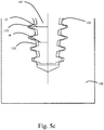
- Fig. 5a-5c illustrates some embodiments of the invention, wherein longitudinal cross/sectional views of an implant 101 and a thread forming tool 107 are overlaid.
- the thread forming tool 107 comprises a thread forming section 112 with a helical thread 130 having at least one cutting surface for cutting a thread in bone 102.
- the implant 101 comprises a bone apposition surface 123 having at least one helical thread 131 for position at least partially in a thread of the bone 102.
- a longitudinal cross-sectional shape of at least a portion of the helical thread 130 of the thread forming section substantially corresponds to a longitudinal cross-sectional shape of at least a portion of the helical thread 131 of the implant 101. This provides for substantially uniform distribution of load from the implant 101 to the bone 103 when the implant is inserted. This may, in turn, additionally provide for a more predictable path of trajectory when the implant 101 is placed in the bone 102.
- the longitudinal cross-sectional shape of the helical thread 130, 131 of the thread forming section 112 and the implant, respectively, may comprise the thread profile including the root of the thread, the tip of the thread, and the thread flank extending between the root of the thread to the tip of the thread.
- the tip of the threads 130, 131 comprises a flat face.
- the flat face may vary in width in the axial direction of the thread 130, 131.
- the root of the thread 130, 131 may form a substantially flat surface having a width.
- the shape of the root of the thread may be constant in the axial direction of the thread.
- Each of the tip, root, and/or flank of the thread may comprise at least one recess in the micrometer range for promotion of osseointegration.
- a dimension of the cross-sectional shape of the helical thread 130 of the thread forming section 112 substantially corresponds to a corresponding dimension of the cross-sectional shape of the helical thread 131 of the implant 101.
- the dimension of the cross-sectional shape of the helical thread 130 of the thread forming section 120 is smaller than a corresponding dimension of the cross-sectional shape of the helical thread 131 of the implant 101. The smaller the dimension is, the more condensing of the bone may be provided for. Hence, for applications in harder bone the difference of the dimensions may be smaller than for applications in softer bone.
- the dimension of the thread forming section 112 and the implant 101 are measured when they are aligned in a position which is their optimal final position, such as is illustrated in Figs. 5a-5c .
- the dimension may than be measured at a lateral cross section of the threaded section 112 and the implant 101 which is located at the same distance from the coronal end of the implant 101.
- the dimensions are measured when the threaded section 112 is vertically aligned with the implant 101 and the threads 130, 131 are rotationally aligned, i.e. the threads uniformly overlap.
- the dimension of the thread forming section 112 is a radius r1 ( Fig.
- the corresponding dimension of the thread 131 of the implant 101 is a radius r2 ( fig. 5c ) from the central longitudinal axis of the implant to an external surface of a tip 133 of its thread 131 for a lateral cross section taken at the same distance, as for measuring r1, from the coronal end of the implant 101.
- the dimension of the thread forming section 112 is a radius r3 (Fig. R3) from the central longitudinal axis of the thread forming tool 112 to an external surface of a root 134 of its thread.
- a corresponding dimension of the thread 131 of the implant 101 is a radius r4 ( Fig. 5c ) from the central longitudinal axis of the implant 101 to an external surface of a root 135 of its thread.
- the dimensions for the root are measured in the same way as for the dimension for the tips 132,133, as described above.
- a pitch of the helical thread 130 of the thread forming section 112 is substantially equal to a pitch of the helical thread 131 of the implant 101.
- the pitch is the distance from the crest of the thread to the next crest when the thread is viewed in longitudinal cross section.
- the threads 130, 131 of the threaded section 112 and the implant 101, respectively may be single or multiple lead threads.
- the thread forming section 112 is at least partially tapering outwardly from its apical end towards its coronal end.
- an apical portion, such as the entire or a portion of the threaded section of the implant 101, of the implant 101 is least partially tapering outwardly from its apical end towards its coronal end.
- either or both of the tip 133 and the root 135 of the thread 131 of the implant taper relative the central longitudinal axis of the implant 101.
- the tip 133 is substantially cylindrical and at least a portion of the root 135 of the thread 131 in the axial direction of the helical thread of the implant 101 taper relative the central longitudinal axis of the implant 101.
- the level of taper of the tip or crest 133 of the thread 131 has been indicated by straight lines 136a, 136b interconnecting a number of tip sections along various portions of the thread along the longitudinal axis of the implant 101.
- the level of taper of the root 135 of the thread 131 has been indicated by straight lines 137a, 137b interconnecting a number of root sections along various portions of the thread 131 along the longitudinal axis of the implant 101.
- the level of taper at the coronal end of the implant 101 compared to the apical end of the implant is less for both the tip 133 and root 135.
- Each root section may also taper more than the general taper of a number of subsequent root sections. This provides for improved bone-condensing properties, which is described in more detail in WO2004103202 and WO2008/128757 .
- the thread 131 of the thread forming section 112 may have the same general taper as the thread 131 of the implant 101.
- a maximum diameter of at least an apical portion of the bone tissue apposition surface 123 is smaller than or equal to a maximum diameter of the thread forming section 112 of the thread forming tool 107. This provides for passively threading the implant at least to a certain extent before condensing of the bone commences.
- the passively threading may correspond to the offset O discussed below.
- a maximum diameter of an apical portion of the bone apposition surface 123 is larger than a maximum diameter of an apical portion of the thread forming section of the thread forming tool, and smaller than a coronal portion of the thread forming section of the thread forming tool.
- a maximum diameter of a coronal portion of the bone tissue apposition surface is larger than a maximum diameter of a coronal portion of the thread forming section of the thread forming tool. This provides for condensation of the bone at least at the coronal portion of the implant 101, whereby improved stability can be obtained as well as a more controlled trajectory.
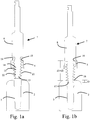
- Figs. 1a-1d illustrate a procedure for providing a threading in bone in a procedure for guided surgery.
- the embodiments described below can be combined with the embodiments described above.
- the threading may comprise one or several threads 3a depending on the type of implant 1 being installed, such as an implant having a single or multiple lead thread.
- the bone 2 is a jawbone.
- the guide sleeve 5 may be provided in the surgical template 6 as a separate or integrated component. Hence, the guide sleeve 5 may be integrated into or form part of the surgical template 6.
- the guide sleeve is a metallic cylindrical sleeve which has been fixed to the surgical template 6, e.g. using an adhesive.
- the guide sleeve 5 is detachable and can be inserted into a recess formed in the surgical template 6.
- the guide sleeve 5 has a guide surface 10 and a reference surface 11. The guide surface provides guidance to the drill 4a, 4b, 4c and/or the thread forming tool 7.
- the reference surface 11 can be used as the reference from which one or several depths or vertical directions are controlled.
- a coronal end surface of the guide sleeve 5 serves as the reference surface.
- the reference surface 11 has a fixed relationship relative to the planned position of the implant. Hence, by knowing the type and length of the implant 1, the depth of the recess 3 can be calculated, the correct depth drilled, and thread 3a provided at appropriate depth.
- the depth of any of the tooling can be controlled by markings on the tooling, such as visual or mechanical markings.
- a visual marking is for example a circumferential band indicating the distance to the tip of the tooling.
- a mechanical marking is for example a stop flange provided for abutment against the reference surface 11.
- the thread forming tool 7 has a thread forming section 12 for forming at least one thread in bone. Also, the thread forming tool 7 comprises the guide section 8 for guidance by the guide surface 10 of the guide sleeve 5.
- the thread forming section 12 comprises an apical portion 13, and a coronal portion 14. The exact delimitation of the apical portion 13 and the coronal portion 14 may depend on the length of the entire thread forming section 12, which in turn may depend on the length and/or type of implant to be installed. However, a maximum diameter of the apical portion 13 of the thread forming section 12 is smaller than or equal to a maximum diameter of a cutting edge 15a, 15b, 15c of the drill 4a, 4b, 4c.
- the maximum diameter of the recess 3 will correspond to the maximum diameter of the cutting edge 15a, 15b, 15c of the drill 4a, 4b, 4c.
- the maximum diameter of the apical portion 13 of the thread forming section 12 is smaller than or equal to the maximum diameter of the cutting edge 15a, 15b, 15c of the drill 4a, 4b, 4c, the apical portion of the thread forming section 12 will be received within the recess 3 without condensing the bone 2. How long the apical portion 13 is received depends on the exact configuration of the apical portion 13 and the recess 3.
- the thread forming section 12 After a certain distance, the thread forming section 12 starts contacting the bone because it has a larger diameter than the recess 3, whereby threads are formed in the bone 2.
- positional control such as centering, lateral, vertical, and/or angular control, of the thread forming section 12, is provided for.
- the recess 3 is stepped with a plurality of substantially circular cylindrical portions interconnected by a plurality of tapered portions.
- the recess 3 is substantially circular cylindrical, tapered, or a combination thereof, which may be formed by a correspondingly shaped drill 4a, 4b, 4c or plurality of drills.
- Fig. 1b illustrates an embodiment wherein a position 16 of the maximum diameter of the apical portion 13 of the thread forming section 12 is located offset O from an apical end 17 of the thread forming section 12.
- the position 16 is also located at a first distance d1 from an apical end 18 of the guide section 8.
- the first distance d1 is substantially equal to a second distance d2, which is equal to the distance from the position 16 to a coronal end 19 of the guide surface 10 when the thread forming tool 7 is inserted into the guide sleeve 5.
- the coronal end 19 of the guide surface 10 is located level with the reference surface 11.
- This embodiment provides for guidance by the guide sleeve 5 to the guide section 8 before the threaded section 12 engages the bone and starts generating the thread 3a in the bone 2.
- improved accuracy of the position of the thread 3a are provided for, such as improved angular, vertical, centering, and/or lateral control of the thread forming tool 7, and thus inherently improved accuracy of the position in space of the thread 3a in the bone 2.
- the offset O is at least 1 mm. In other embodiments, the offset is at least 2mm or even at least 3 mm.
- the offset O may be in the range of 2-3mm.
- the length of the offset O depends on the type of implant being installed and/or of the shape and dimension of the thread 3a that is to be provided in the bone 2. It may also depend on the length of the thread forming section 12.
- the apical end 17 of the thread forming section 12 is larger than a maximum diameter of an apical section 20a, 20b, 20c of the drill 4a, 4b, 4c.
- the apical section 20a, 20b, 20c of the drill may be smaller than a maximum diameter of a coronal section 21 of the drill 4a, 4b, 4c, such as for stepped drill or a tapered drill. This provides for providing threads in the recess along the entire length of the thread forming section 12.
- the apical end 17 of the thread forming section 12 is smaller than or equal to a diameter of the apical section 20a, 20b, 20c of the drill 4a, 4b, 4c where the apical end 17 of the thread forming tool 7 is located when it is inserted to its final depth, which is illustrated in Fig. 1c .
- This provides for improved stability of the implant when it is inserted, e.g. if the implant 1 has a thread cutting tip which provides threads while it is inserted to its full depth.
- the thread 3a provided in the coronal portion of the recess 3 controls the position of the implant 1.
- a diameter of the guide section 8 of the thread forming tool 7 is slightly smaller than a diameter of the guide surface of the guide sleeve, such as approximately 10-200 ⁇ m, for example 30-100 ⁇ m. This provides for the control of the trajectory of the thread forming tool 7, as discussed above.
- the apical portion 13 of the thread forming section 12 may at least partially taper outwardly from the apical end 12 towards the coronal end of the thread forming section.
- the entire thread forming section is tapering outwardly from its apical end to its coronal end.
- the gradual increase can be interrupted and instead a section with a generally cylindrical thread at the tip 21, the root 22, and/or in-between is provided.
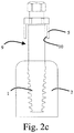
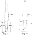
- Figs. 2a-2c illustrates the implant 1 and a procedure for placing the implant 1.
- the implant 1 has a bone tissue apposition surface 23, i.e. a surface that is in apposition to the bone 2 when the implant 1 is placed at its final position.
- a maximum diameter of at least an apical portion 24 of the bone tissue apposition surface 23 is smaller than or equal to a maximum diameter of the thread forming section 12 of the thread forming tool 7.
- Passively threading means in the context of the invention that the implant can be inserted, such as by hand, to a certain depth substantially without condensing the bone.
- the thread 3 rather than the guide sleeve 5 may guide the implant, as will be discussed in more detail below.
- the implant it is enough if the implant can be screwed one or two full revolutions, depending on the type of thread, such as lead and/or pitch, how coarse the thread is, the number of leads, etc.
- a maximum diameter of the apical portion 24 of the bone tissue apposition surface 23 is larger than a maximum diameter of the apical portion 13 of the thread forming section 12 of the thread forming tool 7. This provides for improved stability of the implant, such as if the implant condenses the bone at least at the apical portion 24.
- the length of the thread of the thread forming section 12 measured in the longitudinal direction of the thread forming tool 7 substantially corresponds to the length of the thread of the implant 1 measured in the longitudinal direction of the implant 1.
- the recess 3 is threaded substantially to its full depth.
- the length of the thread of the thread forming section 12 measured in the longitudinal direction of the thread forming tool 7 is shorter, such as at least 1 to 3mm, than the length of the thread of the implant 1 measured in the longitudinal direction of the implant 1.
- the recess 3 is threaded only partially to its full depth. The latter embodiment provides for improved stability of the implant 1, such as if the implant condenses the bone and/or even cuts its own thread in the bone at the apical end 24.
- a maximum diameter of a coronal portion 25 of the bone tissue apposition surface 23 is larger than a maximum diameter of the coronal portion 14 of the thread forming section 12 of the thread forming tool 7. This provides for condensation of the bone also at the coronal region of the bone tissue apposition surface, such as to provide improved contact with cortical bone.
- the implant mount 9 comprises a shank 26 with tool engaging head 27.
- the tool engaging head 27 has in this embodiment a hexagonal shape.
- the implant mount has a depth indicator 28 indicating the appropriate depth of the implant.
- the depth indicator is a tactile indicator, such as a flange, which provides tactile feedback to the user when the implant has reached its final or planner depth.
- the tactile feedback is e.g. provided when the flange abuts the reference surface 11 of the guide sleeve 5.
- the depth indicator 28 may provide visual feedback, such as a visible marking, e.g. a circumferential band, in the shank 26.
- Figs. 2a-2c clearance is provided between the guide surface 10 of the guide sleeve 5 and the shank 26.
- the guide surface 10 does not provide any guidance to the implant mount. Instead, guidance is provided by the thread 3a cut in the bone 2, such as lateral, centering, and/or angular guidance. This prevents that the implant mount 9 is jammed in the guide sleeve 5 and/or that the entire surgical template 6 is dislocated from its accurate position. Hence, improved positional accuracy is provided for, not only for the implant 1 that is actually being installed, but also for any additional implants being installed using the same surgical template 6.
- At least one of an apical section and a coronal section of the drill is substantially cylindrical, such as circular cylindrical, tapered, or cylindrical and taped.
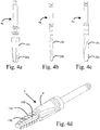
- Figs. 4a-4c illustrates various drills 4a, 4b, 4c for forming the recess 3 in the bone 2.
- Each drill 4a, 4b, 4c has at least one cutting edge 15a, 15b, 15c for cutting the recess 3a in the bone 2.
- the drill 4a of the embodiment of Fig. 4a is at least partially tapered, i.e. its cutting edge 15a forms substantially a circular cylinder at a coronal portion of the edge and tapered cone or truncated cone at an apical portion of the cutting edge 15a.
- the tapered portion may be in the range of 20-80% of the total length of the cutting edge 15a measured in the axial direction of the drill 4a.
- the drill 4b of the embodiment of Fig. 4b is substantially cylindrical.
- the cutting edge 15b of the cylindrical drill 4b is helical with a constant outer diameter.
- the drill 4c of the embodiment of Fig. 4c is a stepped drill, wherein the out diameter of the cutting edge 15c varies along the axial direction of the drill 4c.
- the edge as such is helical.
- the diameter of the cutting edge relative the longitudinal central axis of the drill 4c at the apical portion 20c is smaller than the diameter of the coronal portion of the drill.
- Fig. 4d illustrates an embodiment of the thread forming tool 7.
- the thread 130 of the thread forming tool 7 is helical and interrupted by at least one cutting surface 15d on each revolution of the thread 130 around the perimeter of the thread forming section.
- a recess 138 is formed in the thread 130 starting at the tip of the thread forming section and ends on the guiding section.
- Components according to embodiments of the invention provides for passively inserting an implant in bone at least initially when it is placed.
- Passively threading means in the context of the invention that the implant can be inserted, such as by hand, to a certain depth without condensing the bone.
- the implant may contact the bone, but substantially not condense.
- a passive fit between the implant and the bone is provided. This provides for the implant more closely following an anticipated trajectory, i.e. is guided by the bone, and/or a more uniform condensation of the bone 2 when the implant 1 is placed.
- the length of the implant 101 from its apical to its coronal end may be in the range of 6-20mm, such as 8-18mm.
- the maximum diameter of the thread of the implant may be in the range of 1.8-5.5mm, such as 2.5-5.0mm.
- the length and diameter of the thread forming section of the thread forming tool may be equivalent or slightly less than the dimensions of the implant 1. In some situations, the length and diameter of the thread forming section of the thread forming tool may be slightly larger than the dimensions of the implant.
- An embodiment of a method of placing an implant in a threaded recess in bone comprises drilling a recess in bone, forming a thread in the recess having a shape which at least partially corresponds to a shape of a thread of an implant, and inserting said implant in said threaded recess.
- An embodiment of a method for forming the thread 3a in the bone comprises positioning a surgical template having a guide sleeve with a guide surface at a surgical site, inserting a drill through the guide sleeve, drilling a recess in the bone while the drill is guided by the guide sleeve, inserting a thread forming tool into the guide sleeve, guiding a guide section of the thread forming tool with the guide surface of the guide sleeve before a thread forming section of the thread forming tool starts forming a thread in the recess, and forming a thread in the bone while the guide section of the thread forming tool is guided by the guide surface.
Landscapes
- Health & Medical Sciences (AREA)
- Life Sciences & Earth Sciences (AREA)
- Oral & Maxillofacial Surgery (AREA)
- Veterinary Medicine (AREA)
- Animal Behavior & Ethology (AREA)
- General Health & Medical Sciences (AREA)
- Public Health (AREA)
- Dentistry (AREA)
- Epidemiology (AREA)
- Orthopedic Medicine & Surgery (AREA)
- Surgery (AREA)
- Nuclear Medicine, Radiotherapy & Molecular Imaging (AREA)
- Engineering & Computer Science (AREA)
- Biomedical Technology (AREA)
- Heart & Thoracic Surgery (AREA)
- Medical Informatics (AREA)
- Molecular Biology (AREA)
- Surgical Instruments (AREA)
- Prostheses (AREA)
Claims (9)
- In Kombination, gewindebildendes Werkzeug (7, 107) und Implantat (1, 101), wobei
das gewindebildende Werkzeug (7, 107) einen gewindebildenden Abschnitt (12, 112) mit einem Schraubengewinde (130) mit mindestens einer Schneidfläche zum Schneiden eines Gewindes (3a) in einen Knochen aufweist;
das Implantat (1, 101) eine Knochenappositionsfläche (23, 123) umfasst, die mindestens ein Schraubengewinde (131) zur mindestens teilweisen Position in dem Gewinde des Knochens aufweist; und
eine Längsquerschnittsform mindestens eines Bereichs des Schraubengewindes (130) des gewindebildenden Abschnitts (12, 112) im Wesentlichen einer Längsquerschnittsform mindestens eines Bereichs des Schraubengewindes (131) des Implantats (1, 101) entspricht,
wobei eine Dimension der Längsquerschnittsform des Schraubengewindes (130) des gewindebildenden Abschnitts (112) kleiner als eine entsprechende Dimension der Längsquerschnittsform des Schraubengewindes (131) des Implantats (101) ist, wobei die Dimension des gewindebildenden Abschnitts (12, 112) und des Implantats (1, 101) an einem seitlichen Querschnitt des gewindebildenden Abschnitts (12, 112) und des Implantats (1, 101), welcher sich im gleichen Abstand von einem koronalen Ende des Implantats (1, 101) derart befindet, das Verdichten des Knochens mit Einführen des Implantats in den Knochen ermöglicht wird, gemessen wird, wenn sie in einer Position ausgerichtet sind, die ihrer finalen Position entspricht,
wobei der gewindebildende Abschnitt (12, 112) sich mindestens teilweise nach Außen, von seinem apikalen zu seinem koronalen Ende, relativ zu einer zentralen Längsachse des gewindebildenden Werkzeugs verjüngt,
wobei
ein apikaler Bereich des Implantats (1, 101) mindestens teilweise konisch nach Außen, von seinem apikalen zu seinem koronalen Ende, relativ zu einer zentralen Längsachse des Implantats (1, 101) verläuft,
ein maximaler Durchmesser eines apikalen Bereichs (124) der Knochenappositionsfläche (23; 123) gleich einem maximalen Durchmesser des gewindebildenden Abschnitts (12, 112) ist, um passives Schrauben des Implantats (1; 101) derart bereitzustellen (3a), dass das Implantat bis zu einer bestimmten Tiefe ohne Verdichtung des Knochens eingeführt werden kann, und der maximale Durchmesser des apikalen Bereichs (124) der Knochenappositionsfläche (23, 123) größer als ein maximaler Durchmesser eines apikalen Bereichs (13; 113) des gewindebildenden Abschnitts (12; 112) ist. - Kombination nach Anspruch 1, wobei die Dimension des gewindebildenden Abschnitts (12, 112) dem Radius von der zentralen Längsachse des gewindebildenden Werkzeugs (7, 107) zu einer externen Fläche einer Spitze des Gewindes des gewindebildenden Werkzeugs entspricht, und die Dimension des Gewindes des Implantats (1, 101) dem Radius von der zentralen Längsachse des Implantats (1, 101) zu einer externen Fläche einer Spitze des Gewindes des Implantats entspricht.
- Kombination nach einem der Ansprüche 1 bis 2, wobei die Dimension des gewindebildenden Abschnitts (12, 112) dem Radius von der zentralen Längsachse des gewindebildenden Werkzeugs (7, 107) zu einer externen Fläche eines Fußes des gewindebildenden Abschnitts entspricht, und die Dimension des Gewindes des Implantats (1, 101) dem Radius von der zentralen Längsachse des Implantats (1, 101) zu einer externen Fläche eines Fußes des Gewindes des Implantats entspricht.
- Kombination nach einem der vorstehenden Ansprüche, wobei eine Steigung des Schraubengewindes (130) des gewindebildenden Abschnitts (12, 112) im Wesentlichen gleich mit einer Steigung des Schraubengewindes (131) des Implantats (1, 101) ist.
- Kombination nach einem der vorstehenden Ansprüche, wobei ein maximaler Durchmesser eines koronalen Abschnitts der Knochenappositionsfläche des Implantats (1, 101) derart größer als ein maximaler Durchmesser eines koronalen Abschnitts des gewindebildenden Abschnitts (12, 112) des gewindebildenden Werkzeugs (7, 107) ist, dass eine Verdichtung des Knochens an dem koronalem Abschnitt der Knochengewebeappositionsfläche des Implantats (1, 101) ermöglicht wird.
- Kombination nach einem der vorstehenden Ansprüche, ferner einen Bohrer (4a, 4b, 4c) und eine Führungshülse (5) für eine chirurgische Schablone (6) umfassend, wobei
die Führungshülse (5) eine Führungsfläche zum Führen des gewindebildenden Werkzeugs (7, 107) aufweist,
der Bohrer (4a, 4b, 4c) mindestens eine Schneidkante an dem apikalen Abschnitt und dem koronalen Abschnitt aufweist;
das gewindebildende Werkzeug (7, 107) einen Führungsabschnitt zur Führung durch die Führungsfläche der Führungshülse (5) aufweist, und der gewindebildende Abschnitt (12, 112) einen koronalen Bereich umfasst; und
der maximale Durchmesser des apikalen Bereichs des gewindebildenden Abschnitts (12, 112) derart kleiner oder gleich einem maximalen Durchmesser der Schneidkante des Bohrers (4a, 4b, 4c) ist, dass der apikale Bereich des gewindebildenden Abschnitts (12, 112) innerhalb einer Aussparung in einem Knochen aufgenommen werden kann, die durch den Bohrer (4a, 4b, 4c) gebohrt wurde. - Kombination nach Anspruch 6, wobei eine Position des maximalen Durchmessers des apikalen Bereichs des gewindebildenden Abschnitts (12, 112) sich versetzt von dem apikalen Ende des gewindebildenden Abschnitts (12, 112) und in einem ersten Abstand von einem apikalen Ende des Führungsabschnitts befindet, wobei der erste Abstand im Wesentlichen gleich zu einem zweiten Abstand von der Position zu einem koronalen Ende der Führungsfläche ist, wenn das gewindebildende Werkzeug (7, 107) in die Führungshülse (5) eingeführt wird.
- Kombination nach Anspruch 7, wobei der Versatz mindestens 1 mm, vorzugweise 2 mm, beispielsweise zwischen 2 mm und 3 mm beträgt.
- Kombination nach einem der Ansprüche 6-8, wobei der Durchmesser des apikalen Endes des gewindebildenden Abschnitts (12, 112) größer als ein maximaler Durchmesser der Schneidkante des apikalen Abschnitts des Bohrers (4a, 4b,4c) ist, der kleiner als ein maximaler Durchmesser der Schneidkante des koronalen Abschnitts des Bohrers (4a, 4b, 4c) ist.
Priority Applications (10)
| Application Number | Priority Date | Filing Date | Title |
|---|---|---|---|
| ES09011435T ES2710179T3 (es) | 2009-09-07 | 2009-09-07 | Conjunto de implantación |
| EP09011435.6A EP2292176B1 (de) | 2009-09-07 | 2009-09-07 | Implantations-Set |
| AU2010291502A AU2010291502B2 (en) | 2009-09-07 | 2010-09-06 | Components for threading of bone |
| PCT/EP2010/005449 WO2011026644A2 (en) | 2009-09-07 | 2010-09-06 | Components for threading of bone |
| KR1020127009019A KR101745519B1 (ko) | 2009-09-07 | 2010-09-06 | 뼈의 나사절삭용 구성요소들 |
| JP2012527242A JP5883385B2 (ja) | 2009-09-07 | 2010-09-06 | 骨のねじ切りのための構成要素 |
| US13/394,532 US9259299B2 (en) | 2009-09-07 | 2010-09-06 | Components for threading of bone |
| CN201080039471.3A CN102481180B (zh) | 2009-09-07 | 2010-09-06 | 螺纹形成工具和植入物的组合件 |
| BR112012005076A BR112012005076B1 (pt) | 2009-09-07 | 2010-09-06 | componentes para rosqueamento de osso |
| ZA2012/01362A ZA201201362B (en) | 2009-09-07 | 2012-02-23 | Components for threading of bone |
Applications Claiming Priority (1)
| Application Number | Priority Date | Filing Date | Title |
|---|---|---|---|
| EP09011435.6A EP2292176B1 (de) | 2009-09-07 | 2009-09-07 | Implantations-Set |
Publications (2)
| Publication Number | Publication Date |
|---|---|
| EP2292176A1 EP2292176A1 (de) | 2011-03-09 |
| EP2292176B1 true EP2292176B1 (de) | 2019-01-09 |
Family
ID=41651534
Family Applications (1)
| Application Number | Title | Priority Date | Filing Date |
|---|---|---|---|
| EP09011435.6A Active EP2292176B1 (de) | 2009-09-07 | 2009-09-07 | Implantations-Set |
Country Status (10)
| Country | Link |
|---|---|
| US (1) | US9259299B2 (de) |
| EP (1) | EP2292176B1 (de) |
| JP (1) | JP5883385B2 (de) |
| KR (1) | KR101745519B1 (de) |
| CN (1) | CN102481180B (de) |
| AU (1) | AU2010291502B2 (de) |
| BR (1) | BR112012005076B1 (de) |
| ES (1) | ES2710179T3 (de) |
| WO (1) | WO2011026644A2 (de) |
| ZA (1) | ZA201201362B (de) |
Families Citing this family (43)
| Publication number | Priority date | Publication date | Assignee | Title |
|---|---|---|---|---|
| JP2012515038A (ja) | 2009-01-16 | 2012-07-05 | カーボフィックス オーソピーディックス リミテッド | 複合材骨インプラント |
| EP2292175B1 (de) | 2009-09-07 | 2016-08-17 | Nobel Biocare Services AG | Komponenten zum geführten Gewindeschneiden von Knochen |
| US10154867B2 (en) | 2010-06-07 | 2018-12-18 | Carbofix In Orthopedics Llc | Multi-layer composite material bone screw |
| US9370388B2 (en) | 2010-06-07 | 2016-06-21 | Carbofix Orthopedics Ltd. | Composite material bone implant |
| EP2510900A1 (de) | 2011-04-14 | 2012-10-17 | Astra Tech AB | Fixierungsvorrichtung |
| EP2696799B1 (de) * | 2011-04-14 | 2018-05-23 | Dentsply IH AB | Fixierung |
| EP2510899A1 (de) | 2011-04-14 | 2012-10-17 | Astra Tech AB | Befestigungsvorrichtung |
| EP2510898A1 (de) | 2011-04-14 | 2012-10-17 | Astra Tech AB | Befestigungsvorrichtung |
| EP2510901A1 (de) * | 2011-04-14 | 2012-10-17 | Astra Tech AB | Satz von Fixierungsvorrichtungen |
| US9526549B2 (en) | 2012-01-16 | 2016-12-27 | Carbofix Orthopedics Ltd. | Bone screw with insert |
| GB2509135A (en) | 2012-12-21 | 2014-06-25 | Nobel Biocare Services Ag | An abutment with conical metal adapter |
| GB2509136A (en) | 2012-12-21 | 2014-06-25 | Nobel Biocare Services Ag | Dental component with metal adapter |
| GB2509138A (en) | 2012-12-21 | 2014-06-25 | Nobel Biocare Services Ag | Dental component with screw fixation |
| EP2981166B1 (de) | 2013-04-05 | 2020-09-09 | Dow AgroSciences LLC | Verfahren und zusammensetzungen zur integration einer exogenen sequenz in das genom von pflanzen |
| WO2015066638A2 (en) | 2013-11-04 | 2015-05-07 | Dow Agrosciences Llc | Optimal maize loci |
| AU2014341934B2 (en) | 2013-11-04 | 2017-12-07 | Corteva Agriscience Llc | Optimal soybean loci |
| TWI671404B (zh) | 2013-11-04 | 2019-09-11 | 美商陶氏農業科學公司 | 最適玉米基因座(二) |
| DE102014019720B4 (de) * | 2014-03-24 | 2016-06-09 | Gernot Teichmann | Werkzeug zur Einbringung einer helikalen Kavität in einen Knochen |
| DE102014004132B4 (de) * | 2014-03-24 | 2016-01-28 | Gernot Teichmann | Werkzeug zur Einbringung einer helikalen Kavität in einen Knochen |
| DE102015100946B4 (de) * | 2015-01-22 | 2021-01-07 | Expi-Dent Gmbh | Dentalinstrument zur Präparation von Zähnen, insbesondere Zahnwurzelkanälen und Stift zum Einsatz in ein vorgesehenes Bohrloch, insbesondere ein mit einem erfindungsgemäßen Dentalinstrument erzeugtes Bohrloch |
| US10136902B2 (en) * | 2015-07-31 | 2018-11-27 | Warsaw Orthopedic, Inc. | Surgical instrument and method |
| US10617458B2 (en) | 2015-12-23 | 2020-04-14 | Carbofix In Orthopedics Llc | Multi-layer composite material bone screw |
| CA3013241C (en) * | 2016-01-29 | 2019-08-27 | Nobel Biocare Services Ag | Dentistry tool |
| CN105748169A (zh) * | 2016-04-22 | 2016-07-13 | 吴大怡 | 针孔骨挤扩器 |
| EP3630973A1 (de) | 2017-05-31 | 2020-04-08 | Tropic Biosciences UK Limited | Verfahren zur auswahl von zellen mit genomeditierungsereignissen |
| GB201708662D0 (en) | 2017-05-31 | 2017-07-12 | Tropic Biosciences Uk Ltd | Compositions and methods for increasing shelf-life of banana |
| GB201708665D0 (en) | 2017-05-31 | 2017-07-12 | Tropic Biosciences Uk Ltd | Compositions and methods for increasing extractability of solids from coffee beans |
| CA3074948A1 (en) | 2017-09-19 | 2019-03-28 | Tropic Biosciences UK Limited | Modifying the specificity of plant non-coding rna molecules for silencing gene expression |
| KR101841747B1 (ko) | 2017-12-22 | 2018-03-23 | 왕제원 | 임플란트용 픽스쳐 식립을 위한 방향확인 핀과 가이드 탭 드릴 키트 |
| GB201807192D0 (en) | 2018-05-01 | 2018-06-13 | Tropic Biosciences Uk Ltd | Compositions and methods for reducing caffeine content in coffee beans |
| EP3802839A1 (de) | 2018-06-07 | 2021-04-14 | The State of Israel, Ministry of Agriculture & Rural Development, Agricultural Research Organization (ARO) (Volcani Center) | Nukleinsäurekonstrukte und verfahren zu deren verwendung |
| US20210337753A1 (en) | 2018-06-07 | 2021-11-04 | The State Of Israel, Ministry Of Agriculture & Rural Development, Agricultural Research Organization | Methods of regenerating and transforming cannabis |
| JP7518820B2 (ja) * | 2018-10-11 | 2024-07-18 | ストラウマン ホールディング アクチェンゲゼルシャフト | 歯科インプラントねじ |
| GB201903521D0 (en) | 2019-03-14 | 2019-05-01 | Tropic Biosciences Uk Ltd | No title |
| GB201903519D0 (en) | 2019-03-14 | 2019-05-01 | Tropic Biosciences Uk Ltd | Introducing silencing activity to dysfunctional rna molecules and modifying their specificity against a gene of interest |
| GB201903520D0 (en) | 2019-03-14 | 2019-05-01 | Tropic Biosciences Uk Ltd | Modifying the specificity of non-coding rna molecules for silencing genes in eukaryotic cells |
| US11497609B2 (en) | 2019-04-26 | 2022-11-15 | Warsaw Orthopedic, Inc. | Retention system and method |
| GB202103256D0 (en) | 2021-03-09 | 2021-04-21 | Tropic Biosciences Uk Ltd | Method for silencing genes |
| AU2022303086A1 (en) | 2021-07-02 | 2024-01-18 | Tropic Biosciences UK Limited | Delay or prevention of browning in banana fruit |
| GB202109586D0 (en) | 2021-07-02 | 2021-08-18 | Tropic Biosciences Uk Ltd | Method for editing banana genes |
| GB202112866D0 (en) | 2021-09-09 | 2021-10-27 | Tropic Biosciences Uk Ltd | Resistance to fusarium wilt in a banana |
| GB202112865D0 (en) | 2021-09-09 | 2021-10-27 | Tropic Biosciences Uk Ltd | Resistance to black sigatoka disease in banana |
| GB202305021D0 (en) | 2023-04-04 | 2023-05-17 | Tropic Biosciences Uk Ltd | Methods for generating breaks in a genome |
Citations (1)
| Publication number | Priority date | Publication date | Assignee | Title |
|---|---|---|---|---|
| US5643269A (en) * | 1990-08-24 | 1997-07-01 | Haerle; Anton | Externally threaded bodies for use as taps or screws |
Family Cites Families (43)
| Publication number | Priority date | Publication date | Assignee | Title |
|---|---|---|---|---|
| DE2744564A1 (de) * | 1977-10-04 | 1979-04-05 | Schmidt Rimpler Reimar Dr | Werkzeugkombination zur einsetzung von zahnimplataten |
| US4854873A (en) * | 1987-10-13 | 1989-08-08 | Hall Surgical Division Of Zimmer, Inc. | Oral implant |
| IT1237496B (it) * | 1989-10-26 | 1993-06-08 | Giuseppe Vrespa | Dispositivo a vite per l'ancoraggio di protesi alle ossa, metodo per l'applicazione di tale dispositivo e relativa attrezzatura |
| WO1993015682A1 (en) * | 1992-02-14 | 1993-08-19 | American Cyanamid Company | Polymeric screws and coatings for surgical uses |
| ES2141217T3 (es) | 1993-02-10 | 2000-03-16 | Sulzer Spine Tech Inc | Juego de herramientas quirurgicas para estabilizacion de la columna vertebral. |
| SE507337C2 (sv) | 1994-02-14 | 1998-05-18 | Nobel Biocare Ab | Anordning vid djupmarkeringssystem vid implantatshål i käkben |
| FR2735008A1 (fr) * | 1995-06-07 | 1996-12-13 | Jbs Sa | Ensemble pour preparation d'arthrodese intervertebrale |
| SE506596C2 (sv) | 1996-05-17 | 1998-01-19 | Nobel Biocare Ab | Självgängande förankringselement för iskruvning i tandben |
| US6569188B2 (en) * | 1996-08-05 | 2003-05-27 | Arthrex, Inc. | Hex drive bioabsorbable tissue anchor |
| US5865847A (en) | 1997-03-06 | 1999-02-02 | Sulzer Spine-Tech Inc. | Lordotic spinal implant |
| US6086595A (en) | 1997-08-29 | 2000-07-11 | Sulzer Spine-Tech Inc. | Apparatus and method for spinal stabilization |
| SE514142C2 (sv) | 1999-03-09 | 2001-01-08 | Nobel Biocare Ab | Självgängande implantat |
| US6283966B1 (en) | 1999-07-07 | 2001-09-04 | Sulzer Spine-Tech Inc. | Spinal surgery tools and positioning method |
| SE522958C2 (sv) | 2000-12-29 | 2004-03-16 | Nobel Biocare Ab | Förfarande, arrangemang (anordning) och program vid eller för protetisk installation |
| US6929647B2 (en) | 2001-02-21 | 2005-08-16 | Howmedica Osteonics Corp. | Instrumentation and method for implant insertion |
| US6540753B2 (en) | 2001-03-23 | 2003-04-01 | Howmedica Osteonics Corp. | Instrumentation for implant insertion |
| US6863529B2 (en) | 2001-05-18 | 2005-03-08 | Biohorizons Implant Systems, Inc. | Dental drill system and method of use |
| SE520765C2 (sv) | 2001-12-28 | 2003-08-19 | Nobel Biocare Ab | Anordning och arrangemang för att medelst mall ta upp hål till implantat i ben, företrädesvis käkben |
| FR2836372B1 (fr) | 2002-02-28 | 2004-06-04 | Obl | Procede et dispositif pour la mise en place d'implants dentaires |
| JP4420423B2 (ja) | 2002-09-26 | 2010-02-24 | 株式会社ジーシー | セルフタップ付き歯科用スクリュー型インプラントフィクスチャー用ドリルセット |
| SE526666C2 (sv) | 2002-12-30 | 2005-10-25 | Nobel Biocare Ab | Anordning och arrangemang för fixturinstallation |
| SE526665C2 (sv) | 2002-12-30 | 2005-10-25 | Nobel Biocare Ab | Anordning vid dentalt fastskruvningsarrangemang |
| IL156033A0 (en) | 2003-05-21 | 2004-03-28 | Ophir Fromovich Ophir Fromovic | Dental implant |
| JP2007515990A (ja) * | 2003-06-20 | 2007-06-21 | アキュームド・エルエルシー | 手術中にねじ切りされる開口部を備えた骨プレート |
| US7241144B2 (en) | 2003-07-30 | 2007-07-10 | Bio-Lok International, Inc. | Method of bone expansion and compression for receiving a dental implant using threaded expanders |
| US7967826B2 (en) * | 2003-10-21 | 2011-06-28 | Theken Spine, Llc | Connector transfer tool for internal structure stabilization systems |
| SE526223C2 (sv) | 2003-12-10 | 2005-08-02 | Nobel Biocare Ab | System och anordning vid framställning och isättning av tandbrouppbyggnad |
| SE526908C2 (sv) | 2003-12-22 | 2005-11-15 | Nobel Biocare Ab | Arrangemang för lägesorientering av brygga eller bro till dentala implantat |
| PT1712194E (pt) | 2004-02-05 | 2010-03-11 | Bti I & D S L | Ferramentas para fresagem a baixa velocidade sem irrigação e com extracção e recuperação das partículas de tecido |
| SE527503C2 (sv) | 2004-08-05 | 2006-03-21 | Nobel Biocare Ab | Anordning och förfarande för att underlätta applicering till rätt läge av tand- eller tandrestmall |
| SE527504C2 (sv) | 2004-08-05 | 2006-03-21 | Nobel Biocare Ab | Styranordning samverkbar med ett antal i tandmall anordnade hylsor |
| US7621916B2 (en) * | 2004-11-18 | 2009-11-24 | Depuy Spine, Inc. | Cervical bone preparation tool and implant guide systems |
| ITBO20050545A1 (it) | 2005-09-06 | 2007-03-07 | Federico Franchini | Serie di strumenti chirurgici per implantologia dentale |
| DE202005014850U1 (de) * | 2005-09-20 | 2007-02-01 | Karl Leibinger Medizintechnik Gmbh & Co. Kg | System zur Fixierung von Knochensegmenten oder -fragmenten |
| US8540510B2 (en) | 2006-05-04 | 2013-09-24 | Nobel Biocare Services Ag | Device for securing a dental implant in bone tissue, a method for making a surgical template and a method of securing a dental implant in bone tissue |
| JP5374382B2 (ja) | 2007-01-10 | 2013-12-25 | ノベル バイオケア サーヴィシィズ アーゲー | 歯科用計画および生産のための方法およびシステム |
| ES2594185T3 (es) * | 2007-01-26 | 2016-12-16 | Dentsply Implants Manufacturing Gmbh | Disposición con un instrumento para preparar o llevar a cabo la inserción de un implante |
| US7806693B2 (en) | 2007-04-23 | 2010-10-05 | Nobel Biocare Services Ag | Dental implant |
| US8343189B2 (en) * | 2007-09-25 | 2013-01-01 | Zyga Technology, Inc. | Method and apparatus for facet joint stabilization |
| KR100940040B1 (ko) * | 2007-11-26 | 2010-02-04 | 김수홍 | 임플란트 시술용 탭드릴 |
| US8740912B2 (en) | 2008-02-27 | 2014-06-03 | Ilion Medical Llc | Tools for performing less invasive orthopedic joint procedures |
| EP2254068B1 (de) | 2009-05-18 | 2020-08-19 | Nobel Biocare Services AG | Verfahren und System, die einen verbesserten Datenabgleich zur virtuellen Planung bereitstellen |
| EP2292175B1 (de) | 2009-09-07 | 2016-08-17 | Nobel Biocare Services AG | Komponenten zum geführten Gewindeschneiden von Knochen |
-
2009
- 2009-09-07 ES ES09011435T patent/ES2710179T3/es active Active
- 2009-09-07 EP EP09011435.6A patent/EP2292176B1/de active Active
-
2010
- 2010-09-06 BR BR112012005076A patent/BR112012005076B1/pt active IP Right Grant
- 2010-09-06 KR KR1020127009019A patent/KR101745519B1/ko active IP Right Grant
- 2010-09-06 US US13/394,532 patent/US9259299B2/en active Active
- 2010-09-06 AU AU2010291502A patent/AU2010291502B2/en active Active
- 2010-09-06 CN CN201080039471.3A patent/CN102481180B/zh active Active
- 2010-09-06 WO PCT/EP2010/005449 patent/WO2011026644A2/en active Application Filing
- 2010-09-06 JP JP2012527242A patent/JP5883385B2/ja active Active
-
2012
- 2012-02-23 ZA ZA2012/01362A patent/ZA201201362B/en unknown
Patent Citations (1)
| Publication number | Priority date | Publication date | Assignee | Title |
|---|---|---|---|---|
| US5643269A (en) * | 1990-08-24 | 1997-07-01 | Haerle; Anton | Externally threaded bodies for use as taps or screws |
Also Published As
| Publication number | Publication date |
|---|---|
| ES2710179T3 (es) | 2019-04-23 |
| WO2011026644A3 (en) | 2011-05-05 |
| EP2292176A1 (de) | 2011-03-09 |
| US9259299B2 (en) | 2016-02-16 |
| AU2010291502A1 (en) | 2012-03-29 |
| WO2011026644A2 (en) | 2011-03-10 |
| AU2010291502B2 (en) | 2015-09-03 |
| KR20120070581A (ko) | 2012-06-29 |
| ZA201201362B (en) | 2013-05-29 |
| US20120191097A1 (en) | 2012-07-26 |
| JP2013503664A (ja) | 2013-02-04 |
| CN102481180B (zh) | 2016-09-28 |
| BR112012005076B1 (pt) | 2019-12-10 |
| CN102481180A (zh) | 2012-05-30 |
| JP5883385B2 (ja) | 2016-03-15 |
| KR101745519B1 (ko) | 2017-06-09 |
| BR112012005076A2 (pt) | 2017-06-06 |
Similar Documents
| Publication | Publication Date | Title |
|---|---|---|
| EP2292176B1 (de) | Implantations-Set | |
| EP2292175B1 (de) | Komponenten zum geführten Gewindeschneiden von Knochen | |
| US20240148478A1 (en) | Dentistry tool | |
| JP7545453B2 (ja) | 容易に開始できるカニューレ状骨スクリュー |
Legal Events
| Date | Code | Title | Description |
|---|---|---|---|
| PUAI | Public reference made under article 153(3) epc to a published international application that has entered the european phase |
Free format text: ORIGINAL CODE: 0009012 |
|
| AK | Designated contracting states |
Kind code of ref document: A1 Designated state(s): AT BE BG CH CY CZ DE DK EE ES FI FR GB GR HR HU IE IS IT LI LT LU LV MC MK MT NL NO PL PT RO SE SI SK SM TR |
|
| AX | Request for extension of the european patent |
Extension state: AL BA RS |
|
| 17P | Request for examination filed |
Effective date: 20110909 |
|
| 17Q | First examination report despatched |
Effective date: 20110929 |
|
| RIC1 | Information provided on ipc code assigned before grant |
Ipc: A61C 1/08 20060101ALN20131129BHEP Ipc: A61C 8/00 20060101AFI20131129BHEP |
|
| STAA | Information on the status of an ep patent application or granted ep patent |
Free format text: STATUS: EXAMINATION IS IN PROGRESS |
|
| GRAP | Despatch of communication of intention to grant a patent |
Free format text: ORIGINAL CODE: EPIDOSNIGR1 |
|
| STAA | Information on the status of an ep patent application or granted ep patent |
Free format text: STATUS: GRANT OF PATENT IS INTENDED |
|
| RIC1 | Information provided on ipc code assigned before grant |
Ipc: A61C 1/08 20060101ALN20180705BHEP Ipc: A61C 8/00 20060101AFI20180705BHEP |
|
| INTG | Intention to grant announced |
Effective date: 20180727 |
|
| GRAS | Grant fee paid |
Free format text: ORIGINAL CODE: EPIDOSNIGR3 |
|
| GRAA | (expected) grant |
Free format text: ORIGINAL CODE: 0009210 |
|
| STAA | Information on the status of an ep patent application or granted ep patent |
Free format text: STATUS: THE PATENT HAS BEEN GRANTED |
|
| AK | Designated contracting states |
Kind code of ref document: B1 Designated state(s): AT BE BG CH CY CZ DE DK EE ES FI FR GB GR HR HU IE IS IT LI LT LU LV MC MK MT NL NO PL PT RO SE SI SK SM TR |
|
| AX | Request for extension of the european patent |
Extension state: AL BA RS |
|
| REG | Reference to a national code |
Ref country code: GB Ref legal event code: FG4D |
|
| REG | Reference to a national code |
Ref country code: CH Ref legal event code: EP Ref country code: AT Ref legal event code: REF Ref document number: 1086371 Country of ref document: AT Kind code of ref document: T Effective date: 20190115 |
|
| REG | Reference to a national code |
Ref country code: IE Ref legal event code: FG4D |
|
| REG | Reference to a national code |
Ref country code: DE Ref legal event code: R096 Ref document number: 602009056591 Country of ref document: DE |
|
| REG | Reference to a national code |
Ref country code: SE Ref legal event code: TRGR |
|
| REG | Reference to a national code |
Ref country code: ES Ref legal event code: FG2A Ref document number: 2710179 Country of ref document: ES Kind code of ref document: T3 Effective date: 20190423 |
|
| REG | Reference to a national code |
Ref country code: NL Ref legal event code: FP |
|
| REG | Reference to a national code |
Ref country code: LT Ref legal event code: MG4D |
|
| PG25 | Lapsed in a contracting state [announced via postgrant information from national office to epo] |
Ref country code: LT Free format text: LAPSE BECAUSE OF FAILURE TO SUBMIT A TRANSLATION OF THE DESCRIPTION OR TO PAY THE FEE WITHIN THE PRESCRIBED TIME-LIMIT Effective date: 20190109 Ref country code: FI Free format text: LAPSE BECAUSE OF FAILURE TO SUBMIT A TRANSLATION OF THE DESCRIPTION OR TO PAY THE FEE WITHIN THE PRESCRIBED TIME-LIMIT Effective date: 20190109 Ref country code: NO Free format text: LAPSE BECAUSE OF FAILURE TO SUBMIT A TRANSLATION OF THE DESCRIPTION OR TO PAY THE FEE WITHIN THE PRESCRIBED TIME-LIMIT Effective date: 20190409 Ref country code: PL Free format text: LAPSE BECAUSE OF FAILURE TO SUBMIT A TRANSLATION OF THE DESCRIPTION OR TO PAY THE FEE WITHIN THE PRESCRIBED TIME-LIMIT Effective date: 20190109 Ref country code: PT Free format text: LAPSE BECAUSE OF FAILURE TO SUBMIT A TRANSLATION OF THE DESCRIPTION OR TO PAY THE FEE WITHIN THE PRESCRIBED TIME-LIMIT Effective date: 20190509 |
|
| PG25 | Lapsed in a contracting state [announced via postgrant information from national office to epo] |
Ref country code: BG Free format text: LAPSE BECAUSE OF FAILURE TO SUBMIT A TRANSLATION OF THE DESCRIPTION OR TO PAY THE FEE WITHIN THE PRESCRIBED TIME-LIMIT Effective date: 20190409 Ref country code: IS Free format text: LAPSE BECAUSE OF FAILURE TO SUBMIT A TRANSLATION OF THE DESCRIPTION OR TO PAY THE FEE WITHIN THE PRESCRIBED TIME-LIMIT Effective date: 20190509 Ref country code: LV Free format text: LAPSE BECAUSE OF FAILURE TO SUBMIT A TRANSLATION OF THE DESCRIPTION OR TO PAY THE FEE WITHIN THE PRESCRIBED TIME-LIMIT Effective date: 20190109 Ref country code: HR Free format text: LAPSE BECAUSE OF FAILURE TO SUBMIT A TRANSLATION OF THE DESCRIPTION OR TO PAY THE FEE WITHIN THE PRESCRIBED TIME-LIMIT Effective date: 20190109 Ref country code: GR Free format text: LAPSE BECAUSE OF FAILURE TO SUBMIT A TRANSLATION OF THE DESCRIPTION OR TO PAY THE FEE WITHIN THE PRESCRIBED TIME-LIMIT Effective date: 20190410 |
|
| REG | Reference to a national code |
Ref country code: DE Ref legal event code: R097 Ref document number: 602009056591 Country of ref document: DE |
|
| PG25 | Lapsed in a contracting state [announced via postgrant information from national office to epo] |
Ref country code: CZ Free format text: LAPSE BECAUSE OF FAILURE TO SUBMIT A TRANSLATION OF THE DESCRIPTION OR TO PAY THE FEE WITHIN THE PRESCRIBED TIME-LIMIT Effective date: 20190109 Ref country code: SK Free format text: LAPSE BECAUSE OF FAILURE TO SUBMIT A TRANSLATION OF THE DESCRIPTION OR TO PAY THE FEE WITHIN THE PRESCRIBED TIME-LIMIT Effective date: 20190109 Ref country code: RO Free format text: LAPSE BECAUSE OF FAILURE TO SUBMIT A TRANSLATION OF THE DESCRIPTION OR TO PAY THE FEE WITHIN THE PRESCRIBED TIME-LIMIT Effective date: 20190109 Ref country code: DK Free format text: LAPSE BECAUSE OF FAILURE TO SUBMIT A TRANSLATION OF THE DESCRIPTION OR TO PAY THE FEE WITHIN THE PRESCRIBED TIME-LIMIT Effective date: 20190109 Ref country code: EE Free format text: LAPSE BECAUSE OF FAILURE TO SUBMIT A TRANSLATION OF THE DESCRIPTION OR TO PAY THE FEE WITHIN THE PRESCRIBED TIME-LIMIT Effective date: 20190109 |
|
| PLBE | No opposition filed within time limit |
Free format text: ORIGINAL CODE: 0009261 |
|
| STAA | Information on the status of an ep patent application or granted ep patent |
Free format text: STATUS: NO OPPOSITION FILED WITHIN TIME LIMIT |
|
| PG25 | Lapsed in a contracting state [announced via postgrant information from national office to epo] |
Ref country code: SM Free format text: LAPSE BECAUSE OF FAILURE TO SUBMIT A TRANSLATION OF THE DESCRIPTION OR TO PAY THE FEE WITHIN THE PRESCRIBED TIME-LIMIT Effective date: 20190109 |
|
| 26N | No opposition filed |
Effective date: 20191010 |
|
| PG25 | Lapsed in a contracting state [announced via postgrant information from national office to epo] |
Ref country code: SI Free format text: LAPSE BECAUSE OF FAILURE TO SUBMIT A TRANSLATION OF THE DESCRIPTION OR TO PAY THE FEE WITHIN THE PRESCRIBED TIME-LIMIT Effective date: 20190109 |
|
| PGFP | Annual fee paid to national office [announced via postgrant information from national office to epo] |
Ref country code: ES Payment date: 20191008 Year of fee payment: 11 |
|
| PG25 | Lapsed in a contracting state [announced via postgrant information from national office to epo] |
Ref country code: TR Free format text: LAPSE BECAUSE OF FAILURE TO SUBMIT A TRANSLATION OF THE DESCRIPTION OR TO PAY THE FEE WITHIN THE PRESCRIBED TIME-LIMIT Effective date: 20190109 |
|
| PG25 | Lapsed in a contracting state [announced via postgrant information from national office to epo] |
Ref country code: MC Free format text: LAPSE BECAUSE OF FAILURE TO SUBMIT A TRANSLATION OF THE DESCRIPTION OR TO PAY THE FEE WITHIN THE PRESCRIBED TIME-LIMIT Effective date: 20190109 |
|
| PG25 | Lapsed in a contracting state [announced via postgrant information from national office to epo] |
Ref country code: LU Free format text: LAPSE BECAUSE OF NON-PAYMENT OF DUE FEES Effective date: 20190907 Ref country code: IE Free format text: LAPSE BECAUSE OF NON-PAYMENT OF DUE FEES Effective date: 20190907 |
|
| REG | Reference to a national code |
Ref country code: BE Ref legal event code: MM Effective date: 20190930 |
|
| PG25 | Lapsed in a contracting state [announced via postgrant information from national office to epo] |
Ref country code: BE Free format text: LAPSE BECAUSE OF NON-PAYMENT OF DUE FEES Effective date: 20190930 |
|
| PG25 | Lapsed in a contracting state [announced via postgrant information from national office to epo] |
Ref country code: CY Free format text: LAPSE BECAUSE OF FAILURE TO SUBMIT A TRANSLATION OF THE DESCRIPTION OR TO PAY THE FEE WITHIN THE PRESCRIBED TIME-LIMIT Effective date: 20190109 |
|
| PG25 | Lapsed in a contracting state [announced via postgrant information from national office to epo] |
Ref country code: HU Free format text: LAPSE BECAUSE OF FAILURE TO SUBMIT A TRANSLATION OF THE DESCRIPTION OR TO PAY THE FEE WITHIN THE PRESCRIBED TIME-LIMIT; INVALID AB INITIO Effective date: 20090907 Ref country code: MT Free format text: LAPSE BECAUSE OF FAILURE TO SUBMIT A TRANSLATION OF THE DESCRIPTION OR TO PAY THE FEE WITHIN THE PRESCRIBED TIME-LIMIT Effective date: 20190109 |
|
| REG | Reference to a national code |
Ref country code: AT Ref legal event code: UEP Ref document number: 1086371 Country of ref document: AT Kind code of ref document: T Effective date: 20190109 |
|
| PG25 | Lapsed in a contracting state [announced via postgrant information from national office to epo] |
Ref country code: MK Free format text: LAPSE BECAUSE OF FAILURE TO SUBMIT A TRANSLATION OF THE DESCRIPTION OR TO PAY THE FEE WITHIN THE PRESCRIBED TIME-LIMIT Effective date: 20190109 |
|
| REG | Reference to a national code |
Ref country code: ES Ref legal event code: FD2A Effective date: 20230327 |
|
| PG25 | Lapsed in a contracting state [announced via postgrant information from national office to epo] |
Ref country code: ES Free format text: LAPSE BECAUSE OF NON-PAYMENT OF DUE FEES Effective date: 20200908 |
|
| P01 | Opt-out of the competence of the unified patent court (upc) registered |
Effective date: 20230515 |
|
| PGFP | Annual fee paid to national office [announced via postgrant information from national office to epo] |
Ref country code: IT Payment date: 20230810 Year of fee payment: 15 Ref country code: GB Payment date: 20230720 Year of fee payment: 15 Ref country code: AT Payment date: 20230825 Year of fee payment: 15 |
|
| PGFP | Annual fee paid to national office [announced via postgrant information from national office to epo] |
Ref country code: SE Payment date: 20230630 Year of fee payment: 15 Ref country code: FR Payment date: 20230703 Year of fee payment: 15 Ref country code: DE Payment date: 20230712 Year of fee payment: 15 |
|
| PGFP | Annual fee paid to national office [announced via postgrant information from national office to epo] |
Ref country code: CH Payment date: 20231001 Year of fee payment: 15 |
|
| PGFP | Annual fee paid to national office [announced via postgrant information from national office to epo] |
Ref country code: NL Payment date: 20240705 Year of fee payment: 16 |