WO2011027689A1 - インプラント用器具及びインプラント用器具のガイドシステム - Google Patents
インプラント用器具及びインプラント用器具のガイドシステム Download PDFInfo
- Publication number
- WO2011027689A1 WO2011027689A1 PCT/JP2010/064345 JP2010064345W WO2011027689A1 WO 2011027689 A1 WO2011027689 A1 WO 2011027689A1 JP 2010064345 W JP2010064345 W JP 2010064345W WO 2011027689 A1 WO2011027689 A1 WO 2011027689A1
- Authority
- WO
- WIPO (PCT)
- Prior art keywords
- ring
- implant
- guide
- guide body
- drill
- Prior art date
Links
Images


Classifications
-
- A—HUMAN NECESSITIES
- A61—MEDICAL OR VETERINARY SCIENCE; HYGIENE
- A61C—DENTISTRY; APPARATUS OR METHODS FOR ORAL OR DENTAL HYGIENE
- A61C1/00—Dental machines for boring or cutting ; General features of dental machines or apparatus, e.g. hand-piece design
- A61C1/08—Machine parts specially adapted for dentistry
- A61C1/082—Positioning or guiding, e.g. of drills
- A61C1/084—Positioning or guiding, e.g. of drills of implanting tools
Definitions
- the present invention relates to an implant device and a guide system for an implant device that are suitable for forming an insertion hole of a dental implant stably, safely and accurately at a predetermined position and accurately inserting the implant into the predetermined position.
- a drill attached to a drilling device such as a handpiece is used to open an insertion hole for an implant in a missing tooth portion.
- the drill is made so that the insertion hole is in a predetermined position and direction.
- it is usually drilled using a surgical guide.
- a metal guide ring for guiding the drill is inserted into the surgical guide supported by the jawbone or the like.
- a guide member is provided on a drilling instrument such as a handpiece as shown in Japanese Patent No. 3793603 as disclosed in Japanese Patent No. 3793603. It is known that the guide member is positioned around the drill so as not to contact the drill mounted on the drilling instrument, and the guide member is guided to the guide ring to drill.
- the type that drills by directly abutting the drill blade against the guide ring requires skill when drilling, and the drill blade touches the inner surface of the guide ring just by tilting the drilling device slightly. The inner surface may be scraped off by the blade, and chips generated at that time may enter the implant insertion hole of the jawbone and adversely affect the joint with the implant, or the drilling direction may shift. there were.
- only one type of drill can be used for one type of surgical guide, so multiple surgical guides must be prepared according to the thickness of the drill. It was uneconomical. Further, during drilling, frictional heat is generated between the guide ring and the blade of the drill, and this frictional heat damages the guide ring and the blade of the drill and may adversely affect the jawbone.
- the device when an abutment, a healing cap, a healing abutment, or the like is attached to an implant using an abutment holder, a hex driver, or the like, the device may be inclined and troublesome for the mounting work.
- the present invention eliminates these problems, and is stable, safe and accurate when forming an insertion hole for an implant in the jawbone, inserting an implant, and mounting a part to be attached to the implant.
- an implant device and a guide system for an implant device that can be performed well and satisfactorily and can perform dental therapy without putting a lot of burden on the patient.
- a guide system for an implant device includes a surgical guide having a guide ring and an implant device such as an implant drill or an insertion adapter, and a ring guide body is provided on a shaft portion of the implant device. It has been. Further, the side surface of the guide ring is provided with a slit portion having a width capable of inserting the blade portion of the implant drill or the implant from the side and smaller than the inner diameter of the guide ring.
- the implant device includes a ring guide body guided in a guide ring of a surgical guide at a shaft portion thereof.
- the guide ring can be made of titanium, aluminum, or other metal, but if friction occurs between the guide ring and the ring guide body guided in the guide ring, any material that can withstand this friction can be used. You may make it manufacture with a hard plastic material. In addition, it is preferable to use a material that does not adversely affect the human body. If the outer peripheral surface of the ring guide body has a circular cross-sectional shape, the guide ring can be guided so that the ring guide body is movable in the axial direction in the guide ring and is rotatably fitted and guided. The inner peripheral surface of the ring is manufactured to have a circular cross-sectional shape.
- the guide ring is usually manufactured in the form of a ring having an inner diameter D1 of about 4 mm to 9 mm and an outer diameter D2 of about 5 mm to 10 mm, but these dimensions are not limited thereto.
- the cross-sectional shape of the inner peripheral surface of the guide ring is a non-circular (elliptical, oval, polygonal shape such as quadrilateral or hexagonal shape, or a composite of these)
- the guide body is manufactured in a non-circular shape corresponding to the shape of the outer periphery of the ring guide body so that the guide body is movable in the axial direction in the guide ring and is non-rotatably fitted and guided.
- the combination of cross-sectional shapes is not limited to this.
- round bars (FIG. 11), trephine bars (FIG. 12), spiral drills having various diameters (FIG. 5), and various shapes and diameters can be used.
- ring implants for implant devices such as implant insertion hole adapters, abutment holders, hex drivers, osteotomes that increase the bone width of insertion holes, bone spreaders, bone expanders, etc. Is possible.
- an adapter for inserting an implant that is to be inserted into the implant one that is inserted using a handpiece (FIG. 13) and one that is inserted using a finger (FIG. 14). Can do.
- a ring guide body to an implant device such as a drill extension or extension holder used for drilling a jawbone at a deep position or inserting an implant.
- a slit portion can be provided on the side surface of the guide ring so that the blade portion of the drill, the implant, and the distal end portion of the implant device can be inserted from the side.
- the support portion of the surgical guide corresponding to the slit portion is also expanded outward from the width of the notch portion or the slit portion corresponding to the slit portion (usually about 30 degrees to A cutout is provided (open angle of 60 degrees, but other angles may also be used).
- the said notch part is naturally unnecessary.
- the diameter of the drill blade is about 2 mm to 5 mm according to the diameter of the implant, so the width W of the slit (FIGS. 2, 9, and 10) is adjusted accordingly.
- the diameter is slightly larger than the maximum diameter of the implant.
- the width W of this slit part is not limited only to the said dimension.
- the slit surface can be manufactured so that the slit surfaces are parallel to each other (FIGS. 1 and 2), to be on the same line (FIG. 10), or an appropriate opening angle (see FIG. 9). It can be manufactured to be oblique with an angle of 120 degrees in the illustrated case.
- the ring guide body inserted into the guide ring guides the hole for guiding the shaft of an implant device such as a drill, and the thick shaft of a drill blade or other implant device.
- the ring guide body is supported by the thick shaft portion of the implant instrument (the upper end portion of the drill blade portion may correspond to this).
- the ring guide body can be detachably fixed to a predetermined position of the shaft portion with a stopper. When the ring guide body is fixed with the stopper in this manner, the length of the ring guide body can be adjusted by moving the position of the ring guide body, and thereby a predetermined length corresponding to the length of the implant can be adjusted. Can be drilled to depth.
- Hexagon socket head cap screws, set screws and other things can be used as the above-mentioned stoppers.
- the head of the stopper is a ring so that the ring guide body can be smoothly guided into the guide ring. It is preferable not to protrude from the outer peripheral surface of the guide body.
- the ring guide body is provided on a shaft portion of a drill or the like so as to be movable in the axial direction, and is rotatable relative to the shaft portion of the drill or the like (the cross-sectional shape of the ring guide body and the shaft portion of the drill or the like is formed in a circular shape)
- Impossible the cross-sectional shape of the shaft portion such as the ring guide body and the drill is formed in a non-circular shape
- the ring guide body may be fixed at a predetermined position using a double nut or the like.
- a hole for guiding the drill blade portion can be omitted, and the ring guide body can be provided integrally with the shaft portion of the drill.
- a ring guide body having a diameter slightly smaller than the inner diameter D1 of the guide ring is used so as to be movably guided in the guide ring.
- a clearance of 0.05 mm to 0.1 mm is generated between both members.
- the ring guide body may be manufactured to dimensions other than the above dimensions.
- the outer diameter of the ring guide body is larger than the width W of the slit portion of the guide ring, and the ring guide body does not partially protrude from the slit portion or come out during drilling.
- the ring guide body can be made of a strong material such as various metals or hard plastic materials, and the material preferably has wear resistance and does not adversely affect the human body.
- the ring guide body and guide ring contact surface (when the ring guide body is fixed to the drill shaft), the ring guide body and drill shaft contact surface (the ring guide body contacts the drill shaft) Frictional heat is generated on the contact surface between the drill blade and the jawbone when not fixed), and water injection means are provided to cool these contact surfaces.
- the water injection means is provided with a plurality of water injection grooves in the central axis direction of the outer surface of the ring guide body so that water can be injected into the contact surface between the ring guide body and the guide ring, and the contact surface between the ring guide body and the shaft portion of the drill.
- a plurality of water injection holes are provided in the direction of the central axis in the ring guide body in order to cool the pipe or to inject water onto the outer surface of the drill blade.
- channel and the water injection hole can use the thing of 3, 4 pieces, and another appropriate number.
- an implant instrument such as an adapter for implant insertion
- the ring guide body is provided on the outer periphery of the shaft portion of the instrument.
- the engagement between the implant and the implant device can be performed by means such as a concavo-convex engagement by a hex or a socket or a screw engagement.
- the ring guide body can be provided with the water injection groove and the water injection hole.
- implant tools such as an abutment holder and a hex driver, are used.
- the ring guide body is provided on the outer peripheral portion of the shaft portion of the instrument.
- a friction reducing member such as an O-ring or a plain bearing is provided on the ring guide body so that the shaft portion can rotate smoothly. Can be provided.
- a magnet is embedded and stuck, a magnet sheet is stuck, or a magnet layer is provided.
- the ring guide body is temporarily attached. Can be supported by the handpiece.
- the drill since the ring guide body of an implant device such as a drill is guided into the guide ring, the drill may be shaken during drilling, or the implant may be displaced when the implant is inserted or when implant parts are mounted. Therefore, drilling and mounting of the implant can be performed accurately. Moreover, it is easy to work and can be performed quickly and efficiently. Further, since the slit portion is provided in the guide ring, the blade portion of the drill, the implant, and the like can be inserted from the side through the slit portion, and the burden and pain on the patient can be reduced.
- the ring guide body when the ring guide body is fixed to the shaft portion of an implant device such as a drill using a stopper, the mounting position of the ring guide body can be easily adjusted, and the insertion length of the drill blade portion can be adjusted. It can be easily adjusted to the insertion length of the implant.
- the implant tool is provided with a thick shaft portion and the ring guide body is supported by the thick shaft portion, it is possible to cope with a drill having blade portions of various diameters having a constant shaft diameter.
- the ring guide body is provided with a water injection hole or water injection groove, the contact surface between the ring guide body and the guide ring, the drill blade or the implant and the jawbone by the cooling water injected from the water injection hole or water injection groove. The frictional heat generated on the contact surface can be cooled, the jawbone is not adversely affected by this cooling, and the dust generated by the frictional contact can be washed away with cooling water.
- the ring guide body is temporarily held by the handpiece when the drill is replaced. Can be kept.
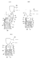
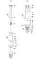
- FIG. 6 is a cross-sectional view showing a state where a surgical guide having a guide ring and a drill having an annular guide body are used to drill an implant insertion hole in a jawbone.
- (A) shows a state in which the drill is moved from the outside to the inside of the lower jaw
- (B) shows a state in which the drill is moved from above to below
- (C) shows a state in which the drill descends and stops.
- It is a top view which shows the state which attached the surgical guide with which the guide ring was mounted
- It is a top view which shows the other example of a guide ring.
- FIG. 6 is a front view showing still another type of drill “trefin bar”. It is a front view which shows the adapter for implant insertion used when inserting an implant into an insertion hole.
- (A) shows a state before the insertion adapter is attached to the implant
- (B) shows a state in which the insertion adapter is attached to the implant, partially in cross section.
- It is a front view which shows the mount for manual rotation (adapter for implant insertion) used when inserting an implant into an insertion hole.
- (A) shows a state before the mount is mounted on the implant
- (B) shows a state where the mount is mounted on the implant in a partial cross section.
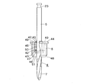
- FIG. 17 is a perspective view of a drill equipped with the ring guide body shown in FIG. 16.
- FIG. 18 is a front view showing the ring guide body with a part cut away in the drill shown in FIG. 17. It is an expanded sectional view which shows the axial part of the drill which has a permite
- FIG. 17 is a cross-sectional view showing a state where a surgical guide having the guide ring shown in FIG. 15 and a drill having a ring guide body shown in FIG.
- (A) shows a state in which the drill is moved from the outside to the inside of the lower jaw
- (B) shows a state in which the drill is moved from above to below
- (C) shows a state in which the drill descends and stops. It is a top view which shows the other example of a ring guide body.
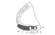
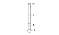
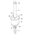
- a guide system such as an implant drill of the present invention has a guide ring 3 mounted on a support portion 2 of a surgical guide 1 as shown in FIGS. 1 and 2, and further includes a drill 4 as shown in FIGS.
- a ring guide body 6 attached to the shaft portion 5 is provided.
- a slit portion 8 into which the blade portion 7 of the drill 4 can be inserted is provided on the side surface of the guide ring 3.
- a guide ring 3 is provided at a position where the implant of the support portion 2 of the surgical guide 1 is mounted.
- the surgical guide 1 is supported by the adjacent teeth 10, and the support portion 2 covers the periphery of the guide ring 3.
- Corresponding notches 11 are provided.
- the slit surface 12 of the guide ring 3 is manufactured in parallel as shown in FIGS. 1 and 2, is manufactured at a required opening angle as shown in FIG. 9, or is on the same line as shown in FIG. It is manufactured in parallel.
- the ring guide body 6 attached to the drill 4 is adapted to be slidable by fitting into the guide ring 3.
- a tapered portion 13 is provided at the lower end portion of the ring guide body 6 so that the ring guide body 6 can be smoothly guided into the guide ring 3 when fitted.
- the tapered portion 13 may be provided also at the upper end portion of the ring guide body 6.
- the ring guide body 6 is fixed to the shaft portion 5 with a stopper 16.
- the ring guide body 6 is fixed at a predetermined position by the stopper 16 by adjusting the length of the drill blade 7 so as to be the depth of the insertion hole 17 of the implant.
- a hexagon socket head cap screw is used as the stopper 16, and the hexagon socket head cap screw is engaged with a screw hole 18 provided in the ring guide body 6. It is preferable to insert the bolt to a slightly deeper position so that the head of the bolt does not protrude from the outer surface of the ring guide body 6 during the engagement.
- drills there are various types of drills to be used, such as a spiral drill type shown in FIG. 5, a round bar type shown in FIG. 11, and a trephine bar type shown in FIG.
- a spiral drill type shown in FIG. 5 a round bar type shown in FIG. 11
- a trephine bar type shown in FIG. When a straight shaft is used as in the round bar of FIG. 11, the hole 15 of the ring guide body 6 can be omitted.
- the position of the water injection hole 20 is shifted by 45 degrees in the circumferential direction and displayed with a broken line so that the position of the water injection hole 20 can be easily understood.
- the friction portion between the drill blade 7 and the implant insertion hole 17 is cooled by water flowing through the water injection hole and along the drill blade 7.
- channel 19 and the water injection hole 20 are provided in the axial direction (axial direction of a drill) of the ring guide body 6 in an Example, it replaces with this direction, for example, an oblique direction or a helical direction. You may make it provide in.
- the gingiva 21 corresponding to the insertion hole of the implant is cut open to expose the mandible 22.
- the surgical guide 1 is mounted on the lower jaw in the state shown in FIG. In this case, the surgical guide 1 is attached to the mandible via the adjacent teeth 10, and the lower surface of the support portion 2 corresponding to the insertion hole of the implant is not in contact with the mandible 22.
- the drill is moved in the direction of the arrow X, and the blade portion 7 of the drill is moved to the position of the surgical guide 1.
- the guide part 3 is guided through the notch part 11 of the support part 2 and the slit part 8 of the guide ring 3.
- the drill 4 is lowered in the direction of arrow Y to guide the ring guide body 6 that rotates together with the drill into the guide ring 3, and the mandible 22 is held by the drill blade 7 of the drill.
- the insertion hole 17 of the implant is formed in the.
- the drill 4 is lowered, and the lower end 25 of the ring guide body 6 is brought into contact with the mandible 22. Since the insertion hole 17 is formed at a predetermined depth at this contact position, the drilling is stopped at this position. This stop position can be confirmed by looking through the slit portion 8 of the guide ring and the notch portion 11 of the surgical guide.
- the drill descends when the ring guide body 6 contacts the guide ring 3. Since this stops, this position can be used as a stop position of the drill.
- the implant insertion hole is drilled using a spiral drill.
- other drills such as the drill shown in FIG. Can be used.
- drilling is performed instead of spiral drills having various blade diameters.
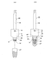
- FIG. 13 shows an implant insertion adapter 26 used when the implant 27 is inserted into the jaw hole insertion hole 17.
- a convex portion 29 having a hexagonal cross section provided at the lower end portion of the adapter 26 for insertion via a tapered portion 28 is replaced with a convex portion 29 having a hexagonal cross section and a tapered concave portion 40 provided at the upper end portion of the implant 27.
- the recess 30 is engaged.
- a rubber ring 32 is attached to the outer peripheral groove of the shaft end portion 31 provided at the lower end of the convex portion 29, and the shaft end portion 31 is inserted into the screw hole 33 of the implant to insert the implant 27.
- the adapter 26 is supported.
- FIG. 14 shows a hand-rotated implant insertion adapter 26 that is used when the implant 27 is inserted into the insertion hole 17 of the jawbone.
- the insertion adapter 26 includes a mount 35 and a support shaft 37 having a knurled knob 36.
- the support shaft 37 is inserted into the mount 35, the screw portion 38 provided at the lower end of the support shaft 37 is engaged with the screw hole 33 formed in the implant 27, and the implant 27 is attached to the insertion adapter 26.
- the convex section 29 having a hexagonal cross section provided at the lower end portion of the mount 35 via the tapered section 28 is connected to the concave section 40 having a tapered shape provided at the upper end section of the implant 27 and the concave section 30 having a hexagonal section.
- a ring guide body 6 is provided on the outer peripheral portion of the shaft portion 34 of the adapter 26 for implant insertion shown in FIGS.
- the implant 27 is inserted into the implant insertion hole 17 using the insertion adapter 26, the implant 27 is attached to the lower end portion of the insertion adapter 26, and the implant is inserted from the slit portion 8 of the guide ring 3. Then, the adapter 26 for insertion is rotated using a handpiece or the like and screwed.
- the ring guide body 6 can be provided with a stopper 16, a water injection groove 19, and a water injection hole 20 as in the case of the drill.
- the shaft portion 34 of the adapter 26 for insertion is provided with a thick shaft portion (step portion)
- the hole portion 15 is a ring guide for guiding the thick shaft portion as in the case of the drill. Provided on the body 6.
- an implant device such as an abutment holder or a hex driver is used.
- the axis of the implant device is used.
- the above parts are mounted by providing a ring guide body at the part.
- the guide ring 3 in FIG. 15 and the ring guide body 6 in FIG. 16 show other structures.
- the cross-sectional shape of the inner peripheral surface of the guide ring 3 is formed in an ellipse, and the cross-sectional shape of the outer peripheral surface of the ring guide body 6 is also formed in an ellipse correspondingly.
- the ring guide body 6 is mounted on the shaft portion 5 of the drill 4 so as to be movable in the axial direction and rotatable.
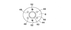
- annular groove 42 is provided in the upper and lower portions of the ring guide body 6, and an O-ring 43 made of a wear-resistant material such as nitrile rubber, silicon rubber, urethane rubber or the like is fitted into the groove. , Glued or fixed.
- the O-ring 43 reduces the frictional force of the contact surface between the shaft portion 5 of the drill 4 and the inner surface of the ring guide body 6.
- a slide bearing is provided, or the shaft portion 5 of the drill 4 and the inner surface of the ring guide body 6 can be moved directly in the axial direction without providing the O-ring 43 and the slide bearing, and You may make it fit so that rotation is possible.
- the ring guide body 6 is provided with a flange portion 44, a hole portion 45 for inserting the shaft portion 5 of the drill, a hole portion 47 for inserting the thick shaft portion 46 of the shaft portion 5 of the drill, a tapered portion 48, and a water injection hole 49. It has been.
- a protrusion 50 provided on the shaft portion 5 of the drill is inserted from the notch portion 51 formed in the O-ring 43, and this protrusion 50 is connected to the ring.
- the axial movement of the drill is restricted by being positioned in the hole 45 of the guide body 6.
- the projection 50 is attached by inserting a pin into the shaft portion 5 of the drill or by welding or bonding the projection. Note that the protrusion 50 may not be provided.
- the thick shaft portion 46 of the drill is provided integrally with the shaft portion 5 or is fixed to the shaft portion 5 with a screw or the like so that the mounting position of the thick shaft portion 46 can be adjusted.
- the implant insertion hole 17 is formed using the surgical guide 1 having the elliptical guide ring 3 and the drill 4 having the ring guide body 6 will be described with reference to FIG. Note that members that are the same as or equivalent to the members shown in FIG. First, as shown in FIG. 20A, the gingiva 21 corresponding to the insertion hole of the implant is cut open, and the mandible 22 is exposed.
- the surgical guide 1 is mounted on the lower jaw in the state shown in FIG. In this case, the surgical guide 1 is attached to the lower jaw through the adjacent teeth 10, and the lower surface of the support portion 2 corresponding to the insertion hole of the implant is not in contact with the lower jaw bone 22.
- the drill is moved in the direction of the arrow X, and the blade portion 7 of the drill is moved to the position of the surgical guide 1.
- the guide part 3 is guided through the notch part 11 of the support part 2 and the slit part 8 of the guide ring 3.
- the drill 4 is lowered in the direction of the arrow Y, the ring guide body 6 is guided into the guide ring 3, and the implant is inserted into the mandible 22 by the blade portion 7 of the drill. Hole 17 is formed.
- the drill 4 is lowered, the ring guide body 6 comes to rest with its flange portion 44 coming into contact with the guide ring 3, and then the drill 4 is lowered and drilled.
- the drill 4 is lowered, and the lower end surface 53 of the handpiece 24 is brought into contact with the upper surface of the flange portion 44 (actually, the O-ring 43) of the ring guide body. Since the insertion hole 17 is formed at a predetermined depth at this contact position, the drilling is stopped at this position. This stop position can be confirmed by looking through the slit portion 8 of the guide ring and the notch portion 11 of the surgical guide.
- the ring guide body 6 shown in FIG. 21 has a magnet 52 embedded in the upper portion of the ring guide body 6 as shown in FIG. 16, and the magnet 52 is used when the insertion hole of the implant is enlarged sequentially and the drill is replaced.
- the ring guide body 6 can be temporarily supported on the lower part of the handpiece.
- two magnets 52 are provided, but one or a plurality other than two may be provided depending on the strength of the magnet.
Abstract
Description
このサージカルガイドには、顎骨等に支持するサージカルガイドにドリルを案内するための金属製のガイドリングが嵌入されている。
このガイドリングを用いて穿孔する方法として、ガイドリングの内面に直接ドリル刃部を接触させて穿孔するものと、特許第3793603号特許公報に示されるように、ハンドピース等の穿孔器具にガイド部材を取り付け、このガイド部材を上記穿孔器具に装着されるドリルに接触しないようにドリルの周囲に位置させ、このガイド部材をガイドリングに案内して穿孔するものが知られている。
また、穿孔の際に、ガイドリングとドリルの刃部との間に摩擦熱が発生し、この摩擦熱によりガイドリングとドリルの刃部を傷めると共に、顎骨にも悪影響を及ぼすことがあった。
更に、インプラントの挿入孔を形成した後、挿入孔にインプラント挿入用アダプター等の器具を用いてインプラントを挿入する際に、これらの器具が前後左右に振れて傾いてしまうことがあった。また、アバットメントホルダーやヘックスドライバー等の器具を用いてインプラントにアバットメントやヒーリングキャップ、ヒーリングアバットメント等を装着する際にも、器具が傾いて装着作業に手間取ることがあった。
サージカルガイドにガイドリングを設ける際は、インプラントが装着される部分の顎骨をCT撮影し、この撮影によって得られる立体的画像等を用いてガイドリングの取付位置や取付方向等が決定される。
ガイドリングは、上記リングガイド体の外周面が円形の断面形状であれば、このリングガイド体がガイドリング内にその軸方向に移動可能であって回転可能に嵌合し案内されるようにガイドリングの内周面が円形の断面形状に製作される。
ただし、リングガイド体がガイドリング内で回転可能なものにする場合は、断面形状の組み合わせはこれのみに限定されるものではない。
ガイドリングは、通常、内径D1が約4mm~9mmに、外径D2が約5mm~10mmのリング形態に製作されるが、これらの寸法はこれのみに限定されるものではない。
リングガイド体の外周面が非円形(楕円形、卵形、四角形・六角形等の多角形、これらの複合形等)の断面形状であれば、ガイドリングの内周面の断面形状は、リングガイド体がガイドリング内にその軸方向に移動可能であって回転不可能に嵌合し案内されるようにリングガイド体の外周の形状に対応して非円形に製作される。
ただし、リングガイド体がガイドリング内で回転不可能なものにする場合は、断面形状の組み合わせはこれのみに限定されるものではない。
ドリル以外のもので、インプラント挿入孔アダプター、アバットメントホルダー、ヘックスドライバー、挿入孔の骨幅を増大したりするオステオトーム、ボーンスプレッダー、ボーンエキスパンダー等のインプラント用器具にもリングガイド体を装着して使用することが可能である。
インプラントを挿入する際には、インプラントに装着するインプラント挿入用アダプターとして、ハンドピースを用いて挿入するタイプ(図13)のものと、手指を用いて挿入するタイプ(図14)のものを用いることができる。
その他、顎骨の吸収が著しい場合などでは、深い位置での顎骨穿孔やインプラント挿入の際に用いるドリルエクステンション、エキステンションホルダー等のインプラント用器具にリングガイド体を装着して使用することが可能である。
一般的にはドリルの刃部の径がインプラントの径に合わせて約2mm~5mmほどに製作されているので、スリット部の幅W(図2、図9、図10)は、これに合わせてインプラントの最大径より少し大きな径である通常4mm~6mm程度に製作されている。なお、このスリット部の幅Wは、上記寸法のみに限定されるものではない。
また、スリット部の面は、スリット面どうしが平行になるように製作したり(図1、図2)、同一線上になるように製作したり(図10)、適宜の開角度(図9に示すものでは角度120度)をもって斜状になるように製作したりすることができる。
このようにリングガイド体を止め具で固定すると、リングガイド体の位置を移動させてドリルの刃部が挿入される長さを調整することができ、これによってインプラントの長さに応じた所定の深さに穿孔することができる。
上記止め具としては、六角穴付きボルトや止めねじその他のものを用いることができるが、いずれの場合でも、リングガイド体をガイドリング内に円滑に案内できるように、止め具の頭部がリングガイド体の外周面より突出しないようにしておくのがよい。
リングガイド体は、ドリル等の軸部に軸方向に移動可能に設けたり、ドリル等の軸部に対して回転可能(リングガイド体とドリル等の軸部の断面形状を円形に形成)または回転不可能(リングガイド体とドリル等の軸部の断面形状を非円形に形成)に設けたり、両部材間をねじ係合にしたりすることができる。両部材間をねじ係合にした場合は、ダブルナット等を用いてリングガイド体を所定の位置で固定するようにしてもよい。
なお、上記リングガイド体は、ドリルの刃部を案内するための孔部を省略することができ、またこのリングガイド体をドリルの軸部に一体的に設けることができる。
なお、リングガイド体は、各種の金属や硬質のプラスチック材等の丈夫な材料で製作することができ、材料としては耐磨耗性があって、人体に悪影響を及ぼさないものが好ましい。
また、アバットメントやヒーリングキャップやヒーリングアバット等のパーツをインプラントに装着する場合には、アバットメントホルダーやヘックスドライバー等のインプラント用器具が用いられる。この場合も器具の軸部の外周部には上記のリングガイド体が設けられる。
更に、リングガイド体に注水孔や注水溝を設けているので、この注水孔や注水溝より注水される冷却水によってリングガイド体とガイドリングとの接触面やドリルの刃部またはインプラントと顎骨との接触面に生ずる摩擦熱を冷却することができ、またこの冷却によって顎骨に悪影響を及ぼすこともないし、摩擦接触によって発生する粉塵等を冷却水で洗い流すこともできる。
本発明のインプラント用ドリル等のガイドシステムは、図1及び図2に示すようなサージカルガイド1の支持部2に装着したガイドリング3を有し、更に図4~図6に示すようなドリル4の軸部5に装着したリングガイド体6を備えている。このガイドリング3の側面には、ドリル4の刃部7が挿入可能なスリット部8が設けられている。
なお、実施例では、止め具16として六角穴付きボルトを用いており、この六角穴付きボルトをリングガイド体6に設けたねじ孔18に係合させている。係合の際に、ボルトの頭部がリングガイド体6の外表面より出ないようにボルトを少し奥の位置まで挿入するのが好ましい。
また、穿孔時に、ドリルの刃部7とインプラントの挿入孔17の接触面にも摩擦熱が発生するので、リングガイド体6の中心部側にその軸部方向に沿って注水孔20(図6では、注水孔20の位置が理解し易いように、その位置を周方向に45度ずらし破線をもって表示している)を設けている。この注水孔を通りドリルの刃部7に沿って流れる水によって、ドリルの刃部7とインプラントの挿入孔17の摩擦部を冷却している。
なお、上記注水溝19及び注水孔20は、実施例では、リングガイド体6の軸方向(ドリルの軸方向)に設けられているが、この方向に代えて、例えば斜状方向や螺旋状方向に設けるようにしてもよい。
先ず、図7(A)に示すように、インプラントの挿入孔に相当する部分の歯肉21を切り開き、下顎骨22を露出させる。下顎に図8に示すような状態でサージカルガイド1を装着する。この場合、サージカルガイド1は隣接する歯10を介して下顎に装着され、インプラントの挿入孔に相当する部分の支持部2の下面は、下顎骨22に接しない状態になっている。
この状態で、ドリル4の軸部5の上部(取付部23)をチャックしたハンドピース(穿孔装置)24を用い、そのドリルを矢印X方向に移動させ、ドリルの刃部7をサージカルガイド1の支持部2の切り欠き部11及びガイドリング3のスリット部8に通してガイドリング3内に案内する。
この例では、図17~図19に示すように、リングガイド体6がドリル4の軸部5に軸方向に移動可能、かつ回転可能に装着されている。この場合、リングガイド体6の上部及び下部に環状溝42を設け、この溝に、ニトリルゴム、シリコンゴム、ウレタンゴム等の耐摩耗性の材料で製作されたOリング43が、嵌合されたり、接着されたりして固定されている。このOリング43によって、ドリル4の軸部5とリングガイド体6の内面の接触面の摩擦力が軽減される。なお、このOリングに代えて、すべり軸受を設け、或いはこれらのOリング43やすべり軸受を設けないでドリル4の軸部5とリングガイド体6の内面とを直接軸方向に移動可能、かつ回転可能に嵌合させてもよい。
先ず、図20(A)に示すように、インプラントの挿入孔に相当する部分の歯肉21を切り開き、下顎骨22を露出させる。下顎に図8に示すような状態でサージカルガイド1を装着する。この場合、サージカルガイド1は隣接する歯10を介して下顎に装着され、インプラントの挿入孔に相当する部分の支持部2の下面は下顎骨22に接しない状態になっている。
この状態で、ドリル4の軸部5の上部(取付部23)をチャックしたハンドピース(穿孔装置)24を用い、そのドリルを矢印X方向に移動させ、ドリルの刃部7をサージカルガイド1の支持部2の切り欠き部11及びガイドリング3のスリット部8に通してガイドリング3内に案内する。
2 支持部
3 ガイドリング
4 ドリル
6 リングガイド体
7 刃部
8 スリット部
14、15 孔部
16 止め具
19 注水溝
20、49 注水孔
24 ハンドピース
26 インプラント挿入用アダプター
27 インプラント
43 Oリング
44 フランジ部
46 太軸部
52 磁石
Claims (14)
- ガイドリングを有するサージカルガイドと、インプラント用ドリルやインプラント挿入用アダプター等のインプラント用器具を備え、このインプラント用器具の軸部に、上記ガイドリング内に案内するリングガイド体を設けたインプラント用器具のガイドシステム。
- ガイドリングの側面に、インプラント用ドリルの刃部やインプラントを側方より挿入可能な幅を有し、かつガイドリングの内径より小さい幅を有するスリット部を設けた請求項1に記載のインプラント用器具のガイドシステム。
- リングガイド体の上部に磁石を設けた請求項1または2に記載のインプラント用器具のガイドシステム。
- リングガイド体に注水孔、または注水孔と注水溝を設けた請求項1ないし3のいずれかに記載のインプラント用器具のガイドシステム。
- リングガイド体をインプラント用器具の軸部の所定の位置に固定する止め具を設けた請求項1ないし4のいずれかに記載のインプラント用器具のガイドシステム。
- リングガイド体がインプラント用器具の軸部に軸方向に移動可能に支持されると共にそのインプラント用器具の軸部に対し回転可能に形成され、かつリングガイド体がガイドリングに対し回転可能に形成された請求項1ないし4のいずれかに記載のインプラント用器具のガイドシステム。
- リングガイド体がインプラント用器具の軸部に軸方向に移動可能に支持されると共にそのインプラント用器具の軸部に対し回転不可能に形成され、かつリングガイド体がガイドリングに対し回転可能に形成された請求項1ないし5のいずれかに記載のインプラント用器具のガイドシステム。
- リングガイド体がインプラント用器具の軸部に軸方向に移動可能に支持されると共にそのインプラント用器具の軸部に対し回転可能に形成され、かつリングガイド体がガイドリングに対し回転不可能に形成された請求項1ないし4のいずれかに記載のインプラント用器具のガイドシステム。
- インプラント用ドリルやインプラント挿入用アダプター等のインプラント用器具の軸部に、サージカルガイドのガイドリング内に案内されるリングガイド体を設けたインプラント用器具。
- リングガイド体の上部に磁石を設けた請求項9に記載のインプラント用器具。
- リングガイド体に注水孔、または注水孔と注水溝を設けた請求項9または10に記載のインプラント用器具。
- リングガイド体をインプラント用器具の軸部の所定の位置に固定する止め具を設けた請求項9ないし11のいずれかに記載のインプラント用器具。
- リングガイド体がインプラント用器具の軸部に軸方向に移動可能に支持されると共にそのインプラント用器具の軸部に対し回転可能に形成された請求項9ないし11のいずれかに記載のインプラント用器具。
- リングガイド体がインプラント用器具の軸部に軸方向に移動可能に支持されると共にそのインプラント用器具の軸部に対し回転不可能に形成された請求項9ないし12のいずれかに記載のインプラント用器具。
Priority Applications (2)
| Application Number | Priority Date | Filing Date | Title |
|---|---|---|---|
| US13/261,141 US20120109140A1 (en) | 2009-09-01 | 2010-08-25 | Implant Instrument and Guide System for the Implant Instrument |
| JP2011505290A JP4852183B2 (ja) | 2009-09-01 | 2010-08-25 | インプラント用器具及びインプラント用器具のガイドシステム |
Applications Claiming Priority (2)
| Application Number | Priority Date | Filing Date | Title |
|---|---|---|---|
| JP2009-201263 | 2009-09-01 | ||
| JP2009201263 | 2009-09-01 |
Publications (1)
| Publication Number | Publication Date |
|---|---|
| WO2011027689A1 true WO2011027689A1 (ja) | 2011-03-10 |
Family
ID=43649228
Family Applications (1)
| Application Number | Title | Priority Date | Filing Date |
|---|---|---|---|
| PCT/JP2010/064345 WO2011027689A1 (ja) | 2009-09-01 | 2010-08-25 | インプラント用器具及びインプラント用器具のガイドシステム |
Country Status (3)
| Country | Link |
|---|---|
| US (1) | US20120109140A1 (ja) |
| JP (1) | JP4852183B2 (ja) |
| WO (1) | WO2011027689A1 (ja) |
Cited By (13)
| Publication number | Priority date | Publication date | Assignee | Title |
|---|---|---|---|---|
| JP2013009948A (ja) * | 2011-06-01 | 2013-01-17 | Kinki Univ | 歯科インプラント用治具及びそのセット並びにドリル用バー及びそのセット |
| WO2013169858A1 (en) | 2012-05-08 | 2013-11-14 | The Broad Institute, Inc. | Diagnostic and treatment methods in patients having or at risk of developing resistance to cancer therapy |
| JP2014168553A (ja) * | 2013-03-02 | 2014-09-18 | Implantdent Co Ltd | 歯科用インプラント埋設穴形成補助装置及びシステム |
| KR101545973B1 (ko) * | 2015-01-30 | 2015-08-21 | 주식회사 덴티스 | 임플란트 시술용 드릴 가이드휠 |
| JP2016026559A (ja) * | 2014-07-07 | 2016-02-18 | 株式会社インプラントデント | インプラント用骨平面形成具 |
| JP2016055190A (ja) * | 2012-10-22 | 2016-04-21 | 医療法人社団アイ・ティー | アバットメント、フィクスチャー、歯科インプラント用セット、歯科タップ、歯科ガイド、歯科タップセット、および歯科ドリル |
| TWI573568B (zh) * | 2015-08-17 | 2017-03-11 | Hsieh-Hsing Lin | Dental use of replaceable bone drilling and positioning device |
| CN108371562A (zh) * | 2018-02-12 | 2018-08-07 | 佛山科学技术学院 | 一种牙科种植导板 |
| WO2019194593A3 (ko) * | 2018-04-04 | 2019-12-05 | Lee Taekyoung | 치과 임플란트 수술용 드릴 비트 |
| KR102058681B1 (ko) * | 2017-08-29 | 2019-12-23 | 김정환 | 깊이 조절이 가능한 임플란트용 드릴 어셈블리 |
| KR102082212B1 (ko) * | 2019-10-28 | 2020-02-26 | 주식회사 덴탈스튜디오 | 치과용 드릴 조립체 |
| WO2022131233A1 (ja) * | 2020-12-14 | 2022-06-23 | ニプロ株式会社 | 医療用シャフト組立体および医療用のシャフトドリル |
| WO2023282398A1 (ko) * | 2021-07-05 | 2023-01-12 | (주)메디메카 | 치아 임플란트 시술용 식립 가이드 장치 |
Families Citing this family (11)
| Publication number | Priority date | Publication date | Assignee | Title |
|---|---|---|---|---|
| US9687322B2 (en) * | 2012-09-28 | 2017-06-27 | Robert P. Carmichael | Dental implant positioning system |
| US9452034B1 (en) * | 2012-10-23 | 2016-09-27 | Javier Urquiola | Hybrid passively fitting prosthodontic frameworks |
| CH708017A1 (de) * | 2013-04-16 | 2014-10-31 | Dominik Meier | Bearbeitungssystem für orale Implantologie. |
| EP3038559B1 (en) * | 2013-08-26 | 2018-10-10 | Elos Medtech Timmersdala AB | Dental drill system |
| WO2015030653A1 (en) | 2013-08-26 | 2015-03-05 | Elos Medtech Timmersdala Ab | Dental surgery device |
| ES2841824T3 (es) * | 2014-09-02 | 2021-07-09 | Bortolo Giuliano Maino | Plantilla quirúrgica para implantes palatales |
| JP2016154856A (ja) * | 2015-02-25 | 2016-09-01 | 株式会社DentalBank | 歯科用治具、除去穴充填用人工骨、トレフィンバーおよび歯科用治具の製造方法 |
| AU2016263600A1 (en) * | 2015-05-21 | 2017-12-07 | Huwais IP Holding LLC | Axial stop gauge and jig guide for surgical drill |
| KR102225465B1 (ko) * | 2019-01-22 | 2021-03-10 | 주식회사 한마음 | 치과 임플란트의 픽스츄어 추출 보조기구 |
| CN110226979B (zh) * | 2019-05-30 | 2024-04-02 | 杭州六维齿科医疗技术有限公司 | 一种带有自导航钻套的种植备孔钻系统 |
| KR102566293B1 (ko) * | 2020-09-28 | 2023-08-18 | 서울대학교산학협력단 | 구강경유 수술을 위한 보호 장치 |
Citations (8)
| Publication number | Priority date | Publication date | Assignee | Title |
|---|---|---|---|---|
| JPH09294750A (ja) * | 1996-05-02 | 1997-11-18 | Morihiro Hattori | 骨穿孔装置 |
| JP2000513985A (ja) * | 1997-04-25 | 2000-10-24 | ズルツァー オルソペディー アクチェンゲゼルシャフト | 軟骨内または骨軟骨孔の生成装置 |
| JP2001212158A (ja) * | 2000-02-07 | 2001-08-07 | Keiji Koyanagi | インプラント窩形成用ガイドと形成装置及び形成方法 |
| JP2005518834A (ja) * | 2002-02-28 | 2005-06-30 | マテリアライズ・ナムローゼ・フエンノートシャップ | 歯科インプラントを配置するための方法および装置 |
| JP2007512079A (ja) * | 2003-12-03 | 2007-05-17 | キム、ジョンピル | インプラント用のステント補助具 |
| JP3149000U (ja) * | 2006-01-12 | 2009-03-12 | マテリアライズ・デンタル・ナムローゼ・フエンノートシャップMaterialise Dental N.V. | 歯科用穿孔アセンブリ |
| JP2009165799A (ja) * | 2007-09-12 | 2009-07-30 | Imagunooshisu Kk | インプラント植立用穿孔器具、ハンドピース、ハンドピース用アダプタおよびサージカルガイド |
| JP2010119465A (ja) * | 2008-11-17 | 2010-06-03 | Wakayoshi Seisakusho Co Ltd | 医療用切削具の案内具 |
Family Cites Families (12)
| Publication number | Priority date | Publication date | Assignee | Title |
|---|---|---|---|---|
| JPS6459113A (en) * | 1987-08-31 | 1989-03-06 | Komatsu Mfg Co Ltd | Measurement of deflection for road surface |
| EP1189547B8 (fr) * | 1999-06-03 | 2009-06-03 | Arsline S.A. | Dispositif de securite comportant une butee pour outil de forage utilisable notamment en chirurgie dentaire et dispositif de precalibrage et de memorisation de la profondeur de forage |
| US20090176187A1 (en) * | 2006-01-06 | 2009-07-09 | Alessio Esposti | Dental Handpiece |
| CN101415376B (zh) * | 2006-03-30 | 2013-09-18 | 登特斯普利植入物制造有限责任公司 | 用于插入植入体的装置 |
| ITBS20060169A1 (it) * | 2006-08-02 | 2008-02-03 | Physioplant Srl | Sistema per una chirurgia implantare dentale guidata |
| US7845943B2 (en) * | 2006-09-07 | 2010-12-07 | Meitner Sean W | Method for making and using a template for locating a dental implant and components relating thereto |
| FR2910804B1 (fr) * | 2007-01-02 | 2010-03-12 | Michel Isidori | Dispositif de guidage et de modelage osseux pour la preparation de sites osseux en chirurgie |
| JP5092094B2 (ja) * | 2007-01-26 | 2012-12-05 | デンツプライ インプランツ マニュファクチュアリング ゲーエムベーハー | インプラント挿入を準備または実行する器具を備える装置 |
| US20080220390A1 (en) * | 2007-03-07 | 2008-09-11 | Michael Klein | Dental tool guide assembly |
| KR20100021954A (ko) * | 2007-06-01 | 2010-02-26 | 가부시끼가이샤 와까요시 세이사꾸쇼 | 의료용 절삭구 및 그 가이드 부재 및 절제골 채취구 |
| EP2196162B1 (en) * | 2008-12-15 | 2016-10-12 | Straumann Holding AG | Drill guide |
| US8899984B2 (en) * | 2009-05-20 | 2014-12-02 | Daniel R. Llop | CT-based, side-loading surgical and laboratory dental implant guide system and method |
-
2010
- 2010-08-25 WO PCT/JP2010/064345 patent/WO2011027689A1/ja active Application Filing
- 2010-08-25 JP JP2011505290A patent/JP4852183B2/ja not_active Expired - Fee Related
- 2010-08-25 US US13/261,141 patent/US20120109140A1/en not_active Abandoned
Patent Citations (8)
| Publication number | Priority date | Publication date | Assignee | Title |
|---|---|---|---|---|
| JPH09294750A (ja) * | 1996-05-02 | 1997-11-18 | Morihiro Hattori | 骨穿孔装置 |
| JP2000513985A (ja) * | 1997-04-25 | 2000-10-24 | ズルツァー オルソペディー アクチェンゲゼルシャフト | 軟骨内または骨軟骨孔の生成装置 |
| JP2001212158A (ja) * | 2000-02-07 | 2001-08-07 | Keiji Koyanagi | インプラント窩形成用ガイドと形成装置及び形成方法 |
| JP2005518834A (ja) * | 2002-02-28 | 2005-06-30 | マテリアライズ・ナムローゼ・フエンノートシャップ | 歯科インプラントを配置するための方法および装置 |
| JP2007512079A (ja) * | 2003-12-03 | 2007-05-17 | キム、ジョンピル | インプラント用のステント補助具 |
| JP3149000U (ja) * | 2006-01-12 | 2009-03-12 | マテリアライズ・デンタル・ナムローゼ・フエンノートシャップMaterialise Dental N.V. | 歯科用穿孔アセンブリ |
| JP2009165799A (ja) * | 2007-09-12 | 2009-07-30 | Imagunooshisu Kk | インプラント植立用穿孔器具、ハンドピース、ハンドピース用アダプタおよびサージカルガイド |
| JP2010119465A (ja) * | 2008-11-17 | 2010-06-03 | Wakayoshi Seisakusho Co Ltd | 医療用切削具の案内具 |
Cited By (17)
| Publication number | Priority date | Publication date | Assignee | Title |
|---|---|---|---|---|
| EP2716255A1 (en) * | 2011-06-01 | 2014-04-09 | Eintellex Co., Ltd. | Dental implant jig, set thereof, drilling bar, and set thereof |
| EP2716255A4 (en) * | 2011-06-01 | 2014-12-03 | Eintellex Co Ltd | DENTAL IMPLANT DEVICE, SET THEREFORE, DRILLING ROD AND SET THEREOF |
| JP2013009948A (ja) * | 2011-06-01 | 2013-01-17 | Kinki Univ | 歯科インプラント用治具及びそのセット並びにドリル用バー及びそのセット |
| WO2013169858A1 (en) | 2012-05-08 | 2013-11-14 | The Broad Institute, Inc. | Diagnostic and treatment methods in patients having or at risk of developing resistance to cancer therapy |
| US9700389B2 (en) | 2012-10-22 | 2017-07-11 | Medical Corporation It | Abutment, fixture, dental implant set, dental tap, dental guide, dental tap set and dental drill |
| JP2016055190A (ja) * | 2012-10-22 | 2016-04-21 | 医療法人社団アイ・ティー | アバットメント、フィクスチャー、歯科インプラント用セット、歯科タップ、歯科ガイド、歯科タップセット、および歯科ドリル |
| JP2014168553A (ja) * | 2013-03-02 | 2014-09-18 | Implantdent Co Ltd | 歯科用インプラント埋設穴形成補助装置及びシステム |
| JP2016026559A (ja) * | 2014-07-07 | 2016-02-18 | 株式会社インプラントデント | インプラント用骨平面形成具 |
| KR101545973B1 (ko) * | 2015-01-30 | 2015-08-21 | 주식회사 덴티스 | 임플란트 시술용 드릴 가이드휠 |
| TWI573568B (zh) * | 2015-08-17 | 2017-03-11 | Hsieh-Hsing Lin | Dental use of replaceable bone drilling and positioning device |
| KR102058681B1 (ko) * | 2017-08-29 | 2019-12-23 | 김정환 | 깊이 조절이 가능한 임플란트용 드릴 어셈블리 |
| CN108371562A (zh) * | 2018-02-12 | 2018-08-07 | 佛山科学技术学院 | 一种牙科种植导板 |
| CN108371562B (zh) * | 2018-02-12 | 2023-08-08 | 佛山科学技术学院 | 一种牙科种植导板 |
| WO2019194593A3 (ko) * | 2018-04-04 | 2019-12-05 | Lee Taekyoung | 치과 임플란트 수술용 드릴 비트 |
| KR102082212B1 (ko) * | 2019-10-28 | 2020-02-26 | 주식회사 덴탈스튜디오 | 치과용 드릴 조립체 |
| WO2022131233A1 (ja) * | 2020-12-14 | 2022-06-23 | ニプロ株式会社 | 医療用シャフト組立体および医療用のシャフトドリル |
| WO2023282398A1 (ko) * | 2021-07-05 | 2023-01-12 | (주)메디메카 | 치아 임플란트 시술용 식립 가이드 장치 |
Also Published As
| Publication number | Publication date |
|---|---|
| US20120109140A1 (en) | 2012-05-03 |
| JPWO2011027689A1 (ja) | 2013-02-04 |
| JP4852183B2 (ja) | 2012-01-11 |
Similar Documents
| Publication | Publication Date | Title |
|---|---|---|
| JP4852183B2 (ja) | インプラント用器具及びインプラント用器具のガイドシステム | |
| US8480682B2 (en) | Device for limiting the drilling depth of a drill | |
| JP3149000U (ja) | 歯科用穿孔アセンブリ | |
| EP2189130A1 (en) | Implant erecting drill tool, hand-piece, adapter for the hand-piece, and surgical guide | |
| BRPI0607102A2 (pt) | processo de fabricação de uma prótese dentária, e, aparelhagem destinada à implantação de prótese dentária | |
| BRPI0815672B1 (pt) | Guia de broca tendo um batente limitador e conjunto | |
| KR101501236B1 (ko) | 치과 임플란트용 드릴의 가이드 장치 | |
| JP4942120B2 (ja) | 医療用切削具の案内具 | |
| JP2012010758A (ja) | 穿孔ドリル及び穿孔ドリルシステム | |
| KR20160130242A (ko) | 단차 가이드를 포함하는 치과 임플란트 수술용 드릴링 도구 | |
| JP2013066665A (ja) | ストッパー及びストッパーセット | |
| WO2012165093A1 (ja) | 歯科インプラント用治具及びそのセット並びにドリル用バー及びそのセット | |
| JP5493171B2 (ja) | 外科用テンプレート位置決装置 | |
| CA2484475A1 (en) | Adjustable dental implant drill guide apparatus | |
| TW201511739A (zh) | 植入物用植入器及植入物 | |
| JP5855378B2 (ja) | 歯科用穿孔ドリルキット | |
| AU8995101A (en) | Dental implant-carrier assembly | |
| JP4524448B2 (ja) | 医療用回転切削器具のアタッチメント | |
| WO2009035359A1 (en) | Precision device for dental implant placement | |
| JP2009207688A (ja) | インプラント植立用穿孔器具およびインプラント用ハンドピース | |
| GB2578426A (en) | Dental surgery apparatus | |
| US20190223989A1 (en) | Surgical hand drill | |
| JP6989883B1 (ja) | ドリル補助装置、スクリューガイド装置および歯科矯正器具の取り付け補助装置セット | |
| TWI834836B (zh) | 用於安裝基牙之工具總成 | |
| ES1069431U (es) | Dispositivo de taladro dental. |
Legal Events
| Date | Code | Title | Description |
|---|---|---|---|
| WWE | Wipo information: entry into national phase |
Ref document number: 2011505290 Country of ref document: JP |
|
| 121 | Ep: the epo has been informed by wipo that ep was designated in this application |
Ref document number: 10813638 Country of ref document: EP Kind code of ref document: A1 |
|
| WWE | Wipo information: entry into national phase |
Ref document number: 13261141 Country of ref document: US |
|
| NENP | Non-entry into the national phase |
Ref country code: DE |
|
| 122 | Ep: pct application non-entry in european phase |
Ref document number: 10813638 Country of ref document: EP Kind code of ref document: A1 |