EP2120772B1 - Knochenmodellierung und führungsvorrichtung zur vorbereitung von knochenstellen zur implantatsoperation - Google Patents
Knochenmodellierung und führungsvorrichtung zur vorbereitung von knochenstellen zur implantatsoperation Download PDFInfo
- Publication number
- EP2120772B1 EP2120772B1 EP07872027.3A EP07872027A EP2120772B1 EP 2120772 B1 EP2120772 B1 EP 2120772B1 EP 07872027 A EP07872027 A EP 07872027A EP 2120772 B1 EP2120772 B1 EP 2120772B1
- Authority
- EP
- European Patent Office
- Prior art keywords
- ring
- bone
- cylindrical body
- area
- seat
- Prior art date
- Legal status (The legal status is an assumption and is not a legal conclusion. Google has not performed a legal analysis and makes no representation as to the accuracy of the status listed.)
- Not-in-force
Links
- 210000000988 bone and bone Anatomy 0.000 title claims description 32
- 239000007943 implant Substances 0.000 title description 28
- 238000001356 surgical procedure Methods 0.000 title description 21
- 238000005553 drilling Methods 0.000 claims description 14
- 238000002360 preparation method Methods 0.000 claims description 14
- 210000001519 tissue Anatomy 0.000 claims description 9
- RTAQQCXQSZGOHL-UHFFFAOYSA-N Titanium Chemical compound [Ti] RTAQQCXQSZGOHL-UHFFFAOYSA-N 0.000 claims description 4
- MCMNRKCIXSYSNV-UHFFFAOYSA-N Zirconium dioxide Chemical compound O=[Zr]=O MCMNRKCIXSYSNV-UHFFFAOYSA-N 0.000 claims description 4
- 230000000295 complement effect Effects 0.000 claims description 4
- 229910000811 surgical stainless steel Inorganic materials 0.000 claims description 3
- 239000010936 titanium Substances 0.000 claims description 3
- 229910052719 titanium Inorganic materials 0.000 claims description 3
- 229910001069 Ti alloy Inorganic materials 0.000 claims description 2
- 239000000919 ceramic Substances 0.000 claims description 2
- 230000002093 peripheral effect Effects 0.000 claims description 2
- 210000004072 lung Anatomy 0.000 claims 1
- 238000000034 method Methods 0.000 description 14
- 239000006185 dispersion Substances 0.000 description 5
- 210000004195 gingiva Anatomy 0.000 description 4
- 210000004877 mucosa Anatomy 0.000 description 4
- 208000010392 Bone Fractures Diseases 0.000 description 3
- 206010017076 Fracture Diseases 0.000 description 3
- 238000002324 minimally invasive surgery Methods 0.000 description 3
- 235000012830 plain croissants Nutrition 0.000 description 3
- 238000009933 burial Methods 0.000 description 2
- 238000013461 design Methods 0.000 description 2
- 238000000605 extraction Methods 0.000 description 2
- 230000035515 penetration Effects 0.000 description 2
- 238000012546 transfer Methods 0.000 description 2
- 208000035965 Postoperative Complications Diseases 0.000 description 1
- 210000003484 anatomy Anatomy 0.000 description 1
- 230000000903 blocking effect Effects 0.000 description 1
- 230000006378 damage Effects 0.000 description 1
- 230000002950 deficient Effects 0.000 description 1
- 230000000593 degrading effect Effects 0.000 description 1
- 239000004053 dental implant Substances 0.000 description 1
- 230000006866 deterioration Effects 0.000 description 1
- 238000011161 development Methods 0.000 description 1
- 238000002059 diagnostic imaging Methods 0.000 description 1
- 239000004459 forage Substances 0.000 description 1
- 239000012634 fragment Substances 0.000 description 1
- 230000035876 healing Effects 0.000 description 1
- 238000003780 insertion Methods 0.000 description 1
- 230000037431 insertion Effects 0.000 description 1
- 210000004373 mandible Anatomy 0.000 description 1
- 239000000463 material Substances 0.000 description 1
- 210000002050 maxilla Anatomy 0.000 description 1
- 229910052751 metal Inorganic materials 0.000 description 1
- 239000002184 metal Substances 0.000 description 1
- 239000011347 resin Substances 0.000 description 1
- 229920005989 resin Polymers 0.000 description 1
- 230000000451 tissue damage Effects 0.000 description 1
- 231100000827 tissue damage Toxicity 0.000 description 1
- 230000008354 tissue degradation Effects 0.000 description 1
- 230000000007 visual effect Effects 0.000 description 1
Images

Classifications
-
- A—HUMAN NECESSITIES
- A61—MEDICAL OR VETERINARY SCIENCE; HYGIENE
- A61B—DIAGNOSIS; SURGERY; IDENTIFICATION
- A61B17/00—Surgical instruments, devices or methods
- A61B17/16—Instruments for performing osteoclasis; Drills or chisels for bones; Trepans
- A61B17/17—Guides or aligning means for drills, mills, pins or wires
- A61B17/1739—Guides or aligning means for drills, mills, pins or wires specially adapted for particular parts of the body
- A61B17/176—Guides or aligning means for drills, mills, pins or wires specially adapted for particular parts of the body for the jaw
-
- A—HUMAN NECESSITIES
- A61—MEDICAL OR VETERINARY SCIENCE; HYGIENE
- A61C—DENTISTRY; APPARATUS OR METHODS FOR ORAL OR DENTAL HYGIENE
- A61C1/00—Dental machines for boring or cutting ; General features of dental machines or apparatus, e.g. hand-piece design
- A61C1/08—Machine parts specially adapted for dentistry
- A61C1/082—Positioning or guiding, e.g. of drills
- A61C1/084—Positioning or guiding, e.g. of drills of implanting tools
-
- A—HUMAN NECESSITIES
- A61—MEDICAL OR VETERINARY SCIENCE; HYGIENE
- A61B—DIAGNOSIS; SURGERY; IDENTIFICATION
- A61B17/00—Surgical instruments, devices or methods
- A61B17/16—Instruments for performing osteoclasis; Drills or chisels for bones; Trepans
- A61B17/1604—Chisels; Rongeurs; Punches; Stamps
-
- A—HUMAN NECESSITIES
- A61—MEDICAL OR VETERINARY SCIENCE; HYGIENE
- A61B—DIAGNOSIS; SURGERY; IDENTIFICATION
- A61B17/00—Surgical instruments, devices or methods
- A61B17/16—Instruments for performing osteoclasis; Drills or chisels for bones; Trepans
- A61B17/1662—Instruments for performing osteoclasis; Drills or chisels for bones; Trepans for particular parts of the body
- A61B17/1673—Instruments for performing osteoclasis; Drills or chisels for bones; Trepans for particular parts of the body for the jaw
-
- A—HUMAN NECESSITIES
- A61—MEDICAL OR VETERINARY SCIENCE; HYGIENE
- A61B—DIAGNOSIS; SURGERY; IDENTIFICATION
- A61B90/00—Instruments, implements or accessories specially adapted for surgery or diagnosis and not covered by any of the groups A61B1/00 - A61B50/00, e.g. for luxation treatment or for protecting wound edges
- A61B90/03—Automatic limiting or abutting means, e.g. for safety
- A61B2090/033—Abutting means, stops, e.g. abutting on tissue or skin
- A61B2090/036—Abutting means, stops, e.g. abutting on tissue or skin abutting on tissue or skin
Definitions
- the originality of this invention lies in the design of the guiding device in order to perform minimally invasive surgeries by not degrading the tissues operated, by controlling the depression of the device. according to the invention, thus providing even more safety in the drilling depth and more precision in surgical procedures.
- the present inventions relate to a universal axial drill guide device for use in the preparation of bone sites in general or dental surgery in order to reduce the angular dispersion, to control the depth of drilling and respect the tissues, this device can always work with the cutting tools (drills, drill bits) described in the patent application FR 2,882,250 .
- the guiding device proposed in the patent FR 2,882,250 has made it possible to remedy axis deviation problems. It is in the form of a cylinder which is embedded in the surgical guides with an axial guide of the drill, forcing the latter to move only along the axis of the bore.
- the drill can axially carry the guide device to the gum, and sometimes even to the bone rim, causing deterioration of the gum. In addition, it is free in rotation, sometimes causing the fracture of the surgical guide.
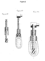
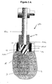
- the figure 2 (2A - 2B - 2C) represents the schematization of the use of the guide device described in the patent FR 2,882,250 in association with new drills to develop according to the invention.
- the proposed guiding device allows work in the axis of the drill but does not lock in the vertical direction and can be sinking, causing tissue damage by the rotation of the guide device.
- the depth of the drilling is ensured only by the visual control, without security.
- FR 2878 429 discloses a drilling device for insertion of a dental implant having a gripping arm.
- the present invention aims to remedy the shortcomings of the prior art.
- the device for guiding and modeling bone is remarkable in that it comprises a one-piece cylindrical body arranged and defined by two adjacent cylindrical and concentric spans, one outside and the other interior, and in that the outer cylindrical surface being established with at least two indexing means fitting in complementary shapes formed on a ring integral with a surgical guide, and in that the inner surface allows the passage and the guiding the axis of the drilling tool, and in that the lower end of the outer cylindrical bearing surface is beveled, and in that the means ensure the locking of the guiding device in depth and in rotation during the positioning of the body in the ring embedded in the surgical guide.
- the guide and modeling device referenced as a whole by (UG) comprises a cylindrical body (10) monoblock arranged and defined by two cylindrical bearing surfaces (10a-10b) adjacent and concentric, the outer one ( 10a), the other inner (10b). These two cylindrical spans are of different height or equal. These two litters are of different inside diameter.
- the outer cylindrical bearing surface (10a) is established with at least two indexing means (11 - 12) which can be lugs, slides or external cleats, diametrically opposed when there are two, and embedding in an equivalent number of complementary shapes (13a) of the groove or notch or peripheral groove type formed on a metal ring (13) integral with a surgical guide (14) thus blocking the guiding device both in rotation and in depth.
- the lower end of the outer cylindrical bearing surface (10a1) is tapered.
- the inner cylindrical bearing is established to allow the passage and guiding of the axis (15a) of the tool receiving the tool (15) itself constituting the drill.
- the cylindrical surface (10a) defines two zones (Z1 - Z2) successive in height defined as follows.
- the zone (Z1) is the free part leaving the body after its positioning on the ring (13).
- Zone (Z2) is the inner part in the ring after positioning the body in the ring.
- the zone (Z2) is of constant height of the order of 5 mm.
- the zone (Z1) is of variable height of the order of 3 to 20 mm to control the drilling depth and / or preparation of the gingiva.
- This medical device may be surgical steel, titanium or titanium alloy, P.I.C. or POM (PolyOxymethacrylate), ceramic or zirconia and their oxides, or any other material usable in biological and / or medical fields.
- P.I.C. or POM PolyOxymethacrylate
- ceramic or zirconia and their oxides or any other material usable in biological and / or medical fields.
- this guide device (UG) associated with its ring (13) can be used with any conventional surgical guide (14) perforated or by directly inserting the guide device (UG) in the pierced guide having at least two notches diametrically opposed two by two.
- the control of the depth of drilling is done by the height of this zone Z1: it can vary from 3.0mm to 15mm.
- the maximum diameter of the internal cylindrical bearing surface (10b) of 4.60mm allows the use of all necessary drill diameters or tools during surgical implant placement, the depth of this bore is at least 5mm and can vary according to the height of the working part of the universal drill that is to say from 5mm to 10mm.
- the device according to the invention is intended for the guidance of any tool used for the preparation of bone site in surgery or implantology, whether mechanical or manual or pneumatic and implant placement instruments.
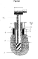
- the end (10a1) of the cylindrical bearing (10a) of the guide device terminates at its end by a blunt bevel, to repel the tissue, as shown in FIG. figure 4 .
- the guide device according to the invention will be chosen with a higher part height (Z1) so that it descends to gingival or bone contact by flaring the mucosa.
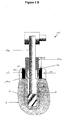
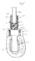
- the figure 3-B presents the device according to the invention in real situation at the beginning of surgery, the guiding device (10) sliding along the axis of the tool of the drill type (15), in its upper part or zone (Z1) in continuously controlling the depth of penetration of the working portion of the drill into the bone site by locking the guide device in the ring associated with the surgical guide and the variable height of the the portion or zone (Z1) having the cylindrical bearing adapted to the diameter of the axis of the cutting or preparation tool.
- the figure 4 illustrates the guide device adapted to the final bone site preparation diameter and for implant placement.
- the guiding device according to the invention will be chosen with a height of the portion of the zone Z2 which is higher in order to obtain a contact with a guiding device - mucosa or gingiva: the bevelling of the guiding device makes it possible to let the tissues outside.
Landscapes
- Health & Medical Sciences (AREA)
- Oral & Maxillofacial Surgery (AREA)
- Life Sciences & Earth Sciences (AREA)
- Dentistry (AREA)
- Veterinary Medicine (AREA)
- Surgery (AREA)
- Public Health (AREA)
- General Health & Medical Sciences (AREA)
- Animal Behavior & Ethology (AREA)
- Heart & Thoracic Surgery (AREA)
- Medical Informatics (AREA)
- Molecular Biology (AREA)
- Biomedical Technology (AREA)
- Engineering & Computer Science (AREA)
- Nuclear Medicine, Radiotherapy & Molecular Imaging (AREA)
- Orthopedic Medicine & Surgery (AREA)
- Epidemiology (AREA)
- Surgical Instruments (AREA)
- Dental Prosthetics (AREA)
- Prostheses (AREA)
- Dental Tools And Instruments Or Auxiliary Dental Instruments (AREA)
Claims (8)
- Vorrichtung zur Knochenführung und -modellierung (UG), die einen zylindrischen Monoblockkörpers (10), der mit einer Bohrung für die axiale Führung eines Bohrers (15) versehen ist, und einen Ring (13) umfasst, wobei das untere Ende des zylindrischen Monoblockkörpers (10) abgefast ist, um Gewebe nach außen zu biegen, wobei der zylindrische Monoblockkörper (10) zwei zylindrische Bereiche (10a-10b) besitzt, die zueinander benachbart und konzentrisch sind, wobei ein erster so genannter innerer Bereich (10b) den Durchgang und die Führung der Achse (15a) des Bohrwerkzeugs (15) zulässt und wobei ein zweiter so genannter äußerer Bereich (10a) wenigstens zwei Indexierungsmittel (11-12) enthält, die sich in komplementären Formen (13a) einstellen, die an dem Ring (13), der mit einer chirurgischen Führung (14) fest verbunden werden kann, gebildet sind, dadurch gekennzeichnet, dass die Indexierungsmittel (11-12) die Blockierung der Führungsvorrichtung in Tiefenrichtung und rotatorisch bei der Positionierung des Monoblockkörpers (10) in dem mit der chirurgischen Führung fest verbundenen Ring (13) sicherstellen und der innere Bereich (10b) einen Außendurchmesser besitzt, der mit dem Innendurchmesser des äußeren Bereichs (10a) übereinstimmt, und einen Innendurchmesser besitzt, der von dem Innendurchmesser des äußeren Bereichs (10a) verschieden ist, derart, dass der äußere zylindrische Bereich (10a) zwei in Höhenrichtung aufeinander folgende Zonen (Z1-Z2) definiert, wobei die Zone (Z1) der freie Teil ist, der aus dem zylindrischen Körper (10) austritt, nachdem er an dem Ring (13) positioniert worden ist, wobei die Zone (Z2) der innere Teil ist, der sich in dem Ring (13) befindet, nachdem der zylindrische Körper (10) in dem Ring (13) positioniert worden ist, wobei die Zone (Z1) eine veränderliche Höhe hat, um die Tiefe des Bohrens und/oder Präparierens des Zahnfleisches zu steuern, und wobei die Zone (Z2) eine konstante Höhe besitzt.
- Vorrichtung nach Anspruch 1, dadurch gekennzeichnet, dass die zwei Bereiche (10a) und (10b) unterschiedliche Höhen haben.
- Vorrichtung nach Anspruch 1, dadurch gekennzeichnet, dass die zwei Bereiche (10a) und (10b) die gleiche Höhe haben.
- Vorrichtung nach Anspruch 1, dadurch gekennzeichnet, dass die Höhe der Zone (Z1) im Bereich von 3 bis 15 mm liegt und die konstante Höhe der Zone (Z2) etwa 5 mm beträgt.
- Vorrichtung nach einem der Ansprüche 1 bis 4, dadurch gekennzeichnet, dass die Indexierungsmittel (11-12) aus äußeren Nasen, Gleitbahnen oder Ansätzen bestehen, die in eine äquivalente Anzahl komplementärer Formen des Typs Rinnen oder Kerben oder Umfangsnuten, die an dem Ring (13) gebildet sind, einrasten.
- Vorrichtung nach Anspruch 5, dadurch gekennzeichnet, dass die äußeren Nasen, Gleitbahnen oder Ansätze diametral entgegengesetzt sind.
- Vorrichtung nach einem der Ansprüche 1 bis 6, dadurch gekennzeichnet, dass sie aus chirurgischem Stahl, Titan oder einer Titanlegierung, aus PIC oder aus POM (Polyoxymethacrylat), aus Keramik oder aus Zirkon oder aus ihren Oxiden erhalten wird.
- Vorrichtung nach einem der Ansprüche 1 bis 7, dadurch gekennzeichnet, dass die Biegung, die das Ende (10a1) des inneren Bereichs (10a) bildet, abgestumpft ist.
Applications Claiming Priority (2)
| Application Number | Priority Date | Filing Date | Title |
|---|---|---|---|
| FR0700011A FR2910804B1 (fr) | 2007-01-02 | 2007-01-02 | Dispositif de guidage et de modelage osseux pour la preparation de sites osseux en chirurgie |
| PCT/FR2007/052618 WO2008087356A2 (fr) | 2007-01-02 | 2007-12-24 | Dispositif de guidage et de modelage osseux pour la preparation de sites osseux en chirurgie implantaire |
Publications (2)
| Publication Number | Publication Date |
|---|---|
| EP2120772A2 EP2120772A2 (de) | 2009-11-25 |
| EP2120772B1 true EP2120772B1 (de) | 2013-07-17 |
Family
ID=38283540
Family Applications (1)
| Application Number | Title | Priority Date | Filing Date |
|---|---|---|---|
| EP07872027.3A Not-in-force EP2120772B1 (de) | 2007-01-02 | 2007-12-24 | Knochenmodellierung und führungsvorrichtung zur vorbereitung von knochenstellen zur implantatsoperation |
Country Status (5)
| Country | Link |
|---|---|
| US (1) | US20100129768A1 (de) |
| EP (1) | EP2120772B1 (de) |
| ES (1) | ES2431335T3 (de) |
| FR (1) | FR2910804B1 (de) |
| WO (1) | WO2008087356A2 (de) |
Families Citing this family (17)
| Publication number | Priority date | Publication date | Assignee | Title |
|---|---|---|---|---|
| FR2925289B1 (fr) * | 2007-12-20 | 2011-01-21 | Anthogyr Sa | Dispositif de centrage et de guidage d'un foret de piece a main dentaire |
| DE202008012049U1 (de) * | 2008-09-10 | 2009-02-19 | Gäßler Zahntechnik GmbH | Zahnmedizinisches Bohrführungssystem |
| WO2011027689A1 (ja) * | 2009-09-01 | 2011-03-10 | Akutsu Isao | インプラント用器具及びインプラント用器具のガイドシステム |
| EP2332486A1 (de) * | 2009-12-10 | 2011-06-15 | 2Ingis S.A. | Bohrschablone und Festigungsmittel für eine solche Schablone |
| US20110238071A1 (en) * | 2010-03-24 | 2011-09-29 | Alain Fernandez-Scoma | Drill assistance kit for implant hole in a bone structure |
| TWI448276B (zh) * | 2010-11-26 | 2014-08-11 | Po Kun Cheng | 牙齒定位模板及其製造方法 |
| ITFI20110130A1 (it) * | 2011-07-01 | 2013-01-02 | Leone Spa | Sistema di guida chirurgica per implantologia dentale e procedimento per la realizzazione di guide chirurgiche per implantologia dentale. |
| AT513103B1 (de) * | 2012-06-28 | 2014-07-15 | Jeder Gmbh | Einrichtung zum durchdringenden Verlängern einer in hartes Gewebe, insbesondere den Kieferknochen, eingebrachten Sackbohrung |
| WO2014117790A1 (de) * | 2013-01-31 | 2014-08-07 | Heinz-Dieter Unger | Implantateinrichtung, verpackung und implantierverfahren |
| US10016255B2 (en) * | 2013-08-26 | 2018-07-10 | Elos Medtech Timmersdala Ab | Dental surgery device |
| WO2015030652A1 (en) | 2013-08-26 | 2015-03-05 | Elos Medtech Timmersdala Ab | Dental drill system |
| US20150359479A1 (en) * | 2014-04-01 | 2015-12-17 | FPJ Enterprises, LLC | Methods for Obtaining Information Relative to a Specific Linear Trajectory |
| US9283055B2 (en) | 2014-04-01 | 2016-03-15 | FPJ Enterprises, LLC | Method for establishing drill trajectory for dental implants |
| CN105520786A (zh) * | 2016-02-23 | 2016-04-27 | 深圳市速航科技发展有限公司 | 一种超声根管治疗装置 |
| US20180263727A1 (en) * | 2017-03-15 | 2018-09-20 | Coredent Advancements, LLC | Surgical Guide and Associated Process for Dental Implants |
| EP3934560B1 (de) | 2019-03-08 | 2024-01-24 | Straumann Holding AG | Ein zahnärztliches bohrerführungssystem |
| JP7112138B1 (ja) * | 2021-10-25 | 2022-08-03 | 株式会社ルッキン | 歯科治療用のオステオトーム、穴形成器具、テストポスト、ストッパーエクステンション、歯根膜ガード、水流チューブ |
Family Cites Families (6)
| Publication number | Priority date | Publication date | Assignee | Title |
|---|---|---|---|---|
| US6296483B1 (en) | 1997-03-07 | 2001-10-02 | Universite Joseph Fourier | System for preparing the placing of a dental implant |
| KR100541994B1 (ko) * | 1997-04-25 | 2006-04-12 | 술저 오소패디 악티엔게젤샤프트 | 연골내 또는 골연골의 구멍을 만드는 장치 |
| FR2836372B1 (fr) * | 2002-02-28 | 2004-06-04 | Obl | Procede et dispositif pour la mise en place d'implants dentaires |
| US7935118B2 (en) * | 2002-06-21 | 2011-05-03 | Depuy Products, Inc. | Prosthesis removal cutting guide, cutting tool and method |
| FR2878429A1 (fr) * | 2004-11-29 | 2006-06-02 | Georges Antoine Creps | Dispositif et procede de forage pour l'insertion d'un implant dentaire |
| FR2882250B1 (fr) | 2005-02-24 | 2013-09-27 | Michel Isidori | Dispositifs de guidage et de coupe pour la preparation de sites osseux en chirurgie implantaire |
-
2007
- 2007-01-02 FR FR0700011A patent/FR2910804B1/fr not_active Expired - Fee Related
- 2007-12-24 WO PCT/FR2007/052618 patent/WO2008087356A2/fr not_active Ceased
- 2007-12-24 EP EP07872027.3A patent/EP2120772B1/de not_active Not-in-force
- 2007-12-24 ES ES07872027T patent/ES2431335T3/es active Active
- 2007-12-24 US US12/521,995 patent/US20100129768A1/en not_active Abandoned
Also Published As
| Publication number | Publication date |
|---|---|
| WO2008087356A3 (fr) | 2008-11-06 |
| EP2120772A2 (de) | 2009-11-25 |
| US20100129768A1 (en) | 2010-05-27 |
| FR2910804B1 (fr) | 2010-03-12 |
| WO2008087356A2 (fr) | 2008-07-24 |
| ES2431335T3 (es) | 2013-11-26 |
| FR2910804A1 (fr) | 2008-07-04 |
Similar Documents
| Publication | Publication Date | Title |
|---|---|---|
| EP2120772A2 (de) | Knochenmodellierung und führungsvorrichtung zur vorbereitung von knochenstellen zur implantatsoperation | |
| EP1753365B1 (de) | Massgefertigte implantierbare chirurgische führung und zugehöriges fräswerkzeug und herstellungsverfahren | |
| US5782636A (en) | Bone contouring tool | |
| EP1478298B1 (de) | Verfahren und vorrichtung zum einsetzen von zahnimplantaten | |
| US8398643B2 (en) | Maxillary bone cutting and injection system and method of using the same | |
| EP2196162B1 (de) | Bohrerführung | |
| KR20100066506A (ko) | 임플란트 식립용 천공기구, 핸드피스, 핸드피스용 어댑터 및 서지컬 가이드 | |
| AU2008290807B2 (en) | Drill guide with a limit stop | |
| EP2037834A1 (de) | Verfahren zur herstellung einer knochenprothese oder einer präimplantat-simulation und verwendete ausrüstung | |
| KR101550759B1 (ko) | 치과용 임플란트 키트 | |
| US11576749B2 (en) | Dental surgery method and device | |
| EP4241723A2 (de) | Foret chirurgical | |
| JP6940735B2 (ja) | インプラント用フィクスチャー植立のための方向確認ピンとガイドタップドリルキット | |
| KR102205986B1 (ko) | 임플란트용 트레파인 드릴 | |
| US20090291414A1 (en) | Method for forming a dental implant | |
| US20150313692A1 (en) | Methods and tooling for dental implant | |
| CN111698961B (zh) | 牙科手术方法和装置 | |
| KR102638863B1 (ko) | 치아 임플란트용 드릴장치 | |
| FR2516784A1 (fr) | Nouvel implant, outil pour la mise en place de celui-ci et procede de realisations implantaires | |
| FR2882250A1 (fr) | Dispositifs de guidage et de coupe pour la preparation de sites osseux en chirurgie implantaire | |
| WO2019180673A1 (fr) | Dispositif d'assistance au forage d'un puits pour implant dentaire | |
| GB2578426A (en) | Dental surgery apparatus | |
| US20260041524A1 (en) | Socket shield technique kit | |
| FR2924920A1 (fr) | Guide de percage pour un implant dentaire | |
| EP4018961A1 (de) | Führungsvorrichtung für das einsetzen eines maxillozygomatischen implantats |
Legal Events
| Date | Code | Title | Description |
|---|---|---|---|
| PUAI | Public reference made under article 153(3) epc to a published international application that has entered the european phase |
Free format text: ORIGINAL CODE: 0009012 |
|
| 17P | Request for examination filed |
Effective date: 20090703 |
|
| AK | Designated contracting states |
Kind code of ref document: A2 Designated state(s): AT BE BG CH CY CZ DE DK EE ES FI FR GB GR HU IE IS IT LI LT LU LV MC MT NL PL PT RO SE SI SK TR |
|
| DAX | Request for extension of the european patent (deleted) | ||
| 17Q | First examination report despatched |
Effective date: 20110421 |
|
| GRAP | Despatch of communication of intention to grant a patent |
Free format text: ORIGINAL CODE: EPIDOSNIGR1 |
|
| GRAS | Grant fee paid |
Free format text: ORIGINAL CODE: EPIDOSNIGR3 |
|
| GRAA | (expected) grant |
Free format text: ORIGINAL CODE: 0009210 |
|
| AK | Designated contracting states |
Kind code of ref document: B1 Designated state(s): AT BE BG CH CY CZ DE DK EE ES FI FR GB GR HU IE IS IT LI LT LU LV MC MT NL PL PT RO SE SI SK TR |
|
| REG | Reference to a national code |
Ref country code: GB Ref legal event code: FG4D Free format text: NOT ENGLISH |
|
| REG | Reference to a national code |
Ref country code: CH Ref legal event code: EP |
|
| REG | Reference to a national code |
Ref country code: IE Ref legal event code: FG4D Free format text: LANGUAGE OF EP DOCUMENT: FRENCH |
|
| REG | Reference to a national code |
Ref country code: AT Ref legal event code: REF Ref document number: 621687 Country of ref document: AT Kind code of ref document: T Effective date: 20130815 |
|
| REG | Reference to a national code |
Ref country code: DE Ref legal event code: R096 Ref document number: 602007031777 Country of ref document: DE Effective date: 20130919 |
|
| REG | Reference to a national code |
Ref country code: ES Ref legal event code: FG2A Ref document number: 2431335 Country of ref document: ES Kind code of ref document: T3 Effective date: 20131126 |
|
| REG | Reference to a national code |
Ref country code: AT Ref legal event code: MK05 Ref document number: 621687 Country of ref document: AT Kind code of ref document: T Effective date: 20130717 |
|
| REG | Reference to a national code |
Ref country code: NL Ref legal event code: VDEP Effective date: 20130717 |
|
| REG | Reference to a national code |
Ref country code: LT Ref legal event code: MG4D |
|
| PG25 | Lapsed in a contracting state [announced via postgrant information from national office to epo] |
Ref country code: LT Free format text: LAPSE BECAUSE OF FAILURE TO SUBMIT A TRANSLATION OF THE DESCRIPTION OR TO PAY THE FEE WITHIN THE PRESCRIBED TIME-LIMIT Effective date: 20130717 Ref country code: IS Free format text: LAPSE BECAUSE OF FAILURE TO SUBMIT A TRANSLATION OF THE DESCRIPTION OR TO PAY THE FEE WITHIN THE PRESCRIBED TIME-LIMIT Effective date: 20131117 Ref country code: SE Free format text: LAPSE BECAUSE OF FAILURE TO SUBMIT A TRANSLATION OF THE DESCRIPTION OR TO PAY THE FEE WITHIN THE PRESCRIBED TIME-LIMIT Effective date: 20130717 Ref country code: CY Free format text: LAPSE BECAUSE OF FAILURE TO SUBMIT A TRANSLATION OF THE DESCRIPTION OR TO PAY THE FEE WITHIN THE PRESCRIBED TIME-LIMIT Effective date: 20130814 Ref country code: PT Free format text: LAPSE BECAUSE OF FAILURE TO SUBMIT A TRANSLATION OF THE DESCRIPTION OR TO PAY THE FEE WITHIN THE PRESCRIBED TIME-LIMIT Effective date: 20131118 Ref country code: AT Free format text: LAPSE BECAUSE OF FAILURE TO SUBMIT A TRANSLATION OF THE DESCRIPTION OR TO PAY THE FEE WITHIN THE PRESCRIBED TIME-LIMIT Effective date: 20130717 |
|
| PG25 | Lapsed in a contracting state [announced via postgrant information from national office to epo] |
Ref country code: PL Free format text: LAPSE BECAUSE OF FAILURE TO SUBMIT A TRANSLATION OF THE DESCRIPTION OR TO PAY THE FEE WITHIN THE PRESCRIBED TIME-LIMIT Effective date: 20130717 Ref country code: NL Free format text: LAPSE BECAUSE OF FAILURE TO SUBMIT A TRANSLATION OF THE DESCRIPTION OR TO PAY THE FEE WITHIN THE PRESCRIBED TIME-LIMIT Effective date: 20130717 Ref country code: FI Free format text: LAPSE BECAUSE OF FAILURE TO SUBMIT A TRANSLATION OF THE DESCRIPTION OR TO PAY THE FEE WITHIN THE PRESCRIBED TIME-LIMIT Effective date: 20130717 Ref country code: GR Free format text: LAPSE BECAUSE OF FAILURE TO SUBMIT A TRANSLATION OF THE DESCRIPTION OR TO PAY THE FEE WITHIN THE PRESCRIBED TIME-LIMIT Effective date: 20131018 Ref country code: LV Free format text: LAPSE BECAUSE OF FAILURE TO SUBMIT A TRANSLATION OF THE DESCRIPTION OR TO PAY THE FEE WITHIN THE PRESCRIBED TIME-LIMIT Effective date: 20130717 Ref country code: SI Free format text: LAPSE BECAUSE OF FAILURE TO SUBMIT A TRANSLATION OF THE DESCRIPTION OR TO PAY THE FEE WITHIN THE PRESCRIBED TIME-LIMIT Effective date: 20130717 |
|
| PG25 | Lapsed in a contracting state [announced via postgrant information from national office to epo] |
Ref country code: CY Free format text: LAPSE BECAUSE OF FAILURE TO SUBMIT A TRANSLATION OF THE DESCRIPTION OR TO PAY THE FEE WITHIN THE PRESCRIBED TIME-LIMIT Effective date: 20130717 |
|
| PG25 | Lapsed in a contracting state [announced via postgrant information from national office to epo] |
Ref country code: RO Free format text: LAPSE BECAUSE OF FAILURE TO SUBMIT A TRANSLATION OF THE DESCRIPTION OR TO PAY THE FEE WITHIN THE PRESCRIBED TIME-LIMIT Effective date: 20130717 Ref country code: DK Free format text: LAPSE BECAUSE OF FAILURE TO SUBMIT A TRANSLATION OF THE DESCRIPTION OR TO PAY THE FEE WITHIN THE PRESCRIBED TIME-LIMIT Effective date: 20130717 Ref country code: SK Free format text: LAPSE BECAUSE OF FAILURE TO SUBMIT A TRANSLATION OF THE DESCRIPTION OR TO PAY THE FEE WITHIN THE PRESCRIBED TIME-LIMIT Effective date: 20130717 Ref country code: CZ Free format text: LAPSE BECAUSE OF FAILURE TO SUBMIT A TRANSLATION OF THE DESCRIPTION OR TO PAY THE FEE WITHIN THE PRESCRIBED TIME-LIMIT Effective date: 20130717 Ref country code: EE Free format text: LAPSE BECAUSE OF FAILURE TO SUBMIT A TRANSLATION OF THE DESCRIPTION OR TO PAY THE FEE WITHIN THE PRESCRIBED TIME-LIMIT Effective date: 20130717 |
|
| PLBE | No opposition filed within time limit |
Free format text: ORIGINAL CODE: 0009261 |
|
| STAA | Information on the status of an ep patent application or granted ep patent |
Free format text: STATUS: NO OPPOSITION FILED WITHIN TIME LIMIT |
|
| 26N | No opposition filed |
Effective date: 20140422 |
|
| BERE | Be: lapsed |
Owner name: ISIDORI, MICHEL Effective date: 20131231 |
|
| REG | Reference to a national code |
Ref country code: DE Ref legal event code: R097 Ref document number: 602007031777 Country of ref document: DE Effective date: 20140422 Ref country code: CH Ref legal event code: PL |
|
| PG25 | Lapsed in a contracting state [announced via postgrant information from national office to epo] |
Ref country code: LU Free format text: LAPSE BECAUSE OF FAILURE TO SUBMIT A TRANSLATION OF THE DESCRIPTION OR TO PAY THE FEE WITHIN THE PRESCRIBED TIME-LIMIT Effective date: 20131224 Ref country code: MC Free format text: LAPSE BECAUSE OF FAILURE TO SUBMIT A TRANSLATION OF THE DESCRIPTION OR TO PAY THE FEE WITHIN THE PRESCRIBED TIME-LIMIT Effective date: 20130717 |
|
| REG | Reference to a national code |
Ref country code: IE Ref legal event code: MM4A |
|
| PG25 | Lapsed in a contracting state [announced via postgrant information from national office to epo] |
Ref country code: BE Free format text: LAPSE BECAUSE OF NON-PAYMENT OF DUE FEES Effective date: 20131231 Ref country code: CH Free format text: LAPSE BECAUSE OF NON-PAYMENT OF DUE FEES Effective date: 20131231 Ref country code: LI Free format text: LAPSE BECAUSE OF NON-PAYMENT OF DUE FEES Effective date: 20131231 Ref country code: IE Free format text: LAPSE BECAUSE OF NON-PAYMENT OF DUE FEES Effective date: 20131224 |
|
| PG25 | Lapsed in a contracting state [announced via postgrant information from national office to epo] |
Ref country code: TR Free format text: LAPSE BECAUSE OF FAILURE TO SUBMIT A TRANSLATION OF THE DESCRIPTION OR TO PAY THE FEE WITHIN THE PRESCRIBED TIME-LIMIT Effective date: 20130717 |
|
| PG25 | Lapsed in a contracting state [announced via postgrant information from national office to epo] |
Ref country code: BG Free format text: LAPSE BECAUSE OF FAILURE TO SUBMIT A TRANSLATION OF THE DESCRIPTION OR TO PAY THE FEE WITHIN THE PRESCRIBED TIME-LIMIT Effective date: 20130717 Ref country code: HU Free format text: LAPSE BECAUSE OF FAILURE TO SUBMIT A TRANSLATION OF THE DESCRIPTION OR TO PAY THE FEE WITHIN THE PRESCRIBED TIME-LIMIT; INVALID AB INITIO Effective date: 20071224 |
|
| PG25 | Lapsed in a contracting state [announced via postgrant information from national office to epo] |
Ref country code: MT Free format text: LAPSE BECAUSE OF FAILURE TO SUBMIT A TRANSLATION OF THE DESCRIPTION OR TO PAY THE FEE WITHIN THE PRESCRIBED TIME-LIMIT Effective date: 20130717 |
|
| REG | Reference to a national code |
Ref country code: FR Ref legal event code: PLFP Year of fee payment: 10 |
|
| REG | Reference to a national code |
Ref country code: FR Ref legal event code: PLFP Year of fee payment: 9 |
|
| PGFP | Annual fee paid to national office [announced via postgrant information from national office to epo] |
Ref country code: DE Payment date: 20171212 Year of fee payment: 11 |
|
| REG | Reference to a national code |
Ref country code: FR Ref legal event code: PLFP Year of fee payment: 11 |
|
| PGFP | Annual fee paid to national office [announced via postgrant information from national office to epo] |
Ref country code: IT Payment date: 20171214 Year of fee payment: 11 Ref country code: GB Payment date: 20171219 Year of fee payment: 11 |
|
| PGFP | Annual fee paid to national office [announced via postgrant information from national office to epo] |
Ref country code: ES Payment date: 20180129 Year of fee payment: 11 |
|
| PGFP | Annual fee paid to national office [announced via postgrant information from national office to epo] |
Ref country code: FR Payment date: 20180210 Year of fee payment: 11 |
|
| REG | Reference to a national code |
Ref country code: DE Ref legal event code: R119 Ref document number: 602007031777 Country of ref document: DE |
|
| GBPC | Gb: european patent ceased through non-payment of renewal fee |
Effective date: 20181224 |
|
| PG25 | Lapsed in a contracting state [announced via postgrant information from national office to epo] |
Ref country code: FR Free format text: LAPSE BECAUSE OF NON-PAYMENT OF DUE FEES Effective date: 20181231 Ref country code: DE Free format text: LAPSE BECAUSE OF NON-PAYMENT OF DUE FEES Effective date: 20190702 Ref country code: IT Free format text: LAPSE BECAUSE OF NON-PAYMENT OF DUE FEES Effective date: 20181224 |
|
| PG25 | Lapsed in a contracting state [announced via postgrant information from national office to epo] |
Ref country code: GB Free format text: LAPSE BECAUSE OF NON-PAYMENT OF DUE FEES Effective date: 20181224 |
|
| REG | Reference to a national code |
Ref country code: ES Ref legal event code: FD2A Effective date: 20200205 |
|
| PG25 | Lapsed in a contracting state [announced via postgrant information from national office to epo] |
Ref country code: ES Free format text: LAPSE BECAUSE OF NON-PAYMENT OF DUE FEES Effective date: 20181225 |