EP1445824A1 - Partie d'un boítier d'appareil de communication radio portable fonctionnant comme une antenne. - Google Patents
Partie d'un boítier d'appareil de communication radio portable fonctionnant comme une antenne. Download PDFInfo
- Publication number
- EP1445824A1 EP1445824A1 EP04002136A EP04002136A EP1445824A1 EP 1445824 A1 EP1445824 A1 EP 1445824A1 EP 04002136 A EP04002136 A EP 04002136A EP 04002136 A EP04002136 A EP 04002136A EP 1445824 A1 EP1445824 A1 EP 1445824A1
- Authority
- EP
- European Patent Office
- Prior art keywords
- radio communication
- housing
- portable radio
- communication apparatus
- electrical conductor
- Prior art date
- Legal status (The legal status is an assumption and is not a legal conclusion. Google has not performed a legal analysis and makes no representation as to the accuracy of the status listed.)
- Withdrawn
Links
Images


Classifications
-
- C—CHEMISTRY; METALLURGY
- C11—ANIMAL OR VEGETABLE OILS, FATS, FATTY SUBSTANCES OR WAXES; FATTY ACIDS THEREFROM; DETERGENTS; CANDLES
- C11C—FATTY ACIDS FROM FATS, OILS OR WAXES; CANDLES; FATS, OILS OR FATTY ACIDS BY CHEMICAL MODIFICATION OF FATS, OILS, OR FATTY ACIDS OBTAINED THEREFROM
- C11C5/00—Candles
- C11C5/002—Ingredients
- C11C5/004—Ingredients dyes, pigments; products giving a coloured flame
-
- H—ELECTRICITY
- H01—ELECTRIC ELEMENTS
- H01Q—ANTENNAS, i.e. RADIO AERIALS
- H01Q5/00—Arrangements for simultaneous operation of antennas on two or more different wavebands, e.g. dual-band or multi-band arrangements
-
- C—CHEMISTRY; METALLURGY
- C11—ANIMAL OR VEGETABLE OILS, FATS, FATTY SUBSTANCES OR WAXES; FATTY ACIDS THEREFROM; DETERGENTS; CANDLES
- C11C—FATTY ACIDS FROM FATS, OILS OR WAXES; CANDLES; FATS, OILS OR FATTY ACIDS BY CHEMICAL MODIFICATION OF FATS, OILS, OR FATTY ACIDS OBTAINED THEREFROM
- C11C5/00—Candles
- C11C5/006—Candles wicks, related accessories
-
- H—ELECTRICITY
- H01—ELECTRIC ELEMENTS
- H01Q—ANTENNAS, i.e. RADIO AERIALS
- H01Q1/00—Details of, or arrangements associated with, antennas
- H01Q1/12—Supports; Mounting means
- H01Q1/22—Supports; Mounting means by structural association with other equipment or articles
- H01Q1/24—Supports; Mounting means by structural association with other equipment or articles with receiving set
-
- H—ELECTRICITY
- H01—ELECTRIC ELEMENTS
- H01Q—ANTENNAS, i.e. RADIO AERIALS
- H01Q1/00—Details of, or arrangements associated with, antennas
- H01Q1/27—Adaptation for use in or on movable bodies
-
- H—ELECTRICITY
- H01—ELECTRIC ELEMENTS
- H01Q—ANTENNAS, i.e. RADIO AERIALS
- H01Q1/00—Details of, or arrangements associated with, antennas
- H01Q1/36—Structural form of radiating elements, e.g. cone, spiral, umbrella; Particular materials used therewith
- H01Q1/38—Structural form of radiating elements, e.g. cone, spiral, umbrella; Particular materials used therewith formed by a conductive layer on an insulating support
-
- H—ELECTRICITY
- H01—ELECTRIC ELEMENTS
- H01Q—ANTENNAS, i.e. RADIO AERIALS
- H01Q3/00—Arrangements for changing or varying the orientation or the shape of the directional pattern of the waves radiated from an antenna or antenna system
- H01Q3/44—Arrangements for changing or varying the orientation or the shape of the directional pattern of the waves radiated from an antenna or antenna system varying the electric or magnetic characteristics of reflecting, refracting, or diffracting devices associated with the radiating element
-
- H—ELECTRICITY
- H01—ELECTRIC ELEMENTS
- H01Q—ANTENNAS, i.e. RADIO AERIALS
- H01Q5/00—Arrangements for simultaneous operation of antennas on two or more different wavebands, e.g. dual-band or multi-band arrangements
- H01Q5/30—Arrangements for providing operation on different wavebands
- H01Q5/307—Individual or coupled radiating elements, each element being fed in an unspecified way
- H01Q5/342—Individual or coupled radiating elements, each element being fed in an unspecified way for different propagation modes
- H01Q5/357—Individual or coupled radiating elements, each element being fed in an unspecified way for different propagation modes using a single feed point
- H01Q5/364—Creating multiple current paths
-
- H—ELECTRICITY
- H01—ELECTRIC ELEMENTS
- H01Q—ANTENNAS, i.e. RADIO AERIALS
- H01Q5/00—Arrangements for simultaneous operation of antennas on two or more different wavebands, e.g. dual-band or multi-band arrangements
- H01Q5/40—Imbricated or interleaved structures; Combined or electromagnetically coupled arrangements, e.g. comprising two or more non-connected fed radiating elements
Definitions
- the present invention relates to a portable radio communication apparatus including a housing, and in particular, relates to a potable radio communication apparatus provided with a part of housing operating as an antenna.
- portable radio communication apparatuses such as cellular phones have been increasingly made smaller in size and thinner.
- the portable radio communication apparatuses have been not only used as conventional cellular phones but also transformed to data terminal apparatuses for transmitting and receiving E-mails and for viewing web pages through WWW (World Wide Web). Due to this, liquid crystal displays have been made larger in size.
- folding cellular phone terminals which are considered to be suited to make the portable radio communication apparatuses smaller in size and make the liquid crystal displays larger in size, have been spread as disclosed in the following publications:
- an antenna for use in the conventional portable radio communication apparatus requires an antenna-dedicated electrically conductive part, and then, requires a space occupied by the conductive part. Due to this, the portable radio communication apparatus cannot be made thinner. Besides, if the antenna is constituted by using a printed wiring board or the like, the material cost is required for the elements, thereby disadvantageously increasing the manufacturing cost thereof.
- a portable radio communication apparatus including a housing. At least one part of the housing is formed as a housing electrical conductor portion by an electrically conductive material, and the housing electrical conductor portion is connected with a radio communication circuit of the portable radio communication apparatus so as to operate as at least one part of an antenna of the radio communication circuit.
- the antenna is preferably an unbalanced type antenna.
- the portable radio communication apparatus is preferably a straight type portable radio communication apparatus.
- the portable radio communication apparatus is preferably a slide type portable radio communication apparatus in which an upper housing and a lower housing are slidable through a sliding mechanism, and at least one part of at least one of the upper housing and the lower housing is formed as a housing electrical conductor portion by an electrically conductive material.
- the portable radio communication apparatus is preferably a folding portable radio communication apparatus in which an upper housing and a lower housing are foldable through a hinge portion, and at least one part of at least one of the upper housing and the lower housing is formed as a housing electrical conductor portion by an electrically conductive material.
- the housing electrical conductor portion is preferably made by forming an electrical conductor layer on a dielectric housing which is at least one part of the housing. Further, the electrical conductor layer is preferably made by forming an electrical conductor pattern on the dielectric housing.
- the electrical conductor layer preferably includes electrical conductor patterns different from each other on both surfaces of the dielectric housing, respectively, so that the antenna operates in a plurality of frequency bands.
- the electrical conductor layer preferably includes a plurality of electrical conductor portions having electric lengths different from each other, respectively, so that the antenna operates in a plurality of frequency bands.
- the above-mentioned portable radio communication apparatus preferably further includes one of a slot and a slit which are formed in the electrical conductor layer.
- the upper housing preferably includes an upper first housing portion and an upper second housing portion, and at least one of the upper first housing portion and the upper second housing portion is formed as a housing electrical conductor portion by an electrically conductive material so that the housing electrical conductor portion operates as at least one part of the antenna of the portable radio communication apparatus.
- the lower housing preferably includes a lower first housing portion and a lower second housing portion, and at least one of the lower first housing portion and the lower second housing portion is formed as a housing electrical conductor portion by an electrically conductive material so that the housing electrical conductor portion operates as at least one part of the antenna of the portable radio communication apparatus.
- At least one part of the hinge portion preferably is formed as a hinge electrical conductor portion by an electrically conductive material, and the hinge electrical conductor portion is connected with the radio communication circuit of the portable radio communication apparatus so as to operate as at least one part of the antenna of the radio communication circuit.
- At least one part of the hinge portion is preferably formed as a hinge electrical conductor portion by an electrically conductive material so that the hinge electrical conductor portion operates as a parasitic element of the antenna of the radio communication circuit.
- the hinge portion is preferably made to be rotatable in at least biaxial directions.
- the above-mentioned portable radio communication apparatus preferably further includes an electrically insulating layer formed on the hinge portion.
- the above-mentioned portable radio communication apparatus preferably further includes a plurality of reactance elements having a plurality of reactance values different from each other, respectively, and a switching device for selectively switching over the plurality of reactance elements so as to connect selected one of the reactance elements with the housing electrical conductor portion.
- the above-mentioned portable radio communication apparatus preferably includes a plurality of reactance elements having a plurality of reactance values different from each other, respectively, and a switching device for selectively switching over the plurality of reactance elements so as to connect selected one of the reactance elements with the housing electrical conductor portion through the hinge electrical conductor portion.
- the switching device preferably selectively switches over the plurality of reactance elements in accordance with whether the portable radio communication apparatus is in either one of an open state and a closed state thereof.
- the switching device preferably selectively switches over the plurality of reactance elements in accordance with a plurality of operating frequency bands of the portable radio communication apparatus.
- the switching device preferably selectively switches over the plurality of reactance elements in accordance with either one of transmission and receiving of the portable radio communication apparatus.
- the housing electrical conductor portion is preferably made of one of a dielectric material and a magnetic material, and the housing electrical conductor portion is connected with the radio communication circuit through an electrical insulator having a predetermined capacitance so that a radio signal from the radio communication circuit is fed through the capacitance of the electrical insulator to the housing electrical conductor portion.
- the above-mentioned portable radio communication apparatus preferably further includes a thin-film-shaped electrically insulating sheet formed on the upper housing having the housing electrical conductor portion, and the thin-film-shaped electrically insulating sheet is made of one of a dielectric material and a magnetic material.
- the portable radio communication apparatus of the present invention at least one part of the housing is constituted to serve as the antenna element. Therefore, it is advantageously possible to increase the strength of the portable radio communication apparatus against the impact such as that upon the user's dropping the same apparatus. In addition, since it is unnecessary to secure the space occupied by the antenna element, the number of parts can be decreased, and the portable radio communication apparatus can be made thinner and lighter in weight as compared with the conventional portable radio communication apparatus.
- the antenna apparatus can be made larger in size and the antenna gain thereof can be further improved. Additionally, by bonding the thin-film-shaped electrically insulating sheet made of the dielectric material or the magnetic material onto the surface of the upper first housing portion, the distance between the human body and the antenna apparatus can be set larger, and the decrease of the antenna gain caused by the electromagnetic influence of the human body can be suppressed during a telephone conversation.
- Fig. 1A is a plan view of a folding portable radio communication apparatus in an open state thereof according to a first preferred embodiment of the present invention.
- Fig. 1B is a side view of the portable radio communication apparatus shown in Fig. 1A.
- Fig. 1C is a plan view of an antenna element 112 for use in the portable radio communication apparatus shown in Figs. 1A and 1B.
- the portable radio communication apparatus includes an upper housing 102 and a lower housing 103, where the housings 102 and 103 are connected with each other through a circular cylindrical uniaxial hinge portion 104, so as to be foldable through the circular cylindrical uniaxial hinge portion 104.
- the upper housing 102 includes an upper first housing portion 102a arranged on the inside thereof, and an upper second housing portion 102b arranged on the outside thereof. These upper first and second housing portions 102a and 102b are bonded and coupled together.
- a surface of the upper first housing portion 102a that opposes to the inside of the same apparatus will be referred to as an inner side surface
- a surface of the upper second housing portion 102b that opposes to the outside of the same apparatus will be referred to as an outer side surface, hereinafter.
- the hinge portion 104 is formed integrally, for example, with the upper first housing portion 102a, is fitted into the central portion of an upper end (located between an upper left end 103p and an upper right end 103q) of the lower housing 103, and is penetrated through a circular cylindrical hollow of the circular cylindrical hinge portion 104.
- the upper housing 102 and the lower housing 103 are rotatable and foldable about the hinge portion 104 by a circular cylindrical shaft (not shown) extending into the upper left end 103p and the upper right end 103q of the lower housing 103.
- the two housing portions 102a and 102b are penetrated into the upper first housing portion 102a from the inner side surface to the outer side surface and screwed by respective screws 113 and 114 on the left and right corner portions of the lower ends to a screw reception portion 115 of the upper second housing portion 102b.
- At least one part of the upper first housing portion 102a is made of an electrically conductive material such as magnesium or zinc, whereas the upper second housing portion 102b is made of an electrically insulating material such as a resin material.
- all of the upper first housing portion 102b may be made of an electrically conductive material.
- the upper first housing portion 102b may be made of an electrically insulating material such as a resin material with an electrical conductor layer made of an electrically conductive material formed on its surface.
- the portion of the upper first housing portion 102a that is formed by at least the electrically conductive material will be referred to as a conductor portion hereinafter.
- a liquid crystal display 105 is located substantially in the central portion of the inner side surface of the upper first housing portion 102a and a sound hole portion 106 is arranged above the liquid crystal display 105 at an upper end portion of the inner side surface of the upper first housing portion 102a.
- a loudspeaker 154 of Fig. 2 that generates a voice of a party on the other end of the communication line during a telephone conversation, is arranged immediately under the sound hole portion 106 so that a user of the portable radio communication apparatus can listen to the voice generated by the loudspeaker 154 through the sound hole portion 106.
- a microphone 107 is arranged on a surface of the lower housing 103 that opposes to the inside (whose surface will be referred to as an inner side surface hereinafter) in the vicinity of a lower end on an opposite side to the hinge portion 104, and a chargeable battery 108 is arranged on a surface of the opposite side to the microphone 107 on the lower housing 103 (whose surface will be referred to as an outer side surface hereinafter).
- a printed wiring board 109 is arranged on the inside of the lower housing 103 and substantially in the central portion of the lower housing 103 in the thickness direction thereof. As shown in Fig. 2, a radio communication circuit 110 that includes a radio receiver 152 and a radio transmitter 153 is formed on the printed wiring board 109.
- a connection point 111 that serves as a feeding point of the radio communication circuit 110 is connected with a screw 113 of the upper housing 102 through an antenna element 122, and the screw 113 is electrically connected with the conductor portion of the upper first housing portion 102a.
- the antenna element 122 is provided so as to extend from the radio communication circuit 110 of the lower housing 103 to the screw 113 through an inside of an upper right end of the lower housing 103, an inside of the hinge portion 104, and an inside of the upper second housing portion 102b.
- an electrical conductor ring 112a having a circular hole 112h is provided on one end of the antenna element 122.
- the screw 113 is penetrated through the circular hole 112h, and contacted and electrically connected with the conductor ring 112a. Therefore, the connection point 111 of the radio communication circuit 110 is electrically connected with the conductor portion of the upper first housing portion 102a through the antenna element 112 and the screw 113, and then, the antenna element 112 and the conductor portion of the upper first housing portion 102a operate as a first antenna element 102A of Fig. 2 of the portable radio communication apparatus.
- a boom portion 910 which is made of a resin material (preferably a flexible resin material) which is curved and generally circular cylindrical, is provided so as to be connected with left and right ends on an upper end surface of the lower housing 103. Namely, both ends of the boom portion 910 are connected with the left and right ends of the upper end surface of the lower housing 103, respectively, so as to be substantially bilaterally symmetric in the width direction or the horizontal direction of the portable radio communication apparatus. In this case, in a space surrounded by the boom portion 910 and the lower housing 103, a penetrating hole (or an air space or gap) 910h is formed.
- an antenna element 901 that operates as a second antenna element of the portable radio communication apparatus and that has a length such as a quarter of wavelength or the like is included in the boom portion 910. Further, the antenna element 901 is electrically connected with a connection point 902 that serves as a feeding point of the radio communication circuit 110 from an inside of the boom portion 910 through an inside of the lower housing 103.
- Fig. 2 is a circuit diagram of the antenna elements 102A and 901 and the radio communication circuit 110 connected with the antenna elements 102A and 901 of the portable radio communication apparatus shown in Fig. 1A.
- the antenna element 102A is connected with a first terminal of a circulator 151 through the connection point 111 and a contact "a" of a switch SW1, and further, the antenna element 901 is connected thereto through the connection point 902 and a contact "b" of the switch SW1.
- a second terminal of the circulator 151 is connected with the radio receiver 152 that includes the loudspeaker 154 and a third terminal thereof is connected with the radio transmitter 153 that includes the microphone 107.
- the operations of the radio receiver 152, the radio transmitter 153, and the switch SW1 are controlled by a controller 150.
- a radio signal received by the antenna element 102A or 901 is inputted to the radio receiver 152 through the switch SW1 and the circulator 151.
- the radio receiver 152 subjects the inputted radio signal to low noise amplification, frequency transform, a demodulation processing, thereby extracting a voice and character data and image data contained in the radio signal from the radio signal, and outputting the extracted data to the loudspeaker 154 and also to the liquid crystal display 105 to display the extracted data on the display 105.
- voice and character data and image data to be transmitted are inputted to the radio transmitter 153 from the microphone 107 or the controller 150.
- the radio transmitter 153 subjects a carrier signal to modulation, frequency transform, power amplification, and the like according to the inputted voice and character data and image data to thereby generate a radio signal, and outputs the radio signal to the antenna element 102A or 901 through the circulator 151 and the switch SW1 to project the radio signal.
- the controller 150 compares, for example, a signal level of the radio signal received at the antenna element 102A with that of the radio signal received at the antenna element 901 and selectively switches over to the antenna element that receives the radio signal at the higher signal level using the switch SW1, thereby executing a reception diversity processing. Further, the controller selects one of the antenna elements based on results of the reception diversity processing to transmit the radio signal from the selected antenna element. Alternatively, by transmitting the radio signal using the both antenna elements 102A and 901 simultaneously and controlling the amplitude and the phase of the radio signal fed to the two antenna elements 102A and 901, the controller 150 may execute a transmission diversity processing.
- the conductor portion of the upper first housing portion 102a that is a part of the upper housing 102 is allowed to operate as a part of the antenna element 102A. Then, this leads to that the number of parts can be decreased while maintaining good antenna characteristics, and the manufacturing cost can be reduced.
- the conductor portion of the upper first housing portion 102a using the electrically conductive material having an excellent mechanical strength such as magnesium or the like, it is possible to increase the strength of the portable radio communication apparatus against the impact such as that upon the user's dropping the same apparatus. Further, since no space occupied by an antenna apparatus is required, the portable radio communication apparatus can be made thinner and lighter in weight than the conventional apparatus. Besides, since an area of the antenna elements can be made larger than a conventional external antenna such as a helical antenna, the maximum value of a current density can be reduced and an SAR (Specific Absorption Rate) can be suppressed to be lower.
- SAR Specific Absorption Rate
- the SAR is a power absorbed by an organic structure having a unit mass when an organism such as a human is put in an electromagnetic field.
- the SAR is classified to a whole-body average SAR and a local SAR.
- the radiofrequency safety guideline specifies, for an ordinary environment (for ordinary people), that an arbitrary six-minute average of the whole-body average SAR is 0.08 W/kg or lower and the local SAR (six-minute average) for an arbitrary structure of 10 g is 2 W/kg or lower (3 W/kg for the limbs).
- the conductor portion of the upper first housing portion 102a is electrically connected with the antenna element 112 by the screw 113.
- the present invention is not limited to this, and they may be electrically connected with each other using the other method such as a soldering method, a crimping terminal connection method or a mechanical forced contact method without using the screw 113.
- the antenna element 102A is constituted by using the conductor portion of the upper first housing portion 102a and the antenna element 112.
- the present invention is not limited to this, and the antenna element 102A may be made of a feeding line such as a coaxial cable so as to feed the radio signal to the antenna element 102A through the feeding line.
- the portable radio communication apparatus includes the two antenna elements 102A and 901.
- the present invention is not limited to this, and the portable radio communication apparatus may not include the boom portion 910 and the antenna element 901.
- the circular cylindrical hinge portion 104 is employed.
- the present invention is not limited to this, and a biaxial hinge portion 704 of Fig. 15A may be employed.
- the boom portion 910 is connected with the lower housing 103.
- the present invention is not limited to this, and the boom portion 910 may be connected with the upper housing 102.
- Fig. 3A is a plan view of an electrically insulating ring 201 employed in a folding portable radio communication apparatus according to a first modified preferred embodiment of the first preferred embodiment according to the present invention.
- Fig. 3B is a side view of the portable radio communication apparatus that includes the insulating ring 201 shown in Fig. 3A.
- Fig. 4 is a circuit diagram showing an equivalent circuit of the antenna apparatus of the folding portable radio communication apparatus shown in Figs. 3A and 3B.
- the antenna element 112 is screwed with the upper first housing portion 102a through the screw 113.
- the electrically insulating ring 201 made of a dielectric material and having a circular hole 201h shown in Fig. 3A may be inserted between the upper first housing portion 102a and an electrical conductor ring 112b (having a larger circular hole than the conductor ring 112a) of the antenna element 112 as shown in Fig. 3B, and this leads to that not only the screwing effect but also a capacitive feeding effect can be attained.
- the screw 113 is not mechanically contacted with the conductor ring 112b of the antenna element 112, and a capacitance of the insulating ring 201 is formed between the screw 113 and the antenna element 112.
- the antenna element 102A is constituted, for example, so that a plurality of inductances L1, L2, ..., and LN is connected with each other by a connection point 102Ac on one end of each inductance.
- the connection point 102Ac is connected with the radio transmitter 153 through an inductance LM of the screw 113, the capacitance C0 of the insulating ring 201, and an inductance L0 of the antenna element 112. Since the antenna element 102A is constituted so that the plural inductances L1, L2, ..., and LN are connected with each other at the connection point 102Ac on one end of each inductance, the portable radio communication apparatus can provide wide band characteristics.
- Fig. 5A is a plan view of a folding portable radio communication apparatus in an open state thereof according to a second modified preferred embodiment of the first preferred embodiment of the present invention.
- Fig. 5B is a side view of the portable radio communication apparatus shown in Fig. 5A.
- a thin-film-shaped electrically insulating seal 301 made of a dielectric material or a magnetic material such as acryl and having a thickness such as about 0.2 to 0.3 mm may be formed on an entire surface or a part of the inside of the upper first housing portion 102a, for example, by adhesion, as shown in Figs. 5A and 5B. This can prevent a part of a human body from directly contacting with the inner side surface of the upper first housing portion 102a that operates as the antenna element 102A, and can lower the decrease in the antenna gain caused by the human body during a telephone conversation.
- the distance between the antenna element 102A and the human body can be set larger, and the SAR can be kept lower.
- a transparent panel or a coating member made of a dielectric material such as a resin material may be employed instead of the insulating seal 301.
- Fig. 6A is a plan view of a folding portable radio communication apparatus in an open state thereof according to a third modified preferred embodiment of the first preferred embodiment of the present invention.
- Fig. 6B is a side view of the portable radio communication apparatus shown in Fig. 6A.
- the portable radio communication apparatus is different from that according to the first preferred embodiment shown in Figs. 1A and 1B, in that the upper first housing portion 102a is divided to a first part 102a-1 and a second part 102a-2.
- the first and second parts 102a-1 and 102a-2 have half the thickness of the upper first housing portion 102a, respectively, and are fitted and bonded together in the vicinity of the lower end of the upper first housing portion 102a at a position where the screw 113 is arranged.
- the screw 113 is screwed with the screw reception portion 115 from the inner side surface of the upper housing 102 through the second part 102a-2 and the first part 102a-1 of the upper first housing portion 102a and the upper second housing portion 102b.
- Fig. 7A is a plan view of a folding portable radio communication apparatus in an open state thereof according to a second preferred embodiment of the present invention.
- Fig. 7B is a side view of the portable radio communication apparatus shown in Fig. 7A.
- the portable radio communication apparatus according to the second preferred embodiment is different from that according to the first preferred embodiment in the following points.
- the portable radio communication apparatus constituted as mentioned above has the same functions and advantageous effects as those of the portable radio communication apparatus according to the first preferred embodiment.
- the portable radio communication apparatus can advantageously suppress the decrease of the antenna gain caused by the electromagnetic influence of the human body.
- the upper first housing portion 102a includes the liquid crystal display 105, it is necessary to secure a high strength of the upper first housing portion 102a against an impact upon the user's dropping the same apparatus. However, it is unnecessary to secure a high strength of the upper second housing portion 102b, thereby increasing the degree of freedom for designing the same apparatus.
- the capacitive feeding to the antenna element 102A may be performed.
- the conductor portion of the upper second housing portion 102b is electrically connected with the antenna element 112 by the screw 113.
- the present invention is not limited to this, and they may be electrically connected with each other using the other method such as the soldering method, the crimping terminal connection method or the mechanical forced contact method without using the screw 113.
- Fig. 8A is a plan view of a folding portable radio communication apparatus in an open state thereof according to a modified preferred embodiment of the second preferred embodiment of the present invention.
- Fig. 8B is a side view of the portable radio communication apparatus shown in Fig. 8A.
- the portable radio communication apparatus is different from that according to the second preferred embodiment shown in Figs. 7A and 7B, in that the upper second housing portion 102b is divided to a first part 102b-1 and a second part 102b-2.
- the first and second parts 102b-1 and 102b-2 have half the thickness of the upper second housing portion 102b, respectively, and are fitted and bonded together in the vicinity of the lower end of the upper second housing portion 102b at a position at which the screw 113 is arranged.
- the screw 113 is screwed with the screw reception portion 115 from the inner side surface of the upper housing 102 through the upper first housing portion 102a, the first part 102b-1 and the second part 102b-2 of the upper second housing portion 102b.
- Fig. 9A is a plan view of a folding portable radio communication apparatus in an open state thereof according to a third preferred embodiment of the present invention.
- Fig. 9B is a side view of the portable radio communication apparatus shown in Fig. 9A.
- Fig. 10A is a perspective view showing a hinge portion 503 for use in the portable radio communication apparatus shown in Figs. 9A and 9B.
- Fig. 10B is a perspective view showing a fitting intrusive circular cylindrical member 505 connected with the hinge portion 503 shown in Fig. 10A and an antenna element 504 connected with the member 505.
- the portable radio communication apparatus is different from that according to the first preferred embodiment shown in Figs. 1A and 1B in the following points.
- the hinge portion 503 is constituted by a circular cylindrical portion 503a and two leg portions 503b and 503c extending from left and right ends of the circular cylindrical portion 503a as being inclined from an upward direction, respectively.
- the leg portions 503b and 503c include circular holes 503bh and 503ch, respectively, so as to penetrate them in the thickness direction thereof in the vicinity of the ends thereof.
- the leg portions 503b and 503c are fitted into the upper second housing portion 102b, and screws 113 and 114 are inserted into the circular holes 503bh and 503ch, respectively. Then, the leg portions 503b and 503c are screwed with the upper second housing portion 102b by the screws 113 and 114.
- one end of the antenna element 504 is connected with a part of a circular cylindrical end surface of the fitting intrusive circular cylindrical member 505.
- the fitting intrusive circular cylindrical member 505 is formed so that an outside diameter of the member 505 is substantially equal to an inside diameter of the circular cylindrical portion 503a of the hinge portion 503, and the fitting intrusive circular cylindrical member 505 is inserted into the circular cylindrical on the inside of the circular cylindrical portion 503a, and is fitted thereinto.
- connection point 111 that serves as the feeding point of the radio communication circuit 110 is electrically connected with the first upper housing portion 102a through the antenna element 504, the fitting intrusive circular cylindrical member 505, and the hinge portion 503. Therefore, the antenna element 504, the fitting intrusive circular cylindrical member 505, the hinge portion 503, and the upper first housing portion 102a can operate as the first antenna element 102A.
- an input impedance for the antenna is preferably low sufficiently to a predetermined impedance such as 50 ⁇ or the like in a predetermined frequency band such as 900 MHz or the like.
- the antenna element 504, the hinge portion 503 and the upper first housing portion 102a operate as the first antenna element 102A. Therefore, as compared with the portable radio communication apparatus in which only the upper first housing portion 102a operates as the antenna element, the antenna apparatus can be made larger in size and the antenna gain can be thereby remarkably improved. Further, it is unnecessary to extend the antenna element 112 toward the upper housing 102 through the inside of the hinge portion 104 as shown in Fig. 1A. Therefore, a diameter of the hinge portion 104 can be made small, and the portable radio communication apparatus can be made thinner. Besides, it is possible to reduce the load on the antenna element 112 when the portable radio communication apparatus is opened or closed, and this leads to improvement of the durability of the portable radio communication apparatus.
- the portable radio communication apparatus may be constituted, so that, for example, the insulating ring 201 of Fig. 3A is inserted between the hinge portion 503 and the fitting intrusive circular cylindrical member 505 and then a radio signal is fed to the antenna element 102A through a capacitance.
- the fitting intrusive circular cylindrical member 503 is arranged in the circular cylindrical inside of the hinge portion 503.
- the present invention is not limited to this, and the antenna element 504 may be formed to extend toward the upper housing 102 as shown in Fig. 1A.
- the upper first housing portion 102a is employed as a part of the antenna element 102A.
- the present invention is not limited to this, and the hinge portion 503 may be electrically connected with the upper second housing portion 102b, and the upper second housing portion 102b may be employed as a component of the antenna elements 102A as shown in Fig. 7A.
- Fig. 11A is a plan view of a folding portable radio communication apparatus in an open state thereof according to a fourth preferred embodiment of the present invention.
- Fig. 11B is a side view of the portable radio communication apparatus shown in Fig. 11A.
- Fig. 12A is a perspective view showing a pair of hinge portions 603 and 604 employed in the portable radio communication apparatus shown in Figs. 11A and 11B.
- Fig. 12B is a perspective view showing (a) a fitting intrusive circular cylindrical member 606 connected with the hinge portion 603 shown in Fig. 12A, (b) an antenna element 605 connected with the fitting intrusive circular cylindrical member 606, (c) a fitting intrusive circular cylindrical member 608 connected with the hinge portion 604 shown in Fig.
- Fig. 13 is a circuit diagram showing a configuration of the radio communication circuit 110 connected with a hinge portion 604 of the portable radio communication apparatus shown in Figs. 11A and 11B.
- the portable radio communication apparatus is different from that according to the third preferred embodiment in the following points:
- the hinge portion 603 is constituted by a circular cylindrical portion 603a and a leg portion 603b, which extends from a circular cylindrical outer peripheral surface of the circular cylindrical portion 603a and has a circular hole 603h.
- the hinge portion 604 is constituted by a circular cylindrical portion 604a and a leg portion 604b, which extends from a circular cylindrical outer peripheral surface of the circular cylindrical portion 604a and has a circular hole 604h.
- the circular cylindrical fitting intrusive member 606, which the antenna element 605 is connected with is inserted and fitted into a circular cylindrical inside of the circular cylindrical portion 603a of the hinge portion 603, and further, the circular cylindrical fitting intrusive member 608, which the antenna element 607 is connected with, is inserted and fitted into a circular cylindrical inside of the circular cylindrical portion 604a of the hinge portion 604.
- the circular cylindrical portion 603a of the hinge portion 603 is inserted and fitted between an upper left end 103p of the lower housing 103 and a protruding circular cylindrical portion 103r, and the leg portion 603b of the hinge portion 603 is inserted and fitted to the upper second housing portion 102b. Then, the screw 113 is inserted into the circular hole 603h, and this leads to that the hinge portion 603 is screwed with the upper housing 102 by the screw 113.
- the circular cylindrical portion 604a of the hinge portion 604 is inserted and fitted between an upper left end 103q of the lower housing 103 and the protruding circular cylindrical portion 103r, and the leg portion 604b of the hinge portion 604 is inserted and fitted to the upper second housing portion 102b. Then, the screw 114 is inserted into the circular hole 604h, and this leads to that the hinge portion 604 is screwed with the upper housing 102 by the screw 114.
- the connection point 111 of the radio communication circuit 110 is connected with the fitting intrusive circular cylindrical member 606 through the antenna element 605 that is provided so as to extend into the lower housing 103.
- the connection point 609 of the radio communication circuit 110 is connected with the fitting intrusive circular cylindrical member 608 through the antenna element 607 that is provided so as to extend into the lower housing 103.
- connection point 111 of the radio communication circuit 110 is electrically connected with the upper first housing 102a through the antenna element 605, the fitting intrusive circular cylindrical member 606, the hinge portion 603, and the screw 113.
- connection point 609 of the radio communication circuit 110 is electrically connected with the upper first housing 102a through the antenna element 607, the fitting intrusive circular cylindrical member 608, the hinge portion 604, and the screw 114.
- a circuit ranging from the antenna element 605 to the upper first housing portion 102a and a circuit ranging from the antenna element 607 to the upper first housing portion 102a constitute the first antenna element 102A.
- the antenna element 102A is connected with one of reactance elements 610 and 611 respectively having reactance values Xa and Xb different from each other, through the connection point 609 and a switch SW2 controlled by a controller 150.
- the fitting intrusive circular cylindrical member 606 is connected with the connection point 111 through the antenna element 605, and the fitting intrusive circular cylindrical member 608 is connected with a terminal 609a of the connection point 609 arranged on the antenna element 607. Further, a terminal 609b of the connection point 609 is connected with the first reactance element 610, and a terminal 609c thereof is connected with the second reactance element 611.
- the switch SW1 of Fig. 2 when the switch SW1 of Fig. 2 is switched over to the contact "a" or the contact "b” thereof to use only the antenna element 102A as the antenna apparatus and the switch SW2 of Fig. 13 is switched over to the contact "a” or the contact "b” thereof, the reactance value of the reactance element connected with the antenna element 102A changes, and then, the resonance frequency of the antenna element 120A changes. Therefore, an operating frequency can be switched over, for example, by time division of transmission and reception.
- the reactance elements 610 and 611 may be selectively switched over.
- a condition of an object located in the vicinity of the antenna element 102A changes depending on whether the portable radio communication apparatus is in an open state or a closed state thereof, and then, the reactance elements 610 and 611 are selectively switched over according to the condition so as to be able to obtain a higher antenna gain.
- the antenna element 102A can operate as a parasitic element.
- the switch SW2 of Fig. 13 is switched over to the contact "a" or the contact "b"
- the reactance value of the reactance element connected with the antenna element 102A changes. Namely, it is possible to change the electric length of the antenna element 102A that operates as a parasitic element for the antenna element 901. Therefore, it is possible to change directivity characteristics of the entire antenna apparatus.
- the two reactance elements 610 and 611 are selectively switched over.
- the present invention is not limited to this, and three or more reactance elements may be selectively switched over.
- the first antenna element 102A is constituted by using the upper first housing portion 102a.
- the present invention is not limited to this, and the first antenna element 102A may be constituted by using the upper second housing portion 102b.
- the hinge portions 603 and 604 made of the electrically conductive material are employed.
- the present invention is not limited to this, and the hinge portions 603 and 604 made of a dielectric material such as a resin material or the like may be employed, and the antenna elements 605 and 607 may be directly and electrically connected with the upper first housing portion 102a.
- Fig. 14A is a plan view of a folding portable radio communication apparatus in an open state thereof according to a modified preferred embodiment of the fourth preferred embodiment according to the present invention.
- Fig. 14B is a side view of the portable radio communication apparatus shown in Fig. 14A.
- the portable radio communication apparatus according to the first modified preferred embodiment of the fourth preferred embodiment is different from that according to the fourth preferred embodiment by including an antenna element 612, instead of the antenna element 607 and the fitting intrusive circular cylindrical member 608.
- the antenna element 612 is formed to extend into the lower housing 103, the hinge portion 603, and the upper second housing portion 102b so as to be connected with the screw 114. Therefore, the connection point 609 of the radio communication circuit 110 is electrically connected with the upper first housing portion 102a through the antenna element 612 and the screw 114.
- the portable radio communication apparatus according to the modified preferred embodiment of the fourth preferred embodiment constituted as mentioned above has the same functions and advantageous effects as those of the portable radio communication apparatus according to the fourth preferred embodiment.
- Fig. 15A is a plan view of a folding portable radio communication apparatus in a closed state thereof according to a fifth preferred embodiment of the present invention.
- Fig. 15B is a side view of the portable radio communication apparatus shown in Fig. 15A.
- Fig. 16 is a plan view of the portable radio communication apparatus when an upper housing 702 of the portable radio communication apparatus shown in Figs. 15A and 15B is rotated counterclockwise by about 45 degrees.
- Fig. 17A is a plan view of the portable radio communication apparatus shown in Figs. 15A and 15B in an open state thereof, and Fig. 17B is a side view of the portable radio communication apparatus shown in Fig. 17A.
- the portable radio communication apparatus according to the fifth preferred embodiment is different from that according to the first preferred embodiment in the following points.
- the upper housing 702 and the lower housing 703 are connected with each other, so that they are foldable through the biaxial hinge portion 704 and the upper housing 702 is rotatable about the biaxial hinge portion 704.
- a key pad 705 is provided almost in the central portion of an inner side surface of the lower housing 703.
- the antenna element 802 is provided so as to extend from the inside of the lower housing 703 toward the upper housing 702 through the inside of the biaxial hinge portion 704.
- a connection point 801 (corresponding to the connection point 110 shown in Figs.
- the antenna element 802 and the upper first housing portion 702a constitute the first antenna element 702A in a manner similar to the antenna element 102A of the first preferred embodiment.
- Fig. 18 is a circuit diagram showing a configuration of the antenna elements 702A and 901 and the radio communication circuit 110 connected with the antenna elements 702A and 901 of the portable radio communication apparatus shown in Fig. 17A.
- the antenna element 702A is electrically connected with the contact "a" of the switch SW1 through the connection point 801.
- the other circuits are constituted in a manner similar to that of Fig. 2. Accordingly, in the present preferred embodiment, the antenna elements 702A and 901 can be selectively switched over, and the portable radio communication apparatus according to the fifth preferred embodiment has the same functions and advantageous effects as those of the portable radio communication apparatus according to the first preferred embodiment.
- the antenna element 802 is connected with the conductor portion of the upper first housing portion 702a.
- the present invention is not limited to this.
- At least one part of the upper second housing portion 702b may be made of an electrically conductive material and the antenna element 802 may be connected with the conductor portion of the upper second housing portion 702b. In this case, it is possible to make the distance between the human body and the antenna element 702A larger, and to suppress the decrease of the antenna gain caused by the electromagnetic influence of the human body during a telephone conversation.
- Fig. 19A is a plan view of a portable radio communication apparatus in an open state thereof according to a modified preferred embodiment of the fifth preferred embodiment according to the present invention.
- Fig. 19B is a side view of the portable radio communication apparatus shown in Fig. 19A.
- Fig. 20 is a longitudinal sectional view showing a detailed configuration in the vicinity of a flat electrical insulator 922 shown in Fig. 19B.
- the portable radio communication apparatus is different from that according to the fifth preferred embodiment as follows.
- a flat antenna element 921 is connected with a tip end of the antenna element 802, electrically connected with the conductor portion of the biaxial hinge portion 704 through the flat electrical insulator 922, and connected with the upper first housing portion 702a through the biaxial hinge portion 704.
- the flat electrical insulator 922 is inserted between the flat antenna element 921 and the biaxial hinge portion 704 in the inside of the lower housing 703.
- a radio signal can be fed to the antenna apparatus through the capacitance in a manner similar to that of the portable radio communication apparatus shown in Fig. 3B.
- Fig. 21 is a longitudinal sectional view showing a detailed configuration in the vicinity of the antenna element 921 of a further modified preferred embodiment of the portable radio communication apparatus shown in Fig. 19A.
- the flat electrical insulator 922 shown in Fig. 20 is not employed, and the biaxial hinge portion 704 is constituted by forming an electrical conductor layer 704B on the resin housing portion 704A.
- the conductor layer 704B is electrically connected with the upper first housing portion 702a.
- the flat antenna element 921 is electrically connected with the conductor layer 704B through the resin housing portion 704A. Therefore, in a manner similar to that of Fig. 20, in the portable radio communication apparatus, a radio signal can be fed to the antenna apparatus through the capacitance.
- Fig. 22A shows a first implemental example applied to the preferred embodiments of the present invention, and is a perspective view seen from the inner side surface of the upper second housing portion 102b of the portable radio communication apparatus.
- Fig. 22B is a plan view showing the inner side surface of the upper second housing portion 102b shown in Fig. 22A.
- Fig. 22C is a plan view showing an outer side surface of the upper second housing portion 102b shown in Fig. 22A.
- an electrical conductor layer 102bm made of an electrically conductive material such as magnesium or zinc is formed on the inner side surface of a resin housing portion 102bp (including the screw reception portions 115), thereby constituting the upper second housing portion 102b, and then, for example, electrically connecting the antenna element 112 with the conductor layer 102bm.
- the conductor layer 102bm by forming the conductor layer 102bm, the mechanical strength of the upper second housing portion 102b can be increased.
- the upper housing 102 can be made of a resin material, the manufacturing cost can be reduced.
- the upper second housing portion 102b is located on the opposite side of the head of an operator relative to the upper first housing portion 102a, it is possible to make the distance between the human body and the antenna element 112 larger, and to improve the antenna gain and the SAR during a telephone conversation.
- Fig. 23A shows a second implemental example applied to the preferred embodiments of the present invention, and is a perspective view seen from the inner side surface of the upper first housing portion 102a of the portable ratio communication apparatus.
- Fig. 23B is a plan view showing the inner side surface of the upper first housing portion 102a shown in Fig. 23A.
- Fig. 23C is a plan view showing the outer side surface of the upper first housing portion 102a shown in Fig. 23A.
- an electrical conductor layer 103bm made of a magnetic material such as magnesium or zinc is formed on an inner side surface of a resin housing portion 103bp (including inner peripheral surfaces of circular holes 115h on the respective screw reception portions 115 but not including the liquid crystal display 105), thereby constituting the upper first housing portion 102a, and then, for example, electrically connecting the antenna element 112 with the conductor layer 103bm.
- the conductor layer 103bm by forming the conductor layer 103bm, the mechanical strength of the upper first housing portion 102a can be increased.
- the upper housing 102 can be made of a resin material, the manufacturing cost can be reduced. Further, since a forming pattern of the conductor layer 103bm can be easily formed, it is possible to increase the degree of freedom for designing the antenna apparatus.
- Fig. 24A shows a third implemental example applied to the preferred embodiments of the present invention, and is a perspective view seen from the inner side surface of the upper second housing portion 102b of the portable ratio communication apparatus.
- Fig. 24B is a plan view showing the inner side surface of the upper second housing portion 102b shown in Fig. 24A.
- Fig. 24C is a plan view showing the outer side surface of the upper second housing portion 102b shown in Fig. 24A.
- the conductor layer 102bm made of a magnetic material such as magnesium or zinc is formed on the inner side surface of the resin housing portion 102bp (including one of the screw reception portions 115 but not including lower end portions in the vicinity of the screw reception portions 115), thereby constituting the upper second housing portion 102b, and then, for example, electrically connecting the antenna element 112 with the conductor layer 102bm.
- the upper housing 102 can be electrically connected with the lower housing 103.
- Fig. 25A shows a fourth implemental example applied to the preferred embodiments of the present invention, and is a perspective view seen from the inner side surface of the upper second housing portion 102b of the portable radio communication apparatus.
- Fig. 25B is a plan view showing the inner side surface of the upper second housing portion 102b shown in Fig. 25A.
- Fig. 25C is a plan view showing an outer side surface of the upper second housing portion 102b shown in Fig. 25A.
- the conductor layer 102bm is made of an electrically conductive material such as magnesium or zinc, and includes a rectangular slot 931, for example, along an end portion on the left side of the inner side surface in parallel to a vertical direction of the same apparatus.
- the conductor layer 102bm is formed on the inner side surface of a resin housing portion 102bp (including the screw reception portions 115). This leads to constituting the upper second housing portion 102b, and then, for example, electrically connecting the antenna element 112 with the conductor layer 102bm.
- the slot 931 is formed on the inner side surface of the upper second housing portion 102b, an electrical conductor having a plurality of electric lengths can be formed on the conductor layer 102bm, and further, there can be realized the antenna element 102A that has a plurality of resonance frequencies and that can cover a plurality of frequency bands.
- a slit having an open end may be formed in place of the slot 931 of Figs. 25A and 25B.
- Fig. 26A shows a fifth implemental example applied to the preferred embodiments of the present invention, and is a perspective view seen from the inner side surface of the upper second housing portion 102b of the portable radio communication apparatus.
- Fig. 26B is a plan view showing the inner side surface of the upper second housing portion 102b shown in Fig. 26A.
- Fig. 26C is a plan view showing an outer side surface of the upper second housing portion 102b shown in Fig. 26A.
- the conductor layer 102bm is made of an electrically conductive material such as magnesium or zinc, and includes a rectangular slit 932, for example, along the end portion on the left side of the inner side surface in parallel to the vertical direction of the same apparatus and extending toward an upper end portion thereof.
- the conductor layer 102bm is formed on the inner side surface of a resin housing portion 102bp (including the screw reception portions 115). This leads to constituting the upper second housing portion 102b, and then, for example, electrically connecting the antenna element 112 with the conductor layer 102bm.
- the slit 932 is formed on the inner side surface of the upper second housing portion 102b, an electrical conductor having a plurality of electric lengths can be formed on the conductor layer 102bm, and further, there can be realized the antenna element 102A that has a plurality of resonance frequencies and that can cover a plurality of frequency bands.
- the slit 932 is formed to have a longitudinal length of a quarter of wavelength, and operates as a quarter-wave resonance element. Therefore, the slit 932 can be realized with half the length of the slot 931.
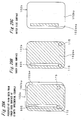
- Fig. 27A shows a sixth implemental example applied to the preferred embodiments of the present invention, and is a perspective view seen from the inner side surface of the upper second housing portion 102b of the portable radio communication apparatus.
- Fig. 27B is a plan view showing the inner side surface of the upper second housing portion 102b shown in Fig. 27A.
- Fig. 27C is a plan view showing an outer side surface of the upper second housing portion 102b shown in Fig. 27A.
- the conductor layer 102bm made of an electrically conductive material such as magnesium or zinc and including a rectangular slot 933 extending, for example, along a lower end portion of the inner side surface in parallel to a lateral or horizontal direction of the same apparatus is formed on the inner side surface of the resin housing portion 102bp (including the screw reception portions 115). This leads to constituting the upper second housing portion 102b, and then, for example, electrically connecting the antenna element 112 with the conductor layer 102bm.
- the slot 933 is formed on the inner side surface of the upper second housing portion 102b, an electrical conductor having a plurality of electric lengths can be formed on the conductor layer 102bm, and further, there can be realized the antenna element 102A that has a plurality of resonance frequencies and that can cover a plurality of frequency bands. Further, since the horizontal slot 933 is formed, a horizontally polarized radio wave can be projected from the antenna element 102A. On the other hand, since a vertically polarized radio wave is projected from the antenna element 901, polarization diversity can be constituted by using these two antenna elements.
- Fig. 28A shows a seventh implemental example applied to the preferred embodiments of the present invention, and is a perspective view seen from the inner side surface of the upper second housing portion 102b of the portable radio communication apparatus.
- Fig. 28B is a plan view showing the inner side surface of the upper second housing portion 102b shown in Fig. 28A.
- Fig. 28C is a plan view showing an outer side surface of the upper second housing portion 102b shown in Fig. 28A.
- the conductor layer 102bm made of an electrically conductive material such as magnesium or zinc and including an inverted-U-shaped rectangular slot 934, which is formed to extend, for example, along the lower end portion of the inner side surface in parallel to the lateral or horizontal direction of the same apparatus, and which has end portions extending downward is formed on the inner side surface of the resin housing portion 102bp (including the screw reception portions 115).
- the slot 934 is formed on the inner side surface of the upper second housing portion 102b, an electrical conductor having a plurality of electric lengths can be formed on the conductor layer 102bm, and further, there can be realized the antenna element 102A that has a plurality of resonance frequencies and that can cover a plurality of frequency bands. Further, by changing a formation pattern of the conductor layer 102bm, the length of the slot 934 can be adjusted so as to adjust the respective resonance frequencies.
- Fig. 29A shows an eighth implemental example applied to the preferred embodiments of the present invention, and is a perspective view seen from the inner side surface of the upper second housing portion 102b of the portable radio communication apparatus.
- Fig. 29B is a plan view showing the inner side surface of the upper second housing portion 102b shown in Fig. 29A.
- Fig. 29C is a plan view showing an outer side surface of the upper second housing portion 102b shown in Fig. 29A.
- the conductor layer 102bm made of an electrically conductive material such as magnesium or zinc and including a rectangular slot 935 extending, for example, along the end portion on the left side of the inner side surface in parallel to the vertical direction of the same apparatus is formed on the inner side surface of the resin housing portion 102bp (including the screw reception portions 115). This leads to constituting the upper second housing portion 102b, and then, for example, electrically connecting the antenna element 112 with the conductor layer 102bm.
- an electrical conductor layer 102bma extending along the end portion on the left side of the outer side surface in parallel to the vertical direction is formed on the outer side surface of the upper second housing portion 102b, and this leads to formation of a parasitic element.
- the antenna apparatus can project a radio wave through the slot 935, and further, the directivity characteristics of the antenna apparatus can be controlled using the conductor layer 102bma that serves as a parasitic element. Therefore, it is possible to project the radio wave so that the main beam thereof is directed, for example, in an opposite direction to a direction of the operator's body.
- the slot 935 is formed on the inner side surface of the upper second housing portion 102b, an electrical conductor having a plurality of electric lengths can be formed on the conductor layer 102bm, and further, there can be realized the antenna element 102A that has a plurality of resonance frequencies and that can cover a plurality of frequency bands.
- Fig. 30A shows a ninth implemental example applied to the preferred embodiments of the present invention, and is a perspective view seen from the inner side surface of the upper second housing portion 102b of the portable radio communication apparatus.
- Fig. 30B is a plan view showing the inner side surface of the upper second housing portion 102b shown in Fig. 30A.
- Fig. 30C is a plan view showing an outer side surface of the upper second housing portion 102b shown in Fig. 30A.
- rectangular electrical conductor layers 102bm1 and 120bm2 are formed on the inner side surface of the resin housing portion 102bp (including the screw reception portions 115).
- the rectangular electrical conductor layer 102bm1 made of an electrically conductive material such as magnesium or zinc is formed to extend, for example, along the end portion on the left side of the inner side surface in parallel to the vertical direction of the same apparatus.
- the rectangular electrical conductor layer 102bm2 (which is different in the longitudinal length from the rectangular electrical conductor layer 102bm1) made of an electrically conductive material such as magnesium or zinc is formed to extend, for example, along the end portion on the right side of the inner side surface in parallel to the vertical direction of the same apparatus.
- the ninth implemental example constituted as mentioned above since the two conductor layers 102bm1 and 102bm2 are formed on the inner side surface of the upper second housing 102b to serve a part of the antenna element 102A, an electrical conductor having a plurality of electric lengths can be formed on the antenna element 102A, and further, there can be realized the antenna element 102A that has a plurality of resonance frequencies and that can cover, a plurality of frequency bands. Further, by changing forming patterns of the respective conductor layers 102bm1 and 102bm2, the electric length of the antenna element 102A can be adjusted so as to adjust the respective resonance frequencies.
- the portable radio communication apparatus may be constituted to selectively switch over the antenna element of the conductor layer 102bm and that of the conductor layer 102bm2.
- the portable radio communication apparatus can be constituted to selectively switch over the two antenna elements so as to be able to attain a higher antenna gain depending on whether the portable radio communication apparatus is held in the operator's right hand or left hand.
- Fig. 31A shows a tenth implemental example applied to the fifth preferred embodiment of the present invention, and is a plan view showing that the upper housing 702 of the portable radio communication apparatus is detached.
- Fig. 31B is a side view of the portable radio communication apparatus shown in Fig. 31A.
- a resin layer 704p is formed on a front surface of the biaxial hinge portion 704 made of an electrically conductive material. Namely, by forming the resin layer 704p on the portion with which the operator's head contacts during a telephone conversation, the SAR can be reduced.
- the resin layer 704p may be formed by using a magnetic material.
- Fig. 32A is a plan view of a folding portable radio communication apparatus in a closed state thereof according to a sixth preferred embodiment of the present invention.
- Fig. 32B is a side view of the portable radio communication apparatus shown in Fig. 32A.
- Fig. 33A a plan view of the portable radio communication apparatus shown in Figs. 32A and 32B in an open state.
- Fig. 33B is a side view of the portable radio communication apparatus shown in Fig. 33A.
- the portable radio communication apparatus is different from that according to the first preferred embodiment by including an antenna element 211, instead of the antenna element 112.
- the antenna element 211 is formed to extend from the connection point 111 of the radio communication circuit 110 toward a connection point 212 on the conductor portion of the upper first housing portion 102a through the inside of the lower housing 103, the inside of the hinge portion 104, and the inside of the upper first housing portion 102a. Therefore, the connection point 111 of the radio communication circuit 110 is electrically connected with the conductor portion of the upper first housing portion 120a through the antenna element 211.
- the portable radio communication apparatus according to the sixth preferred embodiment constituted as mentioned above has the same functions and advantageous effects as those of the portable radio communication apparatus according to the first preferred embodiment.
- the antenna element 901 is formed on the inside of the boom portion 910 and the conductor portion of the upper first housing portion 120a operates as the antenna element 102A, the portable radio communication apparatus can transmit and receive radio waves without employing the external antenna as required in the conventional portable radio communication apparatus. Therefore, it is possible to prevent the external antenna from being got stuck with an operator's pocket when taking out the same apparatus from his pocket.
- the portable radio communication apparatus can be suspended from a neck of a user with a strap 910s attached to the boom portion 910 as shown in Fig. 34.
- the portable radio communication apparatus can be designed to be laterally symmetric, and further, the portable radio communication apparatus can be easily well balanced laterally or horizontally when the same apparatus is suspended from the neck of the user.
- Fig. 35A is a plan view of a folding portable radio communication apparatus in a closed state thereof according to a modified preferred embodiment of the sixth preferred embodiment of the present invention.
- Fig. 35B is a side view of the portable radio communication apparatus shown in Fig. 35A.
- the portable radio communication apparatus according to the modified preferred embodiment of the sixth preferred embodiment is different from that according to the sixth preferred embodiment, in that at least one part of the upper second housing portion 102b is made of an electrically conductive material, and in that the antenna element 211 is electrically connected with the conductor portion of the upper second housing portion 102b at the connection point 212.
- the antenna element 102A is constituted by using the antenna element 211 and the conductor portion of the upper second housing portion 102b.
- the upper first housing portion 102a may be made of either a resin material or an electrical conductive material.
- the antenna element 211 may be constituted by using a feeding line such as a coaxial cable.
- Fig. 36A is a plan view of a folding portable radio communication apparatus in an open state thereof according to a seventh preferred embodiment of the present invention.
- Fig. 36B is a side view of the portable radio communication apparatus shown in Fig. 36A.
- the portable radio communication apparatus is different from that according to the third preferred embodiment, in that the fitting intrusive circular cylindrical member 505 connected with the antenna element 504 is inserted and fitted into the circular cylindrical portion of the hinge portion 104 made of an electrically conductive material which is coupled with the upper first housing portion 102a.
- the connection point 111 of the radio communication circuit 110 is electrically connected with the conductor portion of the upper first housing portion 102a through the antenna element 504, the fitting intrusive circular cylindrical member 505, and the hinge portion 104.
- the portable radio communication apparatus according to the seventh preferred embodiment has the same functions and advantageous effects as those of the portable radio communication apparatus according to the third preferred embodiment.
- the thickness of the upper housing 102 can be made smaller and the diameter of the hinge portion 104 can be made smaller.
- the durability of the hinge portion 104 when the portable radio communication apparatus is opened or closed through the hinge portion 104 can be further improved.
- At least one part of the upper first housing portion 102a is made of an electrically conductive material.
- the present invention is not limited to this, and at least one part of the upper second housing portion 102b may be made of an electrically conductive material and the hinge portion 104 may be electrically connected with the upper second housing portion 102b.
- the antenna element 120A is constituted by using the antenna element 504, the fitting intrusive circular cylindrical member 505, the hinge portion 104, and the conductor portion of the upper second housing portion 102b. It is thereby possible to set the distance between the antenna element 102A and the human head larger during a telephone conversation, and to suppress the decrease of the antenna gain.
- the antenna element 504 may be constituted by using a feeding line such as a coaxial cable.
- Fig. 37A is a plan view of a folding portable radio communication apparatus in a closed state thereof according to an eighth preferred embodiment of the present invention.
- Fig. 37B is a side view of the portable radio communication apparatus shown in Fig. 37A.
- the portable radio communication apparatus according to the eighth preferred embodiment is different from that according to the fifth preferred embodiment shown in Fig. 17A, in that an antenna element 811 is formed to extend toward the conductor portion of the upper first housing portion 702a through the inside of the biaxial hinge portion 704, the inside of the upper second housing portion 702b, and the inside of the upper first housing portion 702a. Therefore, the connection point 801 of the radio communication circuit 110 is electrically connected with the upper first housing portion 702a at a connection point 812 through the antenna element 811.
- the portable radio communication apparatus according to the eighth preferred embodiment constituted as mentioned above has the same functions and advantageous effects as those of the portable radio communication apparatus according to the fifth preferred embodiment.
- the design quality of the portable radio communication apparatus can be further improved. Even if the structure of the biaxial hinge portion 704 is larger, the design quality of the portable radio communication apparatus can be further improved.
- the antenna element 811 can extend to be electrically insulated from the biaxial hinge portion 704, and the biaxial hinge portion 704 can operate as a parasitic element of the antenna element 102A or 901.
- the antenna element 811 is formed to extend into the upper first housing portion 702a and to be electrically connected with the conductor portion of the upper first housing portion 702a.
- the present invention is not limited to this, and the antenna element 811 may be connected with an electrical conductor portion of the biaxial hinge portion 704 connected with the conductor portion of the upper first housing portion 702a.
- the portable radio communication apparatus includes the antenna element 811.
- the present invention is not limited to this, and the portable radio communication apparatus may include the feeding line such as the coaxial cable, instead of the antenna element 811.
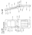
- Fig. 38A is a plan view of a folding portable radio communication apparatus in an open state thereof according to a modified preferred embodiment of the eighth preferred embodiment of the present invention.
- Fig. 38B is a side view of the portable radio communication apparatus shown in Fig. 39A.
- the portable radio communication apparatus according to the modified preferred embodiment of the eighth preferred embodiment is different from that according to the eighth preferred embodiment, in that at least one part of the upper second housing portion 102b is made of an electrically conductive material, and in that the antenna element 811 is electrically connected with the upper second housing portion 102b.
- the antenna element 102A is constituted by using the antenna element 811 and the conductor portion of the upper second housing portion 702b. It is thereby possible to set the distance between the antenna element 102A and the human head larger during a telephone conversation, and to suppress the decrease of the antenna gain.
- Fig. 39A is a plan view of a folding portable radio communication apparatus in a closed state thereof according to a ninth preferred embodiment of the present invention.
- Fig. 39B is a side view of the portable radio communication apparatus shown in Fig. 39A.
- the portable radio communication apparatus is different from the portable radio communication apparatus according to the first preferred embodiment, in that an external antenna 951 such as a quarter-wave whip antenna is provided in the vicinity of the end portion of the upper second housing portion 102b on the opposite side of the hinge portion 104 in a portable radio communication apparatus 1001, instead of the first antenna element 102A that includes the antenna element 112 and the upper first housing portion 102a.
- an external antenna 951 such as a quarter-wave whip antenna is provided in the vicinity of the end portion of the upper second housing portion 102b on the opposite side of the hinge portion 104 in a portable radio communication apparatus 1001, instead of the first antenna element 102A that includes the antenna element 112 and the upper first housing portion 102a.
- the portable radio communication apparatus constituted as mentioned above, by combining the external antenna 951 that has conventionally function as a main antenna in both closed and open states thereof, with the antenna element 901 (not shown in Figs.
- a reception diversity processing can be executed which is improved as compared with the conventional portable radio communication apparatus.
- the degree of freedom for designing the same apparatus to satisfy required antenna characteristics can be further improved, the external antenna 951 smaller in size than that of the conventional portable radio communication apparatus can be employed, and the design quality can be further improved.
- the installment position of the external antenna element 951 described in the present preferred embodiment is just one example, and the installment position of the external antenna element 951 is not limited to this.
- the external antenna 951 may be arranged in the lower housing 103.
- the boom portion 910 may be arranged in the upper housing 102.
- the folding portable radio communication apparatus has been described.
- the present invention is not limited to this, and a straight portable radio communication apparatus may be provided in which the external antenna 851 and the antenna element 901 of the boom portion 910 may be combined.
- Fig. 40A is a plan view of a folding portable radio communication apparatus in a closed state thereof according to a tenth preferred embodiment of the present invention.
- Fig. 40B is a side view of the portable radio communication apparatus shown in Fig. 40A.
- the portable radio communication apparatus is different from the portable radio communication apparatus according to the ninth preferred embodiment, in that a built-in antenna element 952 such as a ceramic chip antenna or the like is provided on the inside of the upper second housing portion 102b in the vicinity of the end portion of the upper second housing portion 102b on the opposite side of the hinge portion 104 of the portable radio communication apparatus, instead of the external antenna 951.
- the built-in antenna element 952 and the antenna element 901 of the boom portion 910 (not shown in Figs. 40A and 40B) constitute the antenna apparatus.
- Fig. 41A is a plan view of a folding portable radio communication apparatus in a closed state thereof according to a modified preferred embodiment of the tenth preferred embodiment of the present invention.
- Fig. 41B is a side view of the portable radio communication apparatus shown in Fig. 41A.
- the portable radio communication apparatus according to the modified preferred embodiment of the tenth preferred embodiment is different from the portable radio communication apparatus according to the tenth preferred embodiment, in that the built-in antenna element 952 is arranged on the inside of the lower housing 103 in the vicinity of the end portion of the lower housing 103 on the opposite side of the hinge portion 104.
- the portable radio communication apparatus according to the modified preferred embodiment of the tenth preferred embodiment has the same functions and advantageous effects as those of the portable radio communication apparatus according to the tenth preferred embodiment.
- the distance between the antenna element 901 of the boom portion 910 and the built-in antenna element 952 becomes smaller, the correlation coefficient between the antenna elements 901 and 952 becomes higher by coupling between the antenna elements 901 and 952.
- the advantageous effects such as the diversity reception may possibly be lowered. Therefore, it is preferable that the antenna elements 901 and 952 are away from each other by at least a quarter of wavelength.
- the portable radio communication apparatus includes one built-in antenna element 952 .
- the present invention is not limited to this, and the portable radio communication apparatus may include a plurality of built-in antennas. In this case, it is possible to cover a plurality of frequency bands.
- Fig. 42A is a plan view of a folding portable radio communication apparatus according to an eleventh preferred embodiment of the present invention.
- Fig. 42B is a side view of the portable radio communication apparatus shown in Fig. 42A.
- the portable radio communication apparatus according to the eleventh preferred embodiment is different from that according to the first preferred embodiment in the following points.
- the antenna element 962 is provided so as to extend from a connection point 961 (corresponding to the connection point 111 shown in Fig. 1A) that serves as a feeding point of the radio communication circuit 110 into the lower first housing portion 103a through the inside of the hinge portion 104, and one end of the antenna element 962 located on the inside of the lower first housing portion 103a is connected with a screw 963.
- the screw 963 penetrates the lower housing 103 from the outer side surface of the lower second housing portion 103b toward a screw reception portion 964 of the lower first housing portion 103b, and this leads to that the lower housing 103 is screwed with the screw 963 and the screw 963 is electrically connected with the conductor portion of the lower second housing portion 103b. Accordingly, the connection point 961 of the radio communication circuit 110 is electrically connected with the conductor portion of the lower second housing portion 103b through the antenna element 962 and the screw 963. As a result, the antenna apparatus is constituted by using the antenna element 962 and the conductor portion of the lower second housing portion 103b.
- the portable radio communication apparatus constituted as mentioned above has the same functions and advantageous effects as those of the portable radio communication apparatus according to the first preferred embodiment.
- the antenna element 962 is connected with the conductor portion of the lower second housing portion 103b.
- the present invention is not limited to this, and at least one part of the lower first housing portion 103a may be made of an electrically conductive material, and the antenna element 962 may be connected with the conductor portion of the lower first housing portion 103a.
- the conductor portion may be formed on each of the lower first housing portion 103a and the lower second housing portion 103b.
- Fig. 44A is a plan view of a slide type portable radio communication apparatus according to a twelfth preferred embodiment of the present invention.
- Fig. 44B is a side view of the portable radio communication apparatus shown in Fig. 44A.
- the portable radio communication apparatus includes an upper housing 102c, a lower housing 103c, and a sliding mechanism.
- the sliding mechanism is constituted so that two sliding protrusions 182 formed on a rear surface of the upper housing 102c are fitted into slide grooves 181 formed on both side surfaces of the lower housing 130c in a longitudinal direction thereof, respectively, and so that the upper housing 102c is slidable along the longitudinal direction thereof in a direction indicated by an arrow 183.
- a keypad 116 of the lower housing 103c appears and is made operable by the user.
- the keypad 116 of the lower housing 103c is covered with the upper housing 102c and is made inoperable by the user.
- the upper housing 102c and the lower housing 103c are integrated with each other at a minimum occupied area, and the integrated housings become similar in a form to a straight type portable radio communication apparatus which will be described later.
- a conductor layer 103cc made of an electrically conductive material is formed on a top portion of a rear surface of the lower housing 103c, and used as an antenna element 103A.
- built-in antenna elements 191 and 192 each constructed by, for example, a chip antenna are included internally in left and right end portions of a lower portion of the lower housing 103c, respectively.
- at least two of the three antenna elements 103A, 191, and 192 are formed, and transmission diversity and reception diversity are performed using the at least two antenna elements.
- Fig. 45A is a plan view of a slide type portable radio communication apparatus according to a modified preferred embodiment of the twelfth preferred embodiment of the present invention.
- Fig. 45B is a side view of the portable radio communication apparatus shown in Fig. 45A.
- the portable radio communication apparatus is characterized, as compared with that of the twelfth preferred embodiment, in that the boom portion 910 including therein the antenna element 901 connected with the connection point 902 is coupled with both edges of the upper end surface of the lower housing 103c.
- the characteristic constitutions of the portable radio communication apparatuses according to the first to eleventh preferred embodiments and their modified preferred embodiments may be applied to the slide type portable radio communication apparatuses according to the twelfth preferred embodiment and the modified preferred embodiment of the twelfth preferred embodiment.
- Fig. 46A is a plan view of a straight type portable radio communication apparatus according to the thirteenth preferred embodiment of the present invention.
- Fig. 46B is a rear view of the portable radio communication apparatus shown in Fig. 46A.
- Fig. 46C is a side view of the portable radio communication apparatus shown in Fig. 46A.
- the portable radio communication apparatus is a straight type portable radio communication apparatus which includes an upper housing 102d and a lower housing 103d that are bonded to each other.
- a conductor layer 103dc made of an electrically conductive material is formed on an upper portion of a rear surface of the lower housing 103d, and is used as the antenna element 103A.
- the built-in antenna elements 191 and 192 each constructed by, for example, a chip antenna are included in left and right end portions of a lower portion of the lower housing 103d, respectively.
- at least two of the three antenna elements 103A, 191, and 192 are formed, and transmission diversity and reception diversity are performed using the at least two antenna elements.
- Fig. 47A is a plan view of a straight type portable radio communication apparatus according to a modified preferred embodiment of the thirteenth preferred embodiment of the present invention.
- Fig. 47B is a rear view of the portable radio communication apparatus shown in Fig. 47A.
- Fig. 47C is a side view of the portable radio communication apparatus shown in Fig. 47A.
- the portable radio communication apparatus is characterized, as compared with that of the thirteenth preferred embodiment, in that the boom portion 910 including therein the antenna element 901 connected with the connection point 902 is coupled with both edges of an upper end surface of the lower housing 103d.
- the characteristic constitutions of the portable radio communication apparatuses according to the first to eleventh preferred embodiments and their modified preferred embodiments may be applied to the straight type portable radio communication apparatuses according to the thirteenth preferred embodiment and the modified preferred embodiment of the thirteenth preferred embodiment.
- the antenna or antenna element is preferably an unbalanced type antenna or antenna element.
- Fig. 43 is a longitudinal sectional view showing a detailed configuration of a boom portion 910 of a portable radio communication apparatus according to a further modified preferred embodiment of the preferred embodiments of the present invention.
- a first electrical conductor antenna element layer 911 is formed on an upper surface of the boom portion 901
- a second electrical conductor antenna element layer 912 is formed on the lower surface of the boom portion 901 to be away from the first electrical conductor antenna element layer 911. Then, the two conductor antenna element layers 911 and 912 are electrically connected with each other at a connection point 913 in the lower housing 103, and the two conductor antenna element layers 911 and 912 are also connected with the connection point 902.
- the first conductor antenna element layer 911 is formed to have an electric length at which the layer 911 resonates in a lower frequency band such as 800 MHz band or the like.
- the second conductor antenna element layer 912 is formed to have an electric length at which the layer 912 resonates in a higher frequency band such as 1.5 GHz band or the like. Then, the electric distance between the two layers 911 and 912 is smaller as the frequency becomes lower.
- the antenna gain of the conductor antenna element layer in the lower frequency band is lowered.
- the conductor portion that operates as the antenna element 102A is formed on one of the upper first housing portion 102a and the upper second housing portion 102b.
- the present invention is not limited to this, and the conductor portion that operates as the antenna element 102A may be formed on each of the upper first housing portion 102a and the upper second housing portion 102b.
- the conductor portion formed on one of the upper housing 102 and the lower housing 103 is not limited to this, and the conductor portion may be formed on each of the upper housing 102 and the lower housing 103.
- the whip antenna is employed as the external antenna.
- the present invention is not limited to this, and a fixed helical antenna may be employed.
- an inverted-F antenna may be employed as the built-in antenna.
- a plurality of antenna apparatuses may be provided in the upper housing 102.
- the upper housing 102 is connected with the lower housing 103, for example, by the antenna element 112.
- the present invention is not limited to this, and the upper housing 102 may be connected with the lower housing 103 by an electrical conductor pattern on a flexible printed wiring board.
- the boom portion 910 is made of an electrically conductive material such as magnesium or zinc, and this leads to that the mechanical strength of the boom portion 910 can be increased. Accordingly, even if the portable radio communication apparatus falls down to the ground, it is possible to prevent the same apparatus from being damaged.
- the boom portion 910 is formed to be filled with a dielectric material such as a resin material, it is advantageously possible to lower the resonance frequency of the antenna element 901 of the boom portion 910, and the portable radio communication apparatus can be made smaller in size as compared with the same apparatus in which the boom portion 910 is not filled with the dielectric material. Further, by fixing the surroundings of the antenna element 901 by a dielectric material such as a resin material, it is possible to increase the mechanical strengths of the boom portion 910 and the antenna element 901, and to improve the mass-producibility of the same apparatus.
- At least one part of the boom portion 910 may be made of an elastic or flexible resin material such as elastomer.
- the portable radio communication apparatus is put on the ground and the user pressurizes the same apparatus from above such as inadvertently stamping down the same apparatus or inadvertently dropping the same apparatus from a holding state, the impact can be absorbed and the damage of the boom portion 910 can be prevented.
- the shape of the boom portion 910 is not limited to that shown in the drawings.
- the boom portion 910 may be formed to be trapezoidal or tapered.
- at least one part of the boom portion 910 may be made of a transparent or semitransparent resin material. In this case, the design quality can be further improved.
- a light emission diode that projects light during transmission of the radio wave may be arranged in the boom portion 910.
- the folding portable radio communication apparatus As mentioned above, according to the folding portable radio communication apparatus according to the preferred embodiments, at least one part of the upper housing or lower housing is constituted to serve as the antenna element. Therefore, it is advantageously possible to increase the strength of the same apparatus against the impact such as that upon the user's dropping the same apparatus. In addition, since it is unnecessary to secure the space occupied by the antenna element, the number of parts can be decreased, and the portable radio communication apparatus can be made thinner and lighter in weight as compared with the conventional portable radio communication apparatus. Further, by allowing the hinge portion made of the electrically conductive material to function as a part of the antenna apparatus, the antenna apparatus can be made larger in size, and the antenna gain thereof can be further improved.
- the distance between the human body and the antenna apparatus can be set larger, and then, the decrease of the antenna gain caused by the electromagnetic influence of the human body can be suppressed during a telephone conversation.
- a combination of (a) a first antenna and (b) a second antenna is provided in the vicinity of the hinge portion of the lower housing of the folding portable radio communication apparatus, where (a) the first antenna is the antenna element 901 of the boom portion 910 connected at a position at which the antenna element 901 is substantially laterally symmetric relative to the width direction or the horizontal direction of the same apparatus, and (b) the second antenna includes, as the component, the upper housing or lower housing at least one part of which is made of the electrically conductive material. It is thereby possible to transmit and receive radio waves without using the conventional external antenna.
- the portable radio communication apparatus can be designed to be laterally symmetric, and the portable radio communication apparatus can be easily well balanced laterally or horizontally when the same apparatus is suspended from the neck of the user.
Priority Applications (2)
| Application Number | Priority Date | Filing Date | Title |
|---|---|---|---|
| EP10159275A EP2221912A1 (fr) | 2003-02-06 | 2004-02-02 | Appareil de communication radio portable fourni avec une pièce de boîtier fonctionnant en tant qu'antenne |
| EP10159276A EP2211422A1 (fr) | 2003-02-06 | 2004-02-02 | Appareil de communication radio portable muni d'un bras de support |
Applications Claiming Priority (4)
| Application Number | Priority Date | Filing Date | Title |
|---|---|---|---|
| JP2003029217 | 2003-02-06 | ||
| JP2003029217 | 2003-02-06 | ||
| JP2003042822 | 2003-02-20 | ||
| JP2003042822 | 2003-02-20 |
Publications (1)
| Publication Number | Publication Date |
|---|---|
| EP1445824A1 true EP1445824A1 (fr) | 2004-08-11 |
Family
ID=32658636
Family Applications (4)
| Application Number | Title | Priority Date | Filing Date |
|---|---|---|---|
| EP04002024A Withdrawn EP1445821A1 (fr) | 2003-02-06 | 2004-01-30 | Appareil de communication radio portable muni d'un bras de support |
| EP04002136A Withdrawn EP1445824A1 (fr) | 2003-02-06 | 2004-02-02 | Partie d'un boítier d'appareil de communication radio portable fonctionnant comme une antenne. |
| EP10159276A Withdrawn EP2211422A1 (fr) | 2003-02-06 | 2004-02-02 | Appareil de communication radio portable muni d'un bras de support |
| EP10159275A Withdrawn EP2221912A1 (fr) | 2003-02-06 | 2004-02-02 | Appareil de communication radio portable fourni avec une pièce de boîtier fonctionnant en tant qu'antenne |
Family Applications Before (1)
| Application Number | Title | Priority Date | Filing Date |
|---|---|---|---|
| EP04002024A Withdrawn EP1445821A1 (fr) | 2003-02-06 | 2004-01-30 | Appareil de communication radio portable muni d'un bras de support |
Family Applications After (2)
| Application Number | Title | Priority Date | Filing Date |
|---|---|---|---|
| EP10159276A Withdrawn EP2211422A1 (fr) | 2003-02-06 | 2004-02-02 | Appareil de communication radio portable muni d'un bras de support |
| EP10159275A Withdrawn EP2221912A1 (fr) | 2003-02-06 | 2004-02-02 | Appareil de communication radio portable fourni avec une pièce de boîtier fonctionnant en tant qu'antenne |
Country Status (4)
| Country | Link |
|---|---|
| US (4) | US7009567B2 (fr) |
| EP (4) | EP1445821A1 (fr) |
| KR (2) | KR100995473B1 (fr) |
| CN (3) | CN1520130B (fr) |
Cited By (4)
| Publication number | Priority date | Publication date | Assignee | Title |
|---|---|---|---|---|
| EP1739785A1 (fr) * | 2004-10-28 | 2007-01-03 | Matsushita Electric Industries Co., Ltd. | Radio portable pliable |
| WO2009020724A1 (fr) * | 2007-08-07 | 2009-02-12 | Apple Inc. | Antennes pour dispositifs électroniques portables |
| US8169373B2 (en) | 2008-09-05 | 2012-05-01 | Apple Inc. | Antennas with tuning structure for handheld devices |
| EP2221917A4 (fr) * | 2007-10-31 | 2017-03-15 | Sharp Kabushiki Kaisha | Appareil portable sans fil |
Families Citing this family (194)
| Publication number | Priority date | Publication date | Assignee | Title |
|---|---|---|---|---|
| WO2004025778A1 (fr) | 2002-09-10 | 2004-03-25 | Fractus, S.A. | Antennes multibandes couplees |
| US20050054399A1 (en) * | 2003-09-10 | 2005-03-10 | Buris Nicholas E. | Method and apparatus for providing improved antenna bandwidth |
| TWI225744B (en) * | 2003-10-06 | 2004-12-21 | Benq Corp | Flip-flop mobile phone |
| KR100703497B1 (ko) * | 2004-01-05 | 2007-04-03 | 삼성전자주식회사 | 게임 겸용 휴대용 통신 장치 |
| US9003199B2 (en) * | 2004-03-23 | 2015-04-07 | Harris Corporation | Modular cryptographic device providing multi-mode wireless LAN operation features and related methods |
| US7343183B2 (en) * | 2004-04-02 | 2008-03-11 | Matsushita Electric Industrial Co., Ltd. | Portable wireless unit |
| KR100630102B1 (ko) * | 2004-05-03 | 2006-09-27 | 삼성전자주식회사 | 슬라이딩 팝 업 타입 키패드를 구비한 휴대 통신 장치 |
| JP4444021B2 (ja) * | 2004-06-29 | 2010-03-31 | パナソニック株式会社 | 折畳式携帯無線機 |
| JP3841100B2 (ja) | 2004-07-06 | 2006-11-01 | セイコーエプソン株式会社 | 電子装置および無線通信端末 |
| JP2006050324A (ja) * | 2004-08-05 | 2006-02-16 | Matsushita Electric Ind Co Ltd | 携帯無線機 |
| JP4331072B2 (ja) | 2004-08-27 | 2009-09-16 | パナソニック株式会社 | 携帯無線機 |
| JP4636456B2 (ja) * | 2004-09-16 | 2011-02-23 | 富士通東芝モバイルコミュニケーションズ株式会社 | 無線装置 |
| US7528797B2 (en) * | 2005-08-29 | 2009-05-05 | Kyocera Wireless Corp. | Electrical connector with frequency-tuned groundplane |
| CN101053116A (zh) * | 2004-10-21 | 2007-10-10 | 三菱电机株式会社 | 滑动式便携无线电装置 |
| JP4372158B2 (ja) * | 2004-10-28 | 2009-11-25 | パナソニック株式会社 | 放送用受信機付き携帯電話 |
| JP4691958B2 (ja) * | 2004-10-29 | 2011-06-01 | 日本電気株式会社 | 携帯無線端末 |
| JP2006129386A (ja) * | 2004-11-01 | 2006-05-18 | Fujitsu Ltd | アンテナ装置及び無線通信装置 |
| KR101050634B1 (ko) * | 2004-11-10 | 2011-07-19 | 삼성전자주식회사 | 휴대용 단말기의 안테나 장치 |
| JP4300210B2 (ja) * | 2004-11-18 | 2009-07-22 | 株式会社カシオ日立モバイルコミュニケーションズ | 携帯型無線機 |
| JP4197684B2 (ja) * | 2005-03-23 | 2008-12-17 | 株式会社東芝 | 携帯無線機 |
| JP4826880B2 (ja) * | 2005-04-12 | 2011-11-30 | 日本電気株式会社 | 折り畳み型携帯電話機 |
| US7447528B2 (en) * | 2005-04-12 | 2008-11-04 | Nokia Corporation | Multifunction electronic device |
| TWI257739B (en) * | 2005-05-26 | 2006-07-01 | Wistron Neweb Corp | Mobile communication device |
| US20070003088A1 (en) * | 2005-06-27 | 2007-01-04 | Nokia Corporation | Hearing aid compatible mobile phone and method |
| US20070021161A1 (en) * | 2005-07-19 | 2007-01-25 | Nokia Corporation | Hand-portable radio communications device comprising relatively movable first and second portions |
| EP1911124A1 (fr) | 2005-07-21 | 2008-04-16 | Fractus, S.A. | Dispositif portatif avec deux antennes et procédé d'amélioration de l'isolement entre les antennes |
| EP1973195A4 (fr) * | 2006-01-12 | 2010-06-09 | Nec Corp | Dispositif terminal mobile, procede de commutation d'antennes et programme |
| US7519328B2 (en) | 2006-01-19 | 2009-04-14 | Murata Manufacturing Co., Ltd. | Wireless IC device and component for wireless IC device |
| JP4998463B2 (ja) | 2006-04-10 | 2012-08-15 | 株式会社村田製作所 | 無線icデバイス |
| CN102780084B (zh) * | 2006-04-14 | 2016-03-02 | 株式会社村田制作所 | 天线 |
| EP2009736B1 (fr) | 2006-04-14 | 2016-01-13 | Murata Manufacturing Co. Ltd. | Composant a circuit integre sans fil |
| CN101416350B (zh) * | 2006-04-26 | 2013-09-04 | 株式会社村田制作所 | 带馈电电路板的物件 |
| US9064198B2 (en) | 2006-04-26 | 2015-06-23 | Murata Manufacturing Co., Ltd. | Electromagnetic-coupling-module-attached article |
| CN101454992B (zh) | 2006-05-26 | 2015-07-15 | 株式会社村田制作所 | 数据耦合器 |
| JPWO2007138836A1 (ja) * | 2006-05-30 | 2009-10-01 | 株式会社村田製作所 | 情報端末機器 |
| WO2007138682A1 (fr) * | 2006-05-30 | 2007-12-06 | Panasonic Corporation | Unité sans fil portable |
| CN101460964B (zh) | 2006-06-01 | 2011-09-21 | 株式会社村田制作所 | 无线ic器件和无线ic器件用复合元件 |
| WO2007145053A1 (fr) * | 2006-06-12 | 2007-12-21 | Murata Manufacturing Co., Ltd. | Module couplé au plan électromagnétique, système d'inspection de dispositif à ci sans fil, module couplé au plan électromagnétique utilisant le système et procédé de fabrication de dispositif à ci sans fil |
| WO2008001561A1 (fr) | 2006-06-30 | 2008-01-03 | Murata Manufacturing Co., Ltd. | Disque optique |
| JP4691595B2 (ja) * | 2006-07-06 | 2011-06-01 | シャープ株式会社 | 無線機 |
| WO2008007606A1 (fr) * | 2006-07-11 | 2008-01-17 | Murata Manufacturing Co., Ltd. | Dispositif à antenne et circuit résonnant |
| JP4310589B2 (ja) | 2006-08-24 | 2009-08-12 | 株式会社村田製作所 | 無線icデバイスの検査システム及びそれを用いた無線icデバイスの製造方法 |
| JP2008072382A (ja) * | 2006-09-13 | 2008-03-27 | Toshiba Corp | アンテナ装置及び無線装置 |
| DE112007002024B4 (de) | 2006-09-26 | 2010-06-10 | Murata Mfg. Co., Ltd., Nagaokakyo-shi | Induktiv gekoppeltes Modul und Element mit induktiv gekoppeltem Modul |
| KR100800756B1 (ko) * | 2006-10-04 | 2008-02-01 | 삼성전자주식회사 | 휴대단말기의 디지털멀티미디어 방송신호 수신 장치 |
| US20080100514A1 (en) * | 2006-10-25 | 2008-05-01 | Abdul-Gaffoor Mohammed R | Antenna Arrangement for Hinged Wireless Communication Device |
| JP4798223B2 (ja) * | 2006-10-27 | 2011-10-19 | 株式会社村田製作所 | 電磁結合モジュール付き物品 |
| US7639795B2 (en) * | 2006-12-19 | 2009-12-29 | Kyocera Corporation | Hinge device and method for wireless communication device |
| JP4819666B2 (ja) * | 2006-12-25 | 2011-11-24 | 富士通株式会社 | 無線機器 |
| WO2008090943A1 (fr) | 2007-01-26 | 2008-07-31 | Murata Manufacturing Co., Ltd. | Conteneur avec module à couplage électromagnétique |
| WO2008096576A1 (fr) | 2007-02-06 | 2008-08-14 | Murata Manufacturing Co., Ltd. | Matériau d'emballage pourvu d'un module couplé de façon électromagnétique |
| WO2008096574A1 (fr) * | 2007-02-06 | 2008-08-14 | Murata Manufacturing Co., Ltd. | Matériau d'emballage pourvu d'un module couplé de façon électromagnétique |
| ATE555453T1 (de) | 2007-04-06 | 2012-05-15 | Murata Manufacturing Co | Funk-ic-vorrichtung |
| US8009101B2 (en) | 2007-04-06 | 2011-08-30 | Murata Manufacturing Co., Ltd. | Wireless IC device |
| JP4697332B2 (ja) * | 2007-04-09 | 2011-06-08 | 株式会社村田製作所 | 無線icデバイス |
| US8235299B2 (en) | 2007-07-04 | 2012-08-07 | Murata Manufacturing Co., Ltd. | Wireless IC device and component for wireless IC device |
| US7762472B2 (en) | 2007-07-04 | 2010-07-27 | Murata Manufacturing Co., Ltd | Wireless IC device |
| JP5079378B2 (ja) * | 2007-04-16 | 2012-11-21 | 日本写真印刷株式会社 | 携帯機器 |
| JP4930586B2 (ja) | 2007-04-26 | 2012-05-16 | 株式会社村田製作所 | 無線icデバイス |
| ATE544129T1 (de) | 2007-04-27 | 2012-02-15 | Murata Manufacturing Co | Drahtlose ic-vorrichtung |
| EP2141769A4 (fr) | 2007-04-27 | 2010-08-11 | Murata Manufacturing Co | Dispositif sans fil à circuit intégré |
| DE112008000065B4 (de) | 2007-05-10 | 2011-07-07 | Murata Manufacturing Co., Ltd., Kyoto-fu | Drahtloses IC-Bauelement |
| EP2148449B1 (fr) | 2007-05-11 | 2012-12-12 | Murata Manufacturing Co., Ltd. | Dispositif ic sans fil |
| ATE545174T1 (de) * | 2007-06-27 | 2012-02-15 | Murata Manufacturing Co | Kabelloses ic-gerät |
| US8060162B2 (en) * | 2007-06-27 | 2011-11-15 | Motorola Mobility, Inc. | Slider grounding to mitigate unwanted coupling and lossy antenna resonance |
| CN104078767B (zh) * | 2007-07-09 | 2015-12-09 | 株式会社村田制作所 | 无线ic器件 |
| EP2166490B1 (fr) * | 2007-07-17 | 2015-04-01 | Murata Manufacturing Co. Ltd. | Dispositif ci sans fil et appareil électronique |
| US20090021352A1 (en) * | 2007-07-18 | 2009-01-22 | Murata Manufacturing Co., Ltd. | Radio frequency ic device and electronic apparatus |
| ATE556466T1 (de) * | 2007-07-18 | 2012-05-15 | Murata Manufacturing Co | Drahtloses ic-gerät |
| WO2009011375A1 (fr) | 2007-07-18 | 2009-01-22 | Murata Manufacturing Co., Ltd. | Dispositif à circuit intégré sans fil et son procédé de fabrication |
| JP5104865B2 (ja) | 2007-07-18 | 2012-12-19 | 株式会社村田製作所 | 無線icデバイス |
| US7830311B2 (en) | 2007-07-18 | 2010-11-09 | Murata Manufacturing Co., Ltd. | Wireless IC device and electronic device |
| JP4900106B2 (ja) * | 2007-07-19 | 2012-03-21 | 富士通株式会社 | シール構造、電子装置、携帯装置及び電子装置の製造方法 |
| JP2009065388A (ja) * | 2007-09-05 | 2009-03-26 | Toshiba Corp | 無線装置及びアンテナ装置 |
| US20090061966A1 (en) * | 2007-09-05 | 2009-03-05 | Motorola, Inc. | Antenna and speaker assembly |
| JP4894740B2 (ja) * | 2007-12-03 | 2012-03-14 | 日本電気株式会社 | 携帯無線機及び無線通信方法 |
| KR101047189B1 (ko) | 2007-12-20 | 2011-07-06 | 가부시키가이샤 무라타 세이사쿠쇼 | 무선 ic 디바이스 |
| EP2207240B1 (fr) | 2007-12-26 | 2013-08-21 | Murata Manufacturing Co., Ltd. | Appareil d'antenne et dispositif ci sans fil |
| FI20075974A0 (fi) * | 2007-12-28 | 2007-12-28 | Nokia Corp | Laite ja menetelmä |
| US8264412B2 (en) | 2008-01-04 | 2012-09-11 | Apple Inc. | Antennas and antenna carrier structures for electronic devices |
| JP2009165082A (ja) * | 2008-01-10 | 2009-07-23 | Panasonic Corp | 携帯無線機 |
| WO2009110382A1 (fr) * | 2008-03-03 | 2009-09-11 | 株式会社村田製作所 | Antenne composite |
| JP5267463B2 (ja) | 2008-03-03 | 2013-08-21 | 株式会社村田製作所 | 無線icデバイス及び無線通信システム |
| US20110001685A1 (en) * | 2008-03-11 | 2011-01-06 | Mitsubishi Cable Industries, Ltd. | Antenna device and method for producing the same |
| WO2009119548A1 (fr) * | 2008-03-26 | 2009-10-01 | 株式会社村田製作所 | Dispositif radio à circuit intégré |
| US7933123B2 (en) | 2008-04-11 | 2011-04-26 | Apple Inc. | Portable electronic device with two-piece housing |
| JP4535209B2 (ja) * | 2008-04-14 | 2010-09-01 | 株式会社村田製作所 | 無線icデバイス、電子機器及び無線icデバイスの共振周波数の調整方法 |
| WO2009130748A1 (fr) * | 2008-04-25 | 2009-10-29 | パナソニック株式会社 | Dispositif radio mobile |
| JPWO2009139100A1 (ja) * | 2008-05-14 | 2011-09-15 | パナソニック株式会社 | 携帯無線機 |
| EP2284949B1 (fr) | 2008-05-21 | 2016-08-03 | Murata Manufacturing Co. Ltd. | Dispositif ci sans fil |
| WO2009142068A1 (fr) * | 2008-05-22 | 2009-11-26 | 株式会社村田製作所 | Dispositif à circuit intégré sans fil et son procédé de fabrication |
| JP5218558B2 (ja) | 2008-05-26 | 2013-06-26 | 株式会社村田製作所 | 無線icデバイスシステム及び無線icデバイスの真贋判定方法 |
| CN102047500B (zh) * | 2008-05-28 | 2014-05-28 | 株式会社村田制作所 | 无线ic器件用部件及无线ic器件 |
| CN102017289B (zh) * | 2008-06-19 | 2014-06-25 | 夏普株式会社 | 无线装置 |
| CN101983457B (zh) * | 2008-06-19 | 2014-02-05 | 夏普株式会社 | 无线装置 |
| JP4557186B2 (ja) * | 2008-06-25 | 2010-10-06 | 株式会社村田製作所 | 無線icデバイスとその製造方法 |
| EP2306586B1 (fr) * | 2008-07-04 | 2014-04-02 | Murata Manufacturing Co. Ltd. | Dispositif à circuit intégré sans fil |
| US8311599B2 (en) * | 2008-07-17 | 2012-11-13 | Sharp Kabushiki Kaisha | Short-side direction slide type radio apparatus |
| JP5434920B2 (ja) * | 2008-08-19 | 2014-03-05 | 株式会社村田製作所 | 無線icデバイス及びその製造方法 |
| US20100087235A1 (en) * | 2008-10-08 | 2010-04-08 | Chi-Ming Chiang | Loop antenna for cell phone having a metallic or non-metallic casing |
| WO2010047214A1 (fr) * | 2008-10-24 | 2010-04-29 | 株式会社村田製作所 | Dispositif ci radio |
| CN102197537B (zh) * | 2008-10-29 | 2014-06-18 | 株式会社村田制作所 | 无线ic器件 |
| CN104362424B (zh) * | 2008-11-17 | 2018-09-21 | 株式会社村田制作所 | 无线通信设备 |
| JP5027784B2 (ja) * | 2008-11-26 | 2012-09-19 | 京セラ株式会社 | 携帯電子機器 |
| JP5222716B2 (ja) * | 2008-12-25 | 2013-06-26 | 京セラ株式会社 | 携帯端末 |
| CN103500873B (zh) | 2009-01-09 | 2016-08-31 | 株式会社村田制作所 | 无线ic器件及无线ic模块 |
| WO2010082413A1 (fr) * | 2009-01-16 | 2010-07-22 | 株式会社村田製作所 | Dispositif haute fréquence et dispositif ci sans fil |
| EP2385580B1 (fr) | 2009-01-30 | 2014-04-09 | Murata Manufacturing Co., Ltd. | Antenne et dispositif de circuit intégré sans fil |
| WO2010095200A1 (fr) * | 2009-02-18 | 2010-08-26 | パナソニック株式会社 | Récepteur |
| JP5510450B2 (ja) | 2009-04-14 | 2014-06-04 | 株式会社村田製作所 | 無線icデバイス |
| CN103022661B (zh) | 2009-04-21 | 2014-12-03 | 株式会社村田制作所 | 电子设备及天线装置的谐振频率设定方法 |
| KR101544373B1 (ko) * | 2009-05-18 | 2015-08-17 | 삼성전자주식회사 | 다수개의 안테나들을 구비하는 통신 단말기 및 그의 통신 시스템 접속 방법 |
| WO2010140429A1 (fr) | 2009-06-03 | 2010-12-09 | 株式会社村田製作所 | Dispositif de circuit intégré sans fil et son procédé de production |
| KR20100133536A (ko) * | 2009-06-12 | 2010-12-22 | 삼성전자주식회사 | 폴더 타입 휴대용 단말기의 내장형 안테나 장치 |
| JP5516580B2 (ja) | 2009-06-19 | 2014-06-11 | 株式会社村田製作所 | 無線icデバイス及び給電回路と放射板との結合方法 |
| WO2011001709A1 (fr) | 2009-07-03 | 2011-01-06 | 株式会社村田製作所 | Antenne et module d'antenne |
| JP5182431B2 (ja) | 2009-09-28 | 2013-04-17 | 株式会社村田製作所 | 無線icデバイスおよびそれを用いた環境状態検出方法 |
| JP5201270B2 (ja) | 2009-09-30 | 2013-06-05 | 株式会社村田製作所 | 回路基板及びその製造方法 |
| JP5304580B2 (ja) | 2009-10-02 | 2013-10-02 | 株式会社村田製作所 | 無線icデバイス |
| CN102576939B (zh) | 2009-10-16 | 2015-11-25 | 株式会社村田制作所 | 天线及无线ic器件 |
| CN102598413A (zh) | 2009-10-27 | 2012-07-18 | 株式会社村田制作所 | 收发装置及无线标签读取装置 |
| CN102473244B (zh) | 2009-11-04 | 2014-10-08 | 株式会社村田制作所 | 无线ic标签、读写器及信息处理系统 |
| CN102549838B (zh) | 2009-11-04 | 2015-02-04 | 株式会社村田制作所 | 通信终端及信息处理系统 |
| WO2011055701A1 (fr) | 2009-11-04 | 2011-05-12 | 株式会社村田製作所 | Terminal de communication et système de traitement de l'information |
| CN102576929B (zh) | 2009-11-20 | 2015-01-28 | 株式会社村田制作所 | 天线装置以及移动通信终端 |
| JP2011120071A (ja) * | 2009-12-04 | 2011-06-16 | Panasonic Corp | 携帯無線機 |
| GB2488450B (en) | 2009-12-24 | 2014-08-20 | Murata Manufacturing Co | Antenna and mobile terminal |
| JP5758648B2 (ja) * | 2010-02-24 | 2015-08-05 | 京セラ株式会社 | 携帯端末 |
| WO2011108340A1 (fr) | 2010-03-03 | 2011-09-09 | 株式会社村田製作所 | Module de communication sans fil et dispositif de communication sans fil |
| CN102782937B (zh) | 2010-03-03 | 2016-02-17 | 株式会社村田制作所 | 无线通信器件及无线通信终端 |
| CN102576940B (zh) | 2010-03-12 | 2016-05-04 | 株式会社村田制作所 | 无线通信器件及金属制物品 |
| CN102195132A (zh) * | 2010-03-17 | 2011-09-21 | 深圳富泰宏精密工业有限公司 | 无线通信装置 |
| WO2011118379A1 (fr) | 2010-03-24 | 2011-09-29 | 株式会社村田製作所 | Système d'identification par radiofréquence |
| JP2011217184A (ja) * | 2010-03-31 | 2011-10-27 | Fujitsu Toshiba Mobile Communications Ltd | 携帯無線装置 |
| WO2011122163A1 (fr) | 2010-03-31 | 2011-10-06 | 株式会社村田製作所 | Antenne et dispositif de communication sans fil |
| CN102244314B (zh) * | 2010-05-10 | 2013-11-27 | 赖文正 | 磁性天线配置机构 |
| JP5299351B2 (ja) | 2010-05-14 | 2013-09-25 | 株式会社村田製作所 | 無線icデバイス |
| JP5170156B2 (ja) | 2010-05-14 | 2013-03-27 | 株式会社村田製作所 | 無線icデバイス |
| JP2012015976A (ja) * | 2010-07-05 | 2012-01-19 | Panasonic Corp | 携帯無線機 |
| JP5376060B2 (ja) | 2010-07-08 | 2013-12-25 | 株式会社村田製作所 | アンテナ及びrfidデバイス |
| CN102859790B (zh) | 2010-07-28 | 2015-04-01 | 株式会社村田制作所 | 天线装置及通信终端设备 |
| JP5423897B2 (ja) | 2010-08-10 | 2014-02-19 | 株式会社村田製作所 | プリント配線板及び無線通信システム |
| US8923528B2 (en) | 2010-08-30 | 2014-12-30 | Microsoft Corporation | Hearing aid-compatible apparatus for wireless communication devices |
| JP5234071B2 (ja) | 2010-09-03 | 2013-07-10 | 株式会社村田製作所 | Rficモジュール |
| WO2012041213A1 (fr) * | 2010-09-30 | 2012-04-05 | 联想(北京)有限公司 | Dispositif électronique |
| WO2012043432A1 (fr) | 2010-09-30 | 2012-04-05 | 株式会社村田製作所 | Dispositif à circuit intégré sans fil |
| WO2012050037A1 (fr) | 2010-10-12 | 2012-04-19 | 株式会社村田製作所 | Appareil de type antenne et appareil de type terminal de communication |
| GB2501385B (en) | 2010-10-21 | 2015-05-27 | Murata Manufacturing Co | Communication terminal device |
| JP5619565B2 (ja) * | 2010-10-27 | 2014-11-05 | 京セラ株式会社 | 通信装置 |
| JP5682238B2 (ja) * | 2010-11-05 | 2015-03-11 | 富士通株式会社 | スライド式無線端末装置 |
| JP5510560B2 (ja) | 2011-01-05 | 2014-06-04 | 株式会社村田製作所 | 無線通信デバイス |
| WO2012096365A1 (fr) | 2011-01-14 | 2012-07-19 | 株式会社村田製作所 | Boîtier de puce rfid et étiquette rfid |
| JP5370616B2 (ja) | 2011-02-28 | 2013-12-18 | 株式会社村田製作所 | 無線通信デバイス |
| JP5630566B2 (ja) | 2011-03-08 | 2014-11-26 | 株式会社村田製作所 | アンテナ装置及び通信端末機器 |
| CN103081221B (zh) | 2011-04-05 | 2016-06-08 | 株式会社村田制作所 | 无线通信器件 |
| WO2012141070A1 (fr) | 2011-04-13 | 2012-10-18 | 株式会社村田製作所 | Dispositif à circuit intégré sans fil et terminal de communication sans fil |
| JP5741200B2 (ja) * | 2011-05-11 | 2015-07-01 | 富士通株式会社 | 通信装置 |
| JP5569648B2 (ja) | 2011-05-16 | 2014-08-13 | 株式会社村田製作所 | 無線icデバイス |
| JP5488767B2 (ja) | 2011-07-14 | 2014-05-14 | 株式会社村田製作所 | 無線通信デバイス |
| CN103370886B (zh) | 2011-07-15 | 2015-05-20 | 株式会社村田制作所 | 无线通信器件 |
| WO2013011865A1 (fr) | 2011-07-19 | 2013-01-24 | 株式会社村田製作所 | Module d'antenne, dispositif d'antenne, étiquette rfid et dispositif terminal de communication |
| US9002283B2 (en) | 2011-08-01 | 2015-04-07 | Apple Inc. | Antenna switching system with adaptive switching criteria |
| JP5418737B2 (ja) | 2011-09-09 | 2014-02-19 | 株式会社村田製作所 | アンテナ装置および無線デバイス |
| US8639194B2 (en) * | 2011-09-28 | 2014-01-28 | Motorola Mobility Llc | Tunable antenna with a conductive, physical component co-located with the antenna |
| WO2013080991A1 (fr) | 2011-12-01 | 2013-06-06 | 株式会社村田製作所 | Dispositif ci sans fil et son procédé de fabrication |
| JP5354137B1 (ja) | 2012-01-30 | 2013-11-27 | 株式会社村田製作所 | 無線icデバイス |
| JP5464307B2 (ja) | 2012-02-24 | 2014-04-09 | 株式会社村田製作所 | アンテナ装置および無線通信装置 |
| US20130241800A1 (en) * | 2012-03-14 | 2013-09-19 | Robert W. Schlub | Electronic Device with Tunable and Fixed Antennas |
| WO2013153697A1 (fr) | 2012-04-13 | 2013-10-17 | 株式会社村田製作所 | Procédé d'inspection d'étiquette d'identification par radiofréquence (rfid) et dispositif d'inspection |
| US9122446B2 (en) * | 2012-05-30 | 2015-09-01 | Apple Inc. | Antenna structures in electronic devices with hinged enclosures |
| KR101393829B1 (ko) * | 2012-10-04 | 2014-05-12 | 엘지이노텍 주식회사 | 통신 단말기, 그의 안테나 장치 및 그의 동작 방법 |
| JP5907479B2 (ja) * | 2013-03-22 | 2016-04-26 | カシオ計算機株式会社 | アンテナ装置及び電子機器 |
| US9680202B2 (en) | 2013-06-05 | 2017-06-13 | Apple Inc. | Electronic devices with antenna windows on opposing housing surfaces |
| KR20150004521A (ko) * | 2013-07-03 | 2015-01-13 | 삼성전자주식회사 | 안테나 장치를 구비하는 휴대 전자 기기 |
| KR101544698B1 (ko) | 2013-12-23 | 2015-08-17 | 주식회사 이엠따블유 | 내장형 안테나 |
| US9450289B2 (en) | 2014-03-10 | 2016-09-20 | Apple Inc. | Electronic device with dual clutch barrel cavity antennas |
| KR102177285B1 (ko) | 2014-09-01 | 2020-11-10 | 삼성전자주식회사 | 안테나 장치 및 그것을 포함하는 전자 장치 |
| CN105655703B (zh) * | 2014-11-25 | 2018-12-14 | 联想(北京)有限公司 | 一种天线和电子设备 |
| US9653777B2 (en) | 2015-03-06 | 2017-05-16 | Apple Inc. | Electronic device with isolated cavity antennas |
| US10268236B2 (en) | 2016-01-27 | 2019-04-23 | Apple Inc. | Electronic devices having ventilation systems with antennas |
| US10446911B2 (en) * | 2016-02-08 | 2019-10-15 | Microsoft Technology Licensing, Llc | Cover of device acting as antenna of the device |
| KR102433402B1 (ko) * | 2016-02-19 | 2022-08-17 | 삼성전자주식회사 | 안테나 및 이를 포함하는 전자 장치 |
| KR102518499B1 (ko) * | 2016-04-22 | 2023-04-05 | 삼성전자주식회사 | 안테나 및 이를 포함하는 전자 장치 |
| CN106100686B (zh) * | 2016-05-25 | 2019-03-12 | 广州三星通信技术研究有限公司 | 电子终端 |
| KR102501935B1 (ko) * | 2016-08-31 | 2023-02-21 | 삼성전자 주식회사 | 안테나 장치 및 이를 포함하는 전자 기기 |
| DE102017200129A1 (de) * | 2017-01-05 | 2018-07-05 | Fraunhofer-Gesellschaft zur Förderung der angewandten Forschung e.V. | Ndip-Antenne |
| CN114142216A (zh) | 2017-03-06 | 2022-03-04 | 斯纳普公司 | 可穿戴设备天线系统 |
| CN110582893B (zh) | 2017-04-28 | 2021-07-09 | 小岛优 | 天线装置及便携式终端 |
| CN109494477B (zh) * | 2017-09-12 | 2022-01-07 | 中兴通讯股份有限公司 | 设备天线及可折叠设备 |
| GB2571279B (en) | 2018-02-21 | 2022-03-09 | Pet Tech Limited | Antenna arrangement and associated method |
| US11239550B2 (en) * | 2020-04-15 | 2022-02-01 | Apple Inc. | Electronic devices having compact ultra-wideband antennas |
| US11715872B2 (en) * | 2020-06-25 | 2023-08-01 | Getac Technology Corporation | Electronic device and pivotable assembly |
| EP4191372A4 (fr) | 2020-11-06 | 2024-01-10 | Samsung Electronics Co Ltd | Dispositif électronique comprenant un affichage flexible et une antenne |
| CN113533525A (zh) * | 2021-08-24 | 2021-10-22 | 山东省科学院激光研究所 | 基于激光超声及振镜协同的金属增材同步检测系统及方法 |
Citations (7)
| Publication number | Priority date | Publication date | Assignee | Title |
|---|---|---|---|---|
| US4992799A (en) * | 1989-09-28 | 1991-02-12 | Motorola, Inc. | Adaptable antenna |
| US5649306A (en) * | 1994-09-16 | 1997-07-15 | Motorola, Inc. | Portable radio housing incorporating diversity antenna structure |
| WO1999004500A1 (fr) * | 1997-07-16 | 1999-01-28 | Siemens Aktiengesellschaft | Radiotelephone portatif |
| US5903821A (en) * | 1995-07-13 | 1999-05-11 | Sony Corporation | Portable telephone with microstrip antennas |
| US6272356B1 (en) * | 1999-05-10 | 2001-08-07 | Ericsson Inc. | Mechanical spring antenna and radiotelephones incorporating same |
| US6307520B1 (en) * | 2000-07-25 | 2001-10-23 | International Business Machines Corporation | Boxed-in slot antenna with space-saving configuration |
| US6340952B1 (en) * | 2000-10-20 | 2002-01-22 | Hon Hai Precision Ind. Co., Ltd. | Induced loop antenna |
Family Cites Families (50)
| Publication number | Priority date | Publication date | Assignee | Title |
|---|---|---|---|---|
| US4313119A (en) * | 1980-04-18 | 1982-01-26 | Motorola, Inc. | Dual mode transceiver antenna |
| US4471493A (en) | 1982-12-16 | 1984-09-11 | Gte Automatic Electric Inc. | Wireless telephone extension unit with self-contained dipole antenna |
| JPS6433248A (en) | 1987-07-23 | 1989-02-03 | Toyo Boseki | Production of raised warp knitted fabric |
| JPH0631798Y2 (ja) | 1987-08-22 | 1994-08-22 | 松下電器産業株式会社 | 携帯型コ−ドレス電話器 |
| US5246374A (en) * | 1992-05-19 | 1993-09-21 | Alma Boodram | Expandable family tree and modular kit for building the same |
| JPH06216621A (ja) | 1993-01-18 | 1994-08-05 | Fujitsu Ltd | 内蔵アンテナ |
| US5561437A (en) | 1994-09-15 | 1996-10-01 | Motorola, Inc. | Two position fold-over dipole antenna |
| JP3574863B2 (ja) * | 1995-05-17 | 2004-10-06 | 株式会社日立国際電気 | 携帯電話機 |
| JPH0964778A (ja) | 1995-08-25 | 1997-03-07 | Nec Corp | 携帯電話機構造 |
| JP2000500315A (ja) * | 1995-11-15 | 2000-01-11 | アルゴン・アーベー | 携帯無線通信機用小型アンテナ及びそのスイッチレスアンテナ接続手段 |
| US5760747A (en) * | 1996-03-04 | 1998-06-02 | Motorola, Inc. | Energy diversity antenna |
| JP3192085B2 (ja) * | 1996-03-13 | 2001-07-23 | 株式会社日立国際電気 | 小形アンテナ |
| JPH1064648A (ja) * | 1996-08-22 | 1998-03-06 | Casio Comput Co Ltd | アンテナ用ヒンジ型コネクタ及び該コネクタを使用した無線通信機器 |
| JPH1065567A (ja) * | 1996-08-26 | 1998-03-06 | Matsushita Electric Ind Co Ltd | 無線通信装置 |
| JP3767030B2 (ja) | 1996-09-09 | 2006-04-19 | 三菱電機株式会社 | 折畳式無線通信装置 |
| SE511131C2 (sv) * | 1997-11-06 | 1999-08-09 | Ericsson Telefon Ab L M | Portabel elektronisk kommunikationsanordning med flerbandigt antennsystem |
| US5991643A (en) * | 1997-11-28 | 1999-11-23 | Acer Peripherals, Inc. | Radio transceiver having switchable antennas |
| US5995052A (en) | 1998-05-15 | 1999-11-30 | Ericsson Inc. | Flip open antenna for a communication device |
| SE514773C2 (sv) * | 1998-09-28 | 2001-04-23 | Allgon Ab | Radiokommunikationsenhet och antennsystem |
| GB2344969B (en) * | 1998-12-19 | 2003-02-26 | Nec Technologies | Mobile phone with incorporated antenna |
| JP3538134B2 (ja) | 1999-09-14 | 2004-06-14 | 埼玉日本電気株式会社 | 携帯電話機 |
| EP1087461B1 (fr) * | 1999-09-21 | 2013-02-27 | Alcatel Lucent | Equipement radio mobile avec antenne de culasse |
| US6255996B1 (en) * | 1999-12-02 | 2001-07-03 | Qualcomm Incorporated | Efficient antenna system for a personal communication device |
| DE10051870A1 (de) * | 1999-12-08 | 2001-07-12 | Busch Dieter & Co Prueftech | Ergonomisch gestaltete, störsignalreduzierende Lagemesssonde zum gegenseitigen Ausrichten von Körpern |
| JP3546784B2 (ja) * | 1999-12-14 | 2004-07-28 | 日本電気株式会社 | 携帯端末 |
| JP2001284933A (ja) * | 2000-03-28 | 2001-10-12 | Kyocera Corp | 携帯無線機 |
| GB2364176A (en) * | 2000-06-30 | 2002-01-16 | Nokia Mobile Phones Ltd | Multi-mode antenna |
| JP2002027066A (ja) * | 2000-07-06 | 2002-01-25 | Nec Saitama Ltd | 折り畳み形携帯無線機 |
| US6625469B1 (en) * | 2000-08-09 | 2003-09-23 | Motorola, Inc. | Upper support assembly for a wireless communication device |
| JP2002084355A (ja) | 2000-09-06 | 2002-03-22 | Nec Saitama Ltd | 携帯端末装置 |
| US6885880B1 (en) * | 2000-09-22 | 2005-04-26 | Teleponaktiebolaget Lm Ericsson (Publ.) | Inverted-F antenna for flip-style mobile terminals |
| AU2002213017A1 (en) | 2000-10-10 | 2002-04-22 | Motorola Inc., A Corporation Of The State Of Delaware | Data entry device |
| DE10053817A1 (de) | 2000-10-30 | 2002-05-02 | Soft Edv Gmbh H | Anordnung zur drahtlosen Informationsübertragung |
| JP2002185229A (ja) * | 2000-12-11 | 2002-06-28 | Toshiba Corp | 移動通信端末とそのアンテナ実装構造 |
| JP4120755B2 (ja) | 2001-03-30 | 2008-07-16 | 日本電気株式会社 | 携帯電話装置用アンテナのアース構造 |
| JP3830773B2 (ja) | 2001-05-08 | 2006-10-11 | 三菱電機株式会社 | 携帯電話機 |
| US7096046B2 (en) * | 2001-07-17 | 2006-08-22 | Wildseed Ltd. | Luminescent and illumination signaling displays utilizing a mobile communication device with laser |
| EP1414105A1 (fr) * | 2001-07-30 | 2004-04-28 | Mitsubishi Denki Kabushiki Kaisha | Commutateur d'antennes et appareil portable |
| KR20030061072A (ko) * | 2002-01-10 | 2003-07-18 | 주식회사 어필텔레콤 | 휴대폰 안테나 |
| KR100593984B1 (ko) * | 2002-01-18 | 2006-06-30 | 삼성전자주식회사 | 힌지 스프링을 이용한 안테나 장치 |
| US7180451B2 (en) * | 2002-01-22 | 2007-02-20 | Gps Industries, Inc. | Endurable sports PDA with communications capabilities and accessories therefor |
| US6765536B2 (en) * | 2002-05-09 | 2004-07-20 | Motorola, Inc. | Antenna with variably tuned parasitic element |
| CN1543713B (zh) * | 2002-06-03 | 2010-05-12 | 索尼爱立信移动通信日本株式会社 | 便携式无线终端 |
| US6697022B2 (en) * | 2002-06-19 | 2004-02-24 | Motorola, Inc. | Antenna element incorporated in hinge mechanism |
| KR100998409B1 (ko) * | 2002-07-31 | 2010-12-03 | 파나소닉 주식회사 | 휴대형 무선 통신 장치 |
| JP2004104419A (ja) * | 2002-09-09 | 2004-04-02 | Hitachi Cable Ltd | 携帯無線機用アンテナ |
| US6819295B1 (en) * | 2003-02-13 | 2004-11-16 | Sheng Yeng Peng | Dual frequency anti-jamming antenna |
| US6861989B2 (en) * | 2003-07-03 | 2005-03-01 | Motorola, Inc. | Antenna system for a communication device |
| US7392069B2 (en) * | 2004-02-19 | 2008-06-24 | Nokia Corporation | Handle for a mobile station and method of using the same |
| US7068230B2 (en) * | 2004-06-02 | 2006-06-27 | Research In Motion Limited | Mobile wireless communications device comprising multi-frequency band antenna and related methods |
-
2004
- 2004-01-30 EP EP04002024A patent/EP1445821A1/fr not_active Withdrawn
- 2004-02-02 EP EP04002136A patent/EP1445824A1/fr not_active Withdrawn
- 2004-02-02 EP EP10159276A patent/EP2211422A1/fr not_active Withdrawn
- 2004-02-02 EP EP10159275A patent/EP2221912A1/fr not_active Withdrawn
- 2004-02-05 US US10/771,392 patent/US7009567B2/en not_active Expired - Lifetime
- 2004-02-05 CN CN200410005326XA patent/CN1520130B/zh not_active Expired - Lifetime
- 2004-02-05 US US10/771,449 patent/US7245950B2/en active Active
- 2004-02-05 CN CNA2004100053274A patent/CN1520131A/zh active Pending
- 2004-02-05 CN CN2009101611389A patent/CN101697557B/zh not_active Expired - Lifetime
- 2004-02-06 KR KR1020040007791A patent/KR100995473B1/ko active IP Right Grant
- 2004-02-06 KR KR1020040007790A patent/KR100995418B1/ko active IP Right Grant
-
2005
- 2005-12-30 US US11/320,812 patent/US7196672B2/en not_active Expired - Lifetime
-
2007
- 2007-05-11 US US11/798,246 patent/US7447530B2/en not_active Expired - Lifetime
Patent Citations (7)
| Publication number | Priority date | Publication date | Assignee | Title |
|---|---|---|---|---|
| US4992799A (en) * | 1989-09-28 | 1991-02-12 | Motorola, Inc. | Adaptable antenna |
| US5649306A (en) * | 1994-09-16 | 1997-07-15 | Motorola, Inc. | Portable radio housing incorporating diversity antenna structure |
| US5903821A (en) * | 1995-07-13 | 1999-05-11 | Sony Corporation | Portable telephone with microstrip antennas |
| WO1999004500A1 (fr) * | 1997-07-16 | 1999-01-28 | Siemens Aktiengesellschaft | Radiotelephone portatif |
| US6272356B1 (en) * | 1999-05-10 | 2001-08-07 | Ericsson Inc. | Mechanical spring antenna and radiotelephones incorporating same |
| US6307520B1 (en) * | 2000-07-25 | 2001-10-23 | International Business Machines Corporation | Boxed-in slot antenna with space-saving configuration |
| US6340952B1 (en) * | 2000-10-20 | 2002-01-22 | Hon Hai Precision Ind. Co., Ltd. | Induced loop antenna |
Cited By (11)
| Publication number | Priority date | Publication date | Assignee | Title |
|---|---|---|---|---|
| EP1739785A1 (fr) * | 2004-10-28 | 2007-01-03 | Matsushita Electric Industries Co., Ltd. | Radio portable pliable |
| EP1739785A4 (fr) * | 2004-10-28 | 2007-10-10 | Matsushita Electric Ind Co Ltd | Radio portable pliable |
| US7456794B2 (en) | 2004-10-28 | 2008-11-25 | Panasonic Corporation | Foldable portable radio |
| CN1957504B (zh) * | 2004-10-28 | 2012-02-22 | 松下电器产业株式会社 | 可折叠移动无线装置 |
| WO2009020724A1 (fr) * | 2007-08-07 | 2009-02-12 | Apple Inc. | Antennes pour dispositifs électroniques portables |
| EP2026408A1 (fr) * | 2007-08-07 | 2009-02-18 | Apple Inc. | Antennes pour dispositif électronique portable |
| US8138977B2 (en) | 2007-08-07 | 2012-03-20 | Apple Inc. | Antennas for handheld electronic devices |
| AU2008284177B2 (en) * | 2007-08-07 | 2012-09-06 | Apple Inc. | Antennas for handheld electronic devices |
| EP2221917A4 (fr) * | 2007-10-31 | 2017-03-15 | Sharp Kabushiki Kaisha | Appareil portable sans fil |
| US8169373B2 (en) | 2008-09-05 | 2012-05-01 | Apple Inc. | Antennas with tuning structure for handheld devices |
| US8421689B2 (en) | 2008-09-05 | 2013-04-16 | Apple Inc. | Antennas with tuning structure for handheld devices |
Also Published As
| Publication number | Publication date |
|---|---|
| US20070225053A1 (en) | 2007-09-27 |
| US20060109185A1 (en) | 2006-05-25 |
| CN1520131A (zh) | 2004-08-11 |
| CN101697557B (zh) | 2012-09-12 |
| CN1520130B (zh) | 2012-06-13 |
| US7447530B2 (en) | 2008-11-04 |
| KR100995473B1 (ko) | 2010-11-18 |
| KR20040071656A (ko) | 2004-08-12 |
| KR100995418B1 (ko) | 2010-11-18 |
| CN1520130A (zh) | 2004-08-11 |
| KR20040071655A (ko) | 2004-08-12 |
| US7196672B2 (en) | 2007-03-27 |
| US7245950B2 (en) | 2007-07-17 |
| US7009567B2 (en) | 2006-03-07 |
| EP1445821A1 (fr) | 2004-08-11 |
| US20040219956A1 (en) | 2004-11-04 |
| US20040227673A1 (en) | 2004-11-18 |
| EP2221912A1 (fr) | 2010-08-25 |
| EP2211422A1 (fr) | 2010-07-28 |
| CN101697557A (zh) | 2010-04-21 |
Similar Documents
| Publication | Publication Date | Title |
|---|---|---|
| US7196672B2 (en) | Portable radio communication apparatus provided with a part of a housing operating as an antenna | |
| US7069043B2 (en) | Wireless communication device with two internal antennas | |
| JP4146478B2 (ja) | 無線モジュール及び携帯端末 | |
| JP4358084B2 (ja) | 折畳式携帯無線機 | |
| JP3613525B2 (ja) | 携帯無線機 | |
| US8253634B2 (en) | Radio apparatus | |
| JP4197734B2 (ja) | 無線モジュール | |
| US20100013720A1 (en) | Wireless communication apparatus with housing changing between open and closed states | |
| US7477198B2 (en) | Antenna apparatus and radio communication apparatus | |
| US8494601B2 (en) | Communication device | |
| JPWO2006092979A1 (ja) | 携帯無線装置 | |
| CN101836326A (zh) | 利用电子装置外壳的天线系统及包括该天线系统的电子装置 | |
| US6882320B2 (en) | Diversity antenna apparatus for portable wireless terminal | |
| JP4737937B2 (ja) | 携帯無線通信装置 | |
| JP4101187B2 (ja) | 携帯無線通信装置 | |
| JP4324127B2 (ja) | 携帯無線通信装置 | |
| JP4566103B2 (ja) | 携帯無線通信装置 |
Legal Events
| Date | Code | Title | Description |
|---|---|---|---|
| PUAI | Public reference made under article 153(3) epc to a published international application that has entered the european phase |
Free format text: ORIGINAL CODE: 0009012 |
|
| AK | Designated contracting states |
Kind code of ref document: A1 Designated state(s): AT BE BG CH CY CZ DE DK EE ES FI FR GB GR HU IE IT LI LU MC NL PT RO SE SI SK TR |
|
| AX | Request for extension of the european patent |
Extension state: AL LT LV MK |
|
| 17P | Request for examination filed |
Effective date: 20050211 |
|
| AKX | Designation fees paid |
Designated state(s): DE FR GB |
|
| RBV | Designated contracting states (corrected) |
Designated state(s): DE FR GB |
|
| 17Q | First examination report despatched |
Effective date: 20060718 |
|
| RAP1 | Party data changed (applicant data changed or rights of an application transferred) |
Owner name: PANASONIC CORPORATION |
|
| STAA | Information on the status of an ep patent application or granted ep patent |
Free format text: STATUS: THE APPLICATION HAS BEEN WITHDRAWN |
|
| 18W | Application withdrawn |
Effective date: 20100430 |