EP1442848B1 - Roboterhand zur Entnahme von Gegenständen mit Vorrichtung zum Ändern die Ausrichtung der Hand - Google Patents
Roboterhand zur Entnahme von Gegenständen mit Vorrichtung zum Ändern die Ausrichtung der Hand Download PDFInfo
- Publication number
- EP1442848B1 EP1442848B1 EP04250500A EP04250500A EP1442848B1 EP 1442848 B1 EP1442848 B1 EP 1442848B1 EP 04250500 A EP04250500 A EP 04250500A EP 04250500 A EP04250500 A EP 04250500A EP 1442848 B1 EP1442848 B1 EP 1442848B1
- Authority
- EP
- European Patent Office
- Prior art keywords
- holding
- orientation
- robot arm
- hand
- holding means
- Prior art date
- Legal status (The legal status is an assumption and is not a legal conclusion. Google has not performed a legal analysis and makes no representation as to the accuracy of the status listed.)
- Expired - Fee Related
Links
Images


Classifications
-
- B—PERFORMING OPERATIONS; TRANSPORTING
- B25—HAND TOOLS; PORTABLE POWER-DRIVEN TOOLS; MANIPULATORS
- B25J—MANIPULATORS; CHAMBERS PROVIDED WITH MANIPULATION DEVICES
- B25J9/00—Programme-controlled manipulators
- B25J9/16—Programme controls
- B25J9/1694—Programme controls characterised by use of sensors other than normal servo-feedback from position, speed or acceleration sensors, perception control, multi-sensor controlled systems, sensor fusion
- B25J9/1697—Vision controlled systems
-
- B—PERFORMING OPERATIONS; TRANSPORTING
- B25—HAND TOOLS; PORTABLE POWER-DRIVEN TOOLS; MANIPULATORS
- B25J—MANIPULATORS; CHAMBERS PROVIDED WITH MANIPULATION DEVICES
- B25J15/00—Gripping heads and other end effectors
-
- G—PHYSICS
- G05—CONTROLLING; REGULATING
- G05B—CONTROL OR REGULATING SYSTEMS IN GENERAL; FUNCTIONAL ELEMENTS OF SUCH SYSTEMS; MONITORING OR TESTING ARRANGEMENTS FOR SUCH SYSTEMS OR ELEMENTS
- G05B2219/00—Program-control systems
- G05B2219/30—Nc systems
- G05B2219/40—Robotics, robotics mapping to robotics vision
- G05B2219/40053—Pick 3-D object from pile of objects
Definitions
- the present invention relates to an object taking-out apparatus for taking out an object using a robot hand, and more particularly, to an object taking-out apparatus provided with object holding means whose orientation is changeable according to a condition of placement of an object.
- robots have been made more intelligent to perform operations on objects. For example, an operation of taking out objects which are randomly stacked in a container or on a pallet is a typical application of a robot having a hand attached to an arm end.
- the position/orientation of each individual object is detected by means of a visual sensor or the like, and according to the detected result, the operating position/orientation of the robot is determined before taking out the objects.
- both the robot arm and the robot hand should not interfere with the container. This usually imposes limitations on the taking out of the objects. Specifically, objects that can be taken out without causing interaction such as interference are limited to those adequately spaced away from the peripheral wall of the container and not tilting toward the container wall. These requirements make it difficult to remove all the objects from the container.
- JP 2002-331480A operates to actively change the orientation of the robot arm and the rotary position of the robot wrist, so that they do not enter a preset interaction region, thereby avoiding interaction between the container and the robot arm or hand.
- this kind of prior art still cannot remove objects placed near or tilting toward the container wall and objects surrounded by other objects highly stacked around them.
- JP-A-07 116 984 an object taking-out apparatus according to the precharacterising part of attached claim 1, wherein the orientation of a robot hand can be changed to selectively take one of a plurality of orientations prior to the holding of an object to be taken out from a container containing other such objects.
- the present invention provides an object taking-out apparatus capable of substantially eliminating the problem of interaction between parts of the robot and the container, thereby greatly to reduce restriction on a placement condition of an object to be taken out from such container.
- an object taking-out apparatus for taking out an object, comprising a robot having a robot arm; a hand attached to a distal end of the robot arm and having holding means for holding an object; a visual sensor for detecting a condition of placement of an object to be taken out; and a controller for issuing commands to said hand, wherein:
- the orientation of the holding means attached to the distal end of the robot arm may be changed according to the position/orientation of an object to be taken out, presence of overlapping with another object, positional relation with the container wall, or the like, so as to alleviate object taking-out requirements, thus avoiding a condition in which an object is unable to be taken out.
- the first orientation is set such that a direction of a holding axis of the holding means is closest to a direction of a rotational axis of the distal end of the robot arm in the plurality of orientations to form a predetermined angle not equal to zero degree, e.g. equal to or less than 45 degrees, between the direction of the holding axis and the direction of the rotational axis of the distal end of the robot arm.
- the holding means has a center of holding offset from a center axis of a proximal portion thereof.
- the center of holding is not offset, the hand must be moved so that the center axis of the proximal portion coincides with the center axis of the object to be taken out. This results in a fear that the hand may interfere with the container wall, if a condition of the distance between the object center and the container wall being larger than the interaction radius of the hand, is not satisfied.
- the holding means of the hand may be caused to assume a position where a predetermined angle is formed between a holding axis of the holding means and a rotational axis of the distal end of the robot arm, whereby the necessity of bringing the hand close to the container wall is eliminated to avoid interaction therebetween.
- the predetermined angle may be an angle close to zero degree, if the object inclination is small.
- the second orientation be set to form an angle substantially equal to 90 degrees between the holding axis and the rotational axis of the robot arm end. Even if most part of a space in the vicinity of the object to be taken out is occupied by other objects, the holding means assuming the second orientation can have access to the object to be taken out through an unoccupied part of the vicinity space and hold that object without causing interaction with other objects.
- the object taking-out apparatus may be provided with a visual sensor having means for storing taught image models of an object as seen from different directions, and means for comparing a captured image of the object with the taught image models and for selecting one of the taught image models according to a degree of conformity.
- the orientation changing means can change the orientation of the holding means according to the selected taught image model before the object is held.
- a condition of how objects overlap one another may be detected by use of the visual sensor, and a held position of the object by the holding means may be changed according to the detected condition.
- the use of the visual sensor is effective especially when the object to be taken out partly overlaps another object. Specifically, the object partly overlapping another object can be held without causing interaction, by holding that part of the object which is specified in advance by the visual sensor as being able to be held.
- the visual sensor has image capturing means attached to the robot arm end through a slider mechanism that is movable in directions away from and toward the robot arm end.
- the image capturing means is moved in the direction away from the robot arm end at a time of image capturing, and moved in the direction toward the robot arm end at a time of the object being held, whereby the fear of causing interaction can be reduced.
- the visual sensor must be brought close to that object in order to take an accurate image thereof, and thus the fear of causing interaction between the hand and the highly stacked objects increases.
- the image capturing means attached to the slider mechanism can be moved in the direction away from the robot arm end at the time of image capturing, thereby preventing the interaction.
- the image capturing means can be retreated in the opposite direction, thereby preventing the image capturing from hindering the holding of the object.
- this invention makes it possible to remove objects irrespective of what conditions they are placed in, while preventing interaction between the hand and the container wall and between the visual sensor and objects other than the object to be taken out.
- the orientation of the holding means can be changed according to the position/orientation of the object to be taken out, the positional relation between the object and the container wall, the inclination of the object, the overlapping between the object and other objects, etc., whereby the object taking-out apparatus can flexibly deal with various conditions in which objects are placed.
- the efficiency and cost effectiveness of object taking-out can be improved.
- the problem of object taking-out being limited due to interaction between the hand and the container and between the visual sensor and objects can be eliminated, and as a result, damages to the hand, visual sensor, objects, etc. can also be prevented.
- reference numeral 1 denotes a vertical articulated robot (hereinafter simply referred to as robot) connected via cables 6 to a robot controller 2 for controlling the operation of the robot 1.
- the robot 1 has an arm having a distal end thereof mounted with a hand 3 and a three dimensional visual sensor.
- This visual sensor has a sensor head which includes image capturing means and which will be referred to as image capturing means 4.
- the hand 3 is provided with holding mechanism (serving as object holding means), mentioned later, which is controlled by the robot controller 2. Control signals and electric power are supplied to the hand 3 through cables 8 extending between the robot hand and the robot controller 2.
- the three dimensional visual sensor may be for example a conventional one that is a combination of a light projector for irradiating patterned light such as slit light or spot light and a CCD video camera (serving as image capturing means) for detecting reflected light.
- the CCD video camera may also be used for ordinary picture taking to obtain a two-dimensional image without light projection.
- the image capturing means (sensor head) 4 of the three dimensional visual sensor is connected through cables 9 to a control processor 5 for the visual sensor.
- the control processor 5 which may be for example a personal computer, comprises hardware and software for controlling sensing operations (light projection, image capturing, etc.) of the visual sensor, and for processing photodetection signals (video image signals) obtained by the sensing (including ordinary picture-taking), and for transmitting, as mentioned later, the desired information to the robot controller 2 through a LAN network 7.
- a large number of objects 13 to be taken out by the robot hand 3 are received and randomly stacked in a basket-like container 11 placed near the robot 1.
- the container 11 may be one having a peripheral wall 12 that defines an upper opening which is rectangular in cross section, however in general, the container shape is not limited thereto.
- the hand 3 is attached through a coupling member 31 to a mount 41 that is mounted to the distal end 10 of the robot arm.
- a telescopic mechanism is provided that has telescopic means 32 adapted to be driven for example by a pneumatic cylinder or the like.
- Holding means (hand body) 35 for griping an object is pivotally supported by rotary supports (pivotal axes) 33, 34 that are individually provided near distal ends of the coupling member 31 and the telescopic means 32.
- the holding means 35 may be in forms of such as a chuck having closing pawls for holding an object, a vacuum or magnetic suction pad for sucking an object.
- the type of holding means for use is selected in accordance with the shape, material, weight, etc. of the object to be held.
- holding means of a type having closing members 35a, 35 is used by way of example.
- electric power and commands for holding operations are supplied from the robot controller 2 to the holding means.
- the telescopic means 32 With expansion and contraction of telescopic means 32, the holding means 35 rotates around the rotary support 33 where it is coupled to the coupling member 31, to thereby change its orientation.
- the telescopic means 32 has a plurality of expansion-contraction positions which are set beforehand and between which a changeover is made in accordance with a command from the robot controller 2.
- the expansion-contraction positions include one where the holding means 35 assumes a first orientation shown in FIG. 2a and another one where it assumes a second orientation shown in FIG. 2b .
- a predetermined angle ⁇ 1 is formed between a holding axis A of the holding means 35 and a rotational axis B of the distal end 10 of the robot arm.
- the angle formed between these two axes A, B will be referred to as holding angle
- holding angles corresponding to the first and the second orientations will be referred to as first and second holding angles, respectively.
- the first holding angle is set to be larger than zero degree (for example, equal to or larger than 10 degrees) and less than or equal to 45 degrees. This setting is intended for convenience of taking-out of an object disposed in the container 11 to tilt toward the container wall 12, as will be described with reference also to FIG. 3 .
- the first holding angle when the first holding angle is set to be larger than zero degree, an object 13a tilting toward the container wall 12 can be held and taken out from the container without causing interaction.
- the first holding angle is zero, the normal line to the top surface of the object 13a coincides with the axis of the robot arm end, and if the object 13a to be taken out is disposed near the container wall 12 so that the normal line to the object 13a crosses the container wall 12, especially a lower part of the wall, there is a great fear that the robot hand 3 or the robot arm moving along its axis or the normal line to the obj ect 13a interferes with the container wall 12 except for a case where the tilting angle of the object 13a is small.
- the holding angle (an angle ⁇ 2 formed between the holding direction axis of the holding means 35 and the axis of the robot arm end 10) is about 90 degrees.
- the holding means 35 of the robot hand 3 can access an object, which is to be taken out, from a direction in which no object is present in a space near the object to be taken out, and can hold the object without causing interaction with other objects.
- the holding means 35 of the hand 3 is configured such that its holding center C is located offset from the center axis D of a proximal portion of the hand 3. This eliminates the necessity of causing the center axis of the proximal portion of the hand to coincide with that of the object at the time of object taking-out, making it possible to allow the hand to assume such a position where the proximal portion of the hand is located offset inwardly of the container, as shown in FIG. 4 in which reference numeral 13b denotes an object to be taken out using the holding means 35 and located close to the peripheral wall 12 of the container.
- the image capturing means (which may include a light projector) 4 is fixedly mounted to the mount 41 at the robot arm end 10.
- the positional relation between the holding means 35 and the image capturing means 4 is kept unchanged, except for changes in orientation of the holding means 35.
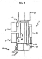
- FIG. 5 shows an example of the hand construction having such a slide mechanism, in which the image capturing means 4 of the visual sensor is not fixedly mounted to the mount 41 at the robot arm end 10, but mounted thereto through a slider mechanism 42 for moving the image capturing means 4 in a direction parallel to the axis of the robot arm end 10.
- Reference numeral 43 denotes a carrier for the image capturing means 4.
- the carrier 43 is arranged to be movable on the slider mechanism 42, thus making the image capturing means 4 movable.
- the slider mechanism 42 is connected to the robot controller 2, so that the position of the carrier 43, and by extension the position (slide position) of the image capturing means 4, is controlled in accordance with a command supplied from the robot controller 2.
- This method for interaction avoidance is effective especially when, as shown in FIG. 6 , the object 13c to be subject to the image capturing or the holding is located deeply below the surrounding objects.
- the position, shown by the solid line, of the image capturing means 4 indicates an example of the slide position for capturing the image of the object 13c
- the position shown by the dotted line of the image capturing means 4 indicates an example of the slide position for holding the object 13c.
- objects 13 in the container 11 are taken out one by one.
- the following is a typical outline of procedures, after which the objects 13 are taken out by the holding means 35 of the hand 3.
- Step S1 a determination is made as to whether or not the object attempted to be taken out is in an upright orientation.
- images of an object is taken from different directions using the image capturing means 4, and based on these images, taught image models are prepared beforehand in the control processor 5.
- the image of the object taken in the second image capturing position is compared with the taught image models, and the taught image model with the highest conformity is selected to determine whether the object is in an upright orientation or not.
- Step S2 If the result of determination at Step S1 is negative (No), whether or not the object attempted to be taken out overlaps another object is determined (Step S2). In this determination, as for objects of annular ring shape, the determination result is affirmative (Yes), if the oval arc profile of the object attempted to be taken out is disconnected by another oval arc profile. If not so, the determination result is negative.
- Step S3 inside-holding is selected (Step S3), in which the object 21 is held from inside by opening the closing members 35a, 35b (see, FIGS. 2a and 2b ) of the holding means 35. Specifically, in the inside-holding, the holding means 35 is moved close to the object 21 from above, and then the closing members 35a, 35b are opened to be brought in urged contact with the inner peripheral surface of the object 21, whereby the object 21 is held.
- Step S4 outside-holding is selected (Step S4), in which an arcuate portion of the object 22, not covered by another object 23, is held from both sides by closing the closing members 35a, 35b. Specifically, when the object 22 overlaps another object 23, the holding means 35 is moved close to the object 22 from above, and then the closing members 35a, 35b are closed to be brought in urged contact with the inner and outer peripheral surfaces of the object 22, respectively, whereby the object 22 is held.
- Step S5 whether or not an empty area is present on both sides of the object attempted to be taken out.
- an empty area is present on both sides (object 24)
- a narrow band-shaped profile representing another upright object
- object 25 it is determined that an empty area is present on one side (object 25).
- other upright objects 27, 29 are detected on both sides, it is determined that no empty area is present (object 28).
- top-holding, side-holding, and unable to hold are selected, respectively (Steps S6, S7 and S8).
- the top-holding and the side-holding belong to a so-called vertical holding.
- the holding means 35 In the top-holding, the holding means 35 is moved close to the object 24 from above, and then the closing members 35a, 35b are closed to be brought in urged contact with both end surfaces of the object 24, respectively, whereby the object 24 is held.
- the holding means 35 In the side-holding for a case where an empty space is present only on one side of the object 25, the holding means 35 is moved close to the object 25 from lateral side, utilizing the empty space, and then the closing members 35a, 35b are closed to be brought in urged contact with the inner and outer peripheral surfaces of the object 25, respectively, thus holding the object 25.
- Step S8 If the unable to hold condition is determined at Step S8, the object to be taken out at this time is changed to the second best object that can be determined according to the rules in procedure (4). Whereupon, the procedure (5) and subsequent procedures are repeated.
- Step S3 S4, S6, or S7 is reached. If Step S8 is reached for all the objects detected in procedure (3), an alarm is output and the system is caused to stop, though this situation hardly occurs.
- Step S8 is reached for all the objects detected in procedure (3), an alarm is output and the system is caused to stop, though this situation hardly occurs.
- other objects are taken out ahead of the same. In general, therefore, there is a high possibility that a space is produced at least one side of the object that was determined as being unable to hold.
- telescopic means for changing the orientation of the holding means of the hand it may be a telescopic mechanism having an electric motor serving as a drive source, instead of a hydraulic cylinder used in the embodiment.
- a mechanism having a rotary mechanism provided at one end of a coupling member and driven by an electric motor, for directly rotating the holding means to change the orientation of the same.
Claims (7)
- Gegenstandsentnahmevorrichtung zur Entnahme eines Gegenstandes (13), umfassend:einen Roboter (1) mit einem Roboterarm;eine Hand (3), die an einem distalen Ende (10) des Roboterarms befestigt ist, und die Halteeinrichtungen (35) zum Halten eines Gegenstandes aufweist;einen Optiksensor zum Erfassen eines Zustands der Unterbringung eines zu entnehmenden Gegenstandes; undeine Steuervorrichtung (2) zur Erteilung von Befehlen an die Hand (3), worin:dadurch gekennzeichnet, dassdie Hand (3) Ausrichtungswechseleinrichtungen (31-34) aufweist, die sich zum Ändern der Ausrichtung der Halteeinrichtung (35) einsetzen lassen, so dass selektiv eine von mehreren Ausrichtungen angenommen wird, einschließlich einer ersten Ausrichtung und einer zweiten Ausrichtung, die sich in Bezug auf den Roboterarm gemäß einem Befehl von der Steuervorrichtung (2) voneinander unterscheiden, die zum Erteilen des Befehls an die Hand (3) vor dem Halten des Gegenstandes gemäß dem Zustand der Unterbringung des zu entnehmenden Gegenstandes ausgelegt ist, wie es durch den Optiksensor erfasst wird, wodurch die Ausrichtung der Halteeinrichtung (35) vor dem Halten des Gegenstandes selektiv geändert wird;
der Optiksensor Bildaufnahmeeinrichtungen (4) aufweist, die am distalen Ende (10) des Roboterarms über einen Gleitmechanismus (42, 43) befestigt sind, der sich in Richtungen weg vom distalen Ende (10) des Roboterarms und zu diesem hin bewegen lässt, wobei die Bildaufnahmeeinrichtung (4) beim Aufnehmen eines Bildes in Richtung weg vom distalen Ende (10) des Roboterarms bewegt wird, und sie in Richtung zum distalen Ende (10) des Roboterarms bewegt wird, wenn die Halteeinrichtung (35) den Gegenstand hält. - Gegenstandsentnahmevorrichtung nach Anspruch 1, wobei die erste Ausrichtung derart eingestellt ist, dass in den mehreren Ausrichtungen eine Richtung einer Halteachse (A) der Halteeinrichtung (35) nächst einer Richtung einer Drehachse (B) des distalen Endes (10) des Roboterarms ist, so dass ein festgelegter Winkel (θ1) ungleich Null Grad zwischen der Richtung der Halteachse (A) und der Richtung der Drehachse (B) des distalen Endes (10) des Roboterarms gebildet wird.
- Gegenstandsentnahmevorrichtung nach Anspruch 2, worin ein Halte-Zentrum (C) der Halteeinrichtung (35) von der Mittelachse (D) eines proximalen Abschnitts davon versetzt ist.
- Gegenstandsentnahmevorrichtung nach Anspruch 1, 2 oder 3, wobei ein Winkel gleich oder kleiner 45° zwischen einer Halteachse (A) der Haltevorrichtung (35) und einer Drehachse (B) des distalen Endes (10) des Roboterarms gebildet wird, wenn die Halteeinrichtung (35) die erste Ausrichtung annimmt.
- Gegenstandsentnahmevorrichtung nach Anspruch 4, wobei ein Winkel im Wesentlichen gleich 90° zwischen der Halteachse (A) und der Drehachse (B) des distalen Endes (10) des Roboterarms gebildet wird, wenn die Halteeinrichtung (35) die zweite Ausrichtung annimmt.
- Gegenstandsentnahmevorrichtung nach einem vorhergehenden Anspruch, wobei der Optiksensor aufweist Einrichtungen zum Speichern eingelernter Bildmodelle eines Gegenstandes, wie er aus verschiedenen Richtungen gesehen wird, und Einrichtungen zum Vergleichen eines aufgenommenen Bildes des Gegenstandes mit den eingelernten Bildmodellen und zum Auswählen von einem der eingelernten Bildmodelle gemäß dem Konformitätsgrad, und
worin die Ausrichtungswechseleinrichtungen (31-34) zum Ändern der Ausrichtung der Halteeinrichtung (35) gemäß dem eingelernten Bildmodell vor dem Halten des Gegenstandes ausgelegt sind. - Gegenstandsentnahmevorrichtung nach einem vorhergehenden Anspruch, wobei der Optiksensor zum Erfassen eines Zustands der Überlappung von Gegenständen ausgelegt ist, wodurch eine Halteposition eines Gegenstandes durch die Halteeinrichtung (35) gemäß dem erfassten Zustand geändert wird.
Applications Claiming Priority (2)
| Application Number | Priority Date | Filing Date | Title |
|---|---|---|---|
| JP2003022373 | 2003-01-30 | ||
| JP2003022373A JP3805310B2 (ja) | 2003-01-30 | 2003-01-30 | ワーク取出し装置 |
Publications (3)
| Publication Number | Publication Date |
|---|---|
| EP1442848A2 EP1442848A2 (de) | 2004-08-04 |
| EP1442848A3 EP1442848A3 (de) | 2006-09-13 |
| EP1442848B1 true EP1442848B1 (de) | 2008-11-19 |
Family
ID=32652897
Family Applications (1)
| Application Number | Title | Priority Date | Filing Date |
|---|---|---|---|
| EP04250500A Expired - Fee Related EP1442848B1 (de) | 2003-01-30 | 2004-01-29 | Roboterhand zur Entnahme von Gegenständen mit Vorrichtung zum Ändern die Ausrichtung der Hand |
Country Status (4)
| Country | Link |
|---|---|
| US (1) | US7474939B2 (de) |
| EP (1) | EP1442848B1 (de) |
| JP (1) | JP3805310B2 (de) |
| DE (1) | DE602004017795D1 (de) |
Cited By (3)
| Publication number | Priority date | Publication date | Assignee | Title |
|---|---|---|---|---|
| DE102014005758B4 (de) * | 2013-04-18 | 2015-06-18 | Fanuc Corporation | Robotersystem, aufweisend einen Roboter zur Beförderung eines Werkstücks |
| CN108724173A (zh) * | 2017-12-04 | 2018-11-02 | 北京猎户星空科技有限公司 | 一种对机器人运动的控制方法、装置、设备及机器人 |
| DE102022130461B3 (de) | 2022-11-17 | 2024-01-25 | Aumann AG | Verfahren und Vorrichtung zum roboterbasierten Vereinzeln von Objekten aus einem Aufnahmebehälter |
Families Citing this family (120)
| Publication number | Priority date | Publication date | Assignee | Title |
|---|---|---|---|---|
| JP3805310B2 (ja) * | 2003-01-30 | 2006-08-02 | ファナック株式会社 | ワーク取出し装置 |
| JP3930490B2 (ja) * | 2004-04-23 | 2007-06-13 | ファナック株式会社 | 物品取出し装置 |
| SE529377C2 (sv) * | 2005-10-18 | 2007-07-24 | Morphic Technologies Ab Publ | Metod och arrangemang för att lokalisera och plocka upp föremål från en bärare |
| US20070267043A1 (en) * | 2005-11-10 | 2007-11-22 | Hugo Salamanca | Robot system and method for washing and unclogging procedures of machines under maintenance |
| US20070185610A1 (en) * | 2005-11-10 | 2007-08-09 | Hugo Salamanca | Robot system and method for the application of dislodging material and pin positioning in casting wheels |
| US20070144894A1 (en) * | 2005-11-10 | 2007-06-28 | Hugo Salamanca | Robot system and method for cathode stripping in electrometallurgical and industrial processes |
| US20070152616A1 (en) * | 2005-11-10 | 2007-07-05 | Hugo Salamanca | Robot system and method for cathode selection and handling procedures after the harvest |
| US20070299556A1 (en) * | 2005-11-10 | 2007-12-27 | Hugo Salamanca | Robot system and method for scrap bundling in metal smelting and refining processes |
| US20090101179A1 (en) * | 2005-11-10 | 2009-04-23 | Hugo Salamanca | Robot system and method for molybdenum roasting furnaces cleaning procedures |
| US20090121061A1 (en) * | 2005-11-10 | 2009-05-14 | Hugo Salamanca | Robot system and method for unblocking the primary crusher |
| US20100057254A1 (en) * | 2006-11-13 | 2010-03-04 | Salamanca Hugo P | Methods for using robotics in mining and post-mining processing |
| US7746018B2 (en) * | 2005-11-10 | 2010-06-29 | MI Robotic Solutions | Robot system and method for reposition and/or removal of base plates from cathode stripping machines in electrometallurgical processes |
| US20070180678A1 (en) * | 2005-11-10 | 2007-08-09 | Hugo Salamanca | Robot system and method for bolt removal from SAG and/or ball mills in ore concentration processes |
| US20090099688A1 (en) * | 2005-11-10 | 2009-04-16 | Hugo Salamanca | Integral robot system and method for the dislodging process and/or anode handling from casting wheels |
| US8418830B2 (en) * | 2005-11-10 | 2013-04-16 | Mi Robotic Solutions (Mirs) | Robot system and method for removing sticks and/or foreign elements from conveyor belts |
| US20090177324A1 (en) * | 2005-11-10 | 2009-07-09 | Hugo Salamanca | Robot system and method for maxibags sampling in ore concentration processes |
| FR2896441B1 (fr) * | 2006-01-23 | 2009-07-03 | Jerome Grosbois | Procede et systeme permettant la prehension automatisee de piece(s) |
| JP4087874B2 (ja) | 2006-02-01 | 2008-05-21 | ファナック株式会社 | ワーク取り出し装置 |
| JP2007334678A (ja) * | 2006-06-15 | 2007-12-27 | Fanuc Ltd | ロボットシミュレーション装置 |
| US7313464B1 (en) * | 2006-09-05 | 2007-12-25 | Adept Technology Inc. | Bin-picking system for randomly positioned objects |
| DE102007026956A1 (de) * | 2007-06-12 | 2008-12-18 | Kuka Innotec Gmbh | Verfahren und System zum Roboter geführten Depalettieren von Reifen |
| JP2009000782A (ja) * | 2007-06-21 | 2009-01-08 | Idec Corp | ロボット制御システムおよびロボットハンド |
| JP5448326B2 (ja) * | 2007-10-29 | 2014-03-19 | キヤノン株式会社 | 把持装置および把持装置制御方法 |
| DE102007060653A1 (de) * | 2007-12-15 | 2009-06-18 | Abb Ag | Positionsermittlung eines Objektes |
| JP5082895B2 (ja) * | 2008-01-31 | 2012-11-28 | セイコーエプソン株式会社 | ロボットビジョンシステム |
| US9789986B2 (en) * | 2009-02-26 | 2017-10-17 | Vanrx Pharmasystems Inc. | Robotic filling systems and methods |
| US20090223592A1 (en) | 2008-03-04 | 2009-09-10 | Vanrx Pharmaceuticals, Inc. | Robotic filling systems and methods |
| JP5265296B2 (ja) * | 2008-10-10 | 2013-08-14 | 本田技研工業株式会社 | ワーク取り出し方法 |
| DE102009001894B4 (de) * | 2009-03-26 | 2018-06-28 | pmdtechnologies ag | Robotersystem mit 3D-Kamera |
| IT1394181B1 (it) * | 2009-05-07 | 2012-06-01 | Marchesini Group Spa | Metodo di segmentazione basato sulle caratteristiche per segmentare una pluralita' di articoli duplicati disposti alla rinfusa e gruppo che attua tale metodo per alimentare una macchina confezionatrice |
| JP5500926B2 (ja) * | 2009-09-29 | 2014-05-21 | キヤノン株式会社 | 物体把持制御方法及び装置 |
| JP5528095B2 (ja) * | 2009-12-22 | 2014-06-25 | キヤノン株式会社 | ロボットシステム、その制御装置及び方法 |
| JP5229253B2 (ja) * | 2010-03-11 | 2013-07-03 | 株式会社安川電機 | ロボットシステム及びロボット装置並びにワーク取り出し方法 |
| JP2012016806A (ja) * | 2010-07-09 | 2012-01-26 | Kobe Steel Ltd | 溶接用ロボット |
| JP5618067B2 (ja) * | 2010-08-23 | 2014-11-05 | 株式会社Ihi | バラ積みピッキング装置および方法 |
| JP5685027B2 (ja) * | 2010-09-07 | 2015-03-18 | キヤノン株式会社 | 情報処理装置、物体把持システム、ロボットシステム、情報処理方法、物体把持方法およびプログラム |
| JP2012056017A (ja) * | 2010-09-09 | 2012-03-22 | Honda Motor Co Ltd | ワーク搬送装置およびワーク搬送方法 |
| JP5895337B2 (ja) | 2010-09-15 | 2016-03-30 | セイコーエプソン株式会社 | ロボット |
| JP5682810B2 (ja) | 2010-09-15 | 2015-03-11 | セイコーエプソン株式会社 | ロボット |
| KR101743926B1 (ko) * | 2010-09-20 | 2017-06-08 | 삼성전자주식회사 | 로봇 및 그 제어방법 |
| JP5767464B2 (ja) * | 2010-12-15 | 2015-08-19 | キヤノン株式会社 | 情報処理装置、情報処理装置の制御方法、およびプログラム |
| JP2012152860A (ja) * | 2011-01-26 | 2012-08-16 | Toyota Motor Corp | 把持装置およびその制御方法 |
| JP4975870B1 (ja) | 2011-02-09 | 2012-07-11 | ファナック株式会社 | マスキング治具を用いたマスキング装置 |
| JP5533727B2 (ja) * | 2011-02-18 | 2014-06-25 | 株式会社安川電機 | ワークピッキングシステム |
| JP5085749B2 (ja) * | 2011-02-21 | 2012-11-28 | ファナック株式会社 | 棒状部材の搬送装置 |
| WO2013002099A1 (ja) * | 2011-06-29 | 2013-01-03 | 三菱電機株式会社 | 部品供給装置 |
| JP6021484B2 (ja) | 2011-08-04 | 2016-11-09 | オリンパス株式会社 | 医療用マニピュレータ |
| WO2013018861A1 (ja) | 2011-08-04 | 2013-02-07 | オリンパス株式会社 | 医療用マニピュレータおよびその制御方法 |
| CN103648425B (zh) | 2011-08-04 | 2016-10-19 | 奥林巴斯株式会社 | 医疗用机械手和手术支援装置 |
| JP6000641B2 (ja) | 2011-08-04 | 2016-10-05 | オリンパス株式会社 | マニピュレータシステム |
| JP6021353B2 (ja) | 2011-08-04 | 2016-11-09 | オリンパス株式会社 | 手術支援装置 |
| JP5953058B2 (ja) | 2011-08-04 | 2016-07-13 | オリンパス株式会社 | 手術支援装置およびその着脱方法 |
| JP5936914B2 (ja) | 2011-08-04 | 2016-06-22 | オリンパス株式会社 | 操作入力装置およびこれを備えるマニピュレータシステム |
| JP6081061B2 (ja) * | 2011-08-04 | 2017-02-15 | オリンパス株式会社 | 手術支援装置 |
| US9161772B2 (en) | 2011-08-04 | 2015-10-20 | Olympus Corporation | Surgical instrument and medical manipulator |
| JP5841451B2 (ja) | 2011-08-04 | 2016-01-13 | オリンパス株式会社 | 手術器具およびその制御方法 |
| JP5931497B2 (ja) | 2011-08-04 | 2016-06-08 | オリンパス株式会社 | 手術支援装置およびその組立方法 |
| JP6005950B2 (ja) | 2011-08-04 | 2016-10-12 | オリンパス株式会社 | 手術支援装置及びその制御方法 |
| JP6009840B2 (ja) | 2011-08-04 | 2016-10-19 | オリンパス株式会社 | 医療機器 |
| JP5852364B2 (ja) * | 2011-08-26 | 2016-02-03 | キヤノン株式会社 | 情報処理装置、情報処理装置の制御方法、およびプログラム |
| JP5447483B2 (ja) * | 2011-10-04 | 2014-03-19 | 株式会社安川電機 | ロボットシステムおよび被加工物の製造方法 |
| US8930009B2 (en) * | 2011-10-20 | 2015-01-06 | Kabushiki Kaisha Yaskawa Denki | Robot system and processed object manufacturing method |
| FR2983761A1 (fr) * | 2011-12-07 | 2013-06-14 | Centre Nat Recherche | Dispositif microtechnique a capteur d'image |
| JP5266377B2 (ja) | 2011-12-19 | 2013-08-21 | ファナック株式会社 | 物品の姿勢を修正する機能を備えた取出し装置 |
| JP5516610B2 (ja) * | 2012-01-19 | 2014-06-11 | 株式会社安川電機 | ロボット、ロボットハンドおよびロボットハンドの保持位置調整方法 |
| KR101800189B1 (ko) * | 2012-04-30 | 2017-11-23 | 삼성전자주식회사 | 수술 로봇의 힘 제어 장치 및 방법 |
| JP5642738B2 (ja) * | 2012-07-26 | 2014-12-17 | ファナック株式会社 | バラ積みされた物品をロボットで取出す装置及び方法 |
| JP5480340B2 (ja) | 2012-07-26 | 2014-04-23 | ファナック株式会社 | ローラ装置を用いた取出しロボットシステム |
| JP5469216B2 (ja) * | 2012-07-31 | 2014-04-16 | ファナック株式会社 | バラ積みされた物品をロボットで取出す装置 |
| JP6195333B2 (ja) * | 2012-08-08 | 2017-09-13 | キヤノン株式会社 | ロボット装置 |
| DE102013013114A1 (de) * | 2012-08-17 | 2014-02-20 | Liebherr-Verzahntechnik Gmbh | Vorrichtung zum automatisierten Entnehmen von in einem Behälter angeordneten Werkstücken |
| JP5620445B2 (ja) * | 2012-09-13 | 2014-11-05 | ファナック株式会社 | 選択条件に基づいてロボットの保持位置姿勢を決定する物品取出装置 |
| KR102056664B1 (ko) * | 2012-10-04 | 2019-12-17 | 한국전자통신연구원 | 센서를 이용한 작업 방법 및 이를 수행하는 작업 시스템 |
| US9272421B2 (en) * | 2013-01-07 | 2016-03-01 | Milos Misha Subotincic | Visually controlled end effector |
| JP5768827B2 (ja) | 2013-03-14 | 2015-08-26 | 株式会社安川電機 | ロボットシステムおよびワークの搬送方法 |
| JP5983506B2 (ja) * | 2013-04-04 | 2016-08-31 | トヨタ自動車株式会社 | 把持対象物の把持パターン検出方法およびロボット |
| JP5929854B2 (ja) * | 2013-07-31 | 2016-06-08 | 株式会社安川電機 | ロボットシステムおよび被加工物の製造方法 |
| WO2015029142A1 (ja) * | 2013-08-27 | 2015-03-05 | 株式会社安川電機 | 組立システムおよび組立品の生産方法 |
| JP5705932B2 (ja) * | 2013-08-30 | 2015-04-22 | ファナック株式会社 | 磁石搬送位置決め装置 |
| JP6429450B2 (ja) * | 2013-10-31 | 2018-11-28 | キヤノン株式会社 | 情報処理装置、情報処理方法 |
| US9598203B2 (en) * | 2013-12-24 | 2017-03-21 | Ookuma Electronic Co., Ltd. | Injection container storage box device and injection container picking system including the device |
| JP5877857B2 (ja) * | 2014-03-10 | 2016-03-08 | ファナック株式会社 | ワークの取出工程をシミュレーションするロボットシミュレーション装置 |
| JP5778311B1 (ja) * | 2014-05-08 | 2015-09-16 | 東芝機械株式会社 | ピッキング装置およびピッキング方法 |
| WO2017035016A1 (en) | 2015-08-26 | 2017-03-02 | Berkshire Grey Inc. | Systems and methods for providing contact detection in an articulated arm |
| CN108495738B (zh) | 2015-09-01 | 2022-01-04 | 伯克希尔格雷股份有限公司 | 用于提供动态机器人控制系统的系统和方法 |
| US11370128B2 (en) | 2015-09-01 | 2022-06-28 | Berkshire Grey Operating Company, Inc. | Systems and methods for providing dynamic robotic control systems |
| ES2913085T3 (es) | 2015-09-09 | 2022-05-31 | Berkshire Grey Operating Company Inc | Sistemas y métodos para proporcionar una iluminación comunicativa dinámica en un entorno robótico |
| ES2952517T3 (es) | 2015-09-11 | 2023-10-31 | Berkshire Grey Operating Company Inc | Sistemas robóticos y métodos para identificar y procesar diversos objetos |
| JP6711591B2 (ja) | 2015-11-06 | 2020-06-17 | キヤノン株式会社 | ロボット制御装置およびロボット制御方法 |
| WO2017083574A1 (en) * | 2015-11-13 | 2017-05-18 | Berkshire Grey Inc. | Sortation systems and methods for providing sortation of a variety of obejcts |
| US9937532B2 (en) | 2015-12-18 | 2018-04-10 | Berkshire Grey Inc. | Perception systems and methods for identifying and processing a variety of objects |
| ITUB20159767A1 (it) * | 2015-12-30 | 2017-06-30 | Tiesse Robot S P A | Manipolatore, in particolare per il prelievo di oggetti collocati in un cestone |
| CA3169689C (en) | 2016-01-08 | 2024-04-02 | Berkshire Grey Operating Company, Inc. | Systems and methods for acquiring and moving objects |
| EP3405312B1 (de) * | 2016-01-20 | 2021-08-11 | Soft Robotics, Inc. | Robotische weiche greifer für überladene greifumgebungen, bewegungen mit hoher beschleunigung, manipulation von nahrungsmitteln sowie automatisierte systeme zur regalbedienung |
| CA3178174A1 (en) | 2016-02-08 | 2017-08-17 | Berkshire Grey Operating Company, Inc. | Systems and methods for providing processing of a variety of objects employing motion planning |
| CN106272421B (zh) * | 2016-04-09 | 2018-07-13 | 广州佳帆计算机有限公司 | 一种程控工业机器人 |
| CN105666494B (zh) * | 2016-04-09 | 2017-07-14 | 福州环亚众志计算机有限公司 | 机器人控制方法以及机器人系统 |
| CN105856232A (zh) * | 2016-05-30 | 2016-08-17 | 先驱智能机械(深圳)有限公司 | 物体的抓取方法及抓取系统 |
| CN108715361A (zh) * | 2016-06-13 | 2018-10-30 | 金祝英 | 一种用于港口作业的卸货装置 |
| JP6842753B2 (ja) * | 2016-11-09 | 2021-03-17 | 株式会社技研システック | ワークの把持位置指示システムおよびピッキング装置 |
| CN106426215B (zh) * | 2016-11-25 | 2019-04-12 | 许国梁 | 一种商场发毛绒玩具用机器人 |
| CA3139272C (en) | 2016-12-09 | 2023-07-25 | Berkshire Grey, Inc. | Systems and methods for processing objects provided in vehicles |
| EP3593960A4 (de) * | 2017-03-06 | 2020-01-22 | Fuji Corporation | Datenstruktur zur erzeugung von bildverarbeitungsdaten und verfahren zur erzeugung von bildverarbeitungsdaten |
| CN115319788A (zh) | 2017-03-06 | 2022-11-11 | 伯克希尔格雷运营股份有限公司 | 用于有效地移动各种物体的系统和方法 |
| JP6438512B2 (ja) * | 2017-03-13 | 2018-12-12 | ファナック株式会社 | 機械学習により補正した計測データでワークの取り出しを行うロボットシステム、計測データ処理装置および計測データ処理方法 |
| US11179856B2 (en) | 2017-03-30 | 2021-11-23 | Soft Robotics, Inc. | User-assisted robotic control systems |
| JP2018176334A (ja) * | 2017-04-10 | 2018-11-15 | キヤノン株式会社 | 情報処理装置、計測装置、システム、干渉判定方法および物品の製造方法 |
| JP6546618B2 (ja) | 2017-05-31 | 2019-07-17 | 株式会社Preferred Networks | 学習装置、学習方法、学習モデル、検出装置及び把持システム |
| CN116945132A (zh) | 2017-08-02 | 2023-10-27 | 伯克希尔格雷营业股份有限公司 | 用于获取和移动具有复杂的外表面的物体的系统和方法 |
| JP6902208B2 (ja) * | 2017-11-14 | 2021-07-14 | オムロン株式会社 | 把持方法、把持システム及びプログラム |
| JP6914528B2 (ja) * | 2017-11-21 | 2021-08-04 | ウエノテックス株式会社 | タイヤ移動装置および廃タイヤ処理システム |
| WO2019106720A1 (ja) * | 2017-11-28 | 2019-06-06 | 株式会社Fuji | 部品移載装置 |
| CN108724176B (zh) * | 2018-03-21 | 2021-03-05 | 北京猎户星空科技有限公司 | 机器人转动的控制方法、装置、机器人及存储介质 |
| CN109514530A (zh) * | 2018-11-29 | 2019-03-26 | 浙江树人学院 | 一种机械臂及其抓取方法 |
| CN109848987B (zh) * | 2019-01-22 | 2022-02-01 | 天津大学 | 一种并联机器人视觉伺服控制方法 |
| WO2021063412A1 (zh) * | 2019-09-30 | 2021-04-08 | 深圳市海柔创新科技有限公司 | 取、放货控制方法、装置、搬运装置及搬运机器人 |
| CN116133804A (zh) | 2020-07-22 | 2023-05-16 | 伯克希尔格雷营业股份有限公司 | 用于使用被动折叠真空夹持器进行物体处理的系统和方法 |
| EP4035850A1 (de) | 2021-02-02 | 2022-08-03 | Pick-It nv | Endeffektor zum aufnehmen von objekten |
| US11866269B2 (en) | 2021-10-06 | 2024-01-09 | Berkshire Grey Operating Company, Inc. | Dynamic processing of objects provided in elevated vehicles with evacuation systems and methods for receiving objects |
| DE102022202587A1 (de) | 2022-03-16 | 2023-09-21 | Volkswagen Aktiengesellschaft | Entnahmevorrichtung zur Entnahme von Werkstücken aus einem Werkstückbehälter |
Family Cites Families (34)
| Publication number | Priority date | Publication date | Assignee | Title |
|---|---|---|---|---|
| US4402053A (en) * | 1980-09-25 | 1983-08-30 | Board Of Regents For Education For The State Of Rhode Island | Estimating workpiece pose using the feature points method |
| US4412293A (en) * | 1981-03-30 | 1983-10-25 | Kelley Robert B | Robot system which acquires cylindrical workpieces from bins |
| US5608847A (en) * | 1981-05-11 | 1997-03-04 | Sensor Adaptive Machines, Inc. | Vision target based assembly |
| US4753569A (en) * | 1982-12-28 | 1988-06-28 | Diffracto, Ltd. | Robot calibration |
| JPS59183389A (ja) | 1983-04-04 | 1984-10-18 | Atsumi Denki Kk | 赤外線侵入者検知装置 |
| US4613269A (en) * | 1984-02-28 | 1986-09-23 | Object Recognition Systems, Inc. | Robotic acquisition of objects by means including histogram techniques |
| JPS60200103A (ja) * | 1984-03-26 | 1985-10-09 | Hitachi Ltd | 光切断線抽出回路 |
| JPS6126106A (ja) * | 1984-07-16 | 1986-02-05 | Fanuc Ltd | 工具位置補正方式 |
| JPS6171302A (ja) * | 1984-09-14 | 1986-04-12 | Toshiba Corp | ロボットハンド用近接センサ装置 |
| JPS61281305A (ja) * | 1985-06-06 | 1986-12-11 | Toyota Motor Corp | 多関節ロボツト制御装置 |
| US4707647A (en) * | 1986-05-19 | 1987-11-17 | Gmf Robotics Corporation | Gray scale vision method and system utilizing same |
| US5219264A (en) * | 1986-09-19 | 1993-06-15 | Texas Instruments Incorporated | Mobile robot on-board vision system |
| FR2605834B1 (fr) * | 1986-11-05 | 1989-01-06 | Pellenc & Motte | Machine robotisee, notamment pour la recolte de fruits |
| US5177563A (en) * | 1989-02-01 | 1993-01-05 | Texas A&M University System | Method and apparatus for locating physical objects |
| US4985846A (en) * | 1989-05-11 | 1991-01-15 | Fallon Patrick J | Acoustical/optical bin picking system |
| US5825980A (en) * | 1989-05-26 | 1998-10-20 | Canon Kabushiki Kaisha | Robot hand structure, and method of selecting hand structure |
| JP3064348B2 (ja) * | 1990-08-02 | 2000-07-12 | 豊田工機株式会社 | ロボット制御装置 |
| US5325468A (en) * | 1990-10-31 | 1994-06-28 | Sanyo Electric Co., Ltd. | Operation planning system for robot |
| DE69221070T2 (de) * | 1991-09-05 | 1998-01-15 | Canon Kk | Videokonferenzsystem und Endgerät zur Verwendung in demselben |
| KR950010972B1 (ko) * | 1991-12-07 | 1995-09-26 | 포항종합제철주식회사 | 업셋(offset)이 있는 로보트손목의 기구변수 결정법 |
| US5321353A (en) * | 1992-05-13 | 1994-06-14 | Storage Technolgy Corporation | System and method for precisely positioning a robotic tool |
| JPH07116984A (ja) * | 1993-08-30 | 1995-05-09 | Sanyo Electric Co Ltd | ロボットハンド及びそれを使用した部品供給装置 |
| US5471541A (en) * | 1993-11-16 | 1995-11-28 | National Research Council Of Canada | System for determining the pose of an object which utilizes range profiles and synethic profiles derived from a model |
| JP3225740B2 (ja) | 1994-05-25 | 2001-11-05 | 株式会社デンソー | 山積み部品の高速ピッキング装置 |
| US5838882A (en) * | 1996-10-31 | 1998-11-17 | Combustion Engineering, Inc. | Dynamic position tracking and control of robots |
| US5751610A (en) * | 1996-10-31 | 1998-05-12 | Combustion Engineering, Inc. | On-line robot work-cell calibration |
| US5944476A (en) * | 1997-03-26 | 1999-08-31 | Kensington Laboratories, Inc. | Unitary specimen prealigner and continuously rotatable multiple link robot arm mechanism |
| JPH11123681A (ja) * | 1997-10-24 | 1999-05-11 | Mitsubishi Electric Corp | ピッキング装置およびピッキング方法 |
| JP3133714B2 (ja) * | 1997-10-30 | 2001-02-13 | 日本たばこ産業株式会社 | たばこの巻のピッキング供給装置 |
| JP2002200588A (ja) | 2000-12-28 | 2002-07-16 | Denso Corp | ロボットによる把持可能部品の把持位置検出方法及びその装置 |
| JP3782679B2 (ja) | 2001-05-09 | 2006-06-07 | ファナック株式会社 | 干渉回避装置 |
| JP3702257B2 (ja) * | 2002-08-23 | 2005-10-05 | ファナック株式会社 | ロボットハンドリング装置 |
| JP3805310B2 (ja) * | 2003-01-30 | 2006-08-02 | ファナック株式会社 | ワーク取出し装置 |
| US7313464B1 (en) * | 2006-09-05 | 2007-12-25 | Adept Technology Inc. | Bin-picking system for randomly positioned objects |
-
2003
- 2003-01-30 JP JP2003022373A patent/JP3805310B2/ja not_active Expired - Lifetime
-
2004
- 2004-01-29 EP EP04250500A patent/EP1442848B1/de not_active Expired - Fee Related
- 2004-01-29 DE DE602004017795T patent/DE602004017795D1/de not_active Expired - Lifetime
- 2004-01-30 US US10/767,193 patent/US7474939B2/en active Active
Cited By (3)
| Publication number | Priority date | Publication date | Assignee | Title |
|---|---|---|---|---|
| DE102014005758B4 (de) * | 2013-04-18 | 2015-06-18 | Fanuc Corporation | Robotersystem, aufweisend einen Roboter zur Beförderung eines Werkstücks |
| CN108724173A (zh) * | 2017-12-04 | 2018-11-02 | 北京猎户星空科技有限公司 | 一种对机器人运动的控制方法、装置、设备及机器人 |
| DE102022130461B3 (de) | 2022-11-17 | 2024-01-25 | Aumann AG | Verfahren und Vorrichtung zum roboterbasierten Vereinzeln von Objekten aus einem Aufnahmebehälter |
Also Published As
| Publication number | Publication date |
|---|---|
| DE602004017795D1 (de) | 2009-01-02 |
| US7474939B2 (en) | 2009-01-06 |
| EP1442848A3 (de) | 2006-09-13 |
| JP3805310B2 (ja) | 2006-08-02 |
| JP2004230513A (ja) | 2004-08-19 |
| EP1442848A2 (de) | 2004-08-04 |
| US20040186624A1 (en) | 2004-09-23 |
Similar Documents
| Publication | Publication Date | Title |
|---|---|---|
| EP1442848B1 (de) | Roboterhand zur Entnahme von Gegenständen mit Vorrichtung zum Ändern die Ausrichtung der Hand | |
| JP4390758B2 (ja) | ワーク取出し装置 | |
| EP1589483B1 (de) | System zum Greifen von Objekten | |
| JP5229253B2 (ja) | ロボットシステム及びロボット装置並びにワーク取り出し方法 | |
| KR102115983B1 (ko) | 컨테이너 내에 배치된 공작물을 자동으로 제거하기 위한 장치 | |
| US10836042B2 (en) | Robot system | |
| US9050722B2 (en) | Pickup device capable of determining holding position and posture of robot based on selection condition | |
| US7965055B2 (en) | Control device of work positioning apparatus | |
| US8315735B2 (en) | Production system having cooperating process area between human and robot | |
| US8660685B2 (en) | Robot system and workpiece picking method | |
| JP5849403B2 (ja) | ロボットコントローラー、ロボット、及び、ロボットシステム | |
| US20090198377A1 (en) | Wafer position teaching method and teaching tool | |
| US20060072988A1 (en) | Transfer robot system | |
| EP0260984B1 (de) | Bord-Sichtsystem für bewegliche Roboter | |
| JP5535884B2 (ja) | ワーク取り出し方法 | |
| US9682821B2 (en) | Article transport facility | |
| KR102470613B1 (ko) | 동작 장치의 캘리브레이션 방법, 동작 장치 시스템 및 제어 장치 | |
| JP7376916B2 (ja) | ワーク給除材システム、可搬型ロボット装置及び可搬型ワークストッカ | |
| JP4501102B2 (ja) | 教示治具およびそれを使って教示されるロボットおよびそのロボットの教示方法 | |
| JP3622048B2 (ja) | 無人搬送車 | |
| KR102486009B1 (ko) | 로봇팔을 이용한 디팔레타이징 자동화 시스템 및 방법 | |
| WO2024004654A1 (ja) | ロボットシステムおよびロボット | |
| JP6915085B2 (ja) | 作業機および把持位置探索方法 | |
| WO2024023934A1 (ja) | ワーク取出し装置、ワーク取出し方法及び制御装置 | |
| WO2023012894A1 (ja) | ロボットシステム、制御装置、診断方法および診断プログラム |
Legal Events
| Date | Code | Title | Description |
|---|---|---|---|
| PUAI | Public reference made under article 153(3) epc to a published international application that has entered the european phase |
Free format text: ORIGINAL CODE: 0009012 |
|
| AK | Designated contracting states |
Kind code of ref document: A2 Designated state(s): AT BE BG CH CY CZ DE DK EE ES FI FR GB GR HU IE IT LI LU MC NL PT RO SE SI SK TR |
|
| AX | Request for extension of the european patent |
Extension state: AL LT LV MK |
|
| PUAL | Search report despatched |
Free format text: ORIGINAL CODE: 0009013 |
|
| AK | Designated contracting states |
Kind code of ref document: A3 Designated state(s): AT BE BG CH CY CZ DE DK EE ES FI FR GB GR HU IE IT LI LU MC NL PT RO SE SI SK TR |
|
| AX | Request for extension of the european patent |
Extension state: AL LT LV MK |
|
| 17P | Request for examination filed |
Effective date: 20070307 |
|
| AKX | Designation fees paid |
Designated state(s): DE |
|
| 17Q | First examination report despatched |
Effective date: 20070914 |
|
| GRAP | Despatch of communication of intention to grant a patent |
Free format text: ORIGINAL CODE: EPIDOSNIGR1 |
|
| GRAS | Grant fee paid |
Free format text: ORIGINAL CODE: EPIDOSNIGR3 |
|
| GRAA | (expected) grant |
Free format text: ORIGINAL CODE: 0009210 |
|
| AK | Designated contracting states |
Kind code of ref document: B1 Designated state(s): DE |
|
| REF | Corresponds to: |
Ref document number: 602004017795 Country of ref document: DE Date of ref document: 20090102 Kind code of ref document: P |
|
| PLBE | No opposition filed within time limit |
Free format text: ORIGINAL CODE: 0009261 |
|
| STAA | Information on the status of an ep patent application or granted ep patent |
Free format text: STATUS: NO OPPOSITION FILED WITHIN TIME LIMIT |
|
| 26N | No opposition filed |
Effective date: 20090820 |
|
| REG | Reference to a national code |
Ref country code: DE Ref legal event code: R082 Ref document number: 602004017795 Country of ref document: DE Representative=s name: HL KEMPNER PATENTANWALT, RECHTSANWALT, SOLICIT, DE |
|
| PGFP | Annual fee paid to national office [announced via postgrant information from national office to epo] |
Ref country code: DE Payment date: 20211207 Year of fee payment: 19 |
|
| REG | Reference to a national code |
Ref country code: DE Ref legal event code: R119 Ref document number: 602004017795 Country of ref document: DE |
|
| PG25 | Lapsed in a contracting state [announced via postgrant information from national office to epo] |
Ref country code: DE Free format text: LAPSE BECAUSE OF NON-PAYMENT OF DUE FEES Effective date: 20230801 |