EP1431140A2 - Bordumgebungs-Steuersystem, Bordumgebungs-Steuervorrichtung, und Bordumgebungs-Steuermethode - Google Patents
Bordumgebungs-Steuersystem, Bordumgebungs-Steuervorrichtung, und Bordumgebungs-Steuermethode Download PDFInfo
- Publication number
- EP1431140A2 EP1431140A2 EP20030257968 EP03257968A EP1431140A2 EP 1431140 A2 EP1431140 A2 EP 1431140A2 EP 20030257968 EP20030257968 EP 20030257968 EP 03257968 A EP03257968 A EP 03257968A EP 1431140 A2 EP1431140 A2 EP 1431140A2
- Authority
- EP
- European Patent Office
- Prior art keywords
- vehicle
- boarding environment
- personal authentication
- setting status
- user
- Prior art date
- Legal status (The legal status is an assumption and is not a legal conclusion. Google has not performed a legal analysis and makes no representation as to the accuracy of the status listed.)
- Granted
Links
Images


Classifications
-
- B—PERFORMING OPERATIONS; TRANSPORTING
- B60—VEHICLES IN GENERAL
- B60R—VEHICLES, VEHICLE FITTINGS, OR VEHICLE PARTS, NOT OTHERWISE PROVIDED FOR
- B60R25/00—Fittings or systems for preventing or indicating unauthorised use or theft of vehicles
- B60R25/20—Means to switch the anti-theft system on or off
- B60R25/25—Means to switch the anti-theft system on or off using biometry
- B60R25/257—Voice recognition
-
- B—PERFORMING OPERATIONS; TRANSPORTING
- B60—VEHICLES IN GENERAL
- B60R—VEHICLES, VEHICLE FITTINGS, OR VEHICLE PARTS, NOT OTHERWISE PROVIDED FOR
- B60R25/00—Fittings or systems for preventing or indicating unauthorised use or theft of vehicles
- B60R25/20—Means to switch the anti-theft system on or off
- B60R25/2081—Means to switch the anti-theft system on or off combined with personal settings of other vehicle devices, e.g. mirrors, seats, steering wheels
-
- B—PERFORMING OPERATIONS; TRANSPORTING
- B60—VEHICLES IN GENERAL
- B60R—VEHICLES, VEHICLE FITTINGS, OR VEHICLE PARTS, NOT OTHERWISE PROVIDED FOR
- B60R25/00—Fittings or systems for preventing or indicating unauthorised use or theft of vehicles
- B60R25/20—Means to switch the anti-theft system on or off
- B60R25/24—Means to switch the anti-theft system on or off using electronic identifiers containing a code not memorised by the user
- B60R25/241—Means to switch the anti-theft system on or off using electronic identifiers containing a code not memorised by the user whereby access privileges are related to the identifiers
-
- B—PERFORMING OPERATIONS; TRANSPORTING
- B60—VEHICLES IN GENERAL
- B60R—VEHICLES, VEHICLE FITTINGS, OR VEHICLE PARTS, NOT OTHERWISE PROVIDED FOR
- B60R25/00—Fittings or systems for preventing or indicating unauthorised use or theft of vehicles
- B60R25/20—Means to switch the anti-theft system on or off
- B60R25/25—Means to switch the anti-theft system on or off using biometry
- B60R25/252—Fingerprint recognition
-
- B—PERFORMING OPERATIONS; TRANSPORTING
- B60—VEHICLES IN GENERAL
- B60R—VEHICLES, VEHICLE FITTINGS, OR VEHICLE PARTS, NOT OTHERWISE PROVIDED FOR
- B60R2325/00—Indexing scheme relating to vehicle anti-theft devices
- B60R2325/10—Communication protocols, communication systems of vehicle anti-theft devices
- B60R2325/101—Bluetooth
Definitions
- the present invention relates to a boarding environment controlling system, a boarding environment controlling apparatus, and a boarding environment controlling method for controlling the boarding environment of a vehicle.
- the keyless entry system is typically made up of a remote controller carried by the user, and keyless entry equipment installed on board the vehicle.
- the user When getting off and leaving the vehicle, the user illustratively operates the remote controller to lock the doors of the vehicle.
- the remote controller transmits a door locking command wirelessly (e.g., by radio waves) to the vehicle.
- the command when received by the vehicle, causes its doors to be locked automatically.
- the remote controller Before getting into the vehicle, the user operates the remote controller to unlock the doors. In response to the user's operation, the remote controller transmits an unlock command to the vehicle. When received by the vehicle, the command causes its doors to be unlocked automatically.
- the keyless entry system when mounted on board the vehicle, eliminates the need for the user physically to insert the key into the keyhole to lock or unlock the doors. This provides extra convenience to the user.
- the personal authentication system typically matches the fingerprint of the person in possession of the remote controller against previously recorded fingerprints for personal authentication. If a matched fingerprint record provides authentication of the remote controller's owner, that person may operate the remote controller to lock or unlock the vehicle doors. In case of a mismatch, operating the remote controller fails to lock or unlock the doors.
- the personal authentication system thus allows only the user whose has his or her fingerprint registered beforehand to lock or unlock the vehicle doors using the remote controller.
- anyone with his or her fingerprint yet to be registered is unable to lock or unlock the doors. This is an appreciable improvement in security brought about by the keyless entry system.
- a boarding environment controlling system constituted by a communication device and by a boarding environment controlling apparatus which is mounted on a vehicle and which communicates with the communication device.
- the boarding environment controlling system includes: a detecting element which is included in the communication device and which detects a detection target object for personal authentication; a personal authentication processing element for performing a personal authentication process based on the detection target object detected by the detecting element; a registration storing element which, in association with each of persons to be authenticated in the personal authenticating process, stores registration of setting status information denoting a predetermined boarding environment of the vehicle; a door lock controlling element which is included in the boarding environment controlling apparatus and which unlocks doors of the vehicle when any one of the persons is authenticated in the personal authentication process; and a setting status controlling element which is included in the boarding environment controlling apparatus and which, if any one of the persons is authenticated in the personal authentication process, changes the boarding environment setting status of the vehicle in accordance with the setting status information associated with the authenticated person from among the setting status information stored in the registration storing element.
- a boarding environment controlling apparatus includes: a communicating element for communicating with a communication device which detects a detection target object for personal authentication; a registration storing element for storing registration of setting status information denoting a predetermined boarding environment of a vehicle in association with each of persons to be authenticated in a personal authentication process performed in accordance with the detection target object detected by the communication device; a door lock controlling element for unlocking doors of the vehicle when any one of the persons is authenticated in the personal authentication process; and a setting status controlling element which, if any one of the persons is authenticated in the personal authentication process, changes the boarding environment setting status of the vehicle in accordance with the setting status information associated with the authenticated person from among the setting status information stored in the registration storing element.
- a boarding environment controlling method for use with a boarding environment controlling system constituted by a communication device and by a boarding environment controlling apparatus which is mounted on a vehicle and which communicates with the communication device.
- the boarding environment controlling method includes the steps of: detecting a detection target object for personal authentication through the communication device; performing a personal authentication process based on the detection target object detected in the detecting step; storing, into a predetermined storage area, registration of setting status information denoting a predetermined boarding environment of the vehicle in association with each of persons to be authenticated in the personal authenticating process; unlocking doors of the vehicle through the boarding environment controlling apparatus when any one of the persons is authenticated in the personal authentication process; and if any one of the persons is authenticated in the personal authentication process, then changing, through the boarding environment controlling apparatus, the boarding environment setting status of the vehicle in accordance with the setting status information associated with the authenticated person from among the setting status information stored in the storage areas.
- the personal authentication process is performed on the basis of the detection target object detected by the communication device.
- the vehicle doors are first locked or unlocked for the authenticated person. That is, the basic scheme of the invention involves combining a personal authentication system with a keyless entry system on board the vehicle.
- Personal authentication is carried out based on user-specific physical features such as fingerprint or voiceprint.
- user-specific physical features such as fingerprint or voiceprint.
- a particular feature of the invention is that when a person is authenticated in the personal authentication process, boarding environment settings are changed for the sake of the authenticated person in accordance with the boarding environment setting information registered beforehand in association with each of the registered persons. That is, according to the invention, the personal authentication system combined with the keyless entry system is supplemented with the function of automatically setting up a boarding environment optimally fit for each user of the vehicle.
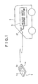
- Fig. 1 shows an overall configuration of a keyless entry system embodying this invention.
- the inventive keyless entry system includes a remote controller 1 and a keyless entry system 3 mounted on board a vehicle 2.
- the remote controller 1, carried by a user has a size small enough to be held by one hand.
- the keyless entry system of this embodiment is combined with a personal authentication system.
- personal authentication involves detecting individually unique physical features such as voiceprint or fingerprint and checking what is detected against previously registered records for a match. This is a technique that ensures a considerably high degree of security.
- the inventive personal authentication system adopts, not exclusively but merely illustratively, a fingerprint matching scheme.
- the enclosure of the remote controller 1 has a fingertip pressing block 1a.
- a predetermined detection method is activated to detect fingerprints from the pressed fingertip.
- the fingerprint detection process need not be executed exclusively by any specific method. Any known or yet-to-be-developed detection methods may be adopted when deemed appropriate.
- One such method may be an imaging method whereby fingerprints are imaged by imaging means such as a CCD camera.
- Another method may be a microswitch-based scheme involving a group of microswitches being individually activated or left inactive to detect a fingerprint pattern.
- the remote controller 1 has illustratively a locking button 1b and an unlocking button 1c as operating elements to be manipulated by the user.
- the locking button 1b and unlocking button 1c are used to lock and unlock the doors of the vehicle 2, respectively. These buttons become operable only after the user has been authenticated by fingerprint matching as mentioned. The personal authentication process involved will be discussed later.
- the user when authenticated, may push the locking button 1b causing the remote controller 1 to transmit a door locking command.
- the command is received by an antenna 37 of the vehicle 2 and acquired by the keyless entry support system 3.
- the keyless entry support system 3 locks the doors of the vehicle 2.
- the user when authenticated, may push the unlocking button 1c causing the remote controller 1 to transmit a door unlocking command.
- the keyless entry support system 3 having received and acquired the command unlocks the doors of the vehicle 2 accordingly.
- a plurality of users may have their fingerprints registered with the keyless entry system. Each of these registered users may be authenticated in the personal authentication process.
- unlocking the vehicle doors by operation of the unlocking button 1c on the remote controller 1 automatically changes various settings such as those of the mirror positions, driver seat positions, and AV equipment (onboard equipment) presets. These settings are changed upon unlocking of the doors so as to establish an optimum boarding environment for the user currently authenticated in the personal authentication process.
- the keyless entry support system 3 on board the vehicle 2 is capable of executing the personal authentication process based on fingerprint matching.
- the remote controller 1 transmits information about the detected fingerprint.
- the system 3 checks the detected fingerprint against previously registered fingerprints for a match.
- the user operates the remote controller 1 to transmit a door locking or unlocking command. Given the command, the system 3 locks or unlocks the vehicle doors accordingly.
- the two functions above i.e., one for executing the personal authentication process based on fingerprint matching, the other for locking or unlocking the vehicle doors based on the transmitted command, work together to implement a viable keyless entry system combined with a personal authentication system.
- the keyless entry support system 3 changes the diverse boarding environment settings optimally to suit a particular user authenticated in the personal authentication process upon locking or unlocking the vehicle doors.
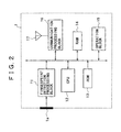
- Fig. 2 is a block diagram depicting a typical internal structure of the remote controller 1.
- the user's fingerprint pressed on and detected by the fingertip pressing block 1a of the controller enclosure is converted by a fingerprint detection processing block 11 into detected information (i.e., fingerprint data) in a predetermined digital data format.
- detected information i.e., fingerprint data
- the fingertip pressing block 1a provides numerous pieces of microswitch on/off information reflecting the fingerprint pattern.
- the fingerprint detection processing block 11 uses the microswitch on/off information, the fingerprint detection processing block 11 generates fingerprint data as the detected information.
- An operation block 15 illustratively represents the locking button 1b and unlocking button 1c shown in Fig. 1.
- the operation block 15 illustratively transmits to a CPU 12 an operation information signal reflecting the button operation. Based on the transmitted operation information signal, the CPU 12 generates a door locking or unlocking command accordingly. The generated command is sent from a communication processing block 16 to the keyless entry support system 3.
- the CPU 12 performs a number of processes in keeping with programs held in a ROM 13 so as to implement the operations of the remote controller 1. Besides the programs to be executed by the CPU 12, the ROM 13 accommodates setting data that are needed by the CPU 12 during its processing.
- a RAM 14 is used by the CPU 12 during the processing as a work area.
- the communication processing block 16 is provided to permit wireless communication with the keyless entry support system 3 on board the vehicle 2. Given outgoing data from the CPU 12, the communication processing block 16 modulates the data using a predetermined carrier and transmits the modulated data illustratively by radio waves from an antenna 17.
- the communication processing block 16 is also capable of receiving data from the keyless entry support system 3 and forwarding the received data to the CPU 12. In practice, the communication processing block 16 may initially exchange specific IDs for authentication with the keyless entry support system 3 of a particular vehicle alone.
- the wireless communication standards to be actually adopted by a communication processing block 16, and a communication processing block 36 (to be described later) of the keyless entry support system 3 may include, but are not limited to, Bluetooth given the current state of the art.
- the remote controller 1 incorporates a secondary battery. The remote controller 1 operates from a DC voltage supplied by that battery.
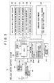
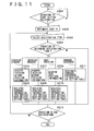
- Fig. 3 illustrates a typical structure of the keyless entry support system 3 on board the vehicle 2.
- the keyless entry support system 3 of this embodiment is mainly constituted by a communication processing block 36 connected to an antenna 37, by a central control block 20 including a CPU 21, and by a match processing block 25 connected to the central control block 20.
- the central control block 20 has under its control a vehicle body-related block 30 and onboard equipment 40.
- the communication processing block 36 communicates wirelessly with a specific remote controller 1. Data sent from the remote controller 1 and received by the antenna 37 are demodulated by the communication processing block 36. The demodulated data are forwarded illustratively to the CPU 21 of the central control block 20. Given the data from the communication processing block 36, the CPU 21 carries out necessary processes accordingly.
- the CPU 21 of the central control block 20 For data transmission from the communication processing block 36, the CPU 21 of the central control block 20 initially forwards outgoing data to the communication processing block 36 and instructs the latter to transmit the data in question. In response to the instruction, the communication processing block 36 modulates the data from the CPU 21 using a predetermined carrier and transmits the modulated data illustratively by radio waves from the antenna 37 to the remote controller 1.
- the central control block 20 controls in centralized fashion the functional operations of the keyless entry support system 3.
- the central control block 20 includes the CPU 21, a ROM 22, a RAM 23, and an NV (non-volatile)-RAM 24.
- the CPU 21 carries out diverse control processes illustratively in keeping with programs retained in the ROM 22, thus implementing the operations of the keyless entry support system 3.
- the ROM 22 holds setting data for use by the CPU 21 during the processing.
- the NV-RAM 24 may have its data inside updated under control of the CPU 21.
- the NV-RAM 24 is composed of memory elements capable of retaining what is stored thereby when power is removed.
- the NV-RAM 24 accommodates various kinds of data registered by each user in connection with relevant system operations of the keyless entry support system 3.
- the NV-RAM 24 stores table data such as an authentication table 24a and a vehicle body-related setting table 24b. Details and uses of the table data will be discussed later in more detail.
- the match processing block 25 is provided to execute the personal authentication process based on fingerprint matching.
- the remote controller 1 transmits fingerprint data detected by the fingerprint detection processing block 11 to the keyless entry support system 3 as needed. When received and acquired by the keyless entry support system 3, the fingerprint data are written by the CPU 21 to the RAM 23 for storage.
- the match processing block 25 reads the fingerprint data about the target object of authentication from the RAM 23, and checks the data against the fingerprint data previously registered in the authentication table 24a for a match. The result of the check (a match or a mismatch) is reported to the CPU 21.
- the CPU 21 If the CPU 21 is notified of a match between the fingerprint data about the authentication target object and the previously registered fingerprint data, the CPU 21 recognizes successful personal authentication. If the CPU 21 receives a notice of mismatch between the fingerprint data and the previously registered fingerprint data, then the CPU 21 finds authentication of the person to be unsuccessful.
- the match processing block 25 is furnished as a hardware functional block independent of the central control block 20.
- this is not limitative of the invention.
- the functions of the match processing block 25 may be implemented on a software basis by the CPU 21 carrying out appropriate programs.
- the operation block 26 is made up of operating elements by which to operate the keyless entry support system 3. Performing an operation on the operation block 26 causes information about the executed operation to be output to the CPU 21. Upon receipt of the operation information, the CPU 21 carries out suitable control processing accordingly so that the system 3 will function as required.
- the operation block 26 may alternatively be constituted by a remote controller and by a receiver that receives and demodulates signals sent wirelessly from the remote controller before forwarding the demodulated signals to the CPU 21.
- the above-described central control block 20 executes control to change the boarding environment of the vehicle 2 to suit the person (i.e., user) authenticated in the personal authentication process, as will be discussed later in more detail.
- the boarding environment to be changed involves two principal categories of settings: vehicle body-related settings such as the mirror positions and the seat position; and onboard equipment-related settings such as those designated by each user or established automatically as per the user's usage history regarding such devices as car audio/video equipment, a car navigation system, and other combination equipment.
- the vehicle body-related block 30 and the onboard equipment 40 have their settings changed by the CPU 21 of the central control block 20 controlling the boarding environment of the vehicle 2.
- the vehicle body-related block 30 is made up of a plurality of mechanisms associated with the vehicle body. These mechanisms function in keeping with the vehicle body-related settings constituting part of the boarding environment.
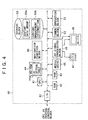
- the onboard equipment 40 is a collection of electronic devices mounted on board the vehicle 2.
- the equipment 40 in this embodiment integrates car audio/video equipment with a car navigation system, whose settings are the onboard equipment-related settings constituting another part of the boarding environment.
- the vehicle body-related block 30 of this embodiment includes a door locking/unlocking mechanism 31, an exterior mirror moving mechanism 32, an interior mirror moving mechanism 33, a seat positioning mechanism 34, and an operation support function block 35.
- the door locking/unlocking mechanism 31 is used to lock and unlock the doors of the vehicle 2.
- the external mirror moving mechanism 32 is designed to adjust electrically the orientations of the exterior mirrors such as the door and fender mirrors.
- the interior mirror moving mechanism 33 is intended to adjust electrically the orientations of the interior mirrors including the rearview mirror.
- the seat positioning mechanism 34 is provided to adjust electrically the position of the driver seat.
- the seat position should be adjustable at least in the forward and backward directions. In addition to the forward and backward directions, the seat position may be adjusted preferably in terms of backrest angle, seat height, and headrest orientation.
- the operation support function block 35 is formed by mechanisms for providing operations equivalent to those carried out by the user manipulating specific operating elements furnished in the interior of the vehicle 2. These mechanisms may include one corresponding to a trunk lever operated to open the trunk, and another representative of a so-called panic button operated by the driver signaling an emergency situation to passersby.
- the onboard equipment 40 is a combination of car audio/video equipment with a car navigation system.
- the onboard equipment 40 includes an interface 52 that ensures communication with the CPU 21 of the central control block 20 via a data bus, as illustrated.
- a CPU 41 in the onboard equipment 40 carries out necessary control processes for the equipment 40 to execute its operations.
- the processing of the CPU 41 is performed illustratively using programs retained in a ROM 42.
- the programs to be executed by the CPU 41 may alternatively be held in a storage block 50, to be described later.
- the ROM 42 accommodates setting data utilized by the CPU 41 during its processing.
- a RAM 43 is used by the CPU 41 as a work area during the processing.
- An NV-RAM 44 has various user-established data items written therein. Illustratively the NV-RAM 44 contains an AV setting table 44a as indicated. Details and uses of the AV setting table 44a will be described later.
- a media drive 45 accommodates predetermined types of media.
- the media drive 45 can read data from a recording medium loaded therein.
- the media drive 45 may further write data to a recordable medium loaded therein.
- the media drive 45 and an AV signal processing block 46 combine to provide the functions of car audio/video equipment as part of the onboard equipment 40. More specifically, when a medium carrying audio or video data is loaded into the media drive 45, the audio or video data are read from the loaded medium and fed to the AV signal processing block 46 via an internal data bus.
- the AV signal processing block 46 When supplied with the audio data, the AV signal processing block 46 subjects the data to a suitable decoding process and a digital-to-analog conversion process. The data thus processed are output from the processing block 46 to speakers 47, whereby the audio data read by the media drive 45 from the loaded medium are reproduced and output as sounds.
- the AV signal processing block 46 When supplied with the video data, the AV signal processing block 46 subjects the data to a suitable decoding process and outputs the processed data to a display unit 48 as video signals in a predetermined format.
- the display unit 48 displays pictures based on the input video signals. That is, the video data read by the media drive 45 from the loaded medium are reproduced and output as pictures.
- the media to be addressed by the media drive 45 may include, but are not limited to, disc media such as CD-ROM and DVD-ROM. Other media composed illustratively of memory elements may also be addressed by the media drive 45.
- the onboard equipment 40 of this embodiment is capable of storing a large number of audio (or video) data items in the form of a content data group 50a in a storage block 50.
- the storage block 50 should preferably be constituted by a mass storage medium such as a hard disc drive (HDD) of a required storage capacity, given the current state of the art.
- HDD hard disc drive
- the audio (or video) data When a recording medium carrying audio (or video) data is loaded into the media drive 45, the audio (or video) data are read from the loaded medium. The audio (or video) data thus retrieved are transferred to the storage block 50 via the data bus. In the storage block 50, the data are retained as content data making up the content data group 50a.
- the retrieval of content data from the media and the writing of the retrieved data to the storage block 50 may be accomplished automatically in the background under control of the CPU 41, i.e., without the user's intervention.
- the content data group 50a is managed illustratively by use of content management information 50b held in the same storage block 50.
- the content management information 50b is arranged to constitute a file system in compliance with a predetermined standard.
- the content management information 50b includes the recorded location in the storage block 50 of each of the content data items (files) as well as additional information about each content data item (file).
- the CPU 41 controls the writing and reading of content data (audio or video data) to and from the storage block 50.
- the CPU 41 executes a control process to read the content data in question from the storage block 50. More specifically, the CPU 41 references the content management information 50b forming the file system in order to read the target content data from the content data group 50a. The retrieved content data are transferred to the AV signal processing block 46 over the data bus.
- the AV signal processing block 46 decodes the data as discussed above. If the input data are audio data, the data derived from the decoding process are output as analog audio signals to the speakers 47; if the input data are audio data, the decoded data are output as video signals to the display unit 48. In this manner, the content data held in the storage block 50 can also be retrieved and output as sounds or pictures.
- the onboard equipment 40 incorporates a tuner block 53.
- the tuner block 53 illustratively receives and demodulates FM/AM broadcast waves and outputs the resulting audio data to the AV signal processing block 46. While the tuner block 53 is being selected as an active function, the AV signal processing block 46 converts the audio data coming from the tuner block 53 into analog audio signals that are sent to the speakers 47 for output as sounds.
- An operation block 51 illustratively includes a number of operating elements that are provided on the body of the onboard equipment 40. When any one of these elements is operated, the operation block 51 outputs information denoting the operation to the CPU 41. Given the operation information, the CPU 41 carries out a control process triggering the corresponding system operation.
- the operation block 51 may also be constituted by a remote controller and by a receiver that receives and demodulates signals sent wirelessly from the remote controller before forwarding the demodulated signals to the CPU 41.
- the operation block 26 furnished as part of the keyless entry support system 3 shown in Fig. 3 may take over the functions of the operation block 51 of the onboard equipment 40, thus eliminating the latter block 51.
- This alternative structure allows the user to operate the onboard equipment 40 by manipulating the operation block 26.
- a navigation function block 49 is made of components constituting a navigation system that forms part of the onboard equipment 40. More specifically, the navigation function block 49 incorporates illustratively a current position detecting system compatible with GPS (global positioning system). In this setup, map information may be acquired illustratively by the media drive 45 retrieving the information from the loaded medium. It is also possible to have the map information retained in a storage block 50, to be discussed later, for retrieval upon positioning.
- GPS global positioning system
- the media drive 45 may be used exclusively with the car audio/video devices.
- the navigation function block 49 may then possess its own media drive or HDD for accommodating map information that is reproduced for navigation use.
- the navigation function block 49 detects the vehicle's current position using the internal current position detecting system and acquires map information from the loaded medium in order to give various navigation-oriented displays illustratively on the display unit 48.
- Fig. 5 shows a user (father in this example) gripping in his hand the remote controller 1 that forms part of the inventive keyless entry system.
- the remote controller 1 that forms part of the inventive keyless entry system.
- the father is registered as a user with the keyless entry support system 3 on board the vehicle 2.
- his family members i.e., his wife, son, daughter, etc.
- Registration in this context has two meanings. On the one hand, a "registered" user means that his or her fingerprint has been recorded in advance for personal authentication purposes. On the other hand, registering, say, the father as a user with the system means that the father's fingerprint data for personal authentication are associated in storage with the setting data on the vehicle body-related block 30 and onboard equipment 40 making up the father's boarding environment for driving. What follows is a more detailed description of the steps outlined in Fig. 5, with their numbers shown encircled.
- Step 1 In the setup of Fig. 5, the user (i.e., father) operates the remote controller 1 to unlock the vehicle doors before getting in and driving the vehicle 2.
- the user operates the unlocking button 1c while pressing his fingertip onto the fingertip pressing block 1a in such a manner as to let the remote controller 1 pick up his fingerprint.
- the remote controller 1 transmits an unlock request command, together with the fingerprint data detected by the fingerprint detection processing block 11 from the user's fingertip on the fingertip pressing block 1a.
- Step 2 The keyless entry support system 3 of the vehicle 2 receives and acquires the unlock request command and fingerprint data. In response to the received command, the system 3 checks the acquired fingerprint data against the previously registered fingerprint data of legitimate users for a match. The matching process is carried out by the match processing block 25 as described above with reference to Fig. 3. Since the user (i.e., father) has his fingerprint data already registered, the check in this step results in a match. This means that the user is successfully authenticated.
- Step 3 Following the successful personal authentication, the keyless entry support system 3 unlocks illustratively the doors of the vehicle 2.
- Step 4 This and the subsequent steps constitute a procedure for establishing the boarding environment corresponding to the authenticated user based on the setting data registered beforehand. Steps 4, 5 and 6 are carried out to change the settings related to the body of the vehicle 2 as part of the boarding environment changing procedure. In step 4, the exterior mirrors are set to the father's positions.
- Step 5 In this step, the interior mirrors are set to the father's positions.
- Step 6 In this setup, the father's driver seat position is established.
- Step 7 Steps 7 through 11 are carried out to change the settings related to the onboard equipment 40 as part of the boarding environment changing procedure.
- the speakers 47 shown in Fig. 4 are assumed here to include four speaker units, two in the front (i.e., a left-hand (L) and a right-hand (R) channel speaker) and another two in the rear (a left-hand (L) and a right-hand (R) channel speaker).
- the father's right-left (L/R) balance settings about the four speaker units are established, and his front-rear (F/R) balance settings about the speakers 47 are also set up.
- Step 8 In this step, the father's volume balance settings about the speakers 47 are established.
- Step 9 Most radio tuners marketed in recent years allow users to preset the frequencies of desired radio stations. After the presetting, the user need only operate a tuner key to tune in to any favorite station.
- the tuner block 53 in the onboard equipment 40 of this embodiment in Fig. 4 also offers the radio station preset feature.
- the tuner block 53 further allows each of a plurality of users to preset separately the frequencies of his or her desired radio stations.
- the father's tuner preset specifying the selected radio station frequencies on the tuner block 53 is activated.
- Step 10 The user may change the picture quality on the display unit 48 in terms of brightness, tone and other factors to reflect his or her preferences illustratively under control of the CPU 41.
- the user-specific picture quality settings are registered in association with each of the registered users.
- the father's picture quality on the display unit 48 is established in accordance with the picture quality settings registered beforehand in association with the father.
- Step 11 The content data group 50a in the storage block 50 of the onboard equipment 40 shown in Fig. 4 is managed by use of the content management information 50b.
- the content management information 50b allows the content list registered for each user for personal authentication to manage the content data group 50a. More specifically, the content data items making up the content data group 50a are stored and managed in directories that are assigned apparently to each of the users involved.
- step 11 the father's content list is set to establish association with the corresponding content data in the storage block 50. Thereafter, content data items start getting reproduced from the storage block 50 in keeping with the father's content list.
- the sequence of reproducing content data items may reflect the reproduction frequencies recorded in that user's content list. Illustratively, content data items may be reproduced automatically in the descending order of their reproduction frequencies listed in the corresponding content list.
- the user is first authenticated when operating the remote controller 1 to unlock the vehicle doors.
- the doors are unlocked only after the user has been successfully authenticated. This feature reinforces the level of security with the keyless entry system.
- the boarding environment i.e., various settings
- the diverse vehicle settings are automatically adjusted to reflect the user's preferences.
- This embodiment by contrast, provides automatic change of the settings constituting the boarding environment for each user upon entry into the vehicle. This frees the vehicle users from the readjusting chores they went through conventionally, thereby making the preparations for driving easier and more convenient.
- steps 4 through 11 are only for illustration purposes. In practice, these steps may be modified as needed in their details and may be carried out in a sequence different from that discussed above depending on the actual use conditions.
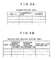
- Figs. 6A and 6B show an authentication table 24a and a vehicle body-related setting table 24b respectively. These tables list information stored in the NV-RAM 24 of the keyless entry support system 3.
- the authentication table 24a in Fig. 6A lists the information created by the users when they register for personal authentication in preparation for driving the vehicle 2.
- each user designates the start of registration by operating illustratively the operation block 26 of the keyless entry support system 3.
- the keyless entry support system 3 (CPU 21 of the central control block 20) transmits a fingerprint data request command to the remote controller 1.
- the user places his or her fingertip on the fingertip pressing block 1a of the remote controller 1 in such a manner as to let the fingerprint be detected properly.
- the remote controller 1 gets the fingerprint detection processing block 11 to pick up the user's fingerprint and generate fingerprint data accordingly.
- the fingerprint data thus generated are sent to the keyless entry support system 3.
- the keyless entry support system 3 (CPU 21 of the central control block 20) establishes a new user ID for the currently registering user.
- the system 3 causes the display unit 48 to display a user interface picture or like indications prompting the user to input a password.
- the user then enters an appropriate password by operating the operation block 26.
- the processing above provides one set of registered data: a user ID, fingerprint data, and a password.
- the keyless entry support system 3 associates these pieces of data with one another, before writing the whole data set into the authentication table 24a.
- the processing is carried out for each of a plurality of users who want to register for personal authentication.
- the vehicle body-related setting table 24b is made up of exterior mirror position information, interior mirror position information, and seat position information with regard to each user ID. That is, the table 24b contains information representing the settings of the exterior mirror moving mechanism 32, interior mirror moving mechanism 33, and seat positioning mechanism 34 constituting the boarding environment of each registered user.
- Information to be written into the vehicle body-related setting table 24b is created for each user who has registered for personal authentication and who wants to store the desired boarding environment associated with the vehicle body. For example, the user first sits on the driver seat and, in that state, adjusts the exterior mirrors, interior mirrors, and seat position in keeping with his or her preferences. The user then enters the password and performs operations to register the vehicle body settings denoting his or her optimally adjusted boarding environment.
- the CPU 21 of the central control block 20 acquires the information representative of the current exterior mirror positions, interior mirror positions, and seat position from the exterior mirror moving mechanism 32, interior mirror moving mechanism 33, and seat positioning mechanism 34 respectively. That is, the system 3 acquires the exterior mirror position information, interior mirror position information, and seat position information.
- the CPU 21 references the authentication table 24a in recognizing the user ID associated with the input password.
- the CPU 21 then associates the recognized user ID with the exterior mirror position information, interior mirror position information, and seat position information acquired earlier, and stores these pieces of information in combination into the vehicle body-related setting table 24b.
- the content management information 50b as it is structured to let the content data group 50a in the storage block 50 be managed in accordance with the content list established for each of the registered users.
- the content management information 50b held in the storage block 50 constitutes a file system that manages on a file-by-file basis the content data group 50a stored in the same storage block 50.
- individual content data items making up the content data group 50a are each stored in the storage block 50 as a file with its header area including a content ID.
- the content management information 50b includes a file system 50b-1 designed to manage the content data items.
- the file system 50b-1 retains the recorded location of each of the content data items (files) in the storage block 50, as well as additional information about each content data item (file).
- the additional information illustratively includes: the size of each content data item (file), reproduction time of each file, name of each file (i.e., title), album title of the recording medium carrying the content data item in question, names of performers associated with the content in the file, and genre of the content.
- the audio or video data stored on the hard disc drive are compressed. In such cases, the compression format and compression rate in use are also included in the additional information.
- This embodiment further includes a user content list table 50b-2 for managing content data in user-specific fashion in conjunction with the file system 50b-1.
- the user content list table 50b-2 is structured to associate a content list and a frequency list with each user ID.
- Each of the content lists in the user content list table 50b-2 is made up of content IDs which denote some content data items found in the content data group 50a and which are associated with a single user ID.
- the content IDs representative of content data items may be listed typically in the content list as shown in Fig. 8A.
- Content IDs may be written to a content list illustratively by the user manually operating the onboard equipment 40.
- this embodiment may carry out the listing process automatically. For example, when unlocking the vehicle doors by operating the remote controller 1, the user is first authenticated in the personal authentication process and is recognized as an authorized driver. The content data brought at this point into the storage block 50 are considered to belong to the currently authenticated user. The content IDs of the acquired content data items are then written automatically to the content list associated with the user ID of the user in question.
- Each of the frequency lists in the user content list table 50b-2 provides information designed to manage user-specific content data items in each content list in a manner reflecting how many times each of the data items has been reproduced so far by the user in question. As depicted in Fig. 8B, each frequency list associates each content ID with the number of times the corresponding data item has been reproduced. The content IDs are then managed in the descending order of the frequencies of their corresponding content data items.
- the user content list table 50b-2 thus makes it possible to structure each of the user-specific content lists in a manner reflecting how many times each of the listed content data items has been reproduced.
- the listed content data items can be reproduced in the descending order of their past reproduction frequencies.
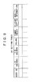
- the AV setting table 44a is a table that is referenced in the above-described steps 7 through 9 of Fig. 5 carried out to change the onboard equipment-related settings.
- the AV setting table 44a is structured to accommodate such information as the L/R balance, F/R balance, volume, tuner preset, and picture quality setting information in conjunction with each user ID.
- the L/R balance and F/R balance are information constituted by the left-right and front-rear balance settings of sound output from the speakers 47.
- the volume is information about the settings of sound volume from the speakers 47.
- the tuner preset is information about at least one selected radio station frequency to be preset on the tuner block 53.
- the picture quality setting information is information formed by the settings of brightness, sharpness, tone, and other parameters for adjusting picture quality on the display unit 48.
- Described below are typical processing operations carried out by the keyless entry system embodying this invention, the description being based on the above-mentioned structure of the embodiment as well as on the data structure examples for use therewith.
- the processing in Fig. 10 is executed by the keyless entry support system 3 on board the vehicle 2 and by the remote controller 1 working in collaboration. More specifically, the processing on the part of the keyless entry support system 3 is carried out by the CPU 21 of the central control system 20 (see Fig. 3), and the processing on the part of the remote controller 1 is performed by the CPU 12 (see Fig. 2).
- step S101 the CPU 21 of the keyless entry support system 3 waits for a user to perform an operation to start registering for personal authentication.
- the registration starting operation is performed on the operation block 26 of the keyless entry support system 3, information denoting the operation is input to the CPU 21.
- the information input brings about an affirmative result of the check in step S101, which leads to step S102.
- step S102 the CPU 21 transmits a fingerprint data request command to the remote controller 1.
- step S201 the CPU 12 of the remote controller 1 waits for the fingerprint data request command to come in. Upon verifying receipt of the request command, the CPU 12 goes to step S202. At this point, as discussed above, the user presses his or her fingertip onto the fingertip pressing block 1a of the remote controller 1. The fingerprint detection processing block 11 of the remote controller 1 picks up the user's fingerprint and generates fingerprint data accordingly.
- step S202 the fingerprint data thus generated are transmitted from the CPU 12 to the keyless entry support system 3.
- step S103 the CPU 21 of the keyless entry support system 3 waits for the fingerprint data to arrive.
- the CPU 21 goes to step S104.
- step S104 the CPU 21 causes the display unit 48 illustratively to display a user interface picture prompting the user to input a password.
- the CPU 21 remains ready to execute a process for retaining a password that will be entered by the user through the operation block 26.
- step S105 With the password input, step S105 is reached.
- the CPU 21 establishes a new user ID corresponding to the ongoing registration.
- the CPU 21 then stores into an authentication table 24a the newly established user ID in association with the fingerprint data received in step S103 as well as the password entered in step S104. This creates one (more) authentication table 24a having relevant information corresponding to one (more) user ID.
- the keyless entry support system 3 may accept input of information other than the password as part of the processing in Fig. 10.
- the user may be allowed to enter his or her own user name.
- the father may input a desired user name like "Dad" in characters when registering as a legitimate user.
- the user name may be registered in association with the user ID, fingerprint data, and password.
- the associative registration of the user name allows the system to present an appropriate user interface corresponding to each specific user name. This helps the user subsequently to proceed more easily with an application for establishing desired settings.
- a desired boarding environment (settings) that is to be invoked upon subsequent use of the vehicle.
- the processing operations for boarding environment registration are described below with reference to Fig. 11.
- the processing in Fig. 11 is carried out by the CPU 21 of the central control block 20 in the keyless entry support system 3.
- step S301 the CPU 21 waits for an operation to start registering the settings (i.e., boarding environment).
- the settings i.e., boarding environment.
- the operation block 26 is operated by the user starting to register preferred settings, information denoting the operation is input to the CPU 21.
- the CPU 21 goes to step S302.
- step S302 the CPU 21 causes the display unit 48 illustratively to display a user interface picture in which the currently registering user identifies himself or herself.
- the user interface pictures may be arranged for the user's identification based on the above-mentioned user name.
- the CPU 21 designates a suitable user ID.
- the CPU 21 goes to step S303 and causes a user interface picture in which to select a registration item to be displayed (i.e., registration item selection picture).
- registration item selection picture the user selects a desired registration item by operating the operation block 26.
- Step S303 is repeated until a registration item determining operation is performed in step S304 and a registration ending operation is carried out in step S312, as will be described later.
- the user may selectively change the registration item before carrying out the operation item determining operation.
- step S304 When the registration item determining operation is found executed in step S304, the CPU 21 goes to one of steps S305, S307, S308, and S311 depending on the selected registration item.
- step S305 the CPU 21 acquires the current exterior mirror position information from the exterior mirror moving mechanism 32 in the vehicle body-related block 30.
- step S306 the CPU 21 stores into the vehicle body-related setting table 24b the exterior mirror position information in association with the user ID designated in step S302 earlier.
- step S307 the CPU 21 acquires the current interior mirror position information from the interior mirror moving mechanism 33 in the vehicle body-related block 30.
- step S308 the CPU 21 stores into the vehicle body-related setting table 24b the interior mirror position information in association with the same user ID designated in step S302.
- step S309 the CPU 21 acquires the current seat position information from the seat positioning mechanism 34.
- step S310 the CPU 21 stores into the vehicle body-related setting table 24b the seat position information in association with the same user ID.
- the vehicle body-related setting table 24b is set to accommodate the setting information related to the vehicle body (i.e., exterior mirror position information, interior mirror position information, and seat position information) associated with a single user ID.
- step S311 is reached. Where the registration item is the AV setting item of the onboard equipment 40, necessary information needs to be written to the AV setting table 44a of the onboard equipment 40.
- the CPU 21 transmits a command to the CPU 41 of the onboard equipment 40 instructing the latter to write the setting information into the AV setting table 44a. The command is transmitted along with the user ID designated in step S302 earlier.
- the CPU 41 of the onboard equipment 40 performs processing, not shown in any flowchart, in response to the above instruction that the setting information is to be written to the AV setting table 44a.
- the processing roughly proceeds as follows:
- the CPU 41 acquires the current L/R balance, F/R balance, and volume settings illustratively from the AV signal processing block 46.
- the CPU 41 also acquires the preset data about the currently selected radio station frequencies on the tuner block 53.
- the CPU 41 further acquires the settings for adjusting the current picture quality on the display unit 48.
- the acquired information i.e., L/R balance, F/R balance, volume, and tuner preset information, as well as picture quality setting information
- the acquired information is stored into the AV setting table 44a in association with the user ID received earlier along with the command.
- the setting information corresponding to each user ID is written to and retained by the AV setting table 44a shown in Fig. 9.
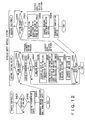
- Fig. 12 Described below with reference to Fig. 12 is how the keyless entry system works in response to the operation carried out on the remote controller 1 to unlock the vehicle doors.
- the processing in Fig. 12 is executed by the CPU 12 of the remote controller 1, as well as by the CPU 21 of the central control block 20 and by the CPU 41 of the onboard equipment 40 working in collaboration in the keyless entry support system 3.
- step S401 the CPU 12 of the remote controller 1 waits for an operation to be performed to unlock the doors. More specifically, the CPU 12 waits for the user to operate the unlocking button 1c on the remote controller 1. When the unlocking button 1c is found to be operated, step S402 is reached.
- step S402 the CPU 12 acquires fingerprint data. Specifically, upon operating the unlocking button 1c of the remote controller 1, the user is expected to press his or her fingertip onto the fingertip pressing block 1a in a manner permitting fingertip detection to take place. In turn, the fingerprint detection processing block 11 detects the user's fingerprint and generates fingerprint data accordingly. The CPU 12 writes the fingerprint data illustratively to the RAM 14 for storage, thereby acquiring the fingerprint data.
- step S403 the CPU 12 transmits the acquired fingerprint data to the keyless entry support system 3 together with an unlock request command.
- step S501 the CPU 21 of the keyless entry support system 3 waits for the unlock request command to come in.
- the CPU 21 goes to step S502 and subsequent steps.
- Steps S502 and S503 constitute a process for personal authentication based on a fingerprint match.
- step S502 which is executed for fingerprint matching, the CPU 21 transfers the received fingerprint data to the match processing block 25 together with the unlock request command.
- the CPU 21 also transfers successively the fingerprint data items registered in the authentication table 24a to the match processing block 25.
- the match processing block 25 checks the received fingerprint data against each of the registered fingerprint data items for a match and outputs the result of the check.
- step S503 the CPU 21 receives the result of the matching done by the match processing block 25, to see if there is a match between the received fingerprint data and the registered fingerprint data.
- step S503 If in step S503 no match is detected between the received fingerprint data and the registered fingerprint data, that means the personal authentication has failed. In that case, the processing is brought to an end and no further step is carried out. In other words, the system determines that an unauthorized person has tried to unlock the vehicle doors fraudulently by operating the remote controller 1. The attempt to unlock the doors is then rejected and no settings of the boarding environment are changed.
- step S503 If in step S503 a match is detected between the received fingerprint data and the registered fingerprint data, then step S504 and subsequent steps are reached and carried out.
- step S504 the CPU 21 causes the door locking/unlocking mechanism 31 of the vehicle body-related block 30 to unlock the doors of the vehicle 2.
- Steps S505 through S507 constitute a process for changing the settings of the vehicle body.
- the CPU 21 references the authentication table 24a to recognize the user ID associated with the previously registered fingerprint data item that matches the received fingerprint data. With the user ID recognized, step S505 is followed by step S506.
- step S506 the CPU 21 acquires from the vehicle body-related setting table 24b the vehicle body-related setting information (i.e., exterior mirror position information, interior mirror position information, and seat position information) associated with the user ID recognized in step S505 above.
- vehicle body-related setting information i.e., exterior mirror position information, interior mirror position information, and seat position information
- step S507 the CPU 21 changes the relevant settings of the vehicle body based on the exterior mirror position information, interior mirror position information, and seat position information acquired in step S506 earlier. More specifically, the exterior mirror moving mechanism 32 is controlled so as to attain the exterior mirror orientation designated by the exterior mirror position information; the interior mirror moving mechanism 33 is controlled to reach the interior mirror orientation specified by the interior mirror position information; and the seat positioning mechanism 34 is controlled to obtain the seat position reflecting the seat position information.
- step S507 when carried out, complete the change of the settings related to the vehicle body.
- the change of the vehicle body settings is followed by the change of the settings on the onboard equipment 40.
- the latter change is performed by the CPU 41 in the onboard equipment 40.
- step S508 the CPU 21 of the central control block 20 transmits a setting change request command along with the user ID to the CPU 41 of the onboard equipment 40, the command instructing the CPU 41 to change the settings of the onboard equipment 40.
- the user ID sent at this point to the CPU 41 is the user ID recognized in step S505 earlier.
- step S601 the CPU 41 of the onboard equipment 40 waits for the setting change request command to come in. Upon verifying receipt of the command, the CPU 41 goes to step S602 and subsequent steps.
- Steps S602 and S603 constitute a process for changing the onboard equipment settings.
- the CPU 41 acquires from the AV setting table 44a in the NV-RAM 44 the AV setting information corresponding to the user ID received earlier together with the setting request command. That is, the CPU 41 obtains the L/R balance, F/R balance, volume, and tuner preset information as well as the picture quality setting information, which have been stored in association with the received user ID.
- step 5603 the CPU 41 carries out a control process to establish the AV setting environment designated by the setting information acquired in step S602 above. More specifically, steps 7 through 10 outlined in Fig. 5 are carried out.
- the CPU 41 controls an audio signal output circuit of the AV signal processing block 46 so as to attain the L/R audio balance, F/R audio balance, and volume level designated by the L/R balance, F/R balance, and volume settings respectively. Furthermore, the CPU 41 controls a display circuit of the display unit 48 to bring about the degree of picture quality specified by the picture quality setting information, as discussed earlier in connection with steps 7 through 10 in Fig. 5.
- step S603 which corresponds to step 11 in Fig. 5, the CPU 41 performs a control process to change the content list of the content data to be reproduced from the storage block 50. More specifically, the CPU 41 references the user content list table 50b-2 in the content management information 50b to acquire the content list and frequency list corresponding to the user ID received along with the setting change request command. Based on the content list and frequency list thus acquired, the CPU 41 changes the list of content items to be output and reproduced from the storage block 50. Illustratively, the content items included in the acquired content list are established as the content to be output and reproduced from the storage block 50. The order in which the content items are to be reproduced can be determined in accordance with the frequency list.
- step S604 is reached in which the CPU 41 transmits a setting change completion notice to the CPU 21 of the central control block 20, notifying the latter that the change of the settings related to the onboard equipment 40 is now complete.
- the CPU 21 of the central control block 20 receives the notice in step S509. The CPU 21 then brings the processing to an end.
- the keyless entry support system 3 has two CPUs, i.e., CPU 21 of the central control block 20 and CPU 41 of the onboard equipment 40, and that these two CPUs work in collaboration to provide the necessary processing operations.
- an alternative set of specifications for the keyless entry support system 3 may let the CPU 21 of the central control block 20 take over all control operations including those of the CPU 41 of the onboard equipment 40, thereby eliminating the CPU 41.
- the programs for implementing the processes outlined in the flowcharts of Figs. 10 through 12 are stored beforehand in a plurality of locations: in the ROM 13 of the remote controller 1, and in the ROMs 22 and 42 of the central control block 20 and onboard equipment 40 respectively in the keyless entry support system 3.
- programs may be offered as package software recorded on a suitable medium which is loaded into the media drive 45 of the onboard equipment 40 for eventual program retrieval and execution.
- the keyless entry support system 3 causes the media drive 45 to read the programs from the loaded medium and write the retrieved programs to an appropriate ROM for installation.
- the personal authentication process starts with the remote controller 1 picking up the detection target object (i.e., user's fingerprint) and obtaining detection information (i.e., fingerprint data) accordingly.
- the detection information thus acquired is transmitted to and received by the keyless entry support system 3 which utilizes the received fingerprint data as a basis for personal authentication. That is, the personal authentication process of the keyless entry system is carried out primarily by the keyless entry support system 3 on the side of the vehicle 2; the remote controller 1 is used merely to execute detection of the target object.
- the remote controller 1 may be designed to take over the personal authentication process. More specifically, the remote controller 1 may pick up the user's fingerprint, acquire fingerprint data accordingly, and proceed with the personal authentication process based on the acquired fingerprint data. Once the user is successfully authenticated, the remote controller 1 may transmit to the keyless entry support system 3 commands instructing the latter to unlock the vehicle doors and change the settings of the boarding environment to suit the user in question. If the authentication is unsuccessful, the remote controller 1 will not send the commands to the keyless entry support system 3.
- the remote controller 1 take over the personal authentication process illustratively involves storing the authentication table 24a into the ROM 13 of the remote controller 1 and getting the CPU 11 to perform the authentication based on the authentication table 24a and the detected fingerprint data.
- the settings of the onboard equipment may also be varied in a manner other than that discussed above.
- the changeable settings of the onboard equipment are not limited to the audio/video settings alone.
- the settings of the navigation function may be modified as well.
- the navigation system has its own information acquired and registered in user-specific fashion, such as driving history and checked destinations of each user. These items of information may also be changed as part of the onboard equipment settings every time a different user gains access to the vehicle. This provides additional convenience to the navigation feature of the vehicle.
- the keyless entry system of the vehicle is combined with the personal authentication system to make up a keyless entry system that provides reinforced security.
- a plurality of users are allowed to register as legitimate users with the system. Each of these users is identified upon entry into the vehicle, the identification being utilized upon unlocking of the vehicle doors as a basis for changing the current boarding environment, i.e., for bringing into effect the boarding environment settings registered in advance for the identified user.
- the feature above supplements the keyless entry system based on personal authentication with the capability of automatically changing the boarding environment of the vehicle depending on the user wishing to drive the vehicle.
- the registered users are thus offered greater ease of use and more convenience than ever before when getting into the vehicle equipped with the inventive keyless entry system.
Landscapes
- Engineering & Computer Science (AREA)
- Mechanical Engineering (AREA)
- Human Computer Interaction (AREA)
- Lock And Its Accessories (AREA)
- Rear-View Mirror Devices That Are Mounted On The Exterior Of The Vehicle (AREA)
Applications Claiming Priority (2)
| Application Number | Priority Date | Filing Date | Title |
|---|---|---|---|
| JP2002368103A JP2004196154A (ja) | 2002-12-19 | 2002-12-19 | 搭乗環境制御システム、搭乗環境制御装置、搭乗環境制御方法 |
| JP2002368103 | 2002-12-19 |
Publications (3)
| Publication Number | Publication Date |
|---|---|
| EP1431140A2 true EP1431140A2 (de) | 2004-06-23 |
| EP1431140A3 EP1431140A3 (de) | 2004-07-07 |
| EP1431140B1 EP1431140B1 (de) | 2008-03-19 |
Family
ID=32376292
Family Applications (1)
| Application Number | Title | Priority Date | Filing Date |
|---|---|---|---|
| EP20030257968 Expired - Lifetime EP1431140B1 (de) | 2002-12-19 | 2003-12-17 | Bordumgebungs-Steuersystem, Bordumgebungs-Steuervorrichtung, und Bordumgebungs-Steuermethode |
Country Status (4)
| Country | Link |
|---|---|
| US (1) | US7301441B2 (de) |
| EP (1) | EP1431140B1 (de) |
| JP (1) | JP2004196154A (de) |
| DE (1) | DE60319793T2 (de) |
Cited By (4)
| Publication number | Priority date | Publication date | Assignee | Title |
|---|---|---|---|---|
| EP1674323A1 (de) * | 2003-09-26 | 2006-06-28 | Nippon Seiki Co., Ltd. | Anzeigevorrichtung für fahrzeug |
| EP2347569A1 (de) * | 2008-10-17 | 2011-07-27 | Toyota Motor Sales, U.S.A., Inc. | Biometrische systeme und verfahren für ein fahrzeug |
| EP2900533A4 (de) * | 2012-09-28 | 2016-08-03 | Intel Corp | Mobilvorrichtung und schlüsselanhängerpaarung für mehrfaktorsicherheit |
| CN111791830A (zh) * | 2019-04-08 | 2020-10-20 | 联合汽车电子有限公司 | 蓝牙信号识别方法与蓝牙信号识别系统 |
Families Citing this family (76)
| Publication number | Priority date | Publication date | Assignee | Title |
|---|---|---|---|---|
| JP2001093226A (ja) * | 1999-09-21 | 2001-04-06 | Sony Corp | 情報通信システムおよび方法、ならびに、情報通信装置および方法 |
| US7306283B2 (en) | 2002-11-21 | 2007-12-11 | W.E.T. Automotive Systems Ag | Heater for an automotive vehicle and method of forming same |
| JP2006521724A (ja) * | 2003-01-28 | 2006-09-21 | セルポート システムズ インコーポレイテッド | セキュア・テレマティクス |
| US7050795B2 (en) * | 2004-06-24 | 2006-05-23 | Denso International America, Inc. | System for programming customizable vehicle features |
| US6970098B1 (en) | 2004-08-16 | 2005-11-29 | Microsoft Corporation | Smart biometric remote control with telephony integration method |
| JP4541857B2 (ja) * | 2004-11-30 | 2010-09-08 | エクジット株式会社 | キーレスエントリーシステム |
| CN101189405B (zh) * | 2005-05-31 | 2012-02-01 | 三洋电机株式会社 | 电子式钥匙系统及使用其的二轮机动车 |
| US20060294393A1 (en) * | 2005-06-24 | 2006-12-28 | Mc Call Clark E | Remote biometric registration for vehicles |
| JP2007013749A (ja) * | 2005-07-01 | 2007-01-18 | Hitachi Ltd | 運輸機器の遠隔制御システム |
| US10009956B1 (en) * | 2017-09-02 | 2018-06-26 | Kamilo Feher | OFDM, 3G and 4G cellular multimode systems and wireless mobile networks |
| JP4554473B2 (ja) * | 2005-08-26 | 2010-09-29 | パナソニック株式会社 | コンテンツサーバ装置 |
| JP2007099157A (ja) * | 2005-10-06 | 2007-04-19 | Calsonic Kansei Corp | 車用シート装置 |
| JP5001028B2 (ja) * | 2007-03-02 | 2012-08-15 | 株式会社デンソー | 運転環境設定システム、車載装置及び車載装置用プログラム |
| US8011593B2 (en) * | 2007-03-15 | 2011-09-06 | Joseph Frank Preta | Smart apparatus for making secure transactions |
| US7979177B2 (en) * | 2007-04-30 | 2011-07-12 | Ford Motor Company | System and method for updating vehicle computing platform configuration information |
| CA2592981A1 (en) * | 2007-07-05 | 2009-01-05 | Fortin Auto Radio Inc. | Insulating control device and method for vehicle proximity remote |
| US8618908B2 (en) * | 2007-11-20 | 2013-12-31 | Cisco Technology, Inc. | Providing an endpoint access to a locked target |
| JP4561848B2 (ja) * | 2008-03-06 | 2010-10-13 | 株式会社デンソー | 車両ドア制御システム |
| US8825222B2 (en) * | 2009-02-27 | 2014-09-02 | Toyota Motor Engineering & Manufacturing North America, Inc. | Remote management of vehicle settings |
| US9639688B2 (en) | 2010-05-27 | 2017-05-02 | Ford Global Technologies, Llc | Methods and systems for implementing and enforcing security and resource policies for a vehicle |
| US8544942B2 (en) | 2010-05-27 | 2013-10-01 | W.E.T. Automotive Systems, Ltd. | Heater for an automotive vehicle and method of forming same |
| US8725330B2 (en) | 2010-06-02 | 2014-05-13 | Bryan Marc Failing | Increasing vehicle security |
| WO2012001771A1 (ja) * | 2010-06-29 | 2012-01-05 | トヨタ自動車株式会社 | 制御装置 |
| DE102011114949A1 (de) | 2010-10-19 | 2012-04-19 | W.E.T. Automotive Systems Ag | Elektrischer Leiter |
| US9452735B2 (en) | 2011-02-10 | 2016-09-27 | Ford Global Technologies, Llc | System and method for controlling a restricted mode in a vehicle |
| US8522320B2 (en) | 2011-04-01 | 2013-08-27 | Ford Global Technologies, Llc | Methods and systems for authenticating one or more users of a vehicle communications and information system |
| DE102012000977A1 (de) | 2011-04-06 | 2012-10-11 | W.E.T. Automotive Systems Ag | Heizeinrichtung für komplex geformte Oberflächen |
| US8788113B2 (en) | 2011-06-13 | 2014-07-22 | Ford Global Technologies, Llc | Vehicle driver advisory system and method |
| US10097993B2 (en) | 2011-07-25 | 2018-10-09 | Ford Global Technologies, Llc | Method and apparatus for remote authentication |
| US8849519B2 (en) | 2011-08-09 | 2014-09-30 | Ford Global Technologies, Llc | Method and apparatus for vehicle hardware theft prevention |
| DE102011121979A1 (de) | 2011-09-14 | 2012-11-22 | W.E.T. Automotive Systems Ag | Temperier-Einrichtung |
| KR20130065104A (ko) * | 2011-12-09 | 2013-06-19 | 현대자동차주식회사 | 차량 설정 공유 시스템 |
| US10201039B2 (en) | 2012-01-20 | 2019-02-05 | Gentherm Gmbh | Felt heater and method of making |
| JP5906865B2 (ja) * | 2012-03-22 | 2016-04-20 | アイシン精機株式会社 | 車両用シート装置 |
| US20130293347A1 (en) * | 2012-05-01 | 2013-11-07 | William Barnes | Keyless vehicle entry device |
| US9569403B2 (en) * | 2012-05-03 | 2017-02-14 | Ford Global Technologies, Llc | Methods and systems for authenticating one or more users of a vehicle communications and information system |
| DE202013003491U1 (de) | 2012-06-18 | 2013-09-20 | W.E.T. Automotive Systems Ag | Flächengebilde mit elektrischer Funktion |
| DE102012017047A1 (de) | 2012-08-29 | 2014-03-06 | W.E.T. Automotive Systems Ag | Elektrische Heizeinrichtung |
| US9002586B2 (en) * | 2012-12-03 | 2015-04-07 | Honda Motor Co., Ltd. | Integrated biometric switch |
| KR101491220B1 (ko) | 2012-12-18 | 2015-02-06 | 현대자동차주식회사 | 차량 모듈의 자동 실행 방법 및 이러한 방법을 수행하는 장치 |
| DE102012024903A1 (de) | 2012-12-20 | 2014-06-26 | W.E.T. Automotive Systems Ag | Flächengebilde mit elektrischen Funktionselementen |
| US8866604B2 (en) | 2013-02-14 | 2014-10-21 | Ford Global Technologies, Llc | System and method for a human machine interface |
| US9688246B2 (en) | 2013-02-25 | 2017-06-27 | Ford Global Technologies, Llc | Method and apparatus for in-vehicle alarm activation and response handling |
| US8947221B2 (en) | 2013-02-26 | 2015-02-03 | Ford Global Technologies, Llc | Method and apparatus for tracking device connection and state change |
| US9221405B2 (en) * | 2013-03-04 | 2015-12-29 | Donnell A. Davis | Multi-function electronic display license plate system |
| US9141583B2 (en) | 2013-03-13 | 2015-09-22 | Ford Global Technologies, Llc | Method and system for supervising information communication based on occupant and vehicle environment |
| US9002536B2 (en) | 2013-03-14 | 2015-04-07 | Ford Global Technologies, Llc | Key fob security copy to a mobile phone |
| CN105165112B (zh) | 2013-05-02 | 2018-11-02 | 捷温加拿大有限公司 | 防液性加热元件 |
| US9911320B2 (en) | 2013-08-02 | 2018-03-06 | Vermeer Manufacturing Company | Remote control system |
| US9807172B2 (en) * | 2013-10-18 | 2017-10-31 | At&T Intellectual Property I, L.P. | Mobile device intermediary for vehicle adaptation |
| US9203843B2 (en) | 2013-11-08 | 2015-12-01 | At&T Mobility Ii Llc | Mobile device enabled tiered data exchange via a vehicle |
| EP3230132A4 (de) * | 2014-12-12 | 2018-08-01 | Romesh Wadhwani | Smartkey-vorrichtungen, verfahren und systeme |
| DE102015203661A1 (de) * | 2015-03-02 | 2016-09-08 | Volkswagen Aktiengesellschaft | Funktionsabschaltung für ein Fahrzeugzugangssystem |
| US10249123B2 (en) | 2015-04-09 | 2019-04-02 | Ford Global Technologies, Llc | Systems and methods for mobile phone key fob management |
| US11014536B2 (en) * | 2015-04-13 | 2021-05-25 | Ford Global Technologies, Llc | Vehicle controller delivery mode |
| JP6494108B2 (ja) * | 2015-09-09 | 2019-04-03 | 株式会社東海理化電機製作所 | 判定装置 |
| JP6489695B2 (ja) * | 2015-09-09 | 2019-03-27 | 株式会社東海理化電機製作所 | 判定装置 |
| JP6534586B2 (ja) * | 2015-09-09 | 2019-06-26 | 株式会社東海理化電機製作所 | 判定装置 |
| JP6494109B2 (ja) * | 2015-09-09 | 2019-04-03 | 株式会社東海理化電機製作所 | 判定装置 |
| JP6494107B2 (ja) * | 2015-09-09 | 2019-04-03 | 株式会社東海理化電機製作所 | 判定装置 |
| US10239489B2 (en) * | 2015-09-11 | 2019-03-26 | Dura Operating, Llc | Vehicle access system with inadvertent actuation control |
| JP6706896B2 (ja) * | 2015-10-07 | 2020-06-10 | 株式会社東海理化電機製作所 | 操作者判定装置 |
| JP6584904B2 (ja) * | 2015-10-07 | 2019-10-02 | 株式会社東海理化電機製作所 | 操作者判定装置 |
| JP6599198B2 (ja) * | 2015-10-07 | 2019-10-30 | 株式会社東海理化電機製作所 | 操作者判定装置 |
| US9978278B2 (en) | 2015-11-27 | 2018-05-22 | Bragi GmbH | Vehicle to vehicle communications using ear pieces |
| US10040423B2 (en) * | 2015-11-27 | 2018-08-07 | Bragi GmbH | Vehicle with wearable for identifying one or more vehicle occupants |
| US10099636B2 (en) * | 2015-11-27 | 2018-10-16 | Bragi GmbH | System and method for determining a user role and user settings associated with a vehicle |
| US9944295B2 (en) | 2015-11-27 | 2018-04-17 | Bragi GmbH | Vehicle with wearable for identifying role of one or more users and adjustment of user settings |
| US10104460B2 (en) | 2015-11-27 | 2018-10-16 | Bragi GmbH | Vehicle with interaction between entertainment systems and wearable devices |
| WO2018085104A1 (en) | 2016-11-01 | 2018-05-11 | Gentherm Incorporated | Flexible heater and method of integration |
| KR102642241B1 (ko) * | 2016-11-14 | 2024-03-04 | 현대자동차주식회사 | 차량 및 그 제어방법 |
| DE102017001097A1 (de) | 2017-02-07 | 2018-08-09 | Gentherm Gmbh | Elektrisch leitfähige Folie |
| CN108608088B (zh) * | 2018-07-13 | 2024-06-21 | 广西广协智能科技有限公司 | 一种冷藏回温锡膏柜 |
| KR102695209B1 (ko) * | 2019-03-21 | 2024-08-13 | 현대자동차주식회사 | 식별 디바이스를 활용한 이동체 제어 방법 및 장치 |
| JP2020172220A (ja) * | 2019-04-12 | 2020-10-22 | 株式会社東海理化電機製作所 | 電子機器 |
| DE102021206838A1 (de) | 2021-06-30 | 2023-01-05 | Volkswagen Aktiengesellschaft | Verfahren zum Einstellen einer Authentifizierungsmethode an einer elektronischen Vorrichtung und elektronische Vorrichtung |
Citations (5)
| Publication number | Priority date | Publication date | Assignee | Title |
|---|---|---|---|---|
| DE19801119C1 (de) * | 1998-01-15 | 1999-09-23 | Kostal Leopold Gmbh & Co Kg | Nutzungsberechtigungssystem |
| EP1113405A2 (de) * | 1999-12-30 | 2001-07-04 | STMicroelectronics, Inc. | Steuerschnittstelle mit Verwendung eines Fingerabdruckeingabesystems |
| DE10048394A1 (de) * | 2000-03-21 | 2001-10-25 | Mitsubishi Electric Corp | Fahrzeugschlüsselsystem |
| DE10042055A1 (de) * | 2000-08-26 | 2002-03-21 | Audi Ag | Personalisierungsvorrichtung und Personalisierungsverfahren zur benutzerabhängigen Einstellung von Parameterwerten |
| DE10103044A1 (de) * | 2001-01-24 | 2002-07-25 | Bosch Gmbh Robert | Vorrichtung zur benutzerspezifischen Aktivierung von Fahrzeugfunktionen |
Family Cites Families (19)
| Publication number | Priority date | Publication date | Assignee | Title |
|---|---|---|---|---|
| JPS626048A (ja) | 1985-06-29 | 1987-01-13 | 三晃金属工業株式会社 | 外囲体 |
| JPH0195955A (ja) | 1987-10-09 | 1989-04-14 | Mazda Motor Corp | 車両用電装品制御装置 |
| US6140938A (en) * | 1995-04-14 | 2000-10-31 | Flick; Kenneth E. | Remote control system suitable for a vehicle and having remote transmitter verification |
| US5808374A (en) * | 1997-03-25 | 1998-09-15 | Ut Automotive Dearborn, Inc. | Driver interface system for vehicle control parameters and easy to utilize switches |
| JPH1193478A (ja) | 1997-09-18 | 1999-04-06 | Nissan Motor Co Ltd | キーレスエントリシステム |
| US6100811A (en) | 1997-12-22 | 2000-08-08 | Trw Inc. | Fingerprint actuation of customized vehicle features |
| US6144114A (en) * | 1998-03-25 | 2000-11-07 | Lear Automotive Dearborn, Inc. | Auto PC wallet PC faceplate |
| JP2000016203A (ja) | 1998-07-03 | 2000-01-18 | Denso Corp | 車両通信システム |
| US6282475B1 (en) * | 1999-09-20 | 2001-08-28 | Valdemar L. Washington | System for automatically adjustable devices in an automotive vehicle |
| JP4548883B2 (ja) | 1999-11-30 | 2010-09-22 | 富士通テン株式会社 | リモートコントロールシステム、及び受信機 |
| JP2001262890A (ja) * | 2000-03-21 | 2001-09-26 | Mitsubishi Electric Corp | 車両キーシステム |
| JP4499278B2 (ja) | 2000-12-22 | 2010-07-07 | ソニー株式会社 | 車両検索装置及び車両検索方法 |
| US20030157920A1 (en) * | 2000-12-27 | 2003-08-21 | Constance Liu | Radio that remembers adjustment settings |
| JP2002331885A (ja) | 2001-05-11 | 2002-11-19 | Koyo Seiko Co Ltd | 情報記録媒体、運転管理装置および運転管理システム |
| US20020197976A1 (en) * | 2001-06-22 | 2002-12-26 | Jonathan Liu | Vehicle customized feature activation system |
| US6775603B2 (en) * | 2001-10-18 | 2004-08-10 | Ford Motor Company | Method and system for maintaining personalization of user adjustable features |
| US6785595B2 (en) * | 2002-02-13 | 2004-08-31 | Honda Giken Kogyo Kabushiki Kaisha | Electronic control system for vehicle accessory devices |
| US7552140B2 (en) * | 2002-07-25 | 2009-06-23 | Temic Automotive Of North America, Inc. | Smart owner's manual |
| US6718240B1 (en) * | 2002-08-28 | 2004-04-06 | Honda Giken Kogyo Kabushiki Kaisha | Remote keyless entry system |
-
2002
- 2002-12-19 JP JP2002368103A patent/JP2004196154A/ja active Pending
-
2003
- 2003-10-29 US US10/696,024 patent/US7301441B2/en not_active Expired - Lifetime
- 2003-12-17 DE DE2003619793 patent/DE60319793T2/de not_active Expired - Lifetime
- 2003-12-17 EP EP20030257968 patent/EP1431140B1/de not_active Expired - Lifetime
Patent Citations (5)
| Publication number | Priority date | Publication date | Assignee | Title |
|---|---|---|---|---|
| DE19801119C1 (de) * | 1998-01-15 | 1999-09-23 | Kostal Leopold Gmbh & Co Kg | Nutzungsberechtigungssystem |
| EP1113405A2 (de) * | 1999-12-30 | 2001-07-04 | STMicroelectronics, Inc. | Steuerschnittstelle mit Verwendung eines Fingerabdruckeingabesystems |
| DE10048394A1 (de) * | 2000-03-21 | 2001-10-25 | Mitsubishi Electric Corp | Fahrzeugschlüsselsystem |
| DE10042055A1 (de) * | 2000-08-26 | 2002-03-21 | Audi Ag | Personalisierungsvorrichtung und Personalisierungsverfahren zur benutzerabhängigen Einstellung von Parameterwerten |
| DE10103044A1 (de) * | 2001-01-24 | 2002-07-25 | Bosch Gmbh Robert | Vorrichtung zur benutzerspezifischen Aktivierung von Fahrzeugfunktionen |
Cited By (7)
| Publication number | Priority date | Publication date | Assignee | Title |
|---|---|---|---|---|
| EP1674323A1 (de) * | 2003-09-26 | 2006-06-28 | Nippon Seiki Co., Ltd. | Anzeigevorrichtung für fahrzeug |
| EP1674323A4 (de) * | 2003-09-26 | 2008-04-16 | Nippon Seiki Co Ltd | Anzeigevorrichtung für fahrzeug |
| EP2347569A1 (de) * | 2008-10-17 | 2011-07-27 | Toyota Motor Sales, U.S.A., Inc. | Biometrische systeme und verfahren für ein fahrzeug |
| EP2428409A1 (de) * | 2008-10-17 | 2012-03-14 | Toyota Motor Sales, U.S.A., Inc. | Biometrisches System und Verfahren für ein Kraftfahrzeug |
| EP2347569A4 (de) * | 2008-10-17 | 2012-03-14 | Toyota Motor Sales Usa Inc | Biometrische systeme und verfahren für ein fahrzeug |
| EP2900533A4 (de) * | 2012-09-28 | 2016-08-03 | Intel Corp | Mobilvorrichtung und schlüsselanhängerpaarung für mehrfaktorsicherheit |
| CN111791830A (zh) * | 2019-04-08 | 2020-10-20 | 联合汽车电子有限公司 | 蓝牙信号识别方法与蓝牙信号识别系统 |
Also Published As
| Publication number | Publication date |
|---|---|
| DE60319793T2 (de) | 2009-04-23 |
| US7301441B2 (en) | 2007-11-27 |
| US20040124968A1 (en) | 2004-07-01 |
| JP2004196154A (ja) | 2004-07-15 |
| DE60319793D1 (de) | 2008-04-30 |
| EP1431140B1 (de) | 2008-03-19 |
| EP1431140A3 (de) | 2004-07-07 |
Similar Documents
| Publication | Publication Date | Title |
|---|---|---|
| EP1431140B1 (de) | Bordumgebungs-Steuersystem, Bordumgebungs-Steuervorrichtung, und Bordumgebungs-Steuermethode | |
| US7477970B2 (en) | Vehicle control system | |
| US7471929B2 (en) | Device and method for telephone countermeasure in using telephone during driving | |
| US20060224305A1 (en) | Vehicle unit for controlling communications between a vehicle and a wireless device | |
| US7031659B2 (en) | Communication system, communication device, and communication method | |
| US7437183B2 (en) | Wireless user interface extension | |
| EP1564690B1 (de) | System zur Sicherheitskontrolle für die Verwaltung von Identifikationscodes für tragbare Geräte | |
| TWI460400B (zh) | 導航裝置 | |
| US8565812B1 (en) | Communication device | |
| JP2017223068A (ja) | 認証方法及び認証装置 | |
| JP2002330468A (ja) | 自動車錠管理システム | |
| JP2008190173A (ja) | 認証システム | |
| JP4496511B2 (ja) | キーレスエントリ装置及びその情報通信方法及びキーレスエントリ用携帯機及びキーレスエントリ用車載機 | |
| JP2002175589A (ja) | 車両レンタル管理装置 | |
| CN1319370C (zh) | 车载设备控制装置及其控制方法 | |
| US20030210132A1 (en) | System and method for in-vehicle multimedia unit remote control and remote keyless entry | |
| JP2001049918A (ja) | キーレスエントリ装置および記録媒体 | |
| JP2004280310A (ja) | 情報管理システムおよび方法、電子機器および制御方法、情報管理装置および方法、並びにプログラム | |
| JPH10166956A (ja) | 電気機器の動作状態再現方法および装置 | |
| JP4356482B2 (ja) | メモリーシートシステム | |
| JP2020141199A (ja) | 通信制御システム、端末装置、移動体、およびプログラム | |
| JP2015128953A (ja) | 車両カスタマイズシステム | |
| JP2004345540A (ja) | 車載端末装置、車載端末制御方法、車載端末制御プログラム、および車載端末制御プログラムを記録した記録媒体 | |
| KR20100125923A (ko) | 주차 위치 정보 제공 시스템을 구비한 무선 키 | |
| JP2009093592A (ja) | 車両盗難情報提供システム、車両盗難情報提供装置、車両盗難情報提供方法およびプログラム |
Legal Events
| Date | Code | Title | Description |
|---|---|---|---|
| PUAI | Public reference made under article 153(3) epc to a published international application that has entered the european phase |
Free format text: ORIGINAL CODE: 0009012 |
|
| PUAL | Search report despatched |
Free format text: ORIGINAL CODE: 0009013 |
|
| AK | Designated contracting states |
Kind code of ref document: A2 Designated state(s): AT BE BG CH CY CZ DE DK EE ES FI FR GB GR HU IE IT LI LU MC NL PT RO SE SI SK TR |
|
| AX | Request for extension of the european patent |
Extension state: AL LT LV MK |
|
| AK | Designated contracting states |
Kind code of ref document: A3 Designated state(s): AT BE BG CH CY CZ DE DK EE ES FI FR GB GR HU IE IT LI LU MC NL PT RO SE SI SK TR |
|
| AX | Request for extension of the european patent |
Extension state: AL LT LV MK |
|
| 17P | Request for examination filed |
Effective date: 20041214 |
|
| AKX | Designation fees paid |
Designated state(s): DE GB |
|
| 17Q | First examination report despatched |
Effective date: 20050318 |
|
| 17Q | First examination report despatched |
Effective date: 20050318 |
|
| GRAP | Despatch of communication of intention to grant a patent |
Free format text: ORIGINAL CODE: EPIDOSNIGR1 |
|
| GRAS | Grant fee paid |
Free format text: ORIGINAL CODE: EPIDOSNIGR3 |
|
| GRAA | (expected) grant |
Free format text: ORIGINAL CODE: 0009210 |
|
| AK | Designated contracting states |
Kind code of ref document: B1 Designated state(s): DE GB |
|
| REG | Reference to a national code |
Ref country code: GB Ref legal event code: FG4D |
|
| REF | Corresponds to: |
Ref document number: 60319793 Country of ref document: DE Date of ref document: 20080430 Kind code of ref document: P |
|
| PLBE | No opposition filed within time limit |
Free format text: ORIGINAL CODE: 0009261 |
|
| STAA | Information on the status of an ep patent application or granted ep patent |
Free format text: STATUS: NO OPPOSITION FILED WITHIN TIME LIMIT |
|
| 26N | No opposition filed |
Effective date: 20081222 |
|
| REG | Reference to a national code |
Ref country code: GB Ref legal event code: 746 Effective date: 20091130 |
|
| PGFP | Annual fee paid to national office [announced via postgrant information from national office to epo] |
Ref country code: DE Payment date: 20191210 Year of fee payment: 17 |
|
| PGFP | Annual fee paid to national office [announced via postgrant information from national office to epo] |
Ref country code: GB Payment date: 20191220 Year of fee payment: 17 |
|
| REG | Reference to a national code |
Ref country code: DE Ref legal event code: R119 Ref document number: 60319793 Country of ref document: DE |
|
| GBPC | Gb: european patent ceased through non-payment of renewal fee |
Effective date: 20201217 |
|
| PG25 | Lapsed in a contracting state [announced via postgrant information from national office to epo] |
Ref country code: GB Free format text: LAPSE BECAUSE OF NON-PAYMENT OF DUE FEES Effective date: 20201217 Ref country code: DE Free format text: LAPSE BECAUSE OF NON-PAYMENT OF DUE FEES Effective date: 20210701 |