EP1404899B1 - Method and electrode for defining and replicating structures in conducting materials - Google Patents
Method and electrode for defining and replicating structures in conducting materials Download PDFInfo
- Publication number
- EP1404899B1 EP1404899B1 EP02739042A EP02739042A EP1404899B1 EP 1404899 B1 EP1404899 B1 EP 1404899B1 EP 02739042 A EP02739042 A EP 02739042A EP 02739042 A EP02739042 A EP 02739042A EP 1404899 B1 EP1404899 B1 EP 1404899B1
- Authority
- EP
- European Patent Office
- Prior art keywords
- electrode
- master electrode
- substrate
- master
- layer
- Prior art date
- Legal status (The legal status is an assumption and is not a legal conclusion. Google has not performed a legal analysis and makes no representation as to the accuracy of the status listed.)
- Expired - Lifetime
Links
- 238000000034 method Methods 0.000 title claims description 102
- 239000004020 conductor Substances 0.000 title claims description 8
- 230000003362 replicative effect Effects 0.000 title 1
- 239000000758 substrate Substances 0.000 claims description 62
- 230000008569 process Effects 0.000 claims description 47
- 238000007747 plating Methods 0.000 claims description 41
- 239000000463 material Substances 0.000 claims description 38
- 239000003792 electrolyte Substances 0.000 claims description 25
- 239000008151 electrolyte solution Substances 0.000 claims description 20
- 238000004519 manufacturing process Methods 0.000 claims description 14
- 238000002604 ultrasonography Methods 0.000 claims description 10
- 239000000654 additive Substances 0.000 claims description 9
- 229920001971 elastomer Polymers 0.000 claims description 9
- 239000000806 elastomer Substances 0.000 claims description 9
- 150000002500 ions Chemical class 0.000 claims description 8
- 238000000151 deposition Methods 0.000 claims description 7
- 239000012528 membrane Substances 0.000 claims description 7
- 239000002086 nanomaterial Substances 0.000 claims description 6
- 230000000996 additive effect Effects 0.000 claims description 5
- 238000010276 construction Methods 0.000 claims description 5
- 239000011888 foil Substances 0.000 claims description 5
- 239000007788 liquid Substances 0.000 claims description 5
- 229910052751 metal Inorganic materials 0.000 claims description 5
- 239000002184 metal Substances 0.000 claims description 5
- RTAQQCXQSZGOHL-UHFFFAOYSA-N Titanium Chemical compound [Ti] RTAQQCXQSZGOHL-UHFFFAOYSA-N 0.000 claims description 4
- 230000010076 replication Effects 0.000 claims description 4
- 239000000126 substance Substances 0.000 claims description 4
- 239000010405 anode material Substances 0.000 claims description 3
- 230000003647 oxidation Effects 0.000 claims description 3
- 238000007254 oxidation reaction Methods 0.000 claims description 3
- 239000003352 sequestering agent Substances 0.000 claims description 3
- 239000003115 supporting electrolyte Substances 0.000 claims description 3
- 239000010936 titanium Substances 0.000 claims description 3
- 229910052719 titanium Inorganic materials 0.000 claims description 3
- RYGMFSIKBFXOCR-UHFFFAOYSA-N Copper Chemical compound [Cu] RYGMFSIKBFXOCR-UHFFFAOYSA-N 0.000 claims description 2
- KCXVZYZYPLLWCC-UHFFFAOYSA-N EDTA Chemical group OC(=O)CN(CC(O)=O)CCN(CC(O)=O)CC(O)=O KCXVZYZYPLLWCC-UHFFFAOYSA-N 0.000 claims description 2
- 239000002253 acid Substances 0.000 claims description 2
- 239000003795 chemical substances by application Substances 0.000 claims description 2
- 229910052802 copper Inorganic materials 0.000 claims description 2
- 239000010949 copper Substances 0.000 claims description 2
- 230000000737 periodic effect Effects 0.000 claims description 2
- 239000000080 wetting agent Substances 0.000 claims description 2
- 238000005530 etching Methods 0.000 description 61
- 239000010410 layer Substances 0.000 description 55
- 238000012546 transfer Methods 0.000 description 12
- 238000009713 electroplating Methods 0.000 description 10
- 239000000243 solution Substances 0.000 description 10
- 239000007789 gas Substances 0.000 description 8
- 238000001039 wet etching Methods 0.000 description 8
- 230000008901 benefit Effects 0.000 description 6
- 238000009826 distribution Methods 0.000 description 5
- 238000001312 dry etching Methods 0.000 description 5
- 238000012545 processing Methods 0.000 description 5
- GWEVSGVZZGPLCZ-UHFFFAOYSA-N Titan oxide Chemical compound O=[Ti]=O GWEVSGVZZGPLCZ-UHFFFAOYSA-N 0.000 description 4
- 230000009471 action Effects 0.000 description 4
- 230000008021 deposition Effects 0.000 description 4
- 238000004070 electrodeposition Methods 0.000 description 4
- 238000005516 engineering process Methods 0.000 description 4
- 238000001459 lithography Methods 0.000 description 4
- 238000000206 photolithography Methods 0.000 description 4
- 239000007787 solid Substances 0.000 description 4
- HEMHJVSKTPXQMS-UHFFFAOYSA-M Sodium hydroxide Chemical compound [OH-].[Na+] HEMHJVSKTPXQMS-UHFFFAOYSA-M 0.000 description 3
- 230000015572 biosynthetic process Effects 0.000 description 3
- 238000009792 diffusion process Methods 0.000 description 3
- 230000005670 electromagnetic radiation Effects 0.000 description 3
- 230000033001 locomotion Effects 0.000 description 3
- 238000013508 migration Methods 0.000 description 3
- 230000005012 migration Effects 0.000 description 3
- PXHVJJICTQNCMI-UHFFFAOYSA-N Nickel Chemical compound [Ni] PXHVJJICTQNCMI-UHFFFAOYSA-N 0.000 description 2
- KDLHZDBZIXYQEI-UHFFFAOYSA-N Palladium Chemical compound [Pd] KDLHZDBZIXYQEI-UHFFFAOYSA-N 0.000 description 2
- 238000007743 anodising Methods 0.000 description 2
- 238000003486 chemical etching Methods 0.000 description 2
- 239000006181 electrochemical material Substances 0.000 description 2
- 239000011810 insulating material Substances 0.000 description 2
- 230000007246 mechanism Effects 0.000 description 2
- 229910021645 metal ion Inorganic materials 0.000 description 2
- 239000000203 mixture Substances 0.000 description 2
- BASFCYQUMIYNBI-UHFFFAOYSA-N platinum Chemical compound [Pt] BASFCYQUMIYNBI-UHFFFAOYSA-N 0.000 description 2
- 230000009467 reduction Effects 0.000 description 2
- OKTJSMMVPCPJKN-UHFFFAOYSA-N Carbon Chemical compound [C] OKTJSMMVPCPJKN-UHFFFAOYSA-N 0.000 description 1
- VEXZGXHMUGYJMC-UHFFFAOYSA-M Chloride anion Chemical compound [Cl-] VEXZGXHMUGYJMC-UHFFFAOYSA-M 0.000 description 1
- VYZAMTAEIAYCRO-UHFFFAOYSA-N Chromium Chemical compound [Cr] VYZAMTAEIAYCRO-UHFFFAOYSA-N 0.000 description 1
- UFHFLCQGNIYNRP-UHFFFAOYSA-N Hydrogen Chemical compound [H][H] UFHFLCQGNIYNRP-UHFFFAOYSA-N 0.000 description 1
- 239000004642 Polyimide Substances 0.000 description 1
- QAOWNCQODCNURD-UHFFFAOYSA-N Sulfuric acid Chemical compound OS(O)(=O)=O QAOWNCQODCNURD-UHFFFAOYSA-N 0.000 description 1
- 239000004809 Teflon Substances 0.000 description 1
- 229920006362 Teflon® Polymers 0.000 description 1
- 239000012670 alkaline solution Substances 0.000 description 1
- 229910052782 aluminium Inorganic materials 0.000 description 1
- 239000004411 aluminium Substances 0.000 description 1
- XAGFODPZIPBFFR-UHFFFAOYSA-N aluminium Chemical compound [Al] XAGFODPZIPBFFR-UHFFFAOYSA-N 0.000 description 1
- 230000000903 blocking effect Effects 0.000 description 1
- 238000006243 chemical reaction Methods 0.000 description 1
- 231100000481 chemical toxicant Toxicity 0.000 description 1
- 238000005229 chemical vapour deposition Methods 0.000 description 1
- 239000011651 chromium Substances 0.000 description 1
- 229910052804 chromium Inorganic materials 0.000 description 1
- 238000004140 cleaning Methods 0.000 description 1
- 150000001875 compounds Chemical class 0.000 description 1
- 229920001940 conductive polymer Polymers 0.000 description 1
- 230000001419 dependent effect Effects 0.000 description 1
- 238000013461 design Methods 0.000 description 1
- 238000011161 development Methods 0.000 description 1
- 230000005684 electric field Effects 0.000 description 1
- 238000010292 electrical insulation Methods 0.000 description 1
- 239000012777 electrically insulating material Substances 0.000 description 1
- 239000007772 electrode material Substances 0.000 description 1
- 238000010894 electron beam technology Methods 0.000 description 1
- 230000008030 elimination Effects 0.000 description 1
- 238000003379 elimination reaction Methods 0.000 description 1
- 238000002474 experimental method Methods 0.000 description 1
- PCHJSUWPFVWCPO-UHFFFAOYSA-N gold Chemical compound [Au] PCHJSUWPFVWCPO-UHFFFAOYSA-N 0.000 description 1
- 229910052737 gold Inorganic materials 0.000 description 1
- 239000010931 gold Substances 0.000 description 1
- 229910002804 graphite Inorganic materials 0.000 description 1
- 239000010439 graphite Substances 0.000 description 1
- 239000000383 hazardous chemical Substances 0.000 description 1
- 239000002346 layers by function Substances 0.000 description 1
- 150000002739 metals Chemical class 0.000 description 1
- 238000004377 microelectronic Methods 0.000 description 1
- 238000012986 modification Methods 0.000 description 1
- 230000004048 modification Effects 0.000 description 1
- 230000007935 neutral effect Effects 0.000 description 1
- 229910052759 nickel Inorganic materials 0.000 description 1
- 230000003287 optical effect Effects 0.000 description 1
- 229910052763 palladium Inorganic materials 0.000 description 1
- 238000005240 physical vapour deposition Methods 0.000 description 1
- 229910052697 platinum Inorganic materials 0.000 description 1
- 229920001721 polyimide Polymers 0.000 description 1
- 229920000642 polymer Polymers 0.000 description 1
- 239000011148 porous material Substances 0.000 description 1
- 229910021426 porous silicon Inorganic materials 0.000 description 1
- 238000001556 precipitation Methods 0.000 description 1
- 238000004886 process control Methods 0.000 description 1
- 238000011946 reduction process Methods 0.000 description 1
- 239000012266 salt solution Substances 0.000 description 1
- 150000003839 salts Chemical class 0.000 description 1
- 229920006395 saturated elastomer Polymers 0.000 description 1
- 239000004065 semiconductor Substances 0.000 description 1
- 229910052710 silicon Inorganic materials 0.000 description 1
- 239000010703 silicon Substances 0.000 description 1
- 229910001220 stainless steel Inorganic materials 0.000 description 1
- 239000010935 stainless steel Substances 0.000 description 1
- 239000007858 starting material Substances 0.000 description 1
- 238000003860 storage Methods 0.000 description 1
- 230000003746 surface roughness Effects 0.000 description 1
- 238000012360 testing method Methods 0.000 description 1
- 239000003440 toxic substance Substances 0.000 description 1
- 239000002699 waste material Substances 0.000 description 1
Images


Classifications
-
- H—ELECTRICITY
- H05—ELECTRIC TECHNIQUES NOT OTHERWISE PROVIDED FOR
- H05K—PRINTED CIRCUITS; CASINGS OR CONSTRUCTIONAL DETAILS OF ELECTRIC APPARATUS; MANUFACTURE OF ASSEMBLAGES OF ELECTRICAL COMPONENTS
- H05K3/00—Apparatus or processes for manufacturing printed circuits
- H05K3/10—Apparatus or processes for manufacturing printed circuits in which conductive material is applied to the insulating support in such a manner as to form the desired conductive pattern
- H05K3/20—Apparatus or processes for manufacturing printed circuits in which conductive material is applied to the insulating support in such a manner as to form the desired conductive pattern by affixing prefabricated conductor pattern
- H05K3/205—Apparatus or processes for manufacturing printed circuits in which conductive material is applied to the insulating support in such a manner as to form the desired conductive pattern by affixing prefabricated conductor pattern using a pattern electroplated or electroformed on a metallic carrier
-
- C—CHEMISTRY; METALLURGY
- C25—ELECTROLYTIC OR ELECTROPHORETIC PROCESSES; APPARATUS THEREFOR
- C25D—PROCESSES FOR THE ELECTROLYTIC OR ELECTROPHORETIC PRODUCTION OF COATINGS; ELECTROFORMING; APPARATUS THEREFOR
- C25D5/00—Electroplating characterised by the process; Pretreatment or after-treatment of workpieces
- C25D5/02—Electroplating of selected surface areas
-
- C—CHEMISTRY; METALLURGY
- C25—ELECTROLYTIC OR ELECTROPHORETIC PROCESSES; APPARATUS THEREFOR
- C25D—PROCESSES FOR THE ELECTROLYTIC OR ELECTROPHORETIC PRODUCTION OF COATINGS; ELECTROFORMING; APPARATUS THEREFOR
- C25D7/00—Electroplating characterised by the article coated
- C25D7/12—Semiconductors
-
- C—CHEMISTRY; METALLURGY
- C25—ELECTROLYTIC OR ELECTROPHORETIC PROCESSES; APPARATUS THEREFOR
- C25F—PROCESSES FOR THE ELECTROLYTIC REMOVAL OF MATERIALS FROM OBJECTS; APPARATUS THEREFOR
- C25F3/00—Electrolytic etching or polishing
- C25F3/02—Etching
-
- C—CHEMISTRY; METALLURGY
- C25—ELECTROLYTIC OR ELECTROPHORETIC PROCESSES; APPARATUS THEREFOR
- C25F—PROCESSES FOR THE ELECTROLYTIC REMOVAL OF MATERIALS FROM OBJECTS; APPARATUS THEREFOR
- C25F3/00—Electrolytic etching or polishing
- C25F3/02—Etching
- C25F3/14—Etching locally
-
- H—ELECTRICITY
- H05—ELECTRIC TECHNIQUES NOT OTHERWISE PROVIDED FOR
- H05K—PRINTED CIRCUITS; CASINGS OR CONSTRUCTIONAL DETAILS OF ELECTRIC APPARATUS; MANUFACTURE OF ASSEMBLAGES OF ELECTRICAL COMPONENTS
- H05K3/00—Apparatus or processes for manufacturing printed circuits
- H05K3/02—Apparatus or processes for manufacturing printed circuits in which the conductive material is applied to the surface of the insulating support and is thereafter removed from such areas of the surface which are not intended for current conducting or shielding
- H05K3/06—Apparatus or processes for manufacturing printed circuits in which the conductive material is applied to the surface of the insulating support and is thereafter removed from such areas of the surface which are not intended for current conducting or shielding the conductive material being removed chemically or electrolytically, e.g. by photo-etch process
- H05K3/07—Apparatus or processes for manufacturing printed circuits in which the conductive material is applied to the surface of the insulating support and is thereafter removed from such areas of the surface which are not intended for current conducting or shielding the conductive material being removed chemically or electrolytically, e.g. by photo-etch process being removed electrolytically
-
- B—PERFORMING OPERATIONS; TRANSPORTING
- B82—NANOTECHNOLOGY
- B82Y—SPECIFIC USES OR APPLICATIONS OF NANOSTRUCTURES; MEASUREMENT OR ANALYSIS OF NANOSTRUCTURES; MANUFACTURE OR TREATMENT OF NANOSTRUCTURES
- B82Y10/00—Nanotechnology for information processing, storage or transmission, e.g. quantum computing or single electron logic
-
- H—ELECTRICITY
- H05—ELECTRIC TECHNIQUES NOT OTHERWISE PROVIDED FOR
- H05K—PRINTED CIRCUITS; CASINGS OR CONSTRUCTIONAL DETAILS OF ELECTRIC APPARATUS; MANUFACTURE OF ASSEMBLAGES OF ELECTRICAL COMPONENTS
- H05K2203/00—Indexing scheme relating to apparatus or processes for manufacturing printed circuits covered by H05K3/00
- H05K2203/01—Tools for processing; Objects used during processing
- H05K2203/0104—Tools for processing; Objects used during processing for patterning or coating
- H05K2203/0117—Pattern shaped electrode used for patterning, e.g. plating or etching
-
- H—ELECTRICITY
- H05—ELECTRIC TECHNIQUES NOT OTHERWISE PROVIDED FOR
- H05K—PRINTED CIRCUITS; CASINGS OR CONSTRUCTIONAL DETAILS OF ELECTRIC APPARATUS; MANUFACTURE OF ASSEMBLAGES OF ELECTRICAL COMPONENTS
- H05K3/00—Apparatus or processes for manufacturing printed circuits
Definitions
- the present invention relates to a new plating method for simplifying production of applications involving micro and nano structures by using a special electrode, according to the appended claims.
- the present invention is closely related to electrochemical etching, plating, photolithography and pattern replication and is within the micro- and nanotechnic area.
- the method is particularly useful for fabrication of PWB (printed wiring boards), PCB (printed circuit boards), MEMS (micro electro mechanical systems), sensors, flat panel display, magnetic and optical storage devices.
- Integrated circuits different types of structures in conductive polymers, structures in semiconductors, structures in metals, and others are possible to produce using this method. Even 3D-structures in silicon, by using formation of porous silicon, are possible.
- Either additive or subtractive techniques are used in the fabrication of micro- and/or nano-structures on a surface.
- One general subtractive technique is etching and one general additive technique is plating.
- the etching methods are usually divided into two subgroups, dry- and wet etching.
- dry etching is used for submicron structures and/or where straight sidewalls are important.
- Wet etching is used for large structures where some undercutting is acceptable or sometimes desirable.
- the wet etching techniques can be divided into chemical- and electrochemical etching.
- wet etching is a simple and inexpensive process.
- One of the disadvantages is that it does not involve any directional driving force and therefore the etching rate is the same in all directions, which results in an isotropic etched profile.
- Some other disadvantages are that wet etching baths generally contains aggressive and toxic chemicals, which gives safety and disposal problems. In many wet etching processes waste treatment and disposal costs often surpasses actual etching costs, the same applies for dry etching.
- Electrochemical etching is an etching method, which is used to get an anisotropic etched profile from simple inexpensive wet etching processing.
- electrochemical etching an external electrical potential is applied between an etched sample and a counter electrode, all immersed in a liquid etchant.
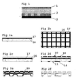
- An electrochemical cell with the working electrode, the sample, as anode and the counter electrode as cathode are formed, as shown in figure 1 .
- An external potential is applied to drive the oxidation process at the working electrode.
- the corresponding reduction at the cathode is usually hydrogen gas formation.
- electrolyte, and etchant neutral salt solutions or very diluted mixtures of conventional etchant can be used. The applied potential and the electric field from it give a directional etching in the vertical direction.
- Another problem in electrochemical etching is non-uniformed current density distribution arising from accumulated currents from non-etched areas, due to the fact that all parts of the counter electrode is in contact with the electrolyte, not only the desired areas above the etched parts.
- the second option, additive techniques, for pattern transfer is to add material in the structure formed on top of the substrate by the pattern-defining step. Electro-deposition, physical vapour deposition and chemical vapour deposition are examples of additive processes.
- the etching material which is not to be etched away is usually coated with an etching preventing layer, a so called mask or resist.
- an etching preventing layer a so called mask or resist.
- the primary technique to define patterns to be etched is photolithography and a common etching preventing layer is a photo-resist.
- the photo-resist is exposed by electromagnetic radiation and developed to transfer the pattern where etching is wanted. Every sample that is etched has to be coated with resist, pre-baked, exposed, developed and hard-baked before the etching process can start.
- Fig 6 shows a conventional etching process with the lithography process.
- the complicated nature of the pattern defining lithography process and the large number of lithography steps needed to fabricate a micro-device makes it to a major time and cost carrier in the total manufacturing chain.
- EP 1060299 From the European patent publication EP 1060299 it is known to use a method of making, by etching, depressions in selected portions of an etching surface by using an electrode with electrically conductive electrode portions in selected portions of an electrode surface, where the electrode portions is forming an electrode pattern which corresponds to the etching pattern.
- the method is different compared to the present invention by using electromagnetic radiation to dissolve a passivating layer, which is formed on the etching material. During etching the electrode is placed at a distance from the electrically conductive etching material, which also differs from the present invention.
- the electrodes according to EP 1060299 has to be transparent to electromagnetic radiation and they do not compensate for unevenness in the micro/nano areas.
- WO 9845504 discloses a method for electroplating using an electroplating article, an anode and a substrate.
- the electroplating article is put in contact with the substrate.
- the external anode is placed separated from the substrate and the electroplating article, all immersed in an electrolyte.
- a potential is applied over the external anode and the substrate, resulting in material transferred from the anode, through the porous carrier of the electroplating article and plated on the substrate in a pattern defined by the insulating mask of the electroplating article.
- the electrolyte volume between the electroplating article and the anode can be agitated to improve mass transfer of electroactive ions.
- an electroplating article that consists of a patterned mask placed onto an anode.
- the anode can be soluble or insoluble and can include an erodable layer.
- the material is transferred from the anode material in the electroplating article, thus the electroplating acticle is eroded during use, but can be periodically redressed and reused.
- One object of the present invention is to simplify production of applications involving micro and nano structures where an etching or plating pattern, which is defined by a conductive electrode, a master electrode, is replicated on an electrically conductive material, a substrate.
- electrochemical pattern replication method This object is met by a special contact electrochemical plating method that is called the electrochemical pattern replication method.
- the electrochemical pattern replication method it is stated as the ECPR method further in this description.
- This method is based on a structured electrode and an electrochemical plating method.
- the master electrode and the substrate are put in close contact, where local plating cells are formed in the open or closed cavities between the master electrode and the substrate.
- Another object is to design the master electrode, which is used in the ECPR method.
- This object is met by integrating a counter electrode and pattern defining structures of an electrochemical plating cell into one device, the master electrode.
- This master electrode will operate both as counter electrode and pattern master in the plating cell used in the ECPR method.
- the substrate, the sample on which the pattern is to be plated on, operates as a working electrode in the plating cell used in the ECPR method.
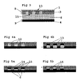
- a master electrode 8 of the present invention operates both as a counter electrode 1 and a pattern defining master and a substrate 9 operates as a working electrode 2 in an etching/plating cell, which is shown in fig.3 , used in the ECPR process, according to the present invention.
- the purpose of the master electrode 8 is to provide electrical connection to all local etching cells 12 formed when compressing the master electrode 8 and the substrate 9 and, at the same time, to provide electrical insulation to the areas where electrochemical action is undesired, i.e. at the contact areas between an insulating pattern layer 3 and the substrate 9. To enable a well-defined pattern transfer, even for relatively rough substrate surfaces, a conformable behaviour is needed. This is satisfied by a compressible elastomer layer 20, 21 within the master electrode construction.
- the insulating pattern layer 3 is fabricated by using an electrically insulating material that is chemically inert in the electrolytes that is used, enables high aspect ratio structures and is easily patterned using i.e. UV, X-ray, electron beam, laser or etching/plating combined with an insulating process.
- electrically insulating material that is chemically inert in the electrolytes that is used, enables high aspect ratio structures and is easily patterned using i.e. UV, X-ray, electron beam, laser or etching/plating combined with an insulating process.
- Examples of insulating materials to be used are polyimide, SU-8, SC 100, MRL 6000, ED-resist and Teflon materials.
- the insulating portions are made by anodising a conducting material, e.g. a metal.
- the counter electrode 1 is a conducting electrode layer 1'.
- the conducting electrode layer could be a flexible conducting foil 1'', a solid metal sheet or a thin conducting layer on a mechanical support layer 23.
- the conducting electrode layers 1', 1'' are deposited on a mechanical support layer 23 or an elastomer layer 21 with a very high surface uniformity, the two features planarity and high surface uniformity are combined.
- Crucial material characteristics for the conducting electrode layer 1', 1'' are high conductivity, chemically inertness in the electrolytes used, good seed layers for electrochemical material deposition and suitable methods for depositing or in other ways incorporating the layer into the integrated master electrode construction. Examples of conducting electrode layer 1', 1'' materials used are stainless steel, platinum, palladium, titanium, gold, graphite, chromium, aluminium and nickel.
- the master electrode is manufactured by using a conventional microfabrication method, which is described in figure 6 .
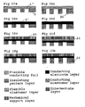
- the different embodiments of master electrodes used for ECPR processing are described in figures 10a-10h . All different electrode layer 1', 1'' embodiments can be combined with all different combinations of insulating pattern layer 3, flexible elastomer layer 20, 21, mechanical support layer23 and intermediate metal layers 22. All these configurations can be used for both an open cavity concept and a closed cavity concept. These concepts will be explained further on in the document.
- Master electrodes for the open cavity configuration may be fabricated using the method described below.
- the master electrode used for open cavity configuration is fabricated in two major steps.
- the counter electrode layer 1 is shaped and prepared to meet the different requirements stipulated as crucial for successful ECPR processing.
- an insulating pattern layer 3 is deposited and patterned on the counter electrode layer 1.
- titanium has been chosen as a master electrode material since it is inert in the electrolytes being used. Furthermore, anodising can form a dense insulating outer layer of TiO 2 at the contact areas. It is possible to use other materials as well, which has been mentioned before.
- the master electrode 8 Since the master electrode 8 is in contact with the working electrode 2, some parts of the master electrode have to be made of an insulating material, an insulating pattern layer 3 on the contact side, the master side 11.
- the insulating pattern layer 3 prevents the areas where etching is undesired from etchant contact.
- All the manufacturing steps of the master electrode 8 is carried out with conventional microfabrication processes, known from prior art and shown in figure 6 .
- the master electrode 8 will be fabricated out of two titanium foil layers 16, as stated before, which is shown in figures 2a to 2e , with a sacrificial photo-resist layer 17 in between, to form gas/electrolyte transport channels.
- An example of how the fabrication of this master electrode could be performed is as follows:
- All fabrication steps for the outer side 10 of the master electrode 8 are standardised and do not depend on what kind of master structure that is used. Universal standard masks can be used. Only the masks for the master-side 11 have to be selected for every specific master structure. The master electrode is ready to be mounted in an etching cell.
- a closed cavity master electrode may be performed in the same way as the above described fabrication process of the open cavity master electrode except for the sacrificial resist layer.
- Several combinations of material are shown in fig 10a to 10h .
- a very important part of the ECPR process is to use a suitable insulating layer.
- One of many benefits of the process is that it would no longer be needed to apply a resist on each sample but instead the resist would be out on a reusable master. For this to be a benefit it of course requires that the resist withstand several process cycles. Besides that, the resist also governs how small structures that can be made, what volume electrolyte to sample depth ratio one can have and also, how easy it would be to keep all structures in contact with the sample.
- Electrodeposited photo-resist, ED resist which is often used for lithography processes, is suitable for these etching processes and it can be deposited with very precise thickness control.
- the embodiments of the master electrode according to the present invention are in no way limited to the example constructions showed neither in figure 2a-2i , 10a-10h nor to the materials listed as suitable in the description above.
- An electrical conductive material durable to electrochemical stresses e.g. copper, may be used as substrate material.
- the electrolyte composition is crucial in controlling an electrochemical process and its different features. Conductivity, ion mobility, ionic atmosphere, relaxation, migration, diffusion and transport numbers are important concepts.
- Reducing components e.g. metal ions
- Reducing components could be added to the electrolyte solution if one wants to prevent deposition of substrate material and to cause the etch process to stop in a natural way.
- reducing components When reducing components are added the reduction process will take place in the electrolyte and there will be a natural ending of the etching process when there is a balance between the reduction components and the deposited components.
- the substrate 9 and the master electrode 8 are put together in close contact and form an etching cell, as shown in fig. 4a .
- the insulating pattern layer 3 defines the distance between the counter electrode 1 part of the master electrode and the substrate 9. Thanks to the fact that the distance is short and precise all over the surface it solves the problems with non-uniform current density distribution and non-etched areas. It also minimises the resistive losses from charge transfer in the electrolyte.
- the structure will be replicated on the substrate 9 because the field and motion of the ions in the etching/plating solution is controlled in vertical direction by the master electrode 8.
- etching cells 12 Since the master electrode 8 and the substrate 9 are in close contact, closed or open cavities, local etching cells 12, is provided between the electrode surfaces. If the cavities are open or closed depends on how master electrode 8, that is used, is constructed, with or without sacrificial resist layer 17. The cavities are considered to be closed further in the document. These, very small and well-controlled, spaces between the electrodes admits an effective etching with high precision. Every local etching cell 12 has a surface on the master electrode 8, which corresponds to a surface on the substrate 9 which should be etched away and thereby avoiding the problems with fluctuating current density distribution in the vicinity of large insulating areas with adjacent small structures.
- an ECPR method for etching selected parts of a surface defined by the master electrode which was described above, has thus been provided.
- FIGS 3, 4a and 4b show the different steps in the ECPR etching process, according to relevant technology. The steps are as follows:
- FIG. 5a and 5b shows the different steps in the ECPR plating process, according to the present invention.
- the plating process is almost the same as the etching process except following steps:
- An optimised mass-transport of electro-active ions in these cells has to occur to achieve an optimised ECPR-process.
- the mass-transfer with movement of material from one location in solution to another, arises from differences in electrical or chemical potential at two locations, or from movement of a volume element of solution.
- the high A/V ratio implies large frictional forces per unit volume, making all electrolyte volumes to stagnant layers. This means no forced convective mass transfer, except when using ultrasound, leaving only the diffusion and migration mechanisms to exert the material transport.
- the parameters that were adjusted in the solution were the pH-value and the electro-active species/supporting electrolyte ratio.
- a concentration of electro-active species of 10 to 1200 mM is preferred.
- Electro-deposition is the reversed electrochemical etching process, where ions from the electrolyte is reduced and deposited on the cathode.
- the same conditions apply and the same parameters control the two processes.
- the geometry of the electrochemical cell and the use of additives are a solution to enable "bottom-up-filling" without any voids. Additives are added to give a sufficient electro-deposition.
- Additives is something that is often used in plating processes to make the plating even. It contains several active components but predominantly it prevents the forming of pillars by being attracted to and covered high current density areas as soon as the pillars start forming. This turned out to be the key to the problem and as soon as it was used a clean and solid substrate material was formed on the cathode.
- Coveted additives are wetting agents, which lowers the surface tension, accelerators, which are molecules that locally increases current density where they absorb, suppressors, which are polymers which tend to form current-suppressing film on the entire substrate surface (could sometimes use chloride as co-suppressor) and levelers, which are current suppressing molecules with mass transfer dependent distribution.
- the counter-ions are exchanged to ones, which provide a higher solubility product.
- a sequestering agent could be added, e.g. EDTA, to dissolve more metal ions without causing any further precipitation.
- Pulsed-voltage was chosen because it enhances mass transfer and disturbs the formation of blocking layers at the electrode-solution interface. Tests were made to determine what kind of frequencies, duty cycles and potentials to use. Both periodic pulse reverse voltage (PPR) and complex waveforms have been used with success. Frequencies of 2 to 20 kHz have been tested with satisfactory results but also higher frequencies are possible. In the described embodiment the frequency of 5 kHz is preferred. The potential is from 0 to 10 V.
- Ultrasound is sometimes used together with pulsed voltage to enhance the mass-transport by micro-convection.
- a machine solution to exert the actions described in this document is a crucial part of the invention.
- the purpose of the machine is to compress the two electrode surfaces, the master electrode and the substrate, to create the micro/nano cavities where the local electrochemical cells are formed.
- flexible layers in the machine for macro scale conformable behaviour and plane parallelism, are combined with flexible layers within the master electrode, which enables micro- and nano scale conformable behaviour. In this way both bent and dented substrates with a rather high surface roughness can be used for ECPR processing.
- both master electrode 8 and substrate 9 has to be electrically contacted in the same machine solution. This has been done with outer side 10 contacting on the master electrode 8 and front side, the contacting side, contacting on the substrate 9.
- the invention is in no way depending on this configuration.
- the first embodiment which is shown in figure 8 , is based on a membrane solution where a pressurised membrane 24 is expanded against the master electrode 8 or the substrate 9.
- the medium 19 inside the pressure volume can be both gas and liquid. Gas bubbles are eliminated by a combination of ultrasound and vacuum, or just using ultrasound.
- electrical contact to the master electrode 8 is provided from the outer side 10, i.e. from the membrane 24 and contact to the substrate 9 from the front side. Plane parallelism is ensured by the nature of the expanding membrane, applying an even pressure in a conformable way. Both flexible and rigid master electrodes and substrates can be used in this embodiment.
- the second embodiment is based on a cylinder, which is shown in figure 9 , containing a moveable piston, not shown in the figure.
- the entire system is confined. Pressure is applied to compress the two electrodes 8,9 pneumatically using a combination of vacuum and overpressure or hydraulically using a hydraulic piston or mechanically using a screw. Gas bubbles are eliminated by a combination of ultrasound and vacuum.
- electrical contact 26 to the master electrode is provided from the outer side 10 and contact to the substrate 25 from the front side using conducting movable rods. Plane parallelism is ensured by two flexible elastomer layers between the sample and the piston, one being more compressible than the other is. These elastomer layers can also be placed behind the master electrode 8, i.e. between master electrode and cylinder wall. Both flexible and rigid master electrodes and substrates can be used in this embodiment.
Landscapes
- Engineering & Computer Science (AREA)
- Chemical & Material Sciences (AREA)
- Chemical Kinetics & Catalysis (AREA)
- Electrochemistry (AREA)
- Materials Engineering (AREA)
- Metallurgy (AREA)
- Organic Chemistry (AREA)
- Microelectronics & Electronic Packaging (AREA)
- Manufacturing & Machinery (AREA)
- Electroplating Methods And Accessories (AREA)
- Micromachines (AREA)
- Exposure And Positioning Against Photoresist Photosensitive Materials (AREA)
- Weting (AREA)
- ing And Chemical Polishing (AREA)
- Printing Methods (AREA)
- Cell Electrode Carriers And Collectors (AREA)
- Electrical Discharge Machining, Electrochemical Machining, And Combined Machining (AREA)
Priority Applications (1)
| Application Number | Priority Date | Filing Date | Title |
|---|---|---|---|
| EP10182946.3A EP2322694B1 (en) | 2001-06-15 | 2002-06-17 | Method for defining and replicating structures in conducting materials |
Applications Claiming Priority (3)
| Application Number | Priority Date | Filing Date | Title |
|---|---|---|---|
| SE0102144A SE523309E (sv) | 2001-06-15 | 2001-06-15 | Metod, elektrod och apparat för att skapa mikro- och nanostrukturer i ledande material genom mönstring med masterelektrod och elektrolyt |
| SE0102144 | 2001-06-15 | ||
| PCT/SE2002/001179 WO2002103085A1 (en) | 2001-06-15 | 2002-06-17 | Method and electrode for defining and replicating structures in conducting materials |
Related Child Applications (2)
| Application Number | Title | Priority Date | Filing Date |
|---|---|---|---|
| EP10182946.3A Division EP2322694B1 (en) | 2001-06-15 | 2002-06-17 | Method for defining and replicating structures in conducting materials |
| EP10182946.3 Division-Into | 2010-09-30 |
Publications (2)
| Publication Number | Publication Date |
|---|---|
| EP1404899A1 EP1404899A1 (en) | 2004-04-07 |
| EP1404899B1 true EP1404899B1 (en) | 2012-10-31 |
Family
ID=20284507
Family Applications (2)
| Application Number | Title | Priority Date | Filing Date |
|---|---|---|---|
| EP02739042A Expired - Lifetime EP1404899B1 (en) | 2001-06-15 | 2002-06-17 | Method and electrode for defining and replicating structures in conducting materials |
| EP10182946.3A Expired - Lifetime EP2322694B1 (en) | 2001-06-15 | 2002-06-17 | Method for defining and replicating structures in conducting materials |
Family Applications After (1)
| Application Number | Title | Priority Date | Filing Date |
|---|---|---|---|
| EP10182946.3A Expired - Lifetime EP2322694B1 (en) | 2001-06-15 | 2002-06-17 | Method for defining and replicating structures in conducting materials |
Country Status (12)
| Country | Link |
|---|---|
| US (4) | US7790009B2 (enExample) |
| EP (2) | EP1404899B1 (enExample) |
| JP (2) | JP4546078B2 (enExample) |
| KR (1) | KR101250685B1 (enExample) |
| CN (1) | CN1294296C (enExample) |
| CA (1) | CA2462098C (enExample) |
| DK (1) | DK1404899T3 (enExample) |
| ES (2) | ES2397919T3 (enExample) |
| PT (1) | PT1404899E (enExample) |
| RU (1) | RU2296820C2 (enExample) |
| SE (1) | SE523309E (enExample) |
| WO (1) | WO2002103085A1 (enExample) |
Families Citing this family (72)
| Publication number | Priority date | Publication date | Assignee | Title |
|---|---|---|---|---|
| WO2001017320A1 (en) | 1999-08-27 | 2001-03-08 | Lex Kosowsky | Current carrying structure using voltage switchable dielectric material |
| US7825491B2 (en) | 2005-11-22 | 2010-11-02 | Shocking Technologies, Inc. | Light-emitting device using voltage switchable dielectric material |
| WO2003080502A1 (en) * | 2002-03-25 | 2003-10-02 | Matvice Ehf. | A method and apparatus for processing nanoscopic structures |
| US8294025B2 (en) | 2002-06-08 | 2012-10-23 | Solarity, Llc | Lateral collection photovoltaics |
| JP4892684B2 (ja) * | 2004-01-12 | 2012-03-07 | ザ・リージェンツ・オブ・ザ・ユニバーシティ・オブ・カリフォルニア | ナノスケール電気リソグラフィー法 |
| GB0416600D0 (en) * | 2004-07-24 | 2004-08-25 | Univ Newcastle | A process for manufacturing micro- and nano-devices |
| GB0416952D0 (en) * | 2004-07-30 | 2004-09-01 | Renishaw Plc | Scale making method |
| BRPI0515058A (pt) * | 2004-09-08 | 2008-07-01 | Nil Technology Aps | selo por nanoimpressão e método para imprimir um padrão litográfico em um substrato receptor |
| FR2885913B1 (fr) * | 2005-05-18 | 2007-08-10 | Centre Nat Rech Scient | Element composite comprenant un substrat conducteur et un revetement metallique nanostructure. |
| KR101147087B1 (ko) * | 2005-06-28 | 2012-05-17 | 엘지디스플레이 주식회사 | 평판표시소자의 제조방법 |
| WO2007058604A1 (en) * | 2005-11-18 | 2007-05-24 | Replisaurus Technologies Ab | Master electrode and method of forming the master electrode |
| KR20080084812A (ko) | 2005-11-22 | 2008-09-19 | 쇼킹 테크놀로지스 인코포레이티드 | 과전압 보호를 위해 전압 변환가능 재료를 포함하는 반도체디바이스 |
| FR2898138B1 (fr) * | 2006-03-03 | 2008-05-16 | Commissariat Energie Atomique | Procede de structuration electrochimique d'un materiau conducteur ou semi-conducteur, et dispositif de mise en oeuvre. |
| EP1835339B1 (fr) * | 2006-03-15 | 2012-05-16 | Rolex S.A. | Procédé de fabrication par technologie de type liga d'une structure métallique monocouche ou multicouche, et structure obtenue |
| DE102006013362A1 (de) * | 2006-03-16 | 2007-09-27 | Siemens Ag | Verfahren zum Herstellen einer elektrischen Komponente mit einer Nanonadelstruktur |
| US20080029405A1 (en) * | 2006-07-29 | 2008-02-07 | Lex Kosowsky | Voltage switchable dielectric material having conductive or semi-conductive organic material |
| US7968014B2 (en) | 2006-07-29 | 2011-06-28 | Shocking Technologies, Inc. | Device applications for voltage switchable dielectric material having high aspect ratio particles |
| JP2010521058A (ja) | 2006-09-24 | 2010-06-17 | ショッキング テクノロジーズ,インコーポレイテッド | ステップ電圧応答を有する電圧切り換え可能な誘電体材料の組成及び該誘電体材料の製造方法 |
| JP4694519B2 (ja) * | 2007-02-28 | 2011-06-08 | 富士通株式会社 | マイクロ構造体およびマイクロ構造体製造方法 |
| CN100545648C (zh) * | 2007-05-15 | 2009-09-30 | 中国科学院长春应用化学研究所 | 一种微盘电极或微盘阵列电极的制备方法 |
| US7793236B2 (en) | 2007-06-13 | 2010-09-07 | Shocking Technologies, Inc. | System and method for including protective voltage switchable dielectric material in the design or simulation of substrate devices |
| US9157141B2 (en) * | 2007-08-24 | 2015-10-13 | Schlumberger Technology Corporation | Conditioning ferrous alloys into cracking susceptible and fragmentable elements for use in a well |
| CH704572B1 (fr) * | 2007-12-31 | 2012-09-14 | Nivarox Sa | Procédé de fabrication d'une microstructure métallique et microstructure obtenue selon ce procédé. |
| US8206614B2 (en) | 2008-01-18 | 2012-06-26 | Shocking Technologies, Inc. | Voltage switchable dielectric material having bonded particle constituents |
| US8203421B2 (en) | 2008-04-14 | 2012-06-19 | Shocking Technologies, Inc. | Substrate device or package using embedded layer of voltage switchable dielectric material in a vertical switching configuration |
| KR100894710B1 (ko) * | 2008-06-27 | 2009-04-24 | (주) 월드비젼 | 윈도우 일체형 터치스크린 및 이의 제조방법 |
| EP2166125A1 (en) * | 2008-09-19 | 2010-03-24 | ALSTOM Technology Ltd | Method for the restoration of a metallic coating |
| US9208931B2 (en) | 2008-09-30 | 2015-12-08 | Littelfuse, Inc. | Voltage switchable dielectric material containing conductor-on-conductor core shelled particles |
| WO2010039902A2 (en) | 2008-09-30 | 2010-04-08 | Shocking Technologies, Inc. | Voltage switchable dielectric material containing conductive core shelled particles |
| US8362871B2 (en) | 2008-11-05 | 2013-01-29 | Shocking Technologies, Inc. | Geometric and electric field considerations for including transient protective material in substrate devices |
| WO2010054677A1 (en) * | 2008-11-14 | 2010-05-20 | Replisaurus Technologies Inc. | A system for plating a conductive substrate, and a substrate holder for holding a conductive substrate during plating thereof |
| US8399773B2 (en) | 2009-01-27 | 2013-03-19 | Shocking Technologies, Inc. | Substrates having voltage switchable dielectric materials |
| US9226391B2 (en) | 2009-01-27 | 2015-12-29 | Littelfuse, Inc. | Substrates having voltage switchable dielectric materials |
| US8272123B2 (en) | 2009-01-27 | 2012-09-25 | Shocking Technologies, Inc. | Substrates having voltage switchable dielectric materials |
| CN102550132A (zh) | 2009-03-26 | 2012-07-04 | 肖克科技有限公司 | 具有电压可切换电介质材料的元件 |
| EP2263972A1 (fr) * | 2009-06-12 | 2010-12-22 | Nivarox-FAR S.A. | Procédé de fabrication d'une microstructure métallique et microstructure obtenue selon ce procédé |
| US9053844B2 (en) | 2009-09-09 | 2015-06-09 | Littelfuse, Inc. | Geometric configuration or alignment of protective material in a gap structure for electrical devices |
| JP4768848B2 (ja) * | 2009-12-07 | 2011-09-07 | 株式会社東芝 | 電鋳用原盤及びその製造方法 |
| USD642277S1 (en) | 2009-12-23 | 2011-07-26 | Christopher John Farrell | Oral appliance |
| US9224728B2 (en) | 2010-02-26 | 2015-12-29 | Littelfuse, Inc. | Embedded protection against spurious electrical events |
| US9320135B2 (en) | 2010-02-26 | 2016-04-19 | Littelfuse, Inc. | Electric discharge protection for surface mounted and embedded components |
| US9082622B2 (en) | 2010-02-26 | 2015-07-14 | Littelfuse, Inc. | Circuit elements comprising ferroic materials |
| EP2593592B1 (en) | 2010-07-15 | 2018-05-16 | Luxembourg Institute of Science and Technology (LIST) | Separation of master electrode and substrate in ecpr |
| ES2592708T3 (es) | 2010-07-15 | 2016-12-01 | Luxembourg Institute Of Science And Technology (List) | Una hoja de contactos para la disposición entre una pinza de sujeción y un electrodo maestro en un proceso ECPR |
| EP2593585B1 (en) | 2010-07-15 | 2017-08-30 | Luxembourg Institute of Science and Technology (LIST) | Leveling of master electrode and substrate in ecpr, and a chuck therefor |
| WO2012007524A1 (en) | 2010-07-15 | 2012-01-19 | Replisaurus Group Sas | Filling of a printing chamber and a chuck therefore |
| WO2012007526A2 (en) | 2010-07-15 | 2012-01-19 | Replisaurus Group Sas | Device, system and method for use in machines for electrochemical pattern replication |
| EP2593590B1 (en) | 2010-07-15 | 2017-10-04 | Luxembourg Institute of Science and Technology (LIST) | System for automated handling of masters and substrate |
| ES2590130T3 (es) | 2010-07-15 | 2016-11-18 | Luxembourg Institute Of Science And Technology (List) | Método para lavar y/o secar una cámara de replicación electroquímica de modelos (ECPR), y mandriles y conjuntos de mandril correspondientes |
| WO2012007520A1 (en) | 2010-07-15 | 2012-01-19 | Replisaurus Group Sas | A chuck, and a method for bringing a first and a second substrate together |
| RU2463121C2 (ru) * | 2010-08-31 | 2012-10-10 | Государственное образовательное учреждение высшего профессионального образования "Казанский государственный энергетический университет" (КГЭУ) | Способ изготовления электрически изолированной металлической ленты и линия для его осуществления |
| AT510593B1 (de) * | 2010-12-15 | 2012-05-15 | Markus Dipl Ing Dr Hacksteiner | Vorrichtung zum metallisieren von wafern |
| DK2655698T3 (da) | 2010-12-23 | 2019-08-12 | Luxembourg Institute Of Science And Tech | Hovedelektrode til ecpr samt fremgangsmåder til fremstilling af denne |
| WO2012084046A1 (en) | 2010-12-23 | 2012-06-28 | Replisaurus Group Sas | An ecpr master electrode, and a method for providing such master electrode |
| EP2655701B1 (en) | 2010-12-23 | 2018-08-29 | Luxembourg Institute of Science and Technology (LIST) | A method for providing an ecpr master electrode and an ecpr master electrode |
| EP2655700A1 (en) | 2010-12-23 | 2013-10-30 | Centre de Recherche Public - Gabriel Lippmann | An ecpr master electrode and a method for providing such ecpr master electrode |
| RU2497747C2 (ru) * | 2011-04-05 | 2013-11-10 | Федеральное государственное бюджетное образовательное учреждение высшего профессионального образования "Московский педагогический государственный университет" (МПГУ) | Способ получения металлических реплик конической формы на основе полимерных шаблонов |
| EP2696934B1 (en) * | 2011-04-15 | 2017-08-09 | CorTec GmbH | Neural electrode and method for fabricating the same |
| ES2624739T3 (es) | 2011-06-07 | 2017-07-17 | Luxembourg Institute Of Science And Technology (List) | Electrodo maestro ECPR y un procedimiento para proporcionar dicho electrodo maestro |
| EP2533271B1 (en) | 2011-06-07 | 2014-05-21 | Centre de Recherche Public - Gabriel Lippmann | An ecpr master electrode, and a method for providing such master electrode |
| EP2533272B1 (en) | 2011-06-07 | 2014-03-12 | Centre de Recherche Public - Gabriel Lippmann | An ecpr master electrode, and a method for providing such master electrode |
| AU349029S (en) | 2012-08-31 | 2013-06-06 | Orthodontic appliance | |
| RU2529592C2 (ru) * | 2012-11-19 | 2014-09-27 | Общество с Ограниченной Ответственностью "Фабрика новых материалов" | Способ электрохимической рентгеновской бесконтактной литографии |
| JP6107799B2 (ja) * | 2014-12-03 | 2017-04-05 | トヨタ自動車株式会社 | 表面処理方法および表面処理装置 |
| USD767146S1 (en) | 2015-02-09 | 2016-09-20 | Christopher John Farrell | Orthodontic appliance |
| CA168308S (en) | 2015-11-09 | 2017-03-22 | Myosa Pty Ltd | Oral appliance |
| US10465307B2 (en) | 2015-11-19 | 2019-11-05 | Fabric8Labs, Inc. | Apparatus for electrochemical additive manufacturing |
| AU201710942S (en) | 2017-02-16 | 2017-10-06 | Orthodontic appliance | |
| FR3072690B1 (fr) * | 2017-10-24 | 2021-07-30 | Centre Techn Ind Mecanique | Procede de traitement de surface d'une piece mecanique realisee dans un materiau conducteur |
| LU100919B1 (en) | 2018-08-27 | 2020-02-27 | Luxembourg Inst Science & Tech List | Metal-CNT composite, production method and materials therefor |
| KR102210785B1 (ko) * | 2019-02-07 | 2021-02-02 | 경북대학교 산학합력단 | 더블 패터닝을 이용한 나노 메쉬 기반의 일체형 금속 전도체 제조방법 및 이에 의해 제조된 일체형 금속 전도체 |
| US12139810B2 (en) * | 2020-06-15 | 2024-11-12 | Arizona Board Of Regents On Behalf Of Arizona State University | Localized electrochemical deposition |
Family Cites Families (35)
| Publication number | Priority date | Publication date | Assignee | Title |
|---|---|---|---|---|
| US2306082A (en) * | 1940-04-27 | 1942-12-22 | Clarence O Prest | Method for line or design reproduction by electrolysis |
| US3190822A (en) * | 1961-01-09 | 1965-06-22 | Burnham John | Process for electrolytically etching valve metal surfaces |
| US3240685A (en) * | 1962-02-23 | 1966-03-15 | Ibm | Method and device for selective anodization |
| GB1098182A (en) | 1963-12-27 | 1968-01-10 | Ibm | Electrolyte or electroless plating process |
| CA791112A (en) * | 1964-06-30 | 1968-07-30 | J. Kahan George | Catalytically active palladium coatings |
| US3582477A (en) * | 1969-02-20 | 1971-06-01 | Paul Gelb | Selective electroplating method |
| JPS5456619U (enExample) * | 1977-09-28 | 1979-04-19 | ||
| JPS5456619A (en) | 1977-10-13 | 1979-05-07 | Tokyo Yogyo Kk | Spray repairing material for blast furnace tapping spout |
| GB1600667A (en) | 1978-05-26 | 1981-10-21 | Pryor Edward & Son | Electrolytic marking of metal articles |
| US4279709A (en) * | 1979-05-08 | 1981-07-21 | The Dow Chemical Company | Preparation of porous electrodes |
| US4734174A (en) * | 1986-12-17 | 1988-03-29 | Polaroid Corporation | Electrochemical formation of thin-film electrodes |
| JPH01234590A (ja) * | 1988-03-16 | 1989-09-19 | Toshiba Eng Co Ltd | 部分メッキ装置 |
| US4932518A (en) * | 1988-08-23 | 1990-06-12 | Shipley Company Inc. | Method and apparatus for determining throwing power of an electroplating solution |
| US5294504A (en) * | 1988-08-30 | 1994-03-15 | Osaka Gas Company, Ltd. | Three-dimensional microstructure as a substrate for a battery electrode |
| JPH04236800A (ja) * | 1991-01-16 | 1992-08-25 | Fujitsu Ltd | 電解エッチング方法 |
| US5196109A (en) * | 1991-08-01 | 1993-03-23 | Geoffrey Scott | Trivalent chromium electrolytes and plating processes employing same |
| JPH0593300A (ja) * | 1991-09-30 | 1993-04-16 | Riyouichi Aogaki | 電解エツチング方法 |
| US5252196A (en) * | 1991-12-05 | 1993-10-12 | Shipley Company Inc. | Copper electroplating solutions and processes |
| JPH06299390A (ja) * | 1993-04-13 | 1994-10-25 | Seiko Instr Inc | 微細加工方法及び装置 |
| DE4344387C2 (de) * | 1993-12-24 | 1996-09-05 | Atotech Deutschland Gmbh | Verfahren zur elektrolytischen Abscheidung von Kupfer und Anordnung zur Durchführung des Verfahrens |
| WO1995034084A1 (en) * | 1994-06-09 | 1995-12-14 | Raychem Corporation | Electrical devices |
| DK172937B1 (da) * | 1995-06-21 | 1999-10-11 | Peter Torben Tang | Galvanisk fremgangsmåde til dannelse af belægninger af nikkel, kobalt, nikkellegeringer eller kobaltlegeringer |
| KR0147996B1 (ko) * | 1995-06-30 | 1998-10-15 | 배순훈 | 박막 헤드의 패턴 평탄화 방법 |
| CN1235271C (zh) * | 1995-10-17 | 2006-01-04 | 佳能株式会社 | 生产半导体器件的工艺 |
| JPH103233A (ja) * | 1996-04-15 | 1998-01-06 | Fuji Xerox Co Ltd | 画像形成方法、画像形成媒体、被転写媒体及び画像形成装置 |
| WO1998000877A1 (en) | 1996-07-02 | 1998-01-08 | Wilson Greatbatch Ltd. | Preparation and use of thin flexible cathodes in alkali metal electrochemical cells |
| WO1998045504A1 (en) * | 1997-04-04 | 1998-10-15 | University Of Southern California | Article, method, and apparatus for electrochemical fabrication |
| FR2773652B1 (fr) * | 1998-01-14 | 2002-10-11 | Sgs Thomson Microelectronics | Circuit de generation d'un signal d'activation commande |
| JP4498601B2 (ja) | 1998-03-05 | 2010-07-07 | オブデュキャット、アクチボラグ | エッチング方法 |
| US5947027A (en) * | 1998-09-08 | 1999-09-07 | Motorola, Inc. | Printing apparatus with inflatable means for advancing a substrate towards the stamping surface |
| DE19935558B4 (de) * | 1999-07-30 | 2010-11-25 | Nawotec Gmbh | Verfahren zur Erzeugung von Strukturen in einem Substrat im Nanometerbereich |
| JP3441058B2 (ja) * | 1999-12-03 | 2003-08-25 | 理化学研究所 | キャピラリーゲル電気泳動用マイクロチップおよびその製造方法 |
| SE515607C2 (sv) | 1999-12-10 | 2001-09-10 | Obducat Ab | Anordning och metod vid tillverkning av strukturer |
| KR100500684B1 (ko) * | 1999-12-29 | 2005-07-12 | 비오이 하이디스 테크놀로지 주식회사 | 4-마스크 공정을 이용한 액정 디스플레이의 제조 방법 |
| KR20010105994A (ko) * | 2000-05-20 | 2001-11-29 | 구자홍 | 디스크 드라이버의 트레이 |
-
2001
- 2001-06-15 SE SE0102144A patent/SE523309E/xx not_active IP Right Cessation
-
2002
- 2002-06-17 CN CNB028119266A patent/CN1294296C/zh not_active Expired - Fee Related
- 2002-06-17 ES ES02739042T patent/ES2397919T3/es not_active Expired - Lifetime
- 2002-06-17 EP EP02739042A patent/EP1404899B1/en not_active Expired - Lifetime
- 2002-06-17 EP EP10182946.3A patent/EP2322694B1/en not_active Expired - Lifetime
- 2002-06-17 ES ES10182946.3T patent/ES2645700T3/es not_active Expired - Lifetime
- 2002-06-17 PT PT2739042T patent/PT1404899E/pt unknown
- 2002-06-17 DK DK02739042.6T patent/DK1404899T3/da active
- 2002-06-17 WO PCT/SE2002/001179 patent/WO2002103085A1/en not_active Ceased
- 2002-06-17 CA CA2462098A patent/CA2462098C/en not_active Expired - Lifetime
- 2002-06-17 JP JP2003505393A patent/JP4546078B2/ja not_active Expired - Fee Related
- 2002-06-17 RU RU2003136088/02A patent/RU2296820C2/ru not_active IP Right Cessation
- 2002-06-17 KR KR1020037016336A patent/KR101250685B1/ko not_active Expired - Fee Related
-
2003
- 2003-12-15 US US10/734,223 patent/US7790009B2/en not_active Expired - Fee Related
-
2007
- 2007-03-09 US US11/716,166 patent/US20070151858A1/en not_active Abandoned
-
2009
- 2009-06-15 JP JP2009142804A patent/JP2009235578A/ja active Pending
-
2010
- 2010-05-27 US US12/801,219 patent/US20110000784A1/en not_active Abandoned
-
2012
- 2012-03-12 US US13/417,808 patent/US8741113B2/en not_active Expired - Fee Related
Also Published As
| Publication number | Publication date |
|---|---|
| ES2645700T3 (es) | 2017-12-07 |
| JP2009235578A (ja) | 2009-10-15 |
| WO2002103085A1 (en) | 2002-12-27 |
| RU2003136088A (ru) | 2005-05-10 |
| JP4546078B2 (ja) | 2010-09-15 |
| KR101250685B1 (ko) | 2013-04-03 |
| US7790009B2 (en) | 2010-09-07 |
| US20070151858A1 (en) | 2007-07-05 |
| CN1294296C (zh) | 2007-01-10 |
| RU2296820C2 (ru) | 2007-04-10 |
| HK1072083A1 (en) | 2005-08-12 |
| SE0102144D0 (sv) | 2001-06-15 |
| US20110000784A1 (en) | 2011-01-06 |
| US20040154828A1 (en) | 2004-08-12 |
| SE523309E (sv) | 2010-03-02 |
| ES2397919T3 (es) | 2013-03-12 |
| CA2462098A1 (en) | 2002-12-27 |
| DK1404899T3 (da) | 2013-02-04 |
| EP1404899A1 (en) | 2004-04-07 |
| PT1404899E (pt) | 2013-01-28 |
| US8741113B2 (en) | 2014-06-03 |
| KR20040028781A (ko) | 2004-04-03 |
| US20120228128A1 (en) | 2012-09-13 |
| SE0102144L (sv) | 2002-12-19 |
| JP2004530050A (ja) | 2004-09-30 |
| EP2322694A1 (en) | 2011-05-18 |
| EP2322694B1 (en) | 2017-08-02 |
| CN1555428A (zh) | 2004-12-15 |
| SE523309C2 (sv) | 2004-04-13 |
| CA2462098C (en) | 2014-01-14 |
Similar Documents
| Publication | Publication Date | Title |
|---|---|---|
| EP1404899B1 (en) | Method and electrode for defining and replicating structures in conducting materials | |
| JP2524458B2 (ja) | 電気化学マイクロマシニング方法 | |
| JP2004530050A5 (enExample) | ||
| US20090045066A1 (en) | Electrochemical Fabrication Methods with Enhanced Post Deposition Processing | |
| JP5214243B2 (ja) | マイクロ及びナノデバイスの製造工程 | |
| CN100406618C (zh) | 金属表面复杂三维微结构的加工方法及其装置 | |
| KR101274155B1 (ko) | 금속 마스크 제조방법 | |
| JP4815771B2 (ja) | 電気部品の製造方法 | |
| Llona et al. | Seedless electroplating on patterned silicon | |
| Datta | Electrochemical micromachining | |
| HK1072083B (en) | Method and electrode for defining and replicating structures in conducting materials | |
| Serrà et al. | Sono-electrodeposition transfer of micro-scale copper patterns on to A7 substrates using a mask-less method | |
| Datta | Microfabrication by through-mask electrochemical micromachining | |
| Datta | ELECTROCHEMICAL MICROMACHINING: AN ALTERNATE MICROFABRICATION TECHNOLOGY FOR MEMS | |
| Bhat et al. | Photo-defined electrically assisted etching method for metal stencil fabrication | |
| TW202242994A (zh) | 具高深寬比之孔洞之製備方法 | |
| JP2010077502A (ja) | 微細構造を有するアルミニウム及びその製造方法 |
Legal Events
| Date | Code | Title | Description |
|---|---|---|---|
| PUAI | Public reference made under article 153(3) epc to a published international application that has entered the european phase |
Free format text: ORIGINAL CODE: 0009012 |
|
| 17P | Request for examination filed |
Effective date: 20031212 |
|
| AK | Designated contracting states |
Kind code of ref document: A1 Designated state(s): AT BE CH CY DE DK ES FI FR GB GR IE IT LI LU MC NL PT SE TR |
|
| AX | Request for extension of the european patent |
Extension state: AL LT LV MK RO SI |
|
| RAP1 | Party data changed (applicant data changed or rights of an application transferred) |
Owner name: REPLISAURUS TECHNOLOGIES AB |
|
| 17Q | First examination report despatched |
Effective date: 20090520 |
|
| RAP1 | Party data changed (applicant data changed or rights of an application transferred) |
Owner name: REPLISAURUS GROUP SAS |
|
| RAP1 | Party data changed (applicant data changed or rights of an application transferred) |
Owner name: REPLISAURUS GROUP SAS |
|
| 111Z | Information provided on other rights and legal means of execution |
Free format text: AT BE CH CY DE DK ES FI FR GB GR IE IT LU MC NL PT SE TR Effective date: 20110104 |
|
| GRAC | Information related to communication of intention to grant a patent modified |
Free format text: ORIGINAL CODE: EPIDOSCIGR1 |
|
| GRAP | Despatch of communication of intention to grant a patent |
Free format text: ORIGINAL CODE: EPIDOSNIGR1 |
|
| RIN1 | Information on inventor provided before grant (corrected) |
Inventor name: MOELLER, PATRIK Inventor name: WIVEN-NILSSON, PETER Inventor name: FREDENBERG, MIKAEL |
|
| GRAS | Grant fee paid |
Free format text: ORIGINAL CODE: EPIDOSNIGR3 |
|
| GRAA | (expected) grant |
Free format text: ORIGINAL CODE: 0009210 |
|
| AK | Designated contracting states |
Kind code of ref document: B1 Designated state(s): AT BE CH CY DE DK ES FI FR GB GR IE IT LI LU MC NL PT SE TR |
|
| REG | Reference to a national code |
Ref country code: GB Ref legal event code: FG4D Ref country code: CH Ref legal event code: EP |
|
| REG | Reference to a national code |
Ref country code: AT Ref legal event code: REF Ref document number: 582080 Country of ref document: AT Kind code of ref document: T Effective date: 20121115 |
|
| REG | Reference to a national code |
Ref country code: IE Ref legal event code: FG4D |
|
| REG | Reference to a national code |
Ref country code: DE Ref legal event code: R096 Ref document number: 60243953 Country of ref document: DE Effective date: 20130103 |
|
| RAP2 | Party data changed (patent owner data changed or rights of a patent transferred) |
Owner name: CENTRE DE RECHERCHE PUBLIC - GABRIEL LIPPMANN |
|
| REG | Reference to a national code |
Ref country code: PT Ref legal event code: SC4A Free format text: AVAILABILITY OF NATIONAL TRANSLATION Effective date: 20130117 |
|
| REG | Reference to a national code |
Ref country code: CH Ref legal event code: NV Representative=s name: ZIMMERLI, WAGNER AND PARTNER AG, CH |
|
| REG | Reference to a national code |
Ref country code: DK Ref legal event code: T3 |
|
| REG | Reference to a national code |
Ref country code: SE Ref legal event code: TRGR |
|
| REG | Reference to a national code |
Ref country code: NL Ref legal event code: T3 Ref country code: NL Ref legal event code: SD Effective date: 20130201 |
|
| REG | Reference to a national code |
Ref country code: CH Ref legal event code: NV Representative=s name: ZIMMERLI, WAGNER AND PARTNER AG, CH |
|
| REG | Reference to a national code |
Ref country code: ES Ref legal event code: FG2A Ref document number: 2397919 Country of ref document: ES Kind code of ref document: T3 Effective date: 20130312 |
|
| REG | Reference to a national code |
Ref country code: PT Ref legal event code: PC4A Owner name: CENTRE DE RECHERCHE PUBLIC - GABRIEL LIPPMANN, LU Effective date: 20130307 |
|
| REG | Reference to a national code |
Ref country code: DE Ref legal event code: R081 Ref document number: 60243953 Country of ref document: DE Owner name: CENTRE DE RECHERCHE PUBLIC - GABRIEL LIPPMANN, LU Free format text: FORMER OWNER: REPLISAURUS HB, LUND, SE Effective date: 20121031 Ref country code: DE Ref legal event code: R081 Ref document number: 60243953 Country of ref document: DE Owner name: CENTRE DE RECHERCHE PUBLIC - GABRIEL LIPPMANN, LU Free format text: FORMER OWNER: REPLISAURUS GROUP SAS, CHAMPAGNE AU MONT D'OR, FR Effective date: 20130201 |
|
| REG | Reference to a national code |
Ref country code: GB Ref legal event code: 732E Free format text: REGISTERED BETWEEN 20130328 AND 20130403 |
|
| PG25 | Lapsed in a contracting state [announced via postgrant information from national office to epo] |
Ref country code: GR Free format text: LAPSE BECAUSE OF FAILURE TO SUBMIT A TRANSLATION OF THE DESCRIPTION OR TO PAY THE FEE WITHIN THE PRESCRIBED TIME-LIMIT Effective date: 20130201 Ref country code: CY Free format text: LAPSE BECAUSE OF FAILURE TO SUBMIT A TRANSLATION OF THE DESCRIPTION OR TO PAY THE FEE WITHIN THE PRESCRIBED TIME-LIMIT Effective date: 20121031 |
|
| PLBE | No opposition filed within time limit |
Free format text: ORIGINAL CODE: 0009261 |
|
| STAA | Information on the status of an ep patent application or granted ep patent |
Free format text: STATUS: NO OPPOSITION FILED WITHIN TIME LIMIT |
|
| 26N | No opposition filed |
Effective date: 20130801 |
|
| REG | Reference to a national code |
Ref country code: DE Ref legal event code: R097 Ref document number: 60243953 Country of ref document: DE Effective date: 20130801 |
|
| PG25 | Lapsed in a contracting state [announced via postgrant information from national office to epo] |
Ref country code: MC Free format text: LAPSE BECAUSE OF FAILURE TO SUBMIT A TRANSLATION OF THE DESCRIPTION OR TO PAY THE FEE WITHIN THE PRESCRIBED TIME-LIMIT Effective date: 20121031 |
|
| REG | Reference to a national code |
Ref country code: CH Ref legal event code: NV Representative=s name: WAGNER PATENT AG, CH |
|
| PG25 | Lapsed in a contracting state [announced via postgrant information from national office to epo] |
Ref country code: TR Free format text: LAPSE BECAUSE OF FAILURE TO SUBMIT A TRANSLATION OF THE DESCRIPTION OR TO PAY THE FEE WITHIN THE PRESCRIBED TIME-LIMIT Effective date: 20121031 |
|
| REG | Reference to a national code |
Ref country code: FR Ref legal event code: PLFP Year of fee payment: 15 |
|
| REG | Reference to a national code |
Ref country code: FR Ref legal event code: PLFP Year of fee payment: 16 |
|
| PGFP | Annual fee paid to national office [announced via postgrant information from national office to epo] |
Ref country code: GB Payment date: 20170627 Year of fee payment: 16 Ref country code: DK Payment date: 20170629 Year of fee payment: 16 |
|
| PGFP | Annual fee paid to national office [announced via postgrant information from national office to epo] |
Ref country code: ES Payment date: 20170706 Year of fee payment: 16 |
|
| REG | Reference to a national code |
Ref country code: FR Ref legal event code: PLFP Year of fee payment: 17 |
|
| REG | Reference to a national code |
Ref country code: DK Ref legal event code: EBP Effective date: 20180630 |
|
| PG25 | Lapsed in a contracting state [announced via postgrant information from national office to epo] |
Ref country code: FI Free format text: LAPSE BECAUSE OF NON-PAYMENT OF DUE FEES Effective date: 20180617 Ref country code: PT Free format text: LAPSE BECAUSE OF NON-PAYMENT OF DUE FEES Effective date: 20181217 |
|
| GBPC | Gb: european patent ceased through non-payment of renewal fee |
Effective date: 20180617 |
|
| PG25 | Lapsed in a contracting state [announced via postgrant information from national office to epo] |
Ref country code: GB Free format text: LAPSE BECAUSE OF NON-PAYMENT OF DUE FEES Effective date: 20180617 |
|
| PG25 | Lapsed in a contracting state [announced via postgrant information from national office to epo] |
Ref country code: DK Free format text: LAPSE BECAUSE OF NON-PAYMENT OF DUE FEES Effective date: 20180630 |
|
| REG | Reference to a national code |
Ref country code: ES Ref legal event code: FD2A Effective date: 20190916 |
|
| PG25 | Lapsed in a contracting state [announced via postgrant information from national office to epo] |
Ref country code: ES Free format text: LAPSE BECAUSE OF NON-PAYMENT OF DUE FEES Effective date: 20180618 |
|
| PGFP | Annual fee paid to national office [announced via postgrant information from national office to epo] |
Ref country code: FR Payment date: 20200626 Year of fee payment: 19 Ref country code: IE Payment date: 20200626 Year of fee payment: 19 Ref country code: DE Payment date: 20200626 Year of fee payment: 19 Ref country code: LU Payment date: 20200626 Year of fee payment: 19 |
|
| PGFP | Annual fee paid to national office [announced via postgrant information from national office to epo] |
Ref country code: NL Payment date: 20200626 Year of fee payment: 19 Ref country code: SE Payment date: 20200626 Year of fee payment: 19 Ref country code: BE Payment date: 20200626 Year of fee payment: 19 |
|
| PGFP | Annual fee paid to national office [announced via postgrant information from national office to epo] |
Ref country code: AT Payment date: 20200626 Year of fee payment: 19 |
|
| PGFP | Annual fee paid to national office [announced via postgrant information from national office to epo] |
Ref country code: CH Payment date: 20200701 Year of fee payment: 19 Ref country code: IT Payment date: 20200629 Year of fee payment: 19 |
|
| REG | Reference to a national code |
Ref country code: DE Ref legal event code: R119 Ref document number: 60243953 Country of ref document: DE |
|
| REG | Reference to a national code |
Ref country code: SE Ref legal event code: EUG |
|
| REG | Reference to a national code |
Ref country code: CH Ref legal event code: PL |
|
| REG | Reference to a national code |
Ref country code: NL Ref legal event code: MM Effective date: 20210701 |
|
| REG | Reference to a national code |
Ref country code: AT Ref legal event code: MM01 Ref document number: 582080 Country of ref document: AT Kind code of ref document: T Effective date: 20210617 |
|
| REG | Reference to a national code |
Ref country code: BE Ref legal event code: MM Effective date: 20210630 |
|
| PG25 | Lapsed in a contracting state [announced via postgrant information from national office to epo] |
Ref country code: LU Free format text: LAPSE BECAUSE OF NON-PAYMENT OF DUE FEES Effective date: 20210617 |
|
| PG25 | Lapsed in a contracting state [announced via postgrant information from national office to epo] |
Ref country code: LI Free format text: LAPSE BECAUSE OF NON-PAYMENT OF DUE FEES Effective date: 20210630 Ref country code: IE Free format text: LAPSE BECAUSE OF NON-PAYMENT OF DUE FEES Effective date: 20210617 Ref country code: DE Free format text: LAPSE BECAUSE OF NON-PAYMENT OF DUE FEES Effective date: 20220101 Ref country code: CH Free format text: LAPSE BECAUSE OF NON-PAYMENT OF DUE FEES Effective date: 20210630 Ref country code: AT Free format text: LAPSE BECAUSE OF NON-PAYMENT OF DUE FEES Effective date: 20210617 |
|
| PG25 | Lapsed in a contracting state [announced via postgrant information from national office to epo] |
Ref country code: SE Free format text: LAPSE BECAUSE OF NON-PAYMENT OF DUE FEES Effective date: 20210618 Ref country code: NL Free format text: LAPSE BECAUSE OF NON-PAYMENT OF DUE FEES Effective date: 20210701 Ref country code: FR Free format text: LAPSE BECAUSE OF NON-PAYMENT OF DUE FEES Effective date: 20210630 |
|
| PG25 | Lapsed in a contracting state [announced via postgrant information from national office to epo] |
Ref country code: IT Free format text: LAPSE BECAUSE OF NON-PAYMENT OF DUE FEES Effective date: 20210617 Ref country code: BE Free format text: LAPSE BECAUSE OF NON-PAYMENT OF DUE FEES Effective date: 20210630 |