EP1382402A2 - Vorrichtung zum Herstellen von Rohren aus Blechtafeln - Google Patents
Vorrichtung zum Herstellen von Rohren aus Blechtafeln Download PDFInfo
- Publication number
- EP1382402A2 EP1382402A2 EP03015232A EP03015232A EP1382402A2 EP 1382402 A2 EP1382402 A2 EP 1382402A2 EP 03015232 A EP03015232 A EP 03015232A EP 03015232 A EP03015232 A EP 03015232A EP 1382402 A2 EP1382402 A2 EP 1382402A2
- Authority
- EP
- European Patent Office
- Prior art keywords
- bending
- press
- upper mold
- metal sheet
- mold
- Prior art date
- Legal status (The legal status is an assumption and is not a legal conclusion. Google has not performed a legal analysis and makes no representation as to the accuracy of the status listed.)
- Granted
Links
Images
Classifications
-
- B—PERFORMING OPERATIONS; TRANSPORTING
- B21—MECHANICAL METAL-WORKING WITHOUT ESSENTIALLY REMOVING MATERIAL; PUNCHING METAL
- B21D—WORKING OR PROCESSING OF SHEET METAL OR METAL TUBES, RODS OR PROFILES WITHOUT ESSENTIALLY REMOVING MATERIAL; PUNCHING METAL
- B21D5/00—Bending sheet metal along straight lines, e.g. to form simple curves
- B21D5/01—Bending sheet metal along straight lines, e.g. to form simple curves between rams and anvils or abutments
- B21D5/015—Bending sheet metal along straight lines, e.g. to form simple curves between rams and anvils or abutments for making tubes
-
- B—PERFORMING OPERATIONS; TRANSPORTING
- B21—MECHANICAL METAL-WORKING WITHOUT ESSENTIALLY REMOVING MATERIAL; PUNCHING METAL
- B21C—MANUFACTURE OF METAL SHEETS, WIRE, RODS, TUBES, PROFILES OR LIKE SEMI-MANUFACTURED PRODUCTS OTHERWISE THAN BY ROLLING; AUXILIARY OPERATIONS USED IN CONNECTION WITH METAL-WORKING WITHOUT ESSENTIALLY REMOVING MATERIAL
- B21C37/00—Manufacture of metal sheets, rods, wire, tubes, profiles or like semi-manufactured products, not otherwise provided for; Manufacture of tubes of special shape
- B21C37/06—Manufacture of metal sheets, rods, wire, tubes, profiles or like semi-manufactured products, not otherwise provided for; Manufacture of tubes of special shape of tubes or metal hoses; Combined procedures for making tubes, e.g. for making multi-wall tubes
- B21C37/08—Making tubes with welded or soldered seams
- B21C37/0815—Making tubes with welded or soldered seams without continuous longitudinal movement of the sheet during the bending operation
Definitions
- the invention relates to a device for producing pipes from metal sheets after the progressive molding process in a tube forming press with a attached to the press upper part bending rate, at the foot of an upper mold is arranged, and a press base with a lower mold.
- the metal sheet is pre-bent at the longitudinal edges in a first step.
- the pre-bend is usually done in a separate edge press.
- the pre-bending of the longitudinal edges takes place so that the tube radius is uniformly formed during deformation to the slot tube in the region of the later seam, where the longitudinal edges of the bent to the tube sheet metal plate abut.
- the pre-bent metal sheet is now subjected to the actual bending process in the tube forming press.
- the tube forming press consists of a movable upper and lower part. Connected to the upper part of the tube forming press is a vertically arranged bending bar, at the foot of which the upper forming tool is fastened.
- the lower mold consists in a simple embodiment of two strips, which are arranged at a variable distance from each other in the longitudinal direction. These two strips form the lower abutments for the metal sheet to be deformed.
- the pre-bent on the longitudinal side panel is inserted in a further step in the tube forming press and then applied by depressing the press upper part a bending force on the metal sheet, which sets under the action of the bending load value and carried by this, upper mold deformation of the metal sheet. This procedure is repeated several times until the metal sheet has been formed into a slotted pipe. The time to make a slit pipe thus depends on the number of strokes of the tube forming press, and this in turn on the area that is formed at a stroke.
- This forming area is determined by the width of the molding tool.
- the mold attached to the base of the bending load value has a width which is a multiple of the transverse section of the bending load value and has a forming radius which depends on the inner radius of the pipe to be produced.
- This stamp-like, rounded molding tool sets asymmetrically on the metal sheet in the vertical movement, since this is preformed asymmetrically. This creates a bending moment in the bending rate. So that the bending rate does not buckle under such an asymmetric load, it is designed with a cross-section taking into account this bending moment.
- the invention is therefore based on the object, a device of the above described type such that a larger area to be deformed Metal sheet can be bent without the load of the bending load value too increase.
- This object is achieved in that the mold hinged at the foot of the bending load value, there preferably by swivel joints is attached.
- hinged attachment of the molding tool at the foot of the bending load value can be achieved that when placing the mold on the metal sheet pivoting about the horizontal longitudinal axis is made possible.
- lowering or lowering of the bending rate in the direction of the lower mold with the laid metal sheet takes place with the foot attached to the upper mold a first contact between the radius of the mold and the metal sheet on the side of the bending value, which faces away from the pre-bent metal sheet side.
- the upper mold Due to the articulated mounting in the horizontal longitudinal axis, the upper mold can roll on the surface of the metal sheet and thus spread over a larger deformation range until the metal sheet rests on eg the two strips of the lower mold. From this point on, the disassembly of the metal sheet begins over the radius of the upper mold.
- a further embodiment provides that in addition the bending rate hinged is attached to the press upper part.
- the coefficient of friction of the relative movement between the upper mold and the Biegehist or the bending rate and the upper part of the press can by the choice of lubrication and the choice of the sliding pairings are affected.
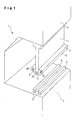
- a tube forming press 1 which consists of a press base 2 and a press upper part 3.
- a bending rate 4 is preferably releasably attached.
- press upper part 3 On press upper part 3 of the molding press 1 a bending rate 4 is preferably releasably attached.
- press upper part 3 On press base 2 is a lower mold 5, here consisting of two moldings 6 and 6 ', arranged, while the bending load is provided with an upper mold 8.
- the upper mold 8 is provided on its underside 9 with a radius which is matched to the inner diameter of the tube to be formed.
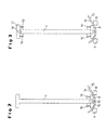
- the upper mold 8 is not rigidly attached to the foot 7 of the bending load value 4, but is - as shown in a first embodiment in Fig. 2 - movably mounted via a joint or a plurality of joints arranged in series 10, the deflection of the upper mold 8 to the longitudinal axis 11 in the direction of arrow 12 or 12 'allow.
- the pivot point 13 of the joint 10 is to avoid bending moments in the vicinity of the surface 14 of a metal sheet to be deformed to a pipe 15. The exact location depends on the criteria to be considered such as surface pressure, bearing size, etc. from.
- the upper mold 7 is brought by both sides of the bending value 4 attached lower spring elements 16 and 16 'in a vertically neutral position.
- FIG. 3 Another embodiment is shown in Fig. 3.
- the articulated attachment of the upper mold 7 is extended here by the bending rate 4 am Head end 17 connected by a further joint 18 with the press upper part 3 is, so a kind of double joint - arrangement with a pivoting movement present at the top and bottom of the bending rate.
- upper Spring elements 19 and 19 ' is also in this attachment an alignment of the bending value 4 in a vertically neutral position in the unloaded state.
Landscapes
- Engineering & Computer Science (AREA)
- Mechanical Engineering (AREA)
- Bending Of Plates, Rods, And Pipes (AREA)
- Heat Treatment Of Articles (AREA)
Abstract
Description
Die Blechtafel wird in einem ersten Schritt an den Längskanten vorgebogen. Die Vorbiegung wird üblicherweise in einer separaten Kantenbiegepresse vorgenommen. Das Vorbiegen der Längskanten erfolgt, damit der Rohrradius bei der Verformung zum Schlitzrohr im Bereich der späteren Naht, dort wo die Längskanten der zu dem Rohr umgebogenen Blechtafel aneinanderstoßen, gleichmäßig ausgeformt ist.
Die vorgebogene Blechtafel wird nun dem eigentlichen Biegeprozess in der Rohrformpresse unterworfen.
Die Rohrformpresse besteht aus einem beweglichen Ober- und Unterteil. Mit dem oberen Teil der Rohrformpresse ist ein senkrecht angeordnetes Biegeschwert verbunden, an dessen Fuß wiederum das obere Formwerkzeug befestigt ist.
Die an der Längsseite vorgebogene Blechtafel wird in einem weiteren Schritt in die Rohrformpresse eingeschoben und dann durch Niederdrücken des Pressenoberteils eine Biegekraft auf die Blechtafel aufgebracht, wobei sich unter der Einwirkung des Biegeschwertes und des von diesem getragenen, oberen Formwerkzeugs eine Verformung der Blechtafel einstellt. Dieser Arbeitsablauf wird mehrmals wiederholt, bis die Blechtafel zu einem Schlitzrohr umgeformt wurde.
Die Zeit zur Herstellung eines Schlitzrohres hängt somit ab von der Anzahl der Hübe der Rohrformpresse und diese wiederum von dem Bereich, der bei einem Hub umgeformt wird. Dieser Umformbereich wird durch die Breite des Formwerkzeuges vorgegeben.
Das am Fuß des Biegeschwertes angebrachte Formwerkzeug besitzt eine Breite, die ein mehrfaches des Querschittes des Biegeschwertes ist und weist einen Formradius auf, der von dem Innenradius des herzustellenden Rohres abhängt. Dieses stempelartige, gerundete Formwerkzeug setzt bei der vertikalen Bewegung asymmetrisch auf der Blechtafel auf, da diese asymmetrisch vorgeformt ist. Hierdurch entsteht ein Biegemoment im Biegeschwert. Damit das Biegeschwert bei solch einer asymmetrischen Belastung nicht ausknickt, wird es mit einem dieses Biegemoment berücksichtigenden Querschnitt ausgelegt.
Beim Herabfahren bzw. Absenken des Biegeschwertes in Richtung auf das untere Formwerkzeug mit der aufgelegten Blechtafel erfolgt mit dem am Fuß befestigten oberen Formwerkzeug ein erster Kontakt zwischen dem Radius des Formwerkzeuges und der Blechtafel auf der Seite des Biegeschwertes, die der vorgebogenen Blechtafelseite abgewandt ist. Durch die gelenkige Lagerung in der horizontalen Längsachse kann sich das obere Formwerkzeug auf der Oberfläche der Blechtafel abrollen und somit einen größeren Verformungsbereich bestreichen, bis die Blechtafel auf z.B. den beiden Leisten des unteren Formwerkzeuges aufliegt. Ab diesem Zeitpunkt beginnt die Verfomung der Blechtafel über den Radius des oberen Formwerkzeuges.
- Figur 1
- eine Rohrformpresse - in einer Ausführung als C-Presse - in vereinfachter perspektivischer Darstellung;
- Figur 2
- eine Seitenansicht eines Biegeschwertes gemäß einer ersten Ausführungsform; und
- Figur 3
- eine Seitenansicht eines Biegeschwertes nach einer zweiten Ausführungsform.
Auf dem Pressenunterteil 2 ist ein unteres Formwerkzeug 5, hier bestehend aus zwei Formleisten 6 und 6', angeordnet, während das Biegeschwert mit einem oberen Formwerkzeug 8 versehen ist. Dieses ist bei der Rohrherstellung nach dem fortschreitenden Form - Verfahren am Fuß 7 des Biegeschwertes 4 auswechselbar befestigt. Das obere Formwerkzeug 8 ist an seiner Unterseite 9 mit einem Radius ausgestattet, der auf den Innendurchmesser des zu formenden Rohres abgestimmt ist.
Das obere Formwerkzeug 8 ist nicht starr am Fuß 7 des Biegeschwertes 4 befestigt, sondern wird - wie in einer ersten Ausführung in Fig. 2 gezeigt - über ein Gelenk oder mehrere in Reihe angeordnete Gelenke 10 beweglich gelagert, die ein Ausweichen des oberen Formwerkzeuges 8 um die Längsachse 11 in Pfeilrichtung 12 oder 12' ermöglichen. Der Drehpunkt 13 des Gelenkes 10 liegt zur Vermeidung von Biegemomenten in der Nähe der Oberfläche 14 einer zu einem Rohr zu verformenden Blechtafel 15. Die genaue Lage hängt von den zu berücksichtigenden Kriterien wie Flächenpressung, Lagergröße, usw. ab. Im unbelasteten Zustand wird das obere Formwerkzeug 7 durch beidseitig des Biegeschwertes 4 angebrachte untere Federelemente 16 und 16' in eine vertikal neutrale Position gebracht.
- 1
- Rohrformpresse
- 2
- Pressenunterteil
- 3
- Pressenoberteil
- 4
- Biegeschwert
- 5
- unteres Formwerkzeug
- 6 6'
- Formleisten
- 7
- Fuß
- 8
- oberes Formwerkzeug
- 9
- Unterseite
- 10
- Drehgelenk
- 11
- Längsachse
- 12 12'
- Pfeil Ausweichrichtung
- 13
- Drehachse
- 14
- Oberfläche
- 15
- Blechtafel
- 16
- untere Federelemente
- 17
- Kopfende
- 18
- Drehgelenk
- 19 19'
- obere Federelemente
Claims (5)
- Vorrichtung zur Herstellung von Rohren aus vorgebogenen Blechtafeln (15), bestehend aus einer Rohrformpresse (1) mit einem am Pressenoberteil (3) befestigten Biegeschwert (4), an dessen Fuß (7) ein oberes Formwerkzeug (8) angeordnet ist, und einem Pressenunterteil (2) mit einem unteren Formwerkzeug (5),
dadurch gekennzeichnet, dass das obere Formwerkzeug (8) gelenkig gelagert ist. - Vorrichtung nach Anspruch 1,
dadurch gekennzeichnet, dass das obere Formwerkzeug (8) am Fuß (7) des Biegeschwertes (4) durch Drehgelenke (10) befestigt ist. - Vorrichtung nach Anspruch 1 oder 2,
dadurch gekennzeichnet, dass das Biegeschwert (4) an seinem Kopfende (17) durch Gelenke (18) am Pressenoberteil (3) gelagert ist. - Vorrichtung nach einem der Ansprüche 1 bis 3,
dadurch gekennzeichnet, dass die Drehachse (13) des oberen Formwerkzeuges (8) benachbart zur Oberfläche (4) der Blechtafel (15) vorgesehen ist. - Vorrichtung nach einem der Ansprüche 1 bis 4,
dadurch gekennzeichnet, dass das obere Formwerkzeug (8) und / oder das Biegeschwert (4) im Bereich ihrer Gelenke (10,18) kraftbeaufschlagt sind.
Applications Claiming Priority (2)
| Application Number | Priority Date | Filing Date | Title |
|---|---|---|---|
| DE10232098 | 2002-07-15 | ||
| DE10232098A DE10232098B4 (de) | 2002-07-15 | 2002-07-15 | Vorrichtung zum Herstellen von Rohren aus Blechtafeln |
Publications (3)
| Publication Number | Publication Date |
|---|---|
| EP1382402A2 true EP1382402A2 (de) | 2004-01-21 |
| EP1382402A3 EP1382402A3 (de) | 2005-03-09 |
| EP1382402B1 EP1382402B1 (de) | 2006-09-20 |
Family
ID=29761985
Family Applications (1)
| Application Number | Title | Priority Date | Filing Date |
|---|---|---|---|
| EP03015232A Expired - Lifetime EP1382402B1 (de) | 2002-07-15 | 2003-07-05 | Vorrichtung zum Herstellen von Rohren aus Blechtafeln |
Country Status (5)
| Country | Link |
|---|---|
| US (1) | US7004005B2 (de) |
| EP (1) | EP1382402B1 (de) |
| JP (1) | JP4002865B2 (de) |
| AT (1) | ATE340039T1 (de) |
| DE (2) | DE10232098B4 (de) |
Cited By (7)
| Publication number | Priority date | Publication date | Assignee | Title |
|---|---|---|---|---|
| WO2009023973A1 (de) * | 2007-08-21 | 2009-02-26 | Soutec Soudronic Ag | Vorrichtung und verfahren zum formen eines rohres aus einem blech |
| EP2077165A1 (de) * | 2008-01-03 | 2009-07-08 | EISENBAU KRÄMER mbH | Blechbiegemaschine |
| DE102011053676A1 (de) | 2011-09-16 | 2013-03-21 | EISENBAU KRäMER GMBH | Rohrbiegemaschine |
| CN105246613A (zh) * | 2013-05-24 | 2016-01-13 | 杰富意钢铁株式会社 | 钢管的制造方法 |
| CN107803412A (zh) * | 2017-11-27 | 2018-03-16 | 安徽东海机床制造有限公司 | 一种框式折弯机及其应用 |
| CN107855382A (zh) * | 2017-11-27 | 2018-03-30 | 安徽东海机床制造有限公司 | 一种圆形工件的折弯加工方法 |
| CN112872130A (zh) * | 2021-01-19 | 2021-06-01 | 陈玉梅 | 一种工业用钢管折弯装置 |
Families Citing this family (14)
| Publication number | Priority date | Publication date | Assignee | Title |
|---|---|---|---|---|
| DE202007007517U1 (de) * | 2007-02-16 | 2007-08-09 | Siempelkamp Maschinen- Und Anlagenbau Gmbh & Co. Kg | Presse |
| JP5393358B2 (ja) * | 2009-09-08 | 2014-01-22 | 住友重機械工業株式会社 | 板曲げプレス |
| DE102011009660B4 (de) | 2011-01-27 | 2013-05-29 | Sms Meer Gmbh | Vorrichtung und Verfahren zum Umformen von Flachprodukten in Schlitzrohre oder Rohrvorprodukte |
| DE102011007396A1 (de) | 2011-04-14 | 2012-10-18 | Ing. Erich Pfeiffer Gmbh | Austragkopf für eine Tube und Tube mit Austragkopf |
| CN104271279B (zh) * | 2012-08-09 | 2016-12-07 | 杰富意钢铁株式会社 | 钢管的制造方法 |
| CN105246608B (zh) * | 2013-05-29 | 2018-01-02 | 杰富意钢铁株式会社 | 焊接钢管的制造方法 |
| JP6262166B2 (ja) | 2014-03-31 | 2018-01-17 | Jfeスチール株式会社 | ベンディングプレス成形用金型 |
| DE102014116192B4 (de) * | 2014-11-06 | 2025-07-17 | Siempelkamp Maschinen- Und Anlagenbau Gmbh | Rohrbiegepresse |
| CN106238520A (zh) * | 2016-08-31 | 2016-12-21 | 陈富强 | 焊带折弯机的改进折弯块 |
| DE102016219706A1 (de) | 2016-10-11 | 2018-04-12 | Sms Group Gmbh | Formpresse mit Biegeschwert |
| JP6721108B2 (ja) | 2017-03-15 | 2020-07-08 | Jfeスチール株式会社 | プレス金型及び鋼管の製造方法 |
| CN108580621A (zh) * | 2018-06-04 | 2018-09-28 | 北京京诚之星科技开发有限公司 | 一种波纹板模压起弧机 |
| JP6791397B2 (ja) | 2018-09-14 | 2020-11-25 | Jfeスチール株式会社 | 鋼管の製造方法及びプレス金型 |
| CN112404164A (zh) * | 2020-11-10 | 2021-02-26 | 上海宝冶集团有限公司 | 方管压制成形的工艺方法 |
Family Cites Families (14)
| Publication number | Priority date | Publication date | Assignee | Title |
|---|---|---|---|---|
| US1914979A (en) * | 1931-03-21 | 1933-06-20 | Bendix Brake Co | Riveting mechanism |
| US2562565A (en) * | 1947-03-28 | 1951-07-31 | Albert W Merk | Electro-type straightener with rocking plate sections |
| US2763924A (en) * | 1953-12-29 | 1956-09-25 | Bellometti Ugo | Process and apparatus for manufacturing tubes, tanks and hollow bodies generally from metal in sheet or band form |
| DE1183465B (de) * | 1962-02-01 | 1964-12-17 | Siempelkamp Gmbh & Co | Biegewerkzeug zum Herstellen von zylindrischen oder konischen Rohren aus ebenen Blechzuschnitten |
| FI45165C (fi) * | 1970-07-21 | 1972-04-10 | Fiskars Ab Oy | Alasinjärjestely taontakoneissa koneen alustaan kohdistuvien iskujen v aimentamiseksi. |
| DE2218419C2 (de) * | 1972-04-13 | 1973-10-25 | Mannesmann-Meer Ag, 4050 Moenchengladbach | Biegepresse, insbesondere fur eine Anlage zum Herstellen von Groß rohren |
| DE2402190C3 (de) * | 1974-01-17 | 1978-03-02 | Mitsubishi Jukogyo K.K., Tokio | Vorrichtung zum Biegen von Stahlblechen bzw. -platten |
| JPS5841621A (ja) * | 1981-09-07 | 1983-03-10 | Mitsubishi Heavy Ind Ltd | ポンチヘツドの姿勢保持方法 |
| JPS59199116A (ja) * | 1983-04-28 | 1984-11-12 | Nippon Kokan Kk <Nkk> | Uoe造管法に使用するuプレス用パンチ装置 |
| JPS59209425A (ja) * | 1983-05-12 | 1984-11-28 | Nippon Kokan Kk <Nkk> | Uoe鋼管製造プロセス用uプレス工具 |
| JPS62142026A (ja) * | 1985-12-16 | 1987-06-25 | Kawasaki Steel Corp | 管体成形機 |
| NL8600462A (nl) * | 1986-02-25 | 1987-09-16 | Philips Nv | Inrichting voor het samenpersen van een stapel boven elkaar liggende foelies. |
| DE4138285C2 (de) * | 1991-11-21 | 1994-04-07 | M & S Brugg Ag Brugg | Hydraulische Abkantpresse |
| JP2001252722A (ja) * | 2000-03-09 | 2001-09-18 | Sumitomo Metal Ind Ltd | Uプレス工具およびuoe鋼管の製造法 |
-
2002
- 2002-07-15 DE DE10232098A patent/DE10232098B4/de not_active Expired - Fee Related
-
2003
- 2003-07-05 AT AT03015232T patent/ATE340039T1/de not_active IP Right Cessation
- 2003-07-05 EP EP03015232A patent/EP1382402B1/de not_active Expired - Lifetime
- 2003-07-05 DE DE50305093T patent/DE50305093D1/de not_active Expired - Lifetime
- 2003-07-10 JP JP2003194865A patent/JP4002865B2/ja not_active Expired - Lifetime
- 2003-07-11 US US10/617,577 patent/US7004005B2/en not_active Expired - Lifetime
Cited By (8)
| Publication number | Priority date | Publication date | Assignee | Title |
|---|---|---|---|---|
| WO2009023973A1 (de) * | 2007-08-21 | 2009-02-26 | Soutec Soudronic Ag | Vorrichtung und verfahren zum formen eines rohres aus einem blech |
| EP2077165A1 (de) * | 2008-01-03 | 2009-07-08 | EISENBAU KRÄMER mbH | Blechbiegemaschine |
| DE102011053676A1 (de) | 2011-09-16 | 2013-03-21 | EISENBAU KRäMER GMBH | Rohrbiegemaschine |
| DE102011053676B4 (de) * | 2011-09-16 | 2016-09-08 | EISENBAU KRäMER GMBH | Rohrbiegemaschine |
| CN105246613A (zh) * | 2013-05-24 | 2016-01-13 | 杰富意钢铁株式会社 | 钢管的制造方法 |
| CN107803412A (zh) * | 2017-11-27 | 2018-03-16 | 安徽东海机床制造有限公司 | 一种框式折弯机及其应用 |
| CN107855382A (zh) * | 2017-11-27 | 2018-03-30 | 安徽东海机床制造有限公司 | 一种圆形工件的折弯加工方法 |
| CN112872130A (zh) * | 2021-01-19 | 2021-06-01 | 陈玉梅 | 一种工业用钢管折弯装置 |
Also Published As
| Publication number | Publication date |
|---|---|
| JP2004082219A (ja) | 2004-03-18 |
| EP1382402A3 (de) | 2005-03-09 |
| US7004005B2 (en) | 2006-02-28 |
| US20040055356A1 (en) | 2004-03-25 |
| ATE340039T1 (de) | 2006-10-15 |
| DE10232098B4 (de) | 2004-05-06 |
| DE50305093D1 (de) | 2006-11-02 |
| EP1382402B1 (de) | 2006-09-20 |
| DE10232098A1 (de) | 2004-02-05 |
| JP4002865B2 (ja) | 2007-11-07 |
Similar Documents
| Publication | Publication Date | Title |
|---|---|---|
| EP1382402B1 (de) | Vorrichtung zum Herstellen von Rohren aus Blechtafeln | |
| DE3709555C2 (de) | Abkantpresse | |
| CH660398A5 (de) | Abstandhalterrahmen fuer isolierglasscheiben sowie verfahren zur herstellung desselben und vorrichtung zur durchfuehrung des verfahrens. | |
| DE102007012316B9 (de) | Verfahren und Anbiegepresse zum Anbiegen der Randstreifen eines zu einem Schlitzrohr zu formenden ebenen Bleches | |
| DE2953278C2 (de) | ||
| EP1112788B1 (de) | Vorrichtung zum schrittweisen Biegen von Metallblech oder Metallbändern | |
| DE3527558C2 (de) | ||
| AT512174A4 (de) | Biegepresse mit verstellbarem balkenelement | |
| DE3137616C2 (de) | ||
| EP0497780B1 (de) | Verfahren zum gegenläufigen biegen eines bleches | |
| DE3105351C2 (de) | Vorrichtung zum Biegen des Längskantenbereichs einer Stahlplatte | |
| DE3810611C2 (de) | ||
| DE2727287C2 (de) | Vorrichtung zum Biegen profilierter Platten | |
| EP0109031B1 (de) | Verfahren und Werkzeug zum Biegen von Randabschnitten eines Bleches | |
| DE4423487C2 (de) | Vorrichtung zum Biegen von Hohlprofilen mit nicht allseitig geschlossenen Profilquerschnitten | |
| DE2800823A1 (de) | Verfahren und vorrichtung zum formen von rohren o.dgl. | |
| DE3736394A1 (de) | Vorrichtung zum herstellen von traegern fuer bauzwecke und dergl. | |
| EP0313760A2 (de) | Vorrichtung zum Herstellen von Trägern für Bauzwecke und dergl. | |
| EP1372877A1 (de) | Verfahren zum strangpressen und strangpressanlage, insbesondere zum herstellen von gekrümmten strangpressprodukten | |
| EP1324841B1 (de) | Vorrichtung zum biegen einer materialbahn | |
| EP0358019B1 (de) | Verfahren und Vorrichtung zur Herstellung von Einbänden oder dergleichen | |
| DE2340138C2 (de) | Verfahren und Vorrichtung zum Herstellen von Wellengittern aus Endlosdraht für Gitterträger | |
| DE2319447B2 (de) | Vorrichtung zum Runden von Blechzuschnitten | |
| CH624318A5 (en) | Method and apparatus for bending a corrugated sheet and a corrugated sheet bent by this method | |
| AT352499B (de) | Verfahren und vorrichtung zum biegen eines profilierten bleches |
Legal Events
| Date | Code | Title | Description |
|---|---|---|---|
| PUAI | Public reference made under article 153(3) epc to a published international application that has entered the european phase |
Free format text: ORIGINAL CODE: 0009012 |
|
| AK | Designated contracting states |
Kind code of ref document: A2 Designated state(s): AT BE BG CH CY CZ DE DK EE ES FI FR GB GR HU IE IT LI LU MC NL PT RO SE SI SK TR |
|
| AX | Request for extension of the european patent |
Extension state: AL LT LV MK |
|
| PUAL | Search report despatched |
Free format text: ORIGINAL CODE: 0009013 |
|
| AK | Designated contracting states |
Kind code of ref document: A3 Designated state(s): AT BE BG CH CY CZ DE DK EE ES FI FR GB GR HU IE IT LI LU MC NL PT RO SE SI SK TR |
|
| AX | Request for extension of the european patent |
Extension state: AL LT LV MK |
|
| 17P | Request for examination filed |
Effective date: 20050805 |
|
| AKX | Designation fees paid |
Designated state(s): AT BE BG CH CY CZ DE DK EE ES FI FR GB GR HU IE IT LI LU MC NL PT RO SE SI SK TR |
|
| GRAP | Despatch of communication of intention to grant a patent |
Free format text: ORIGINAL CODE: EPIDOSNIGR1 |
|
| GRAS | Grant fee paid |
Free format text: ORIGINAL CODE: EPIDOSNIGR3 |
|
| GRAA | (expected) grant |
Free format text: ORIGINAL CODE: 0009210 |
|
| AK | Designated contracting states |
Kind code of ref document: B1 Designated state(s): AT BE BG CH CY CZ DE DK EE ES FI FR GB GR HU IE IT LI LU MC NL PT RO SE SI SK TR |
|
| PG25 | Lapsed in a contracting state [announced via postgrant information from national office to epo] |
Ref country code: SI Free format text: LAPSE BECAUSE OF FAILURE TO SUBMIT A TRANSLATION OF THE DESCRIPTION OR TO PAY THE FEE WITHIN THE PRESCRIBED TIME-LIMIT Effective date: 20060920 Ref country code: IT Free format text: LAPSE BECAUSE OF FAILURE TO SUBMIT A TRANSLATION OF THE DESCRIPTION OR TO PAY THE FEE WITHIN THE PRESCRIBED TIME-LIMIT;WARNING: LAPSES OF ITALIAN PATENTS WITH EFFECTIVE DATE BEFORE 2007 MAY HAVE OCCURRED AT ANY TIME BEFORE 2007. THE CORRECT EFFECTIVE DATE MAY BE DIFFERENT FROM THE ONE RECORDED. Effective date: 20060920 Ref country code: SK Free format text: LAPSE BECAUSE OF FAILURE TO SUBMIT A TRANSLATION OF THE DESCRIPTION OR TO PAY THE FEE WITHIN THE PRESCRIBED TIME-LIMIT Effective date: 20060920 Ref country code: NL Free format text: LAPSE BECAUSE OF FAILURE TO SUBMIT A TRANSLATION OF THE DESCRIPTION OR TO PAY THE FEE WITHIN THE PRESCRIBED TIME-LIMIT Effective date: 20060920 Ref country code: FI Free format text: LAPSE BECAUSE OF FAILURE TO SUBMIT A TRANSLATION OF THE DESCRIPTION OR TO PAY THE FEE WITHIN THE PRESCRIBED TIME-LIMIT Effective date: 20060920 Ref country code: IE Free format text: LAPSE BECAUSE OF FAILURE TO SUBMIT A TRANSLATION OF THE DESCRIPTION OR TO PAY THE FEE WITHIN THE PRESCRIBED TIME-LIMIT Effective date: 20060920 |
|
| REG | Reference to a national code |
Ref country code: GB Ref legal event code: FG4D Free format text: NOT ENGLISH |
|
| REG | Reference to a national code |
Ref country code: CH Ref legal event code: EP |
|
| REG | Reference to a national code |
Ref country code: CH Ref legal event code: NV Representative=s name: WILLIAM BLANC & CIE CONSEILS EN PROPRIETE INDUSTRI |
|
| REG | Reference to a national code |
Ref country code: IE Ref legal event code: FG4D Free format text: LANGUAGE OF EP DOCUMENT: GERMAN |
|
| REF | Corresponds to: |
Ref document number: 50305093 Country of ref document: DE Date of ref document: 20061102 Kind code of ref document: P |
|
| REG | Reference to a national code |
Ref country code: DE Ref legal event code: R096 Ref document number: 50305093 Country of ref document: DE Effective date: 20061102 |
|
| REG | Reference to a national code |
Ref country code: RO Ref legal event code: EPE |
|
| PG25 | Lapsed in a contracting state [announced via postgrant information from national office to epo] |
Ref country code: SE Free format text: LAPSE BECAUSE OF FAILURE TO SUBMIT A TRANSLATION OF THE DESCRIPTION OR TO PAY THE FEE WITHIN THE PRESCRIBED TIME-LIMIT Effective date: 20061220 Ref country code: DK Free format text: LAPSE BECAUSE OF FAILURE TO SUBMIT A TRANSLATION OF THE DESCRIPTION OR TO PAY THE FEE WITHIN THE PRESCRIBED TIME-LIMIT Effective date: 20061220 Ref country code: BG Free format text: LAPSE BECAUSE OF FAILURE TO SUBMIT A TRANSLATION OF THE DESCRIPTION OR TO PAY THE FEE WITHIN THE PRESCRIBED TIME-LIMIT Effective date: 20061220 |
|
| PG25 | Lapsed in a contracting state [announced via postgrant information from national office to epo] |
Ref country code: ES Free format text: LAPSE BECAUSE OF FAILURE TO SUBMIT A TRANSLATION OF THE DESCRIPTION OR TO PAY THE FEE WITHIN THE PRESCRIBED TIME-LIMIT Effective date: 20061231 |
|
| GBT | Gb: translation of ep patent filed (gb section 77(6)(a)/1977) |
Effective date: 20070103 |
|
| NLV1 | Nl: lapsed or annulled due to failure to fulfill the requirements of art. 29p and 29m of the patents act | ||
| PG25 | Lapsed in a contracting state [announced via postgrant information from national office to epo] |
Ref country code: PT Free format text: LAPSE BECAUSE OF FAILURE TO SUBMIT A TRANSLATION OF THE DESCRIPTION OR TO PAY THE FEE WITHIN THE PRESCRIBED TIME-LIMIT Effective date: 20070312 |
|
| ET | Fr: translation filed | ||
| REG | Reference to a national code |
Ref country code: IE Ref legal event code: FD4D |
|
| REG | Reference to a national code |
Ref country code: CH Ref legal event code: PK Free format text: DER VERTRETEREINTRAG VOM 29.09.06 (WILLIAM BLANC & CIE) Ref country code: CH Ref legal event code: NV Representative=s name: SCHMAUDER & PARTNER AG PATENTANWALTSBUERO |
|
| PLBE | No opposition filed within time limit |
Free format text: ORIGINAL CODE: 0009261 |
|
| STAA | Information on the status of an ep patent application or granted ep patent |
Free format text: STATUS: NO OPPOSITION FILED WITHIN TIME LIMIT |
|
| 26N | No opposition filed |
Effective date: 20070621 |
|
| REG | Reference to a national code |
Ref country code: DE Ref legal event code: R097 Ref document number: 50305093 Country of ref document: DE Effective date: 20070620 |
|
| BERE | Be: lapsed |
Owner name: SMS MEER G.M.B.H. Effective date: 20070731 |
|
| PG25 | Lapsed in a contracting state [announced via postgrant information from national office to epo] |
Ref country code: MC Free format text: LAPSE BECAUSE OF NON-PAYMENT OF DUE FEES Effective date: 20070731 Ref country code: GR Free format text: LAPSE BECAUSE OF FAILURE TO SUBMIT A TRANSLATION OF THE DESCRIPTION OR TO PAY THE FEE WITHIN THE PRESCRIBED TIME-LIMIT Effective date: 20061221 |
|
| PG25 | Lapsed in a contracting state [announced via postgrant information from national office to epo] |
Ref country code: EE Free format text: LAPSE BECAUSE OF FAILURE TO SUBMIT A TRANSLATION OF THE DESCRIPTION OR TO PAY THE FEE WITHIN THE PRESCRIBED TIME-LIMIT Effective date: 20060920 |
|
| PG25 | Lapsed in a contracting state [announced via postgrant information from national office to epo] |
Ref country code: BE Free format text: LAPSE BECAUSE OF NON-PAYMENT OF DUE FEES Effective date: 20070731 |
|
| PG25 | Lapsed in a contracting state [announced via postgrant information from national office to epo] |
Ref country code: AT Free format text: LAPSE BECAUSE OF NON-PAYMENT OF DUE FEES Effective date: 20070705 |
|
| REG | Reference to a national code |
Ref country code: CH Ref legal event code: PCAR Free format text: SCHMAUDER & PARTNER AG PATENT- UND MARKENANWAELTE VSP;ZWAENGIWEG 7;8038 ZUERICH (CH) |
|
| PG25 | Lapsed in a contracting state [announced via postgrant information from national office to epo] |
Ref country code: CY Free format text: LAPSE BECAUSE OF FAILURE TO SUBMIT A TRANSLATION OF THE DESCRIPTION OR TO PAY THE FEE WITHIN THE PRESCRIBED TIME-LIMIT Effective date: 20060920 Ref country code: LU Free format text: LAPSE BECAUSE OF NON-PAYMENT OF DUE FEES Effective date: 20070705 |
|
| PG25 | Lapsed in a contracting state [announced via postgrant information from national office to epo] |
Ref country code: HU Free format text: LAPSE BECAUSE OF FAILURE TO SUBMIT A TRANSLATION OF THE DESCRIPTION OR TO PAY THE FEE WITHIN THE PRESCRIBED TIME-LIMIT Effective date: 20070321 |
|
| REG | Reference to a national code |
Ref country code: DE Ref legal event code: R082 Ref document number: 50305093 Country of ref document: DE Representative=s name: HEMMERICH & KOLLEGEN PATENTANWAELTE, DE Ref country code: DE Ref legal event code: R082 Ref document number: 50305093 Country of ref document: DE Representative=s name: HEMMERICH & KOLLEGEN, DE Ref country code: DE Ref legal event code: R081 Ref document number: 50305093 Country of ref document: DE Owner name: SMS GROUP GMBH, DE Free format text: FORMER OWNER: SMS MEER GMBH, 41069 MOENCHENGLADBACH, DE |
|
| REG | Reference to a national code |
Ref country code: FR Ref legal event code: PLFP Year of fee payment: 14 |
|
| REG | Reference to a national code |
Ref country code: FR Ref legal event code: PLFP Year of fee payment: 15 |
|
| REG | Reference to a national code |
Ref country code: FR Ref legal event code: PLFP Year of fee payment: 16 |
|
| PGFP | Annual fee paid to national office [announced via postgrant information from national office to epo] |
Ref country code: RO Payment date: 20220629 Year of fee payment: 20 |
|
| PGFP | Annual fee paid to national office [announced via postgrant information from national office to epo] |
Ref country code: TR Payment date: 20220704 Year of fee payment: 20 Ref country code: IT Payment date: 20220726 Year of fee payment: 20 Ref country code: GB Payment date: 20220722 Year of fee payment: 20 Ref country code: DE Payment date: 20220620 Year of fee payment: 20 Ref country code: CZ Payment date: 20220707 Year of fee payment: 20 |
|
| PGFP | Annual fee paid to national office [announced via postgrant information from national office to epo] |
Ref country code: FR Payment date: 20220720 Year of fee payment: 20 |
|
| PGFP | Annual fee paid to national office [announced via postgrant information from national office to epo] |
Ref country code: CH Payment date: 20220725 Year of fee payment: 20 |
|
| REG | Reference to a national code |
Ref country code: DE Ref legal event code: R071 Ref document number: 50305093 Country of ref document: DE |
|
| REG | Reference to a national code |
Ref country code: CH Ref legal event code: PL |
|
| REG | Reference to a national code |
Ref country code: GB Ref legal event code: PE20 Expiry date: 20230704 |
|
| PG25 | Lapsed in a contracting state [announced via postgrant information from national office to epo] |
Ref country code: CZ Free format text: LAPSE BECAUSE OF EXPIRATION OF PROTECTION Effective date: 20230705 |
|
| P01 | Opt-out of the competence of the unified patent court (upc) registered |
Effective date: 20230707 |
|
| PG25 | Lapsed in a contracting state [announced via postgrant information from national office to epo] |
Ref country code: GB Free format text: LAPSE BECAUSE OF EXPIRATION OF PROTECTION Effective date: 20230704 |