EP1341166A2 - Tête optique aux différentes longueurs d'onde - Google Patents
Tête optique aux différentes longueurs d'onde Download PDFInfo
- Publication number
- EP1341166A2 EP1341166A2 EP03251102A EP03251102A EP1341166A2 EP 1341166 A2 EP1341166 A2 EP 1341166A2 EP 03251102 A EP03251102 A EP 03251102A EP 03251102 A EP03251102 A EP 03251102A EP 1341166 A2 EP1341166 A2 EP 1341166A2
- Authority
- EP
- European Patent Office
- Prior art keywords
- light
- recording medium
- light source
- optical recording
- optical
- Prior art date
- Legal status (The legal status is an assumption and is not a legal conclusion. Google has not performed a legal analysis and makes no representation as to the accuracy of the status listed.)
- Granted
Links
Images


Classifications
-
- G—PHYSICS
- G11—INFORMATION STORAGE
- G11B—INFORMATION STORAGE BASED ON RELATIVE MOVEMENT BETWEEN RECORD CARRIER AND TRANSDUCER
- G11B7/00—Recording or reproducing by optical means, e.g. recording using a thermal beam of optical radiation by modifying optical properties or the physical structure, reproducing using an optical beam at lower power by sensing optical properties; Record carriers therefor
- G11B7/12—Heads, e.g. forming of the optical beam spot or modulation of the optical beam
- G11B7/135—Means for guiding the beam from the source to the record carrier or from the record carrier to the detector
- G11B7/1353—Diffractive elements, e.g. holograms or gratings
-
- G—PHYSICS
- G11—INFORMATION STORAGE
- G11B—INFORMATION STORAGE BASED ON RELATIVE MOVEMENT BETWEEN RECORD CARRIER AND TRANSDUCER
- G11B7/00—Recording or reproducing by optical means, e.g. recording using a thermal beam of optical radiation by modifying optical properties or the physical structure, reproducing using an optical beam at lower power by sensing optical properties; Record carriers therefor
- G11B7/12—Heads, e.g. forming of the optical beam spot or modulation of the optical beam
- G11B7/123—Integrated head arrangements, e.g. with source and detectors mounted on the same substrate
-
- G—PHYSICS
- G11—INFORMATION STORAGE
- G11B—INFORMATION STORAGE BASED ON RELATIVE MOVEMENT BETWEEN RECORD CARRIER AND TRANSDUCER
- G11B7/00—Recording or reproducing by optical means, e.g. recording using a thermal beam of optical radiation by modifying optical properties or the physical structure, reproducing using an optical beam at lower power by sensing optical properties; Record carriers therefor
- G11B7/12—Heads, e.g. forming of the optical beam spot or modulation of the optical beam
- G11B7/125—Optical beam sources therefor, e.g. laser control circuitry specially adapted for optical storage devices; Modulators, e.g. means for controlling the size or intensity of optical spots or optical traces
- G11B7/127—Lasers; Multiple laser arrays
-
- G—PHYSICS
- G11—INFORMATION STORAGE
- G11B—INFORMATION STORAGE BASED ON RELATIVE MOVEMENT BETWEEN RECORD CARRIER AND TRANSDUCER
- G11B7/00—Recording or reproducing by optical means, e.g. recording using a thermal beam of optical radiation by modifying optical properties or the physical structure, reproducing using an optical beam at lower power by sensing optical properties; Record carriers therefor
- G11B7/12—Heads, e.g. forming of the optical beam spot or modulation of the optical beam
- G11B7/13—Optical detectors therefor
- G11B7/131—Arrangement of detectors in a multiple array
-
- G—PHYSICS
- G11—INFORMATION STORAGE
- G11B—INFORMATION STORAGE BASED ON RELATIVE MOVEMENT BETWEEN RECORD CARRIER AND TRANSDUCER
- G11B7/00—Recording or reproducing by optical means, e.g. recording using a thermal beam of optical radiation by modifying optical properties or the physical structure, reproducing using an optical beam at lower power by sensing optical properties; Record carriers therefor
- G11B7/12—Heads, e.g. forming of the optical beam spot or modulation of the optical beam
- G11B7/135—Means for guiding the beam from the source to the record carrier or from the record carrier to the detector
- G11B7/1365—Separate or integrated refractive elements, e.g. wave plates
- G11B7/1369—Active plates, e.g. liquid crystal panels or electrostrictive elements
-
- G—PHYSICS
- G11—INFORMATION STORAGE
- G11B—INFORMATION STORAGE BASED ON RELATIVE MOVEMENT BETWEEN RECORD CARRIER AND TRANSDUCER
- G11B7/00—Recording or reproducing by optical means, e.g. recording using a thermal beam of optical radiation by modifying optical properties or the physical structure, reproducing using an optical beam at lower power by sensing optical properties; Record carriers therefor
- G11B7/12—Heads, e.g. forming of the optical beam spot or modulation of the optical beam
- G11B7/135—Means for guiding the beam from the source to the record carrier or from the record carrier to the detector
- G11B7/139—Numerical aperture control means
-
- G—PHYSICS
- G11—INFORMATION STORAGE
- G11B—INFORMATION STORAGE BASED ON RELATIVE MOVEMENT BETWEEN RECORD CARRIER AND TRANSDUCER
- G11B7/00—Recording or reproducing by optical means, e.g. recording using a thermal beam of optical radiation by modifying optical properties or the physical structure, reproducing using an optical beam at lower power by sensing optical properties; Record carriers therefor
- G11B7/12—Heads, e.g. forming of the optical beam spot or modulation of the optical beam
- G11B7/135—Means for guiding the beam from the source to the record carrier or from the record carrier to the detector
- G11B7/1392—Means for controlling the beam wavefront, e.g. for correction of aberration
- G11B7/13925—Means for controlling the beam wavefront, e.g. for correction of aberration active, e.g. controlled by electrical or mechanical means
-
- G—PHYSICS
- G02—OPTICS
- G02F—OPTICAL DEVICES OR ARRANGEMENTS FOR THE CONTROL OF LIGHT BY MODIFICATION OF THE OPTICAL PROPERTIES OF THE MEDIA OF THE ELEMENTS INVOLVED THEREIN; NON-LINEAR OPTICS; FREQUENCY-CHANGING OF LIGHT; OPTICAL LOGIC ELEMENTS; OPTICAL ANALOGUE/DIGITAL CONVERTERS
- G02F1/00—Devices or arrangements for the control of the intensity, colour, phase, polarisation or direction of light arriving from an independent light source, e.g. switching, gating or modulating; Non-linear optics
- G02F1/01—Devices or arrangements for the control of the intensity, colour, phase, polarisation or direction of light arriving from an independent light source, e.g. switching, gating or modulating; Non-linear optics for the control of the intensity, phase, polarisation or colour
- G02F1/13—Devices or arrangements for the control of the intensity, colour, phase, polarisation or direction of light arriving from an independent light source, e.g. switching, gating or modulating; Non-linear optics for the control of the intensity, phase, polarisation or colour based on liquid crystals, e.g. single liquid crystal display cells
- G02F1/133—Constructional arrangements; Operation of liquid crystal cells; Circuit arrangements
- G02F1/1333—Constructional arrangements; Manufacturing methods
- G02F1/1343—Electrodes
- G02F1/134309—Electrodes characterised by their geometrical arrangement
-
- G—PHYSICS
- G02—OPTICS
- G02F—OPTICAL DEVICES OR ARRANGEMENTS FOR THE CONTROL OF LIGHT BY MODIFICATION OF THE OPTICAL PROPERTIES OF THE MEDIA OF THE ELEMENTS INVOLVED THEREIN; NON-LINEAR OPTICS; FREQUENCY-CHANGING OF LIGHT; OPTICAL LOGIC ELEMENTS; OPTICAL ANALOGUE/DIGITAL CONVERTERS
- G02F2203/00—Function characteristic
- G02F2203/18—Function characteristic adaptive optics, e.g. wavefront correction
-
- G—PHYSICS
- G11—INFORMATION STORAGE
- G11B—INFORMATION STORAGE BASED ON RELATIVE MOVEMENT BETWEEN RECORD CARRIER AND TRANSDUCER
- G11B7/00—Recording or reproducing by optical means, e.g. recording using a thermal beam of optical radiation by modifying optical properties or the physical structure, reproducing using an optical beam at lower power by sensing optical properties; Record carriers therefor
- G11B2007/0003—Recording, reproducing or erasing systems characterised by the structure or type of the carrier
- G11B2007/0006—Recording, reproducing or erasing systems characterised by the structure or type of the carrier adapted for scanning different types of carrier, e.g. CD & DVD
-
- G—PHYSICS
- G11—INFORMATION STORAGE
- G11B—INFORMATION STORAGE BASED ON RELATIVE MOVEMENT BETWEEN RECORD CARRIER AND TRANSDUCER
- G11B7/00—Recording or reproducing by optical means, e.g. recording using a thermal beam of optical radiation by modifying optical properties or the physical structure, reproducing using an optical beam at lower power by sensing optical properties; Record carriers therefor
- G11B2007/0003—Recording, reproducing or erasing systems characterised by the structure or type of the carrier
- G11B2007/0009—Recording, reproducing or erasing systems characterised by the structure or type of the carrier for carriers having data stored in three dimensions, e.g. volume storage
- G11B2007/0013—Recording, reproducing or erasing systems characterised by the structure or type of the carrier for carriers having data stored in three dimensions, e.g. volume storage for carriers having multiple discrete layers
Definitions
- Optical recording media such as a CD with a storage capacity of 0.65 GB and a DVD with a storage capacity of 4.7 GB, are spreading as means to store data of image information, voice information, or computer data. Further, demands for a further improvement in recording density and storage capacity become stronger in recent years. Specifically, the necessity for as storage capacity, such as for 22 GB by which a high-definition television program can be stored for two hours for recording one movie program, or for 44 GB by which the same can be stored for four hours for recording a sport relay broadcast or so.
- the anticipated problems include, for example, those caused by a manufacture error of a lens, an even-th aberration which means a distortion in an isotropic wavefront with respect to the optical axis produced according to a manufacture error of a lens applied, a thickness error of a transparent substrate of an optical recording medium loaded, an odd-th aberration which means a distortion in an anisotropic wavefront with respect to the optical axis generated by an inclination of the optical recording medium, or so.
- a beam emitted from a light source is focused onto an optical recording medium in one light path, while a light reflected from the optical recording medium is detected by a light detecting device in another light path.
- a light detecting device in another light path.
- a system using a light source of a blue wavelength zone in an operating wavelength of 407 nm ⁇ 10 nm and an object lens of NA of 0.85 is such that a setting is made on the optical-incident side substrate thickness of an optical recording medium as being 0.1 mm, and, thereby, an aberration increase amount occurring due to reduction in wavelength or increase in NA may be compensated, and, thus, even if there occurs a wavefront degradation caused due to an inclination change of the optical recording medium, it may be kept not more than 0.07 ⁇ .
- a manufacture error in products of optical devices especially, as an object lens, used in an optical pickup may cause a problem concerning an aberration.
- a thickness error, a refractive-index error, a curvature radius error and so forth in the lens may cause generation of the even-th aberration, while a tilt or eccentricity of the lens may cause the odd-th aberration.
- Another problem is such that users still have conventional recording medium such as CDs and DVDs. It is desirable that these conventional optical recording media and new optical recording media according to the above-mentioned new standard should be handled with a single common optical information processing device.
- One easier method of solving this problem is such that an optical pickup according to the conventional standard and an optical pickup according to the new standard are both mounted in one machine separately.
- this method may raise the cost or increase the size of the whole machine.
- problems to be solved occurring when achieving an optical pickup directed to future high-density optical recording media are to reduce aberrations which otherwise increase due to increase in NA or reduction in wavelength, and, also, to achieve a compatibility between the conventional standard and new standard optical.recording media (i.e., of different generations). Further, it is also a problem to be solved to achieve these objects without a remarkable increase in size/costs of the machine.
- spherical aberration occurring in connection with a thickness error of optical recording medium may be reduced by means of improvement in the manufacture accuracy of the optical recording medium.
- coma aberration in connection with an inclination of an optical recording medium may also be reduced by setting the substrate thickness thereof into 0.1 mm, even when the light source of a blue wavelength zone and NA of 0.85 are applied.
- An object of the present invention is to solve these problems, and is to provide an optical information processing apparatus in which, without a remarkable increase of the number of required parts/components of the machine by sharing an optical device such as an aberration correction device, it should be possible to form a satisfactory beam spot on each of a blue-system optical recording medium using a light source with a wavelength of a blue wavelength zone of 407 nm, a DVD-system optical recording medium using a light source with a wavelength of a red wavelength zone of 660 nm and a CD-system optical recording medium using a light source with a wavelength of an infrared wavelength zone of 780 nm.
- a single object lens and a single aberration correction device are provided by which various types of aberrations occurring mainly due to compatible use of these different types of optical recording media can be effectively controlled, or well reduced.
- a satisfactory beam spot can be formed on the optical recording medium in any case with a simple configuration. For example, the divergent state of a beam applied is controlled, a phase shift for canceling out an originally occurring (wavefront/spherical) aberration is provided, or so, whereby the originally occurring aberration can be effectively controlled.
- optical parts/components are used in common for applying these types of optical recording medium, or various optical parts/components may be integrally combined. Also for this reason, a compact optical pickup which can be compatibly applied to the two/three types of optical recording media (two/three generations) is achieved.
- the aberration correction device by applying the aberration correction device, it is also possible to deal with/cope with problems that manufacture errors of optical recording media may cause an aberration, that a variation/fluctuation occurring in the light sources (semiconductor lasers) causes an aberration, that a difference between information recording surfaces in a multi-layer optical recording medium causes an aberration, and so forth.
- an aperture control/switching device which controls a diameter of a beam passing therethrough according to the wavelength applied, it becomes possible to achieve a compatible configuration of optical pickup for the above-mentioned two or three generations of optical recording media, with a simple configuration.
- an elliptic shape of cross section to a beam to be applied to the optical recording medium via the object lens, wherein the miner axis of the elliptic shape corresponds to the tangential direction of the disk-shaped optical recording medium, it is possible to effectively reduce the beam diameter, and, thus, to effectively improve the S/N even when a multi-level recording is performed.
- two types of chromatic aberrations can be effectively controlled or well reduced by generally the same concept.
- a phase correction device is configured such that a desired phase shift is given only on a light of relevant wavelength, while no substantially effect is applied to a light of not relevant wavelength, as the phase shift in this case is made as being an integer multiple of 2 ⁇ .
- a liquid crystal device is applied to the above-mentioned phase correction device or aberration correction device. Then, a concentric pupil radius positions with respect to an optical axis of the optical pickup at which a large phase shift is applied by the liquid crystal device is controlled according to an originally occurring concentric aberration to be controlled.
- the liquid crystal device it becomes possible to easily control the pupil radius position having the large phase shift amount or to easily control the magnitude of the phase shift amount provided to a beam passing therethrough merely by controlling a voltage applied to electrode pattern formed in the liquid crystal device.
- the refractive index thereof can be controlled accordingly, and, thus, the phase shift provided to the passing beam can be controlled accordingly.
- a dynamic control of phase shift provided to the passing beam is archived, and, thus, control of aberration can be performed finely, or with a higher accuracy.
- FIG. 1 is a block diagram showing a general configuration of an optical pickup in a first embodiment of the present invention.
- an optical pickup uses a light source with an operating wavelength of a blue wavelength zone of 407 nm, and an object lens of NA:0.65 for a blue-system (large storage capacity) optical recording medium having an light-incidence-side substrate with a thickness of 0.6 mm, and, also, uses a light source with an operating wavelength of 660 nm and the object lens with NA: 0.65 for a DVD-system optical recording medium having an light-incidence-side substrate with a thickness of 0.6 mm.
- a wavelength selection aperture 204 is added for the object lens 106 for NA: 0.85, and the light-incidence-side substrate having the thickness of 0.1 mm of the optical recording medium 107; and also, a finite DVD's red-system optical system is applied instead of the infinite system such that the incidence beam to the object lens is made to a divergent beam.
- the thus-generated even-th aberration is used for canceling out the above-mentioned chromatic and spherical aberrations. Furthermore, by providing a coupling lens 205 between the light source for DVD and the object lens, the light path for the red-system optical system is shortened.
- the odd-th aberration correction device 502 includes the liquid crystal device and a voltage control device (not shown) to drive the liquid crystal device.
- the liquid crystal device is divided symmetrically in the horizontal direction in the figure at least one side of transparent electrode, and this liquid crystal device is configured so that a voltage can be applied independently between the electrode portion of each division of electrode, and a common electrode.
- each division of the liquid crystal device can be freely controlled to have the refractive index n through a range between n1 and n2 by controlling the above-mentioned voltage.
- both the even-th aberration correction device and the odd-th aberration correction device are provided as an aberration correction device 601.
- a different point from the sixth embodiment is a point that the even-th aberration correction device and the odd-th aberration correction device are realized by a common single device.
- the even-th aberration detection device a sensor which detects the substrate thickness of the optical recording medium 107 may be provided, and, also, the odd-th aberration detection may have a configuration of using the above-mentioned beam splitting device. Furthermore, it is also possible to provide both the even-th aberration detection device and the odd-th aberration detection device on light paths separate from the optical pickup itself (not shown).
- a blue-system (large storage capacity) optical recording medium while a light source with an operating wavelength of an infrared wavelength zone of 780 nm and an object lens of NA: 0.50 are applied for a light-incident side substrate having a thickness of 1.2 mm of a CD-system optical recording medium.
- a 1/4-wavelength plate 305 which transforms each of a light with a wavelength of 407 nm and a light with a wavelength of 780 nm into a linear polarization from a circular polarization, or from a linear polarization into a circular polarization.
- This 1/4-wavelength plate 305 is made of such a crystal that at a certain thickness 't', the phase difference between the ordinary light (refractive index: no) and the extraordinary light (refractive index: ne) become 1/4 of the wavelength 407 nm and, also, 1/4 of the wavelength of 780 nm.
- the polarization direction of a light exiting the hologram unit 301 for the CD system optical recording medium and a reflected light directed toward the hologram unit 301 from the optical recording medium 107 can be made to intersect perpendicularly.
- the 1/4-wavelength plate 305 between the dichroic prism 303 which acts as a light-path combining device for combining a light coming from a light source light of a blue wavelength zone, and a light coming from a light source of an infrared wavelength zone, and an object lens 106, it becomes possible that, without increasing the number of components/parts in the whole device, the blue-system optical system has a sufficient luminous energy, and an occurrence of a noise in the semiconductor laser 101 is avoided, while, a noise occurrence due to the returning light directed toward the semiconductor laser 301a can be prevented in the infrared-system optical system for CD system which is a non-polarized optical system.
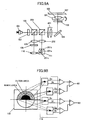
- FIG. 15A is a diagram showing a general configuration of an optical pickup in a twelfth embodiment of the present invention.
- a light source with an operating wavelength of a blue wavelength zone of 407 nm and an object lens of NA: 0.65 are applied for a light-incident side substrate of a thickness of 0.6 mm for a blue-system (large storage capacity) optical recording medium;
- a light source with an operating wavelength of a red wavelength zone of 660 nm and an object lens of NA: 0.65 are applied for a DVD-system optical recording medium having a light-incident side substrate with a thickness of 0.6 mm;
- the wavelength selection aperture 307 has a thin film, as shown in FIG. 15B, which provides no effect on lights of wavelengths of 407 nm and 660 nm, while performs aperture control on a light of a wavelength of 780 nm so that it is focused onto the optical recording medium 107 with NA: 050.
- it is made of a wavelength selection film described for the above-mentioned second embodiment, a transmitting diffraction device, or the like.
- a sufficient luminous energy can be obtained, and, also, a noise occurrence due to the returning light toward the semiconductor laser 101 can also be reduced, as a polarization splitting optical system is formed by a combination of the polarization beam splitter 103 and the 1/4-wavelength plate 308.
- blue/red (DVD system) optical system has the even-th aberration correction device 401 inserted as shown in FIG. 15A according to the twelfth embodiment, it is also possible that also the odd-th aberration correction device is inserted, or, both of the even-th correction device and the odd-th aberration correction device are inserted therein.
- a different point from the twelfth embodiment is that the position is exchanged between the red-system optical system for DVD system and the infrared-system optical system for CD system, as shown in FIG. 16. That is, the blue/infrared (CD system) optical system has the even-th aberration correction device 401 inserted therein.
- the dichroic prism 206 transmits lights of the wavelengths of 407 nm and 780nm, while reflects a light with a wavelength of 660 nm.
- FIG. 17A is a diagram showing a general configuration of an optical pickup in fourteenth embodiment of the present invention.
- a light source with an operating wavelength of a blue wavelength zone of 407 nm and an object lens of NA: 0.85 are provided for a blue-system (large storage capacity) optical recording medium having 0.1 mm in the thickness of a light-incident side substrate thereof;
- a light source with an operating wavelength of a red wavelength zone of 660 nm and an object lens of NA: 0.65 are provided for a DVD-system optical recording medium having 0.6 mm in the thickness of light-incident side substrate thereof;
- a light source with an operating wavelength of an infrared wavelength zone of 780 nm and an object lens of NA: 0.50 are provided for a CD-system optical recording medium having 1.2 mm in the thickness of a light-incident side substrate thereof.
- the optical pickup in this embodiment can perform information recording, reproduction and deletion on each of the above-mentioned three-types of optical recording media.
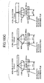
- FIG. 18 is a diagram showing a general configuration of an optical pickup in a fifteenth embodiment of the present invention.
- a light source with an operating wavelength of a blue wavelength zone of 407 nm and an object lens of NA: 0.65 are provided for a the blue-system (large storage capacity) optical recording medium having 0.6 mm in the thickness of a light-incident side substrate thereof;
- a light source with an operating wavelength of a red wavelength zone of 660 nm and an object lens of NA: 0.65 are provided for a DVD-system optical recording medium having 0.6 mm in the thickness of a light-incident side substrate thereof;
- a light source with an operating wavelength of an infrared wavelength zone of 780 nm and an object lens of NA: 0.50 are provided for a CD-system optical recording medium having 1.2 mm in the thickness of a light-incident side substrate thereof.
- This optical pickup can perform information recording, reproduction and deletion on each of these three types of
- a different point from the twelfth embodiment is that the even-th aberration correction device 402 is provided onto a common light path of the three wavelengths of optical systems of blue, red (DVD system) and infrared (CD system), thus, a satisfactory beam spot can be obtained after aberrations are effectively reduced, for each of the three types of optical recording media.
- DVD system blue, red
- CD system infrared
- FIG. 20A is a diagram showing a general configuration of an optical pickup in a seventeenth embodiment of the present invention.
- a light source with an operating wavelength of a blue wavelength zone of 407 nm and an object lens of NA: 0.65 are provided for a blue-system (large storage capacity) optical recording medium having 0 .
- the optical pickup in each of the above-mentioned first through seventeenth embodiments of the present invention may be applied.
- An optical information recording/reproduction apparatus such as that shown in FIG. 21 may perform multi-level recording on an optical recording medium with an information recording density multiplication rate of P1 by applying the usage wavelength of 407 nm ⁇ 10 nm in the blue wavelength zone and NA: 0.6 through 0.7, by applying a multilevel recording technology, where P1 > 1.8.
- an optical information processing apparatus having a recording capacity of 22 GB or more can be realized, without using an object lens of as high as NA: 0.85. That is, generally, the storage capacity to an optical recording medium is determined by the diameter of beam spot applied. In case the blue-system optical recording medium of a blue wavelength zone is used, compared with a DVD-system optical recording medium (4.7 GB), the capacity can be raised by the spot diameter ratio (wavelength/NA) 2 , and thus, 12 GB is achievable. Then, 22 GB is achievable by further applying multi-level recording in the above-mentioned conditions. Consequently, the margin against a possible shift/variation can be increased. Since the depth of focus of an object lens should be managed seriously in proportion to the 2nd power of NA, application of the lens of NA: 0.65 can increase the margin by 1.7 times, compared with the object lens of NA: 0.85.
- an optical information processing apparatus performs multi-level recording with the information recording density multiplication rate P2 on an optical recording medium at an operating wavelength 407 nm ⁇ 10 nm of a blue wavelength zone, with NA: 0.85, where P2 > 1.8.
- a recording capacity of 40 GB or more is realizable in optical information processing apparatus, without using an object lens of as high as NA: more than 0.85.
- a margin can be effectively increased.
- the optical recording medium applicable to the present invention may be of one having a many recording layers collectively, i.e., a multi-layer optical recording medium.
- the storage/recording capacity increases according to the number of layers in this case.
- an optical recording medium having the information recording surface on both sides thereof may also be applied. Thereby, the capacity is able to be doubled.
- a so-called bulk optical system may be applied in which light path splitting is made for red (DVD system) or infrared (CD system) optical system by a polarization beam splitter, etc. with a blue-system optical system configured into a a single unit.
- an optical system which collectively includes 3 systems of a blue system, a DVD system, and a CD system into one unit may also be applied.
- an optical device/part such as a aberration correction device is used in common so that the number of parts/components is effectively reduced, while a satisfactory beam spot can be formed on the information recording surface of each of a blue-system optical recording medium, a DVD-system.optical recording medium, and a CD-system optical recording medium, i.e., in three generations.
- effective correction/reduction in aberration, otherwise occurring at a serious level due to manufacture error or so according to the present invention enables achievement of a high-reliable, size-reduced optical pickup.
- FIG. 22 is a diagram showing a general configuration of an optical pickup in a nineteenth embodiment of the present invention.
- information recording, reproduction or deletion is performed on each of the following two types of optical recording media: one type in which a light source with an operating wavelength of a blue wavelength zone of 407 nm and NA: 0.67 are applied to a light-incident-side. substrate having a thickness of 0.6 mm of a blue-system (large scale) optical recording medium; and the other type in which a light source with an operating wavelength of 660 nm and NA: 0.65 are applied to a light-incident-side substrate having a thickness of 0.6 mm of DVD-system optical recording medium.
- essential parts of this optical pickup includes a blue optical system through which a light in a blue wavelength zone passes including a semiconductor laser 1101 which is a light source of the blue wavelength zone, a collimator lens 1102, a polarization beam splitter 1103, dichroic prisms 1203 and 1303, a deflection prism 1104, a phase correction device 1105, a 1/4-wavelength plate 1106, an object lens 1108, a detection lens 1110, a beam splitting device 1111 and a light-receiving device 1112; and a red optical system for DVD system through which a light in a red wavelength zone passes including a hologram unit 1201, a collimator lens 1202, the dichroic prism 1203, the deflection prism 1104, the phase correction device 1105, the 1/4-wavelength plate 1106, and the object lens 1108. That is, the dichroic prism 1203, the deflection prism 1104, the phase correction device 1105, the 1/4-wavelength plate 1106, and the object lens 1108. That is, the dichroic prism
- the above-mentioned object lens 1108 is designed in a manner such as to form a wavefront having the minimum aberration on the blue-system optical recording medium expecting alight source with an operating wavelength of a blue wavelength zone of 407 nm, NA: 0.67, and having a light-incident-side substrate having a thickness of 0.6 mm.
- a divergent beam in a linear polarization emitted from the semiconductor laser 1101 with wavelength of 407 nm is transformed into an approximately parallels beam by means of the collimator lens 1102, passes through the polarization beam splitter 1103 and the dichroic prism 1203, the light path thereof is deflected 90 degrees by the deflection prism 1104, and it passes through the phase correction device 1105.
- the beam reflected by the optical recording medium 1109 has a circular polarization in the direction opposite to the direction of the same in the above-mentioned going path, and a form of an approximately parallel beam, becomes a linear polarization which intersects perpendicularly with the same in the above-mentioned going path as passing through the 1/4-wavelength plate 1106, is reflected by the polarization beam splitter 1103, is transformed into a convergent beam with the detection lens 1110, undergoes deflection splitting by the beam splitting device 1111 into a plurality of beams, and, thus, is incident onto the light-receiving device 1112. Through the light-receiving device 1112, an aberration signal, an information signal, and a servo signal are detected from the incident beam.
- the hologram unit 1201 integrally includes a chip 1201a of a semiconductor laser, a hologram device 1201b, and a light-receiving device 1201c.
- a 660-nm light which comes out of the semiconductor laser 1201a of this hologram unit 1201 passes through the hologram device 1201b, and is transformed into a parallel beam by the collimator lens 1202.
- the beam is focused as forming a minute spot on the optical recording medium 1109, by which spot information recording, reproduction, or deletion is performed on the optical recording medium 1109.
- the beam reflected by the optical recording medium 1109 is deflected by the deflection prism 1104, is reflected by the dichroic prism 1203, is condensed by the collimator lens 1202 , and, as shown in FIG. 23, the light reflected by the optical recording medium 1109 is diffracted toward the light-receiving device 1201c which is contained in the same can as the semiconductor laser 1201a, by the hologram device 1201b , and is received by light-receiving device 1201c.
- the light-receiving device 1201c an aberration signal, an information signal, and a servo signal are detected from the incident light.
- the configuration of the optical pickup in the nineteenth embodiment is a so-called two-generation-compatible-type optical pickup equipped with the two light sources, i.e., the light of blue wavelength zone and the light of the red wavelength zone for DVD, and achieves this compatibility between the two generations while it does not use an aperture switching device in this case.
- FIG. 24 shows, on an example of an object lens which has the following characteristics:
- a blue optical system of the same aperture is provided with in the wavelength of 407nm NA: 0.67, compared with an optical recording medium of the wavelength of 660 nm for DVD system provided with NA: 0. 65 .
- the recording capacity is proportional to (NA/ ⁇ ) 2 , where ⁇ denotes the wavelength, 2.8 times as large recording capacity can be obtained compared with the DVD-system optical recording medium.
- any one of BaCD12, LaC130, BaF41, NbF1 and so forth may be applied. It is preferable that a glass material for which an aspherical mold formation is allowed. NA with respect to the light of blue wavelength can be controlled also by selection of this glass material.
- FIG. 25 is a diagram showing a general configuration of an optical pickup in a twentieth embodiment of the present invention.
- This embodiment can perform information recording, reproduction or deletion on each of the three types of recording media such as: a first type expecting a light source with an operating wavelength of a blue wavelength zone of 407 nm and NA: 0.65, and having a light-incident-side substrate having a thickness of 0.6 mm in a blue-system optical recording medium; a second type expecting a light source with an operating wavelength of a red wavelength zone of 660nm and NA 0.65, and having a light-incident-side substrate having a thickness of 0.6 mm in a DVD system optical recording medium; and a third type expecting a light source with an operating wavelength of an infrared wavelength zone of 780 nm and NA: 0.50, and having 1.2 mm in thickness of a light-incident-side substrate in a CD-type optical recording medium.
- essential parts of this optical pickup includes a blue optical system through which a light in a blue wavelength zone passes including a semiconductor laser 1101 which is a light source of the blue wavelength zone, a collimator lens 1102, a polarization beam splitter 1103, a dichroic prism 1203, a deflection prism 1104, a phase correction device 1105, a 1/4-wavelength plate 1106, an aperture switching device 1107, an object lens 1108, a detection lens 1110, a beam splitting device 1111 and a light-receiving device 1112; a red optical system for DVD system through which a light in a red wavelength zone passes including a hologram unit 1201, a collimator lens 1202, the dichroic prisms 1203 and 1303, the deflection prism 1104, the phase correction device 1105, the 1/4-wavelength plate 1106, the aperture switching device 1107 and the object lens 1108; and an infrared optical system for CD system through which a light in an infrared wavelength zone passes including a semiconductor laser 1101 which is
- a divergent beam in a linear polarization emitted from the semiconductor laser 1101 with wavelength of 407 nm is transformed into an approximately parallel beam by means of the collimator lens 1102, passes through the polarization beam splitter 1103 and the dichroic prisms 1203 and 1303, the light path thereof is deflected 90 degrees by the deflection prism 1104, and the beam passes through the phase correction device 1105.
- the beam passes through the 1/4-wavelength plate 1106, thus is transformed into a circular polarization, undergoes aperture control by the aperture switching device 1107 into NA: 0.65, and, then, is focused by the object lens 1108 onto the optical recording medium 1109 as a minute beam spot.
- Information recording, reproduction or deletion is performed by this spot on the optical recording medium 1109.
- the beam reflected by the optical recording medium 1109 has a circular polarization in the direction opposite to the direction of the same in the above-mentioned going path, and a form of an approximately parallel beam, becomes a linear polarization which intersects perpendicularly with the same in the above-mentioned going path as passing through the 1/4-wavelength plate 1106, is reflected by the polarization beam splitter 1103, is transformed into a convergent beam with the detection lens 1110, undergoes deflection splitting by the beam division device 1111 into a plurality of beams, and, thus, are incident onto the light-receiving device 1112. Through the light-receiving device 1112, an aberration signal, an information signal, and a servo signal are detected from the incident beam.
- the hologram unit 1201 having the configuration same as that described above for the nineteenth embodiment is used. As shown in FIG. 25, the hologram unit 1201 integrally includes a chip 1201a of a semiconductor laser, a hologram device 1201b, and a light-receiving device 1201c.
- the beam is focused as forming a minute spot on the optical recording medium 1109, by which spot information recording, reproduction, or deletion is performed on the optical recording medium 1109.
- the effective numerical aperture is on the order of 0.65 with respect to the optical recording medium 1109.
- the beam reflected by the optical recording medium 1109 is deflected by the deflection prism 1104, is reflected by the dichroic prism 1203, is condensed by the collimator lens 1202, and, the light reflected by the optical recording medium 1109 is diffracted toward the light-receiving device 1201c which is contained in the same can as the semiconductor laser 1201a, by the hologram device 1201b, and is received by light-receiving device 1201c.
- the light-receiving device 1201c an aberration signal, an information signal, and a servo signal are detected from the incident light.
- a hologram unit 1301 is used for CD system in which light receiving and emitting devices are contained in a single can, and, by using a hologram technology, beam splitting is performed as a common way.
- the hologram unit 1301 integrally includes a semiconductor laser, a hologram device 1301b, and a light-receiving device 1301c.
- the beam reflected by the optical recording medium 1109 is deflected by the deflection prism 1104, is reflected by the dichroic prism 1303, is condensed by the collimator lens 1302, and, the light is then diffracted toward the light-receiving device 1301c which is contained in the same can as the semiconductor laser 1201a, by the hologram device 1301b, and is received by light-receiving device 1301c.
- the light-receiving device 1301c an aberration signal, an information signal, and a servo signal are detected from the incident light.
- FIG. 26 is a diagram showing a general configuration of an optical pickup in a twenty-first embodiment of the present invention.
- information recording, reproduction or deletion is performed on each of the three types of optical recording media expecting a light source with an operating wavelength of a blue wavelength zone of 407 nm and NA: 0.65 in a blue-system optical recording medium with 0.6 mm in thickness of light-incident-side substrate thereof; a light source with an operating wavelength of a red wavelength zone of 660 nm and NA: 0.65 in a DVD-system optical recording medium of 0.6 mm in thickness of light-incident-side substrate thereof; and a light source with an operating wavelength of an infrared wavelength zone of 780 nm and NA: 0.50 in a CD-system optical recording medium of 1.2 mm in thickness of light-incident-side substrate thereof.
- a different point from the configuration of the optical pickup shown in FIG. 25 is a point that a hologram unit 1401 is used in which a blue optical system is contained , i.e., a light source (semiconductor laser 1401a), a light-receiving device 1401c, and a light-path splitting device (hologram 1401b) in a single package.
- a light source semiconductor laser 1401a
- a light-receiving device 1401c i.e., a light-receiving device 1401c
- hologram 1401b light-path splitting device
- FIG. 27 is a diagram showing a general configuration of an optical pickup in a twenty-second embodiment of the present invention.
- information recording, reproduction or deletion is performed on each of the three types of optical recording media.
- the first type is such that a light source with an operating wavelength of a blue wavelength zone of 407 nm and NA 0.65 are expected, i.e., a blue-system optical recording medium of 0.6 mm in thickness of light-incident-side substrate.
- the second type is such that a light source with an operating wavelength of a red wavelength zone of 660 nm and NA 0.65 are expected, i.e., a DVD-system optical recording medium of 0.6 mm in thickness of light-incident-side substrate.
- the third type is a CD-system optical recording medium expecting a light source with an operating wavelength of an infrared wavelength zone of 780 nm and NA: 0.50, and having 1.2 mm in thickness of light-incident-side substrate.
- a different point from the configuration of the optical pickup shown in FIG. 26 is a point in which light sources (semiconductor lasers 1201a and 1301a) , light-receiving devices 1201c and 1301c, and a light-path splitting device (hologram 1501b) are collectively provided in a single package as a hologram unit 1501.
- a configuration including both a layer for DVD and a layer for CD should be used as the hologram device 1501b as shown in FIG. 28.
- FIG. 29A shows a relationship between the effective diameters needed for achieving NA: 0.65 and the wavelength applied in the following conditions:
- a wavelength selection diffraction grating 1121 may be used, which has a function of diffracting an incident beam according to the wavelength thereof selectively, thereby, defining the diameter of a beam which can be transmitted thereby.
- switching of beam diameter according to the wavelength of an incident beam can be achieved.
- each pickup can perform information recording, reproduction or deletion on each of the three types of optical recording media, i.e., in the first type, a light source with an operating wavelength of a blue wavelength zone of 407 nm and NA 0.67 are substantially provided for a blue-system optical recording medium with 0.6 mm in thickness of a light-incident-side substrate thereof; in the second type, a light source with an operating wavelength of a red wavelength zone of 660 nm and NA 0.65 are substantially provided for a DVD-system optical recording medium with 0.6 mm in thickness of a light-incident-side substrate thereof; and in the third type, a light source with an operating wavelength of an infrared wavelength zone of 780 nm and NA 0.50 are substantially provided for a CD-system optical recording medium with 1.2 mm in thickness of
- the object lens 1108 is designed in a manner such that the aberration becomes minimum for a blue-system optical recording medium having 0.6 mm in thickness of a light-incident-side substrate for which a light source of operating wavelength of 407 nm (blue wavelength zone) and NA: 0.67 are substantially provided.
- a divergent beam in a linear polarization emitted from the semiconductor laser 1101 with wavelength of 407 nm is transformed into an approximately parallel beam by means of the collimator lens 1102, passes through the polarization beam splitter 1103 and the dichroic prisms 1203 and 1303, the light path thereof is deflected 90 degrees by the deflection prism 1104, and the beam passes through the phase correction device 1105.
- the beam passes through the 1/4-wavelength plate 1106, thus is transformed into a circular polarization, is subject to no effect by the aperture switching device 1107, and, then, is focused by the object lens 1108 onto the optical recording medium 1109 as a minute beam spot.
- Information recording, reproduction or deletion is performed by this spot on the optical recording medium 1109.
- the beam reflected by the optical recording medium 1109 reaches the light-receiving device 1112 as in the twentieth embodiment described above, and, thereby, respective signals are detected.
- the beam is focused as forming a minute spot on the optical-recording medium 1109, by which spot information recording, reproduction, or deletion is performed on the optical recording medium 1109.
- the effective numeral aperture is on the order of 0.65 with respect to the optical recording medium 1109.
- the beam reflected by the optical recording medium 1109 reaches the light-receiving device 1112, and, thereby, respective signals are detected.
- the optical pickup is of three-generation compatible optical pickup including the three-types of light sources for blue, red and infrared wavelength zones, not a three-step aperture switching device but a two-step aperture switching device which is conventionally applied is applied
- FIG. 34 shows, in case of applying the object lens same as in the case of FIG. 24, a range of effective diameter (incident beam diameter) ⁇ 3 providing NA: 0.44 through 0.51 when a beam of infrared wavelength of 780 nm is incident onto an optical recording medium having the substrate thickness of 1.2 mm. From this figure, it is seen that the effective diameter (incident beam diameter) ⁇ 3 should fall within the range between 2.78 and 3.18 mm for the object lens having NA: 0.65.
- the aperture switching device 1107 which switches the transmitting beam diameter
- optical characteristic of reflection, diffraction, or absorption may be utilized and, thus, according to the wavelength zone or the polarization direction of an incident optical beam, the transmission beam diameter is controlled.
- FIGS. 35A through 35C illustrate states in which a beam of the blue wavelength zone, a beam of the red wavelength zone, and a beam of the infrared wavelength zone are applied to the aperture switching device.
- a dielectric optical multilayer film which has a wavelength selection property is used in that a wavelength selection property reflective film 1120' which switches a beam diameter to allow a passage therethrough by controlling a reflection according to the wavelength of each beam which is incident thereon from the light source.
- FIGS. 36A through 36C illustrate states in which a beam of the blue wavelength zone, a beam of the red wavelength zone, and a beam of the infrared wavelength zone are applied to another example of the aperture switching device.
- a wavelength switching diffraction grating 1121' which has a wavelength selection property is used which switches a beam diameter to allow a passage therethrough by controlling a diffraction according to the wavelength of each beam which is incident thereon from the light source.
- the incident beam has no effected applied thereby for each of lights of the blue wavelength zone, the red wavelength zone, and the infrared wavelength zone within a beam diameter ⁇ 3, a central area in which no diffraction grating is provided.
- a wavelength selection absorption film 1122' shown in FIGS. 37A through 37C may be instead applied which switches an transmitting beam diameter by selectively absorbing an incident light according to the wavelength of thereof.
- switching of beam diameter may be achieved by another method employing a polarization property. That is, a light source may be arranged so that the polarization direction of the light of a red wavelength zone and an infrared wavelength zone may intersect perpendicularly, and then, a device may be provided by which, according to the polarization direction of a beam incident, the aperture is switched.
- a spherical aberration occurs due to a difference in the thickness of the light-side substrate of the optical recording medium, as shown in FIG. 38 or 39.
- a phase correction device to generate a spherical aberration in the opposite polarity is applied.
- a finite system may be instead applied by which a beam incident onto the object lens is made divergent or convergent as a red (DVD) optical system or an infrared (CD) optical system.
- a beam incident onto the object lens is made divergent or convergent as a red (DVD) optical system or an infrared (CD) optical system.
- the divergence in a beam incident onto the object lens is changed, and, thus, equivalently, generally, the spherical aberration can be controlled. Accordingly, thus, a spherical aberration in the opposite polarity can be provided thereby.
- FIG. 40A a case is assumed in that a spherical aberration generated when a light in the infrared wavelength zone is incident onto a CD-system optical recording medium with an infinite system is such as that shown in FIG. 40A.
- FIG. 40B shows this spherical aberration as a 2-dimensional curve.
- a spherical aberration as shown in FIG. 40C is obtained as a spherical aberration after the correction.
- any of a static device and a dynamic device may be applied as long as it adds a predetermined amount of phase to an incident light according to each type of optical recording medium on which information recording, reproduction or deletion is performed. Then, the predetermined phase to be added may be controlled according to an output signal of a medium identification device for optical recording media, which will be described later, a spherical aberration detection device, or a substrate thickness detection device, in a case where a dynamic device is provided for the purpose.
- an electro-optic device such as a liquid crystal device may be employed as a dynamic phase correction device.
- a liquid crystal device can change the refractive index 'n' of the liquid crystal at each electrode division free in a range between n1 and n2, as a transparent electrode at least one side is divided in a shape of concentric circles, to which applied is a voltage independently for each electrode division (with respect to a common electrode) of each concentric circular zone, and controls the above-mentioned voltage.
- an arbitrary phase difference ⁇ n ⁇ d (2 ⁇ / ⁇ ) can be given to an incident light which passes through each zone, as a result of a light path difference ⁇ n ⁇ d ( ⁇ n denoting a difference in the refractive index, and d denoting the cell thickness of liquid crystal) being controlled, where the wavelength is denoted as ⁇ .
- FIG. 40A A solid curve shown in FIG. 42A shows this spherical aberration as a 2-dimensional curve.
- a voltage applied to each concentric circular electrode of the liquid crystal device is adjusted so that a phase difference as shown by a broken curve shown in FIG. 42B be given to a beam which is incident onto an object lens from a light source side, the spherical aberration can be cancelled out thanks to a delay of the wavefront created in each concentric cross-sectional part of the beam which passes through the liquid crystal device.
- FIG. 42C shows the sum total of the solid curve (spherical aberration) in FIG. 42B, and the broken curve (delay of the wavefront cause by the liquid crystal device), i.e., the spherical aberration after correction.
- the spherical aberration can be remarkably corrected or reduced.
- such a phase correction device can also correct or effectively reduce a spherical aberration resulting from a layer gap in a double-layer optical recording medium, or a substrate thickness error of a blue-system optical recording medium, or the like, at the same time.
- an output signal of a medium identification device may be used as a control signal for this type of dynamic phase correction device.
- a beam from a light source of this device is applied to an object lens at a time of information recording or reproduction of DVD or CD as above-mentioned, a spherical aberration caused by a difference in wavelength or substrate thickness occurs, and the shape of the optical spot formed on a recording surface deteriorates.
- By detecting this state in the optical spot it is possible to identify which type of optical recording medium is currently applied.
- a spherical aberration amount of opposite polarity for canceling out a spherical aberration to generate is stored beforehand for every type of optical recording medium, and, the spherical aberration of opposite polarity is provided according to the type of optical recording medium detected by means of the above-mentioned medium identification device.
- the medium identification device should have a configuration such that the reflected beam's luminous energy level obtained when blue, red, or infrared light source is turned on, and a focus search is carried out as an optical recording medium is loaded is used for the medium identification.
- an output signal of a spherical aberration detection device may be used.
- a beam from a light source of this device is applied to an object lens with an infinite system, at a time of information recording or reproduction of DVD or CD, a spherical aberration caused by difference in wavelength or substrate thickness occurs, and the shape of optical spot formed on a recording surface deteriorates.
- the aberration thus occurring also distorts the wavefront of a beam reflected, and thus, an aberration occurs in a beam returning to the light-receiving device 1201c via the collimator lens 1202 shown in FIG. 25, for example.
- FIG. 43A shows this state.
- a spherical aberration occurs in the returning, beam, with respect to a standard wavefront of the returning beam, a delay in wavefront occurs concentrically about the optical axis, and a position at which the wavefront delayed with respect to the focus point at which the standard wavefront focuses is in a defocus state. Then, the state of spherical aberration can be seen by taking out the difference of the delayed wavefront and the standard wavefront, and thus, the focus state can be detected.
- a light-receiving device 1201c is provided in which a light-receiving area is divided, while a concentric division pattern of a hologram 1201b is provided, whereby each concentric cross-sectional zone of an incident beam can be detected.
- the hologram 1201b has a configuration such that symmetrical dividing in the jitter direction on the plane perpendicular to the optical axis is made, and, one division is further divided concentrically, and, thus, a hologram is formed.
- a light-receiving device 1130 includes 2-divided light-receiving devices which detect beams diffracted by the hologram, as shown.
- a substrate thickness detection device and a device for determining a difference between a blue-system optical recording medium and the other types of optical recording medium This enables a check of difference between a blue-system optical recording medium and a CD-system system optical recording medium or a difference between a DVD-system optical recording medium, and a CD-system optical recording medium.
- a method of detecting the thickness (light-incident-side substrate thickness) of an optical transmission layer of an optical recording medium as in the substrate thickness detection device a method may be applied in which a beam from a light source is applied to an optical recording medium via an object lens, the reflected beam is detected by a light-receiving device, by which a focus error signal is obtained, while, by using this focus error detection system, a signal according to a light reflected by a recording surface of the optical recording medium and a signal according to a light reflected by an optical transmission layer of the same optical recording medium are extracted, and, therefrom, a time difference therebetween is detected, and, thus, the substrate thickness (thickness of the optical transmission layer) is detected.
- this method since a manufacture error in the optical recording medium is also detectable, it becomes possible to correct or effectively reduce the spherical aberration occurring in connection with the manufacture error together at a same time.
- the above-described dynamic phase correction device may have a function of also performing a phase correction other than correcting a spherical aberration.
- a beam spot degradation caused by a tilt in an optical recording medium may be corrected through a function of correcting or effectively reducing a coma aberration occurring due to a relative inclination between the optical recording medium and object lens.
- the 1/4 wavelength plate 1106 is provided such that, thereby, while a light (blue system) with a wavelength of 407 nm and a light (DVD system) with a wavelength of 660 nm are transformed into a linear polarization from a circular polarization, or from a linear polarization to a circular polarization; for a light (CD system) with a wavelength of 780 nm, transformation into a circular polarization or an ellipse polarization from a linear polarization is performed.
- a crystal having a thickness 't', a phase difference between the ordinary light (refractive index: no) and extraordinary light (refractive index: new) be 1/4 of the wavelength of 407 nm, or the wavelength of 660 nm.
- a polarization separation optical system is achieved by a combination of the polarization beam splitter 1103 and the 1/4-wavelength plate 1106 for a blue-system optical recording medium, thus, a sufficient luminous energy is obtained, and, also, a noise occurring due to a returning light directed to the semiconductor laser 1101 is also effectively reduced.
- such a polarization separation optical system may also be achieved for a DVD-system optical recording medium by using the hologram device of polarization selection property with the hologram 1201b shown in FIG. 22.
- the above-mentioned phase correction device 1105, the 1/4-wavelength plate 1106, and the aperture switching device 1107 may be provided on an actuator together with the object lens, and, may be. moved integrally. Thereby, a wavefront degradation caused by a relative shift and relative tilt among these components/parts can be effectively reduced compared with the case where these components/parts are provided separately.
- the actuator according to the embodiment of the present invention may be have any of two through four axes of moving dimensions. In other words, in addition to two-directional control for focus and tracking control operations, one-directional tilt control for the radial direction or the jitter direction, and, thus, total three-axis actuator may be provided.
- a high-S/N multi-generation-compatible optical pickup can be achieved with a reduced weight, a reduced cost, and simplified design and manufacture processes. Further, by employing a blue wavelength zone in a light source, and multi-level recording technology, increase in recording capacity more than 22 GB is feasible in an optical information process apparatus.
- FIG. 45 illustrates an optical pickup in the twenty-fifth embodiment of the present invention for performing information recording, reproduction or deletion on an optical recording medium with an operating wavelength of 407 nm, NA: 0.65 and 0.6 mm in thickness of light-incident side substrate.
- Essential parts/components of this optical pickup include a semiconductor laser 2101 of a blue wavelength zone, a collimator lens 2102, a polarization beam splitter 2103, a deflection prism 2104, a phase correction device 2105, a 1/4-wavelength plate 2106, an object lens 2108, a detection lens 2110, a beam splitting device 2111, and a light-receiving device 2112, as shown.
- the light reflected by the optical recording medium 2109 has a circular polarization in the direction opposite to the above-mentioned case of coming toward the optical recording medium 2109 and of an approximately parallel beam, becomes a linear polarization perpendicular to the above-mentioned case of coming toward the optical recording medium by passing through the 1/4-wavelength plate 2106, and is reflected by the polarization beam splitter 2103. Then, the beam is focused by the condenser 2110, is deflected in a splitting manner by the beam splitting device 2111 into a plurality of beams, which are then incident on the light-receiving device 2112. From the light-receiving device 2112, an aberration signal, an information signal, and a servo signal are detected.
- FIG. 46 shows an outline configuration of an optical pickup in the twenty-sixth embodiment of the present invention. This embodiment is the same as the above-described twenty-fifth embodiment except that, instead of the phase correction device 2105, an expander 2113 is used.
- FIG. 47 shows an optical pickup according to the twenty-seventh embodiment of the present invention for performing information recording, reproduction or deletion on a blue-system optical recording medium with an operating wavelength of 407 nm and NA: 0.65, having an light-incident side substrate with a thickness of 0.6 mm, and, also, a DVD-system optical recording medium with an operating wavelength of 660 nm and NA: 0.65, having a light-incident side substrate with a thickness of 0.6 mm.
- This embodiment is provided with, as shown in FIG.
- a semiconductor laser 2101 of a blue wavelength zone a collimator lens 2102, a polarization beam splitter 2103, a dichroic prism 2203, a deflection prism 2104, a phase correction device 2105, a 1/4-wavelength plate 2106, an aperture switching device 2107, an object lens 2108, a detection lens 2110, a beam splitting device 2111 and a light-receiving devices 2112, which form a blue optical system provided for a light of the blue wavelength zone.
- the embodiment also includes a DVD-system optical system provided for a light of a red wavelength zone which includes a hologram unit 2201, a collimator lens 2202, the dichroic prism 2203, the deflection prism 2104, the phase correction device 2105, the 1/4-wavelength plate 2106, and the object lens 2108. That is, the dichroic prism 2203, the deflection prism 2104, the phase correction device 2105, the 1/4-wavelength plate 2106, and the object lens 2108 are the common parts between the two optical systems. Furthermore, the object lens 2108 is designed so that the optimum wavefront best be provided for the blue-system optical recording medium with the operating wavelength of 407 nm and NA 0.65 having 0.6 mm in thickness of the light-incident side substrate thickness.
- the beam is deflected in its light path 90 degrees by the deflection prism 2104, passes through the phase correction device 2105, passes through the 1/4-wavelength plate 2106 by which the light is transformed into a circular polarization. After that, the beam passes through the aperture switching device 2107, then, is incident onto the object lens 2108, and, thus, is focused into a minute beam spot on the optical recording medium 2109. Informational recording, reproduction, or deletion is performed by this spot onto the optical recording medium 2109.
- the hologram unit 2201 includes integrally a chip 2201a of a semiconductor laser, a hologram device 2201b, and a light-receiving device 2201c.
- the beam reflected by the optical recording medium 2109 is deflected by the deflection prism 2104, is reflected by the dichroic prism 2203, is condensed by the collimator lens 2202, and, as shown in FIG. 48, the light reflected by the optical recording medium 2109 is diffracted towards the light-receiving device 2201c which is contained in the same can as the semiconductor laser 2201a, by the hologram device 2201b, and is received by the light-receiving device 2201c.
- the light-receiving device 2201c an aberration signal, an information signal, and a servo signal are detected from the incident light.
- FIG. 49 illustrates an optical pickup according to the twenty-eighth embodiment of the present invention for performing information recording, reproduction or deletion onto a blue-system optical recording medium with an operating wavelength of 407 nm and NA: 0.65, having 0.6 mm in thickness of a light-incident side substrate thereof, a DVD-system optical recording medium with an operating wavelength of 660 nm and NA: 0.65, having 0.6 mm in thickness of a light-incident side substrate, and a CD-system optical recording medium with an operating wavelength of 780 nm and NA 0.50, having 1.2 mm in thickness of a light-incident side substrate.
- This optical pickup has a blue-system optical system provided for a light in the blue wavelength zone, which includes a semiconductor laser 2101 of the blue wavelength zone, a collimator lens 2102, a polarization beam splitter 2103, dichroic prisms 2203 and 2303, a deflection prism 2104, a phase correction device 2105, a 1/4-wavelength plate 2106, an aperture switching device 2107, an object lens 2108, a detection lens 2110, a beam splitting device 2111 and a. light-receiving device 2112.
- a blue-system optical system provided for a light in the blue wavelength zone, which includes a semiconductor laser 2101 of the blue wavelength zone, a collimator lens 2102, a polarization beam splitter 2103, dichroic prisms 2203 and 2303, a deflection prism 2104, a phase correction device 2105, a 1/4-wavelength plate 2106, an aperture switching device 2107, an object lens 2108, a detection lens 2110, a beam splitting
- the dichroic prism 2203, 2303, the deflection prism 2104, the phase correction device 2105, the 1/4-wavelength plate 2106, the aperture switching device 2107, and object lens 2108 are the common parts between two of or three optical systems.
- the object lens 2108 is designed so that the optimum wavefront be provided for the blue-system optical recording medium with the operating wavelength of 407 nm and NA: 0.65, having 0.6 mm in thickness of the light-incident side substrate thickness.
- the light After being reflected by the optical recording medium 2109, the light has a circular polarization in the direction opposite to that in the above-mentioned case of coming into the optical recording medium, is transformed into an approximately parallel beam again, is transformed into a linear polarization perpendicular to that in the above-mentioned case of coming into the optical recording medium by the 1/4-wavelength plate 2106, and is reflected by the polarization beam splitter 2103, is transformed into a convergence light with the condenser 2110, is deflected in a splitting manner by the beam splitting device 2111 into a plurality of beams, which are then incident on the light-receiving device 2112. From the light-receiving device 2112, a aberration signal, an information signal, and a servo signal are detected.
- the 660-nm light which comes out of the semiconductor laser 2201a of this hologram unit 2201 passes through the hologram 2201b and thus, it is transformed into a parallel beam by the collimator lens 2202. Then, this beam is reflected by the dichroic prism 2203 which transmits a light in the blue wavelength zone while reflects a light in the red wavelength zone for DVD, in the direction toward the deflection prism 2104.
- the deflection prism 2104 By the deflection prism 2104, the light path is deflected 90 degrees, and then, a predetermined phase is added thereto by the phase correction device 2105.
- the 1/4-wavelength plate 2106 then transforms the beam into a circular polarization, and with the aperture switching device 2107, no effect is provided at all, the beam then is incident onto the object lens 2108, by which the beam is focused into a minute spot on the optical recording medium 2109. Informational recording, reproduction, or deletion is performed by this spot on the optical recording medium.
- the beam After being reflected by the optical recording medium 2109, the beam is deflected by the deflection prism 2104, is reflected by the dichroic prism 2203, is made into a convergence light by the collimator lens 2202, is diffracted by the hologram 2201b in the direction toward the light-receiving device 2201c which is held in the same can as the semiconductor laser 2201a, and, as shown in FIG. 48, is received by light-receiving device 2201c. From the light-receiving device 2201c, a aberration signal, an information signal, and a servo signal are detected.
- the 1/4-wavelength plate 2106 transforms the light into an ellipse polarization or a circular polarization, and the light is controlled in its cross section into NA: 0.50 with the aperture switching device 2107. After that, the light is incident onto the object lens 2108, and thereby, it is focused into a minute spot on the optical recording medium 2109. Informational recording, reproduction, or deletion is performed by this spot onto the optical recording medium 2109.
- X denotes the coordinate along the optical axis direction
- Y denotes the coordinate along the direction perpendicular to the optical axis
- R denotes the paraxial curvature radius
- K denotes the cone constant
- A, B, C, D, E, F, ... denote high-order coefficients.
- S1 denotes the surface of the object lens 2108 directed to the light source
- S2 denotes a surface on which the two lenses are stuck together
- S3 denotes the surface of the object lens 2108 directed toward the optical recording medium.
- the lens thickness which is the separation between the surface S1 and S3 is 2.193247 mm, and, the thickness of 1.438349 mm of the surface S3 denotes the working distance.
- S4 denotes the light-incident side surface of the light-incident side substrate 2109a
- IMG denotes the recording surface Sr of the optical recording medium.
- the first surface S1 be an aspherical surface
- the third surface S3 be any of an aspherical surface, spherical surface or flat surface
- the intermediate sticking surface be a spherical surface
- a single object lens 2108' shown in FIG. 51A for a comparison purpose has the following characteristics, a change in the aberration according to the operating wavelength shifted from 407 nm of the central wavelength is shown in FIGS. 51B and 51C.
- Incidence beam diameter 3.9 mm; Type of glass: BaCD5 (made by Hoya Corp.); Thickness of substrate in the optical recording-medium: 0.6 mm
- FIG. 51B shows the wavefront aberration where the focus servo operation is performed so that best focus state is obtained for each wavelength while FIG. 51C shows the wavefront aberration where the focus servo operation is fixed at a position at which the best focus state is obtained for the wavelength of 407 nm. That is, from FIG. 51B, a state of increase in the wavefront aberration can be seen for 1 ⁇ a variation in light-source beam emission wavelength due to a particular product or 2 ⁇ a fluctuation of the same according to the temperature change which (the order of milliseconds) the focus servo control can follow up. On the other hand, from FIG.
- a sate of increase in the wavefront aberration can be seen for 3 ⁇ a change in light-source beam emission wavelength according to output shift of the same at a time of information recording/reproduction, or 4 ⁇ a change of the same according to wavelength distribution in multi-mode light emission which the focus servo control can not follow up, as mentioned' above.
- the order of ⁇ 10 nm should be anticipated.
- the order of ⁇ 1 nm should be anticipated.
- the single object lens 2108' shown in FIG. 51A does not satisfy the second requirement as shown in FIG. 51C. Accordingly, in this case, the beam spot may not be well focused on the optical recording medium, and, thus, signal recording/reproduction error/degradation may occur. Accordingly, some special device which can effectively reduce the aberration is needed for putting this machine into a practical use.
- FIG. 52 shows a situation of wavefront aberration which increase according to a wavelength change. As shown in the figure, this has an even-th shape symmetrical with respect to the optical axis.
- a specific device for effectively reducing such a symmetrical aberration with respect to the optical axis will now be described. Two types of devices for this purpose can be considered. One thereof is to provide a concentric circular phase shift to a beam to be incident onto the object lens. The other one is to control the divergence state of the object lens incidence light.
- To give a concentric circular phase shift to a beam means to give a concentric circular shift in delay on a wavefront of the beam. Accordingly, the desired effect can be achieved by providing an aberration which has the magnitude same as but has the opposite polarity to the aberration which the entire optical system originally has. For example, it is assumed that the aberration occurring is as shown in FIG. 52.
- the solid curve shows line shown in FIG. 53A shows the same wavefront aberration expressed as a 2-dimensional curve.
- FIG. 53A is provided to a beam which is incident onto the object lens from the end of light source, the aberration can be cancelled out by the delay of the wavefront of the beam to which the phase shift is thus provided.
- FIG. 53B shows the sum of the solid curve (wavefront aberration) shown in FIG. 53A, and the broken curve (delay of the wavefront provided by the intentionally provided phase shift). Accordingly, by providing a correction device which can provide the phase shift as shown by the broken curve shown in FIG. 53A, the aberration can be well corrected or effectively reduced as shown in FIG. 53B.
- FIG. 54A shows the same wavefront aberration as a 2-dimensional curve.
- FIG. 55 shows a change in wavefront aberration with respect to a wavelength change in case the focus servo is fixed at the best focus position on the central wavelength of 407 nm.
- the broken-line curve shows the change in wavefront aberration in the same conditions on the case of the single object lens 2108' (see FIG. 51A) shown in FIG. 51C, while the solid-line curve shows the wavefront aberration in the same condition on the case of the combined stuck object lens 2108 in each of the above-mentioned twenty-fifth through twenty-eighth embodiments.
- the wavefront aberration falls within 0.07 ⁇ even when the wavelength changes on the order of ⁇ 1 nm. Accordingly, the chromatic aberration is satisfactorily controlled in the case of two stuck combined lens 2108 according to the present invention.
- the weight of the combined stuck object lens 2108 shown in FIG. 50 is approximately 85 mg, and thus, it is lighter than that in the art disclosed in the above-mentioned Japanese laid-open patent application No. 2001-13406.
- an aberration correction is achieved by utilizing a separate device such as a phase correction device described later for a wavelength variation or wavelength fluctuation which the focus servo control can follow up. Thereby, a sufficient performance can be ensured even when the thickness of the object lens is reduced.
- the chromatic aberration can be sufficiently corrected or reduced by such a type of combined stuck object lens.
- the chromatic aberration caused by wavelength change which the focus servo control by an actuator cannot follow can be well corrected or reduced.
- the chromatic aberration caused by this type of wavelength variation/fluctuation can be well controlled by means of the phase correction device 2105 or expander 2113 described above.
- Such a type of correction device can perform a sufficient chromatic aberration control function as a result controlling its phase shift or its moving amount according to an output signal provided by a predetermined wavefront aberration detection device.
- the distance between respective recording layers also causes a wavefront aberration.
- 30-micrometer order is assumed, and, thus, a control of the wavefront aberration is demanded.
- the phase correction device 2105 in each of the twenty-fifth through twenty-eighth embodiments of the present invention may also be used for correcting or effectively reducing the wavefront aberration occurring due to the substrate thickness error of a blue-system optical recording medium, interlayer distance (spacer thickness) of a multilayer optical recording medium, and so forth, together.
- the wavefront aberration (sectional view) when a light with a wavelength of 417 nm is applied onto the object lens 2108 designed for a central wavelength of 407 nm shown in FIG. 50 is shown in FIG. 58.
- the wavefront aberration (sectional view) when the thickness of the optical recording medium applied shifts 0.03 mm with the same object lens 2108 becomes as shown in FIG. 59.
- each aberration has an even-th shape symmetrical with respect to the optical axis. Accordingly, it can be well controlled by applying the above-mentioned phase correction device 2105.
- an output signal of a wavefront aberration detection device may be used as a control signal for the phase correction device 2105.
- a chromatic aberration occurs due to occurrence of wavefront variation or wavelength fluctuation, and, thereby, a shape of a beam spot formed on the recording surface of an optical recording medium applied is distorted.
- the wavefront of a beam reflected by the recording surface is distorted, and thus, an aberration occurs in the beam returning to the light-receiving device 2112 via the detection lens 2110 shown in FIG. 45.
- FIG. 61 shows this state.
- a light-receiving device 2112 is provided in which a light-receivingarea is divided, while a concentric division pattern of a hologram 2111 is provided, whereby each concentric cross-sectional zone of an incident beam can be detected.
- the hologram 2111 has a configuration such that symmetrical dividing in the jitter direction (of an optical recording medium loaded) on the plane perpendicular to the optical axis is made, and, one division is further divided concentrically, and, thus, a hologram is formed.
- a light-receiving device 2112 includes 2-divided light-receiving devices which detect beams diffracted by the hologram, as shown.
- the above-mentioned aperture switching device 2107 shown in FIGS. 47 and 49 which switches a beam applied to the object lens will now be described.
- the above-described optical pickup according to the twenty-seventh embodiment of the present invention is a so-called two-generation compatibility type optical pickup including the two light sources for a light of blue wavelength zone and a light of red wavelength zone for DVD.
- the above-described optical pickup according to the twenty-eighth embodiment of the present invention is a three-generation compatibility type optical pickup including the three light sources for a light of blue wavelength zone, a light of red wavelength zone for DVD, and a light of infrared wavelength zone for CD.
- the NA applied differs according to the generation.
- the NA for a CD-system optical recording medium is set in the range of 0.45 through 0.55, the operating wavelength of 780 ⁇ 20 nm is used, and 1.2 ⁇ 0.03 mm in substrate thickness is applied.
- the NA for a DVD-system optical recording medium is set in the range of 0.59 through 0.66, 0.6 ⁇ 0.03 mm in the substrate thickness is applied, and the operating wavelength of 660 ⁇ 20 nm is used.
- NA of 0.65 through 0.85 may be applied.
- the optical transmission characteristic is such that the central area within ⁇ 3 in which no diffraction lattice is provided transmits a light of blue wavelength zone, red wavelength zone, and infrared wavelength zone; the next peripheral area in the range of ⁇ 3 through ⁇ 2 (area from the perimeter of ⁇ 3 toward ⁇ 2) has no effect on a light of blue wavelength zone and red wavelength zone, but diffracts only a light of infrared wavelength zone; and the further peripheral area in the range of ⁇ 2 through ⁇ 1 (area from the perimeter of ⁇ 2 toward ⁇ 1) has no effect on a light of blue wavelength zone but diffracts a light of red wavelength zone and infrared wavelength zone.
- a device which switches a beam diameter thanks to an absorption according to the wavelength of a beam which comes out of the light source may be used as the aperture switching device 2107 as shown in FIG. 65A through 65C.
- any other device may be instead applied which utilizes a polarization characteristic, for example. That is, the light sources may be arranged so that the polarization direction of the light of red wavelength zone and infrared wavelength zone may intersect perpendicularly, and according to this polarization direction that intersects perpendicularly, the aperture may be switched.
- the phase correction device 2105, the 1/4-wavelength plate 2106, and the aperture switching device 2107 may be combined integrally. Thereby, simplification of assembly process can be attained.
- one of the glass substrates which sandwich the liquid crystal layer which forms the phase correction device 2105 is formed as the 1/4-wavelength plate 2106, while the aperture switching device 2107 is formed by a dielectric multilayer film formed on a side of the other glass substrate opposite to the liquid crystal layer.
- the above-mentioned phase correction device 2105, the 1/4-wavelength plate 2106, and the aperture switching device 2107 may be provided on an actuator together with the object lens, and, thus may be moved integrally. Thereby, a wavefront degradation caused by a relative shift and relative tilt among these components/parts can be effectively reduced compared with the case where these components/parts are provided separately.
- the actuator according to the embodiment of the present invention may be of any of two through four axes of moving dimensions. In other words, in addition to two-directional control for focus and tracking control operations, one-directional tilt control for the radial direction or the jitter direction, and, thus, total three-axis actuator may be provided.
- FIG. 21 is an internal perspective view showing a general configuration of an information recording/reproduction apparatus according to the eighteenth embodiment of the present invention described above. The same figure is also used for illustrating a twenty-fourth embodiment of the present invention.
- the information recording/reproducing apparatus 10, according to the twenty-fourth embodiment also performs at least one of informational recording, reproduction, and deletion with an optical pickup 11 onto an optical recording medium 20.
- the optical recording medium 20 is disk-like, and is contained in a cartridge 21 as a protection case.
- the optical pickup in each of the above-mentioned twenty-fifth through twenty-eighth embodiments of the present invention may be applied.
- the first chromatic aberration correction device for controlling a wavefront aberration occurring due to a change in wavelength which the focus servo control cannot follow up, i.e., a change in wavelength caused by a change in light-emission intensity occurring at a time of optical information recording/reproduction, or a change in wavelength caused by a wavelength distribution provided for the multi-mode light emission; and also, the second chromatic aberration correction device for controlling a wavefront aberration occurring due to a change in wavelength which the focus servo control can follow up, i.e., a variation in central wavelength of the light source due to a particular product lot or the same occurring due to a temperature change.
- the above-mentioned second chromatic aberration correction device may be used in common as an aberration correction device for substrate thickness error of optical recording medium, an aberration correction device for a distance between a plurality of information recording surfaces of a multilayer optical recording medium, an aberration correction device for enabling proper compatibility between different-generation optical recording media having different operation wavelengths and different substrate thicknesses. Accordingly, it is possible to provide an optical pickup in which chromatic aberrations and so forth can be well controlled, without considerably increasing the number of components/parts.
- Optical design for compatible lens between DVD and the next generation video disk system M. Itonaga: J. Magn. Soc. Japan, Vol.25, No. 3-2, 201 discloses a compatibility type optical pickup for a blue-system optical recording medium and DVD-system optical recording medium. This has two semiconductor lasers having different wavelengths and a phase correction device having a hologram pattern formed therein. Information recording and reproduction are performed with a beam coming from one semiconductor laser onto a blue-system optical recording medium with a thickness of 0.1 mm using a light with a wavelength of 405 nm.
- information recording and reproduction is performed with a beam coming from the other semiconductor laser onto a DVD-system optical recording medium with a thickness of 0.6 mm using a light with a wavelength of 650 nm.
- the phase distribution is not changed for the light with the wavelength of 405 nm, while the phase distribution is changed for the light with the wavelength of 660 nm by the phase correction device.
- a spherical aberration occurring due to the difference in the substrate thickness can be effectively reduced.
- the above-mentioned phase correction device which is a wavelength selection phase plate has a phase distribution not changed for a light with the wavelength of 405 nm, while has a phase distribution changed for a light of the wavelengths of 660 nm and 780 nm.
- two types of measures are taken for the purpose of controlling the spherical aberration caused due to the difference in the substrate thickness of optical recording medium, one of which is to apply the wavelength-selection phase correction device, and the other of which is to apply the finite system on DVD/CD.
- Marechal's criterion 0.07 ⁇ rms may be used.
- an optical pickup there may occur various error factors, i.e., a thickness error of optical recording medium, a tilt error of optical recording medium, a defocus error occurring due to a positional error between the object lens and optical recording medium, and so forth.
- finite systems are applied for the DVD-system light path and CD system light path.
- the spherical aberration may increase accordingly with a tracking operation of the object lens.
- Another aspect of the present invention is directed to solve the above-described problems, and, thus, another object of the present invention is especially to well control the residual spherical aberration into less than 0.030 ⁇ rms at the design median in a configuration of an optical pickup in which the above-mentioned three-types of optical recording systems, i.e., blue system, DVD system and CD system can be handled with a single common object lens.
- FIG. 68 shows a general configuration of an optical pickup according to a twenty-ninth embodiment of the present invention.
- information recording, reproduction or deletion is performed on each of a blue-system optical recording medium of an operating wavelength of 407 nm, NA: 0.65, and 0.6 mm in its light-incident side substrate thickness; a DVD-system optical recording medium of an operating wavelength of 660 nm, and NA: 0.65 and 0.6 mm in its light-incident side substrate thickness; and a CD-system optical recording medium of an operating wavelength of 780 nm, NA: 0.50 and 1.2 mm in its light-incident side substrate thickness.
- a DVD optical system through which a light with a wavelength of 660 nm passes includes a hologram unit 3201, a coupling lens 3202, the dichroic prisms 3203, 3303, the prism 3104, the phase correction device 3105, the wavelength plate 3106, the aperture control device 3107, and the object lens 3108.
- a CD optical system through which a light with a wavelength of 780 nm passes includes a hologram unit 3301, a coupling lens 3302, the dichroic prism 3303, the prism 104, the phase correction device 3105, the wavelength plate 3106, the aperture control device 3107, and the object lens 3108.
- the dichroic prisms 3203, 3303, prism 3104, phase correction device 3105, wavelength plate 3106, aperture control device 3107, and object lens 3108 are common parts for the above-mentioned two or three optical systems.
- the object lens 3108 is designed so that the spherical aberration occurring when an infinite system is applied be minimum especially for a blue-system optical recording medium of the operating wavelength of 407 nm, NA: 0.65, and 0.6 mm in its light-incident side substrate thickness.
- optical recording media 3109a, 3109b, and 3109c As for optical recording media 3109a, 3109b, and 3109c to be loaded, these optical recording media have substrate thicknesses and operating wavelengths different from each other. Specifically, the blue-system optical recording medium 3109a has the substrate thickness of is 0.6 mm; the DVD-system optical recording medium 3109b has the substrate thickness of 0.6 mm; and the CD-system optical recording medium 3109c has the substrate thickness of 1.2 mm. At a time of information recording or reproduction, on a rotation mechanism not shown, one optical recording medium thereof is loaded, and, thereby, is rotated at a high speed.
- NA is controlled into 0.65 with the aperture control device 3107, then it is incident onto the object lens 3108, by which it is focused into a minute spot on the optical recording medium 3109a.
- Informational recording, reproduction, or deletion is performed by this spot onto the optical recording medium.
- the light After being reflected by the optical recording medium 3109a, the light has a circular polarization in the direction opposite to that in the above-mentioned case of coming into the optical recording medium, is transformed into an approximately parallel beam again, is transformed into a linear polarization perpendicular to that in the above-mentioned case of coming into the optical recording medium by the wavelength plate 3106, and is reflected by the polarization beam splitter 3103, is transformed into a convergence light with the detection lens 3110, is deflected in a splitting manner by the beam splitting device 3111 into a plurality of beams, which are then incident on the light-receiving device 3112. From the light-receiving device 3112, an aberration signal, an information signal, and a servo signal are detected.
- the hologram unit 3201 shown in FIG. 68 integrally includes a semiconductor laser 3201a, hologram 3201b, and light-receiving device 3201c.
- the wavelength plate 3106 then transforms the beam into a circular or elliptic polarization, and with the aperture control device 3107, no effect is provided at all, the beam then is incident onto the object lens 3108, by which the beam is focused into a minute spot on the optical recording medium 3109b. Informational recording, reproduction, or deletion is performed by this spot on the optical recording medium.
- the beam After being reflected by the optical recording medium 3109b, the beam is deflected by the prism 3104, is reflected by the dichroic prism 3203, is made into a convergence light by the coupling lens 3202, is diffracted by the hologram 3201b in the direction toward the light-receiving device 3201c which is held in the same can as the semiconductor laser 3201a, and, as shown in FIG. 69, is received by light-receiving device 3201c. From the light-receiving device 3201c, an aberration signal, an information signal, and a servo signal are detected.
- the hologram unit 3301 shown in FIG. 68 integrally includes a semiconductor laser 3301a, a hologram 3301b, and a light-receiving device 3301c, as in the hologram unit 3201.
- the prism 3104 By the prism 3104, the light path is deflected 90 degrees and, then, no effect is provided to this light by the phase correction device 3105.
- the wavelength plate 3106 transforms the light into an elliptic polarization or a circular polarization, and the light is controlled in its cross section into NA: 0.50 with the aperture control device 3107. After that, the light is incident onto the object lens 3108, and thereby, it is focused into a minute spot on the optical recording medium 2109c. Informational recording, reproduction, or deletion is performed by this spot onto the optical recording medium 2109c.
- the light After being reflected by the optical recording medium 2109c, the light is deflected by the prism 3104, is reflected by the dichroic prism 3303, and is made into a convergence light by the coupling lens 3302, which is then diffracted in the direction toward the light-receiving device 3301c, and is received by the light-receiving device 3301c. From light-receiving device 3301c, an aberration signal, an information signal, and a servo signal are detected.
- the single object lens 3108 with which the wavefront of spherical aberration becomes minimum on the wavelength of 407 nm has a light with a wavelength of 660 nm incident with an infinite system, wherewith a beam spot is formed on the DVD-system optical recording-medium 3109b, or has a light with a wavelength of 780 nm incident with an infinite system, wherewith a beam spot is formed on the CD-system optical recording medium 3109c
- the spherical aberrations shown in FIG. 70 or FIG. 71 occurs due to a difference in wavelength or a difference in substrate thickness.
- FIG. 72 shows a spherical aberration with a wavelength of 407 nm.
- the phase correction device 3105 is provided in order to produce a spherical aberration having the opposite polarity to that of the DVD system shown in FIG. 70. Moreover, in order to produce a spherical aberration opposite in polarity to that of the CD system shown in FIG. 71, the CD system light-path is configured with the finite system.
- the phase correction device 3105 is configured so that it has a wavelength selection property such as to provide no effect to each of the wavelength of 407nm and the wavelength of 780nm, but to exert a necessary phase correction function on the wavelength of 660 nm.
- the DVD system light-path which performs a wavefront correction or control operation using the phase correction device 3105 according to the twenty-ninth embodiment of the present invention will now be described.
- the phase correction device 3105 performs +1-th diffraction on a light of wavelength of 660 nm so that the light passing therethrough thus have a spherical aberration to cancel out the sum of a spherical aberration of the object lens 3108 and a spherical aberration occurring when the light passes through the 0.6-mm substrate of the DVD-system recording medium 3109b. Accordingly, the +1-th diffracted light exiting the phase correction device 3106 is focused on the recording surface of the DVD-system optical recording medium 3109b without aberration.
- the phase correction device 3105 according to the twenty-ninth embodiment of the present invention has a dead band on the wavelength of 407 nm and the wavelength of 780nm.
- the phase correction device 3105 has the following configuration:
- a phase difference ⁇ ( ⁇ ) occurring where 'n' denotes the refractive index of the substrate material of the phase correction device 3105, 'h' denotes the depth of each rectangular-cross-sectional groove formed therein (see FIG. 73B), and ⁇ denotes the wavelength of the light source, is expressed by the following formula: ⁇ ( ⁇ ) 2 ⁇ (n - 1) h/ ⁇ . . . Accordingly, the substrate material and the depth 'h' should be determined such that each of ⁇ (407 nm) and ⁇ (780 nm) be an integer multiple of 2 ⁇ . For example, in case BaCD5 by Hoya Corp.
- FIG. 74 shows a glass map of Hoya Corp.
- glass types are selected as marked up by circles from the following Table 1 according to the following formulas (2) and (3): 1.50 ⁇ nd ⁇ 1.66 ... 55 ⁇ vd ⁇ 85 ...
- 'nd' denotes the refractive index
- vd denotes Abbe's number
- a pitch shape is determined such that, by the thus-obtained phase correction device, a + 1-th diffraction is performed on a light of wavelength of 660 nm, and, then, a spherical aberration be produced by which the sum of a spherical aberration occurring when a light exiting the object lens 3108 passes through the 0.6-mm substrate of a DVD-system optical recording medium 3109b and a spherical aberration of the optical system including the object lens 3108, phase correction device 105, etc. be cancelled out.
- the phase correction device 3105 may be produced by a glass mold forming technique, or may be produced by an etching technique, or by a cutting technique.
- the refractive index and the Abbe's number should satisfy the above-mentioned formulas (2) and (3) according to the glass map shown in FIG. 74.
- a resin material may also be applied as long as it has a product forming property and a transfer property and satisfies the range shown in FIG. 74.
- the above-mentioned concentric circular interference fringes of the phase correction device 3105 should be produced by injection mold technique with a metallic die having the pattern of the same therein.
- the DVD system light-path is configured as a finite system instead, and, also, the phase correction device. 3105 is provided. Furthermore, in order to produce a spherical aberration opposite in polarity to that of the CD system shown in FIG. 71, the CD system light-path is also configured as a finite system instead.
- the above-mentioned phase correction device 3105 has a wavelength selection property, and has a dead zone on the wavelength of 400 nm. Moreover, it has no phase correction area in a range through which the CD-system light path passes.
- the DVD-system light path which performs a wavefront correction using the phase correction device 3105 according to the above-mentioned variant embodiment of the twenty-ninth embodiment will now be described.
- the DVD-system light path is configured with the finite system. This means that a beam to be applied to the object lens is made in a divergent state or convergent state. When the divergent state is selected for a beam applied to the object lens, the spherical aberration is changed accordingly. Accordingly, it is advantageous to select a divergent state such that, thereby, the original spherical aberration be cancelled out.
- the object distance (which is equivalent to the interval between the light source and the object lens) of the DVD-system optical system is changed in the finite system as shown in FIG.
- the wavefront of spherical aberration can be controlled.
- the wavefront aberration can be controlled into less than 0.03 ⁇ rms, and, as a result, only applying the configuration of finite system to the CD system light path, the wavefront correction can be well achieved.
- the wavefront degradation becomes minimum near 53 mm in the object distance.
- FIG. 77 assumes that no components/parts exist between the object lens and light source, the coupling lens 3302 for shortening the light-path length is inserted therein as shows in FIG. 68 between the object lens and light source actually.
- FIG. 78A shows a relation of the effective diameter providing NA: 0.65 with respect to the wavelength in the object lens which has the characteristic mentioned later (Table 2).
- the optical system applied is assumed as being an infinite system.
- FIG. 78B shows the relation of ⁇ 2/ ⁇ 1 with respect to the refractive index 'nd' on the d line when the glass type is changed.
- an appropriate ⁇ 2 should be selected according to the glass type applied to the object lens.
- the optimal NA needed in case of information recording/reproduction onto a CD-system optical recording medium is approximately 0.50. Then, by the same method as that mentioned above with reference to FIG. 78A, the optimal effective diameter ⁇ 3 in this case is estimated as being approximately 3.2 mm.
- an aperture control device is used for this purpose.
- the aperture control device has a configuration such as to switch a beam diameter passing therethrough using an optical characteristic, such as reflection, diffraction, or absorption, according to a wavelength zone or the polarization direction of an incident light.
- a device which switches a beam diameter by reflection may be used according to the wavelength of a beam which comes out of the light source, as the aperture switching device 3107.
- a dielectric optical multilayer film which specifically has a wavelength selection property is used. The light transmission characteristic of the aperture switching device 3107 of FIGS.
- the device which switches a beam diameter by diffraction according to the wavelength of a beam which comes out of the light source may be used as the aperture switching device 3107 as shown in FIGS. 80A, 80B and 80C.
- a diffraction lattice which specifically has a wavelength selection property is used.
- the optical transmission characteristic is such that the central area within ⁇ 3 in which no diffraction lattice is provided transmits a light of wavelengths of 407 nm, 660 nm and 780 nm; the next peripheral area in the range of ⁇ 3 through ⁇ 1 (area from the perimeter of ⁇ 3 toward ⁇ 1) has no effect on a light of wavelengths of 407 nm and 660 nm but diffracts only a light of wavelength of 780 nm; and the further peripheral area in the range of ⁇ 2 through, ⁇ 1 (area from the perimeter of ⁇ 2 toward ⁇ 1) has no effect on a light of wavelengths of 660 nm but diffracts a light of wavelengths of 407 nm and 780 nm.
- a device which switches a beam diameter thanks to absorption according to the wavelength of a beam which comes out of the light source may be used as the aperture switching device 3107 as shown in FIG. 81A, 81B and 81C.
- any other device may be instead applied which utilizes a polarization characteristic, for example. That is, the light sources may be arranged so that the polarization direction of the light of wavelengths of 660 nm and 780 nm may intersect perpendicularly, and according to this polarization direction that intersects perpendicularly, the aperture may be switched.
- a crystal having a thickness 't', a phase difference between the ordinary light (refractive index: no) and extraordinary light (refractive index: new) be 1/4 of the wavelength of 407 nm, the wavelength of 660 nm, or the wavelength of 780 nm.
- a crystal having a thickness 't', a phase difference between the ordinary light (refractive index: no) and extraordinary light (refractive index: new) be 1/4 of the wavelength of 407 nm, or the wavelength of 660 nm.
- a crystal having a thickness 't', a phase difference between the ordinary light (refractive index: no) and extraordinary light (refractive index: new) be 1/4 of the wavelength of 407 nm.
- the holograms 3201b and 3301b disposed in the light-path of DVD system and CD system when the hologram has no polarizing function is used, light-path separation between going path and returning path may not be well achieved, and, as a result, approximately 30 % of the returning light reflected by the optical recording medium returns to the light source. Such a returned light may make the oscillation state of the semiconductor laser unstable, as a noise component, generally.
- S1 denotes the surface on the side of light source of the phase correction device
- S2 denotes the surface on the side of optical recording medium of the same
- S4 denotes the surface of the object lens 3108 directed to the light source
- S5 denotes the surface of the same directed toward the optical recording medium.
- the lens thickness of the object lens is 1.7 mm
- the thickness of 1.659252 mm of the surface S5 denotes the working distance.
- S6 denotes the light-incident side surface of the light-incident side substrate of the optical recording medium 3109a
- IMG denotes the recording surface Sr of the optical recording medium.
- the incident pupil diameter shown above expresses the aperture diameter (3.9 mm) of the aperture control device;
- the object lens in the variant embodiment of the twenty-ninth embodiment is an object lens designed so that the wavefront become minimum on the wavelength of 400 nm. It is assumed that the numerical aperture NA is 0.65, the focal length 'f' is 3 mm, the refractive index 'n' on the wavelength of 407 nm is 1.625.
- the lens thickness of the object lens is 1.7 mm
- the thickness of 1.656788 mm of the surface S5 denotes the working distance.
- the incident pupil diameter shown above expresses the aperture diameter (3.9 mm) of the aperture control device;
- the phase correction device in the variant embodiment of the twenty-ninth embodiment has no effect on the wavelength of 400 nm
- the RMS value of the spherical aberration is 0.002 ⁇ rms at this time.
- the calculated allowable value of 0.030 ⁇ rms can thus be satisfactorily satisfied. Accordingly, a satisfactory beam spot is formed on the optical recording medium.
- phase correction device 3105 With reference to FIG. 84 and Table 4 below, a numeral arrangement and an optical performance with a wavelength of 660 nm of the phase correction device 3105 will now be described together with the other conditions in the optical pickup according to the twenty-ninth embodiment when information recording, reproduction or deletion is performed on a DVD-system optical recording medium 3109b.
- shape of the object lens 3108 and the thickness of the phase correction device 3105 are the same as those shown in Table 2 above, the refractive index of each component, the working distance and the effective aperture diameter differ.
- the phase shift amount is expressed such that the direction in which the light-path length increases is regarded as a positive direction.
- the pattern of concentric interference fringe formed in the phase correction device 3105 is designed so as to utilize the +1-th (first) diffracted light.
- any other order of diffracted light may be utilized.
- 2-th (second) diffracted light may be utilized instead.
- the wavefront of spherical aberration in case where the phase correction device is used with the wavelength of 660 nm is shown in FIG. 85A.
- the horizontal axis shows the height from the optical axis and the vertical axis shows the spherical aberration.
- the RMS value of the spherical aberration at this time is 0.001 ⁇ rms. As this value is sufficiently lower than the calculated allowable value 0.030 ⁇ rms, a satisfactory beam spot can be formed.
- the optimum wavefront can be obtained when the object distance is set as 148 mm.
- Surface OBJ Curvature radius: infinity; Thickness: infinity; 148 mm n (refractive index on 660 nm): NA Surface S1 (Note 1): Curvature radius: infinity; Thickness: 0.5 mm; n (refractive index on 660 nm): 1.495
- Surface S2 Curvature radius: infinity; Thickness: 0 mm; n (refractive index on 660 nm): NA Surface STO: Curvature radius: infinity; Thickness: 0.2 mm; n (refractive index on 660 nm) : NA Surface S4: Curvature radius: 2.01507 mm; Thickness: 1.700000 mm; n (refractive index on 660 nm): 1.603 K: -0.674258; A: 0.364557 ⁇ 10 -2 ; B: 0.410494 ⁇ 10
- the above-mentioned 'h' is selected as the predetermined height unit, and, thus, a shape of stair steps for controlling the wavefront of spherical aberration remaining in the finite system is determined. As a result, the shape shown in FIG. 76B is obtained.
- the RMS value of the spherical aberration in the wavelength of 780 nm without phase correction device is 0.006 ⁇ rms. Accordingly, the calculated permissible value 0.030 ⁇ rms for an actual use is fully satisfied, and thus, a satisfactory beam spot can be formed on the optical recording medium loaded. Further, when the phase correction device is inserted, no degradation in the wavefront aberration occurs, and, thus, a satisfactory beam spot can be formed. This is because the effective pattern area of the phase correction device is provided outside of the beam diameter for the CD system.
- phase correction device 3105 may be directly formed on the object lens 3108 by directly forming the diffraction grating on the surface of the object lens 3108.
- the phase correction device 3105 and the object lens 3108 can be integrally combined.
- the phase correction device 3105, the aperture control device 3107, and the wavelength plate 3108 may be mounted on an actuator (not shown), whereby these devices are moved integrally with the object lens in case of focus servo control or so. Thereby, compared with a case where they are disposed separately, the wavefront degradation caused due to a relative shift and relative tilt which may otherwise occur therebetween can be effectively controlled.
- a thirtieth embodiment of the present invention will now be described.
- a point that an optical pickup according to the thirtieth embodiment differs from the optical pickup according to the above-described twenty-ninth embodiment is that a phase correction device 3105b having a shape of stair steps as shown in FIG. 92 instead of the phase correction device 3105 having a rectangle pitch as shown in FIGS. 73A and 73B.
- phase correction device when the phase correction device according to the thirtieth embodiment is produced in the range shown in FIG. 74, it is possible to select "h" such that the phase difference occurring when a light of each of 407 nm and 780 nm in wavelength passes through the phase correction device 3105b be an integer multiple of 2 ⁇ .
- "h" 1.34 micrometers
- FIG. 85B shows a spherical aberration occurring at a time of using the phase correction device 3105b shown in the above-mentioned FIG. 92.
- the height from the optical axis is shown in the horizontal axis, and the spherical aberration is shown in the vertical axis.
- the RMS value of the spherical aberration is below 0.027 ⁇ rms, and thus, it becomes possible to acquire a satisfactory recording and reproduction signal characteristics.
- a satisfactory wavefront characteristic is secured with each of the wavelength of 407 nm and wavelength 780 nm as shown in FIG. 83B and FIG. 88B.
- FIG. 96A shows an outline configuration of another optical pickup according to a first variant embodiment of the thirty-first embodiment of the present invention.
- This optical pickup is same as the above-described twenty-ninth, thirtieth and thirty-first embodiments in that information recording, reproduction or deletion can be performed on a blue-system (large storage capacity) optical recording-medium with 0.6 mm in the light-incident side substrate thickness, with the operating wavelength of 407 nm and NA: 0.65; a DVD-system optical recording medium with 0.6 mm in the light-incident side substrate thickness, with the operating wavelength of 660 nm and NA: 0.65; and a CD-system optical recording medium with 1.2 mm in the light-incident side substrate thickness, with the operating wavelength of 780 nm and NA: 0.50.
- a blue-system (large storage capacity) optical recording-medium with 0.6 mm in the light-incident side substrate thickness, with the operating wavelength of 407 nm and NA: 0.65
- the information recording/reproduction device 10 in this embodiment performs information recording, reproduction, or deletion applying an optical pickup 11 onto an optical recording medium 20.
- the optical recording medium 20 is a disk-like one, and is held by a cartridge 21 of a protection case.
- the optical recording medium 20 is inserted and thus loaded in a direction of an arrow "disk insertion" with the cartridge 21 via an insertion mouth 12 in the information recording/reproduction device 10.
- the optical recording medium loaded is rotated and driven by a spindle motor 13, and thus, informational recording, reproduction, or deletion is performed thereon by the optical pickup 11.
- the optical pickup according to any one of the above-described twenty-ninth, thirtieth and thirty-first embodiments may be applied.
- three light sources with different wavelengths semiconductor lasers
- a phase correction device which has a wavelength selection function. Then, an object lens with which the wavefront of spherical aberration becomes minimum with respect to a blue-system optical recording medium with a light of a blue wavelength zone is used.
- the phase correction device is provided in front of the object lens, having a dead zone on a blue wavelength zone and thereby an infrared wavelength zone, such that the wavefront of spherical aberration becomes minimum for a DVD-system optical recording medium with a light of a red wavelength zone.
- a CD-system light path into a finite system such that the wavefront of spherical aberration may become minimum for a CD-system optical recording medium with a light of an infrared wavelength zone.
- optical pickup having light sources 3100, 3200 and 3300 of blue system, DVD system and CD system, and a single object lens enabling compatible use of a single optical pickup for optical recording media in the three generations, as shown in FIG. 97.
- optical pickup by which, with a single object lens, information recording, reproduction, or deletion can be made onto any of three types of optical recording media, i.e., a blue-system optical recording medium using a blue wavelength zone of 400 nm, a DVD-system optical' recording medium using a red wavelength zone of 660 nm, and a CD-system optical recording medium using an infrared wavelength zone of 780 nm, by a well-controlled beam spot to be applied thereonto.
- spherical aberration can be well controlled through respective blue/DVD/CD-system optical systems, and, specifically, a remaining spherical aberration should be controlled within 0. 030 ⁇ rms in design median.
- FIG. 98 shows a general configuration of an optical pickup according to a thirty-third embodiment of the present invention.
- information recording, reproduction or deletion is performed on each of a blue-system optical recording medium of an operating wavelength of 400 nm, NA: 0.65, and 0.6 mm in its light-incident side substrate , thickness; a DVD-system optical recording medium of an operating wavelength of 660 nm, and NA: 0.65 and 0.6 mm in its light-incident side substrate thickness; and a CD-system optical recording medium of an operating wavelength of 780nm, NA: 0.50 and 1.2 mm in its light-incident side substrate thickness.
- a blue optical system through which a light with a wavelength of 400 nm passes includes a semiconductor laser 4101 with a wavelength of 400 nm, a collimator lens 4102, a polarization beam splitter 4103, dichroic prisms 4203, 4303, a prism 4104, a liquid crystal device 4105, a wavelength plate 4106, an aperture control device 4107, an object lens 4108, a detection lens 4110, a beam splitting device 4111, and a light-receiving device 4112.
- a DVD optical system through which a light with a wavelength of 660 nm passes includes a hologram unit 4201, a coupling lens 4202, the dichroic prisms 4203, 4303, the prism 4104, the liquid crystal device 4105, the wavelength plate 4106, the aperture control device 4107, and the object lens 4108.
- a CD optical system through which a light with a wavelength of 780 nm passes includes a hologram unit 4301, a coupling lens 4302, the dichroic prism 4303, the prism 4104, the liquid crystal device 4105, the wavelength plate 4106, the aperture control device 4107, and the object lens 4108.
- the dichroic prisms 4203, 4303, prism 4104, liquid crystal device 4105, wavelength plate 4106, aperture control device 4107, and object lenses 4108 are common parts for the above-mentioned two or three optical systems.
- the object lens 4108 is designed so that the spherical aberration occurring when an infinite system is applied be minimum especially for a blue-system optical recording medium of the operating wavelength of 400 nm, NA: 0.65, and 0.6 mm in its light-incident side substrate thickness.
- optical recording media 4109a, 4109b, and 4109c As for optical recording media 4109a, 4109b, and 4109c to be loaded, these optical recording media have substrate thicknesses and operating wavelengths different from each other. Specifically, the blue-system optical recording medium 4109a has the substrate thickness of is 0.6 mm; the DVD-system optical recording medium 4109b has the substrate thickness of 0.6 mm; and the CD-system optical recording medium 4109c has the substrate thickness of 1.2 mm. At a time of information recording or reproduction, on a rotation mechanism not shown, one optical recording medium thereof is loaded, and, thereby, is rotated at a high speed.
- the optical pickup according to the thirty-third embodiment is also used for handling a two-layer blue-system optical recording medium having two layers of information recording surfaces.
- a two-layer optical recording medium has a first layer of information recording surface via a transparent substrate of 0.6 mm, and a second layer of information recording surface which is provided behind the first layer of information recording surface.
- a spacer layer is provided between these two layers having a thickness of 30 micrometers.
- the object lens 4108 is designed so that the spherical aberration occurring when an infinite system is applied be minimum especially for the first layer of a blue-system optical recording medium of the operating wavelength of 400 nm, NA: 0.65, and 0.6 mm in its light-incident side substrate thickness.
- the light After being reflected by the optical recording medium 4109a, the light has a circular polarization in the direction opposite to that in the above-mentioned case of coming into the optical recording medium, is transformed into an approximately parallel beam again, is transformed into a linear polarization perpendicular to that in the above-mentioned case of coming into the optical recording medium by the wavelength plate 4106, and is reflected by the polarization beam splitter 4103, is transformed into a convergence light with the detection lens 4110, is deflected in a splitting manner by the beam splitting device 4111 into a plurality of beams, which are then incident on the light-receiving device 4112. From the light-receiving device 4112, an aberration signal, an information signal, and a servo signal are detected.
- a light receiving/emitting device is installed in a pickup for a DVD system into one can, and such a hologram unit which separates an incident beam using a hologram is generally used, and the hologram unit 4201 shown in FIG. 99 integrally includes a semiconductor laser 4201a, hologram 4201b, and light-receiving device 4201c.
- a pickup of CD system also has a light receiving/emitting device into one can, and, a hologram unit which separates beams using a hologram is used generally.
- the hologram unit 3301 shown in FIG. 98 integrally includes a semiconductor laser 4301a, a hologram 4301b, and a light-receiving device 4301c, as in the hologram unit 4201.
- the light After being reflected by the optical recording medium 4109c, the light is deflected by the prism 4104, is reflected by the dichroic prism 4303, and is made into a convergence light by the coupling lens 4302, which is then diffracted in the direction toward the light-receiving device 4301c, and is received by the light-receiving device 4301c. From light-receiving device 4301c, an aberration signal, an information signal, and a servo signal are detected.
- the liquid crystal device in the thirty-third embodiment has a configuration well-known as disclosed by Japanese laid-open patent application No. 2001-143303, in that glass substrates 4001a and 4001b are stuck up via conductive spacers 4002 to form a liquid crystal cell.
- the inner side surface of the glass substrate 4001a is covered by an electrode 4004a, an insulated film 4005, and an orientation film 4006, in the stated order.
- the inner side surface of glass substrate 4001b is covered by an electrode 4004b, an insulated film 4005, and an orientation film 4006, in the stated order.
- the liquid crystal device 4105 has an electrode pattern concentric formed about the optical axis.
- FIG. 101A shows an example of the electrode configuration according to the above-mentioned voltage-drop-type method, where concentric power supply parts 4011 are formed in a form of a transparent electrode 4010
- FIG. 101B shows an example of the electrode configuration according to the above-mentioned segment-type method, where concentric segment electrodes 4015 are provided.
- FIG. 102A shows a relationship between the required ratio ⁇ 2/ ⁇ 1 and the refractive index nd on the d line in the glass type applied when various glass types are applied for an object lens having the same ⁇ 1, focal length, and numerical aperture as those of the above-mentioned object lens applied for FIG. 102A.
- the appropriate ⁇ 2 should be selected according to the glass type of the object lens applied.
- the wavelength plate is not limited to that of crystal which satisfies the above-mentioned requirements according to the formulas.
- an electro-optic device such as a liquid crystal device may also be applied.
- the beam splitting device 4111 and light reception device 4112 act as a spherical aberration detection device together, while the liquid crystal device 4105 acts as a spherical aberration correction device.
- a shape of a beam formed on the surface thereof is distorted.
- Such a distortion means an aberration, and, may leads to a distortion of a wavefront of a beam reflected from the optical recording medium.
- a beam includes an aberration which is applied to the light-reception device 4112 via the detection lens 4110.
- FIG. 104 shows this state.
- FIG. 107A shows this wavefront aberration as a 2-dimensional curve.
- a voltage applied to each concentric circular electrode of the liquid crystal device is adjusted so that a phase difference as shown by a broken curve shown in FIG. 107A be given to a beam which is incident onto the object lens from the side of the light source, the wavefront aberration can be cancelled out thanks to the delay of the wavefront in each concentric cross-sectional part of the beam which passes through the liquid crystal device.
- FIG. 107B shows the sum total of the solid curve (spherical aberration) in FIG.
- a spherical aberration caused by a difference in wavelength or substrate thickness may occur, and the form of the optical spot formed on the recording surface of the optical recording medium may deteriorate.
- information concerning amounts of spherical aberration having an opposite polarity to be intentionally added for the purpose of the cancellation is previously stored in a predetermined storage device for each type of optical recording medium. Then, according to the medium identification result detected as mentioned above, the opposite-polarity spherical aberration is added according to the relevant one of the above-mentioned beforehand-stored information.
- OBJ denotes an object point (semiconductor laser as the light source).
- the object lens is for an infinite system, and INFINITY in each of the curvature radius and thickness means that the light source is present at infinity.
- STO denotes the aperture control surface of the aperture control device, where the curvature radius is determined infinity and the thickness is determined '0' for design purpose.
- X denotes the coordinate along the optical axis direction
- Y denotes the coordinate along the direction perpendicular to the optical axis
- R denotes the paraxial curvature radius
- K denotes the cone constant
- A, B, C, D, E, F, ... denote high-order coefficients, shown in the above-shown table of lens data.
- the operation device 4113 includes two summing devices and a subtraction device as shown.
Landscapes
- Physics & Mathematics (AREA)
- Optics & Photonics (AREA)
- Chemical & Material Sciences (AREA)
- Crystallography & Structural Chemistry (AREA)
- Optical Head (AREA)
Priority Applications (1)
| Application Number | Priority Date | Filing Date | Title |
|---|---|---|---|
| EP08006364A EP1965380B1 (fr) | 2002-02-27 | 2003-02-25 | Appareil de traitement d'informations optiques et disque optique |
Applications Claiming Priority (20)
| Application Number | Priority Date | Filing Date | Title |
|---|---|---|---|
| JP2002051722 | 2002-02-27 | ||
| JP2002051722 | 2002-02-27 | ||
| JP2002140998 | 2002-05-16 | ||
| JP2002140998 | 2002-05-16 | ||
| JP2002193248 | 2002-07-02 | ||
| JP2002193248 | 2002-07-02 | ||
| JP2002212224 | 2002-07-22 | ||
| JP2002212224 | 2002-07-22 | ||
| JP2002226011 | 2002-08-02 | ||
| JP2002226023 | 2002-08-02 | ||
| JP2002226011 | 2002-08-02 | ||
| JP2002226023 | 2002-08-02 | ||
| JP2002366552 | 2002-12-18 | ||
| JP2002366552 | 2002-12-18 | ||
| JP2003003525A JP4278989B2 (ja) | 2002-08-02 | 2003-01-09 | 光ピックアップ及びこれを用いる光情報処理装置 |
| JP2003003525 | 2003-01-09 | ||
| JP2003003506 | 2003-01-09 | ||
| JP2003003506A JP4252806B2 (ja) | 2002-08-02 | 2003-01-09 | 光ピックアップ及びこれを用いる光情報処理装置 |
| JP2003021862A JP2004087072A (ja) | 2002-05-16 | 2003-01-30 | 光ピックアップとこれを用いる光情報処理装置 |
| JP2003021862 | 2003-01-30 |
Related Child Applications (1)
| Application Number | Title | Priority Date | Filing Date |
|---|---|---|---|
| EP08006364A Division EP1965380B1 (fr) | 2002-02-27 | 2003-02-25 | Appareil de traitement d'informations optiques et disque optique |
Publications (3)
| Publication Number | Publication Date |
|---|---|
| EP1341166A2 true EP1341166A2 (fr) | 2003-09-03 |
| EP1341166A3 EP1341166A3 (fr) | 2005-02-09 |
| EP1341166B1 EP1341166B1 (fr) | 2008-06-04 |
Family
ID=27739564
Family Applications (2)
| Application Number | Title | Priority Date | Filing Date |
|---|---|---|---|
| EP03251102A Expired - Lifetime EP1341166B1 (fr) | 2002-02-27 | 2003-02-25 | Tête optique aux différentes longueurs d'onde |
| EP08006364A Expired - Lifetime EP1965380B1 (fr) | 2002-02-27 | 2003-02-25 | Appareil de traitement d'informations optiques et disque optique |
Family Applications After (1)
| Application Number | Title | Priority Date | Filing Date |
|---|---|---|---|
| EP08006364A Expired - Lifetime EP1965380B1 (fr) | 2002-02-27 | 2003-02-25 | Appareil de traitement d'informations optiques et disque optique |
Country Status (3)
| Country | Link |
|---|---|
| US (2) | US7142497B2 (fr) |
| EP (2) | EP1341166B1 (fr) |
| DE (2) | DE60321414D1 (fr) |
Cited By (8)
| Publication number | Priority date | Publication date | Assignee | Title |
|---|---|---|---|---|
| WO2005004128A2 (fr) * | 2003-07-07 | 2005-01-13 | Matsushita Electric Industrial Co., Ltd. | Lentille d'objectif, dispositif de prise de vues optique et dispositif de disque optique |
| EP1524654A2 (fr) * | 2003-10-16 | 2005-04-20 | Nec Corporation | Dispositif à tête optique et dispositif d'enregistrement et de reproduction optique |
| EP1530208A2 (fr) * | 2003-11-04 | 2005-05-11 | Konica Minolta Opto, Inc. | Tête optique et élément pour contrôler l'angle de divergence |
| EP1605449A3 (fr) * | 2004-06-11 | 2006-05-31 | Samsung Electronics Co., Ltd. | Dispositif de lecture optique |
| WO2006115262A1 (fr) | 2005-04-21 | 2006-11-02 | Kabushiki Kaisha Kenwood | Dispositif de détection optique |
| EP1815467A1 (fr) * | 2004-11-22 | 2007-08-08 | Ricoh Company, Ltd. | Capteur optique, procede pour produire une aberration permettant la compensation et appareil de traitement d'informations optiques utilisant ledit capteur |
| EP1920435A1 (fr) * | 2005-08-29 | 2008-05-14 | Samsung Electronics Co., Ltd. | Lecteur optique compatible et dispositif d enregistrement et/ou de lecture optique l utilisant |
| CN100405480C (zh) * | 2003-07-07 | 2008-07-23 | 松下电器产业株式会社 | 物镜、光学拾取装置和光盘装置 |
Families Citing this family (50)
| Publication number | Priority date | Publication date | Assignee | Title |
|---|---|---|---|---|
| JP2003255302A (ja) * | 2002-03-06 | 2003-09-10 | Sony Corp | 液晶デバイス、その駆動方法および駆動装置 |
| JP4145593B2 (ja) * | 2002-07-25 | 2008-09-03 | パイオニア株式会社 | 球面収差補正装置及び球面収差補正方法 |
| JP2004062938A (ja) * | 2002-07-25 | 2004-02-26 | Pioneer Electronic Corp | 球面収差補正装置及び球面収差補正方法 |
| JP2005018897A (ja) * | 2003-06-25 | 2005-01-20 | Toshiba Corp | 光学ヘッド及び光ディスクドライブ |
| US7313074B2 (en) * | 2003-06-30 | 2007-12-25 | Ricoh Company, Ltd. | Objective lens, optical, pickup and optical information processing apparatus using the same |
| JP4245995B2 (ja) * | 2003-07-02 | 2009-04-02 | 株式会社リコー | 光ピックアップ及びこれを用いる光情報処理装置 |
| US7406007B2 (en) * | 2003-09-02 | 2008-07-29 | Matsushita Electric Industrial Co., Ltd. | Optical disc apparatus and spherical aberration correction controlling apparatus |
| US7738340B2 (en) * | 2003-11-27 | 2010-06-15 | Ricoh Company, Ltd. | Optical disk apparatus with aberration correcting part, and optical disk |
| JP2005209283A (ja) * | 2004-01-22 | 2005-08-04 | Ricoh Co Ltd | 光ピックアップ、光情報処理装置及び光情報処理方法 |
| EP1720161A4 (fr) * | 2004-02-27 | 2008-02-27 | Konica Minolta Opto Inc | Systeme optique a objectif, dispositif de capteur optique et dispositif d'enregistrement/de reproduction d'information optique |
| JP4451268B2 (ja) * | 2004-03-04 | 2010-04-14 | 株式会社リコー | 光学素子及びその製造方法と、これを用いた光学製品、光ピックアップ及び光情報処理装置 |
| US20050201248A1 (en) * | 2004-03-10 | 2005-09-15 | Junichi Kitabayashi | Optical pickup apparatus and an optical disc drive apparatus equipped with such an optical pickup |
| JPWO2005101383A1 (ja) * | 2004-04-16 | 2008-03-06 | 松下電器産業株式会社 | 情報処理装置 |
| JP4370619B2 (ja) * | 2004-05-07 | 2009-11-25 | コニカミノルタオプト株式会社 | 光学素子、光ピックアップ装置及びドライブ装置 |
| JP4339182B2 (ja) * | 2004-05-28 | 2009-10-07 | 株式会社リコー | 光ピックアップとこれを用いた光情報処理装置 |
| JP4334414B2 (ja) * | 2004-05-31 | 2009-09-30 | 株式会社リコー | 光再生方法、光ピックアップ装置、光再生装置、及び光記録媒体 |
| JP4412065B2 (ja) * | 2004-06-14 | 2010-02-10 | 日本電気株式会社 | 光ヘッド装置及び光学式情報記録再生装置 |
| US7821906B2 (en) * | 2004-06-21 | 2010-10-26 | Hoya Corporation | Objective lens for optical pick-up |
| TW200604565A (en) * | 2004-07-22 | 2006-02-01 | Hitachi Maxell | Light shield sheet, optical apparatus, and method of manufacturing light shield sheet |
| TWI269288B (en) * | 2004-09-13 | 2006-12-21 | Sony Corp | Optical pickup and disc drive apparatus |
| JP4318622B2 (ja) * | 2004-10-19 | 2009-08-26 | 三洋電機株式会社 | 光ピックアップ装置 |
| KR100716812B1 (ko) * | 2004-11-04 | 2007-05-09 | 삼성전기주식회사 | 수차보정소자, 이를 구비한 광학시스템 및 광학기기 |
| JP2006147075A (ja) * | 2004-11-22 | 2006-06-08 | Hitachi Media Electoronics Co Ltd | 光ヘッドおよびそれを用いた光学的情報記録再生装置 |
| JP4642492B2 (ja) * | 2005-01-28 | 2011-03-02 | キヤノン株式会社 | 光学的情報記録再生装置 |
| JP2006236513A (ja) * | 2005-02-28 | 2006-09-07 | Hitachi Media Electoronics Co Ltd | 光ピックアップ |
| JP3980602B2 (ja) * | 2005-03-02 | 2007-09-26 | シャープ株式会社 | 収差検出装置およびそれを備えた光ピックアップ装置 |
| EP1858012A4 (fr) * | 2005-03-08 | 2008-12-10 | Konica Minolta Opto Inc | Lecteur optique, unite optique d objectif et procede de conception de systeme optique d objectif |
| JP3857296B2 (ja) * | 2005-03-17 | 2006-12-13 | シャープ株式会社 | 収差検出装置及びそれを備えた光ピックアップ装置 |
| JPWO2006109414A1 (ja) * | 2005-03-30 | 2008-10-09 | パイオニア株式会社 | 光学式記録再生装置およびフォーカスサーチ方法 |
| CN1851501A (zh) * | 2005-04-22 | 2006-10-25 | 鸿富锦精密工业(深圳)有限公司 | 物镜及采用该物镜的光学读取头 |
| US8928845B2 (en) * | 2005-04-22 | 2015-01-06 | Citizen Holdings Co., Ltd. | Liquid crystal optical element, optical device, and aperture control method |
| JP2006309851A (ja) * | 2005-04-27 | 2006-11-09 | Toshiba Corp | 光ヘッド装置および情報記録再生装置 |
| KR20080021705A (ko) * | 2005-06-02 | 2008-03-07 | 코닌클리케 필립스 일렉트로닉스 엔.브이. | 구면수차 검출기 |
| WO2007074870A1 (fr) * | 2005-12-28 | 2007-07-05 | Matsushita Electric Industrial Co., Ltd. | Lentille d’objectif, tête optique et dispositif à disque optique |
| WO2007088843A1 (fr) * | 2006-01-31 | 2007-08-09 | Matsushita Electric Industrial Co., Ltd. | Dispositif a disque optique |
| KR100708205B1 (ko) * | 2006-06-14 | 2007-04-17 | 삼성전자주식회사 | 재생모드에서 기록 모드로 전환시 발생하는 색수차를보정하는 방법 및 이를 적용한 기록 방법 및 기록 및재생장치 |
| KR20090045935A (ko) * | 2006-08-15 | 2009-05-08 | 코닌클리케 필립스 일렉트로닉스 엔.브이. | 구면수차 보상 조정 |
| US8385169B2 (en) * | 2006-12-29 | 2013-02-26 | Panasonic Corporation | Optical disc drive and optical information system |
| JP2008186923A (ja) * | 2007-01-29 | 2008-08-14 | Matsushita Electric Ind Co Ltd | 外部共振器型レーザ光源装置 |
| US7800988B2 (en) | 2007-02-16 | 2010-09-21 | Hewlett-Packard Development Company, L.P. | Optical recording using secondary tracking method |
| JP5139832B2 (ja) * | 2008-02-14 | 2013-02-06 | 浜松ホトニクス株式会社 | 観察装置 |
| JP2009223938A (ja) * | 2008-03-14 | 2009-10-01 | Ricoh Co Ltd | 光ピックアップおよびこれを用いる光情報処理装置 |
| JP2009223936A (ja) * | 2008-03-14 | 2009-10-01 | Ricoh Co Ltd | 光ピックアップおよびこれを用いる光情報処理装置 |
| JP2009223937A (ja) * | 2008-03-14 | 2009-10-01 | Ricoh Co Ltd | 光ピックアップおよびこれを用いる光情報処理装置 |
| WO2010085618A1 (fr) * | 2009-01-23 | 2010-07-29 | Indiana University Research And Technology Corporation | Dispositifs et procédés pour tomographie en cohérence optique sensible à la polarisation avec optique adaptative |
| CA2760081A1 (fr) * | 2011-11-28 | 2013-05-28 | Shangqing Liu | Methode et appareil de stockage optique a six dimensions |
| US9366887B2 (en) | 2014-02-26 | 2016-06-14 | TeraDiode, Inc. | Systems and methods for laser systems with variable beam parameter product utilizing thermo-optic effects |
| JP6410618B2 (ja) * | 2015-01-19 | 2018-10-24 | 株式会社ニューフレアテクノロジー | 欠陥検査装置 |
| CN111522135B (zh) * | 2020-03-20 | 2022-02-11 | 北京国泰蓝盾科技有限公司 | 一种适用于三角测量的大孔径折反镜头 |
| CN112927166B (zh) * | 2021-03-23 | 2023-02-03 | 电子科技大学 | 一种基于相位修正的红外偏振角图像联合降噪方法及装置 |
Citations (16)
| Publication number | Priority date | Publication date | Assignee | Title |
|---|---|---|---|---|
| EP0284056A2 (fr) * | 1987-03-25 | 1988-09-28 | Casio Computer Company Limited | Méthode et appareil d'enregistrement optique d'information |
| EP0583036A2 (fr) * | 1992-08-12 | 1994-02-16 | Koninklijke Philips Electronics N.V. | Dispositif pour le balayage optique d'une surface |
| WO1996028816A2 (fr) * | 1995-03-15 | 1996-09-19 | Philips Electronics N.V. | Dispositif pour la lecture optique d'un support d'enregistrement |
| JPH09320083A (ja) * | 1996-03-28 | 1997-12-12 | Toshiba Corp | 対物レンズ駆動装置 |
| JPH10228653A (ja) * | 1997-02-10 | 1998-08-25 | Olympus Optical Co Ltd | 対物レンズ駆動装置 |
| EP0881634A1 (fr) * | 1997-05-29 | 1998-12-02 | Nec Corporation | Dispositif de tête optique |
| US5859818A (en) * | 1996-09-03 | 1999-01-12 | Pioneer Electronic Corporation | Tilt servo apparatus for use in optical disc reproducing apparatus |
| US6067283A (en) * | 1997-05-09 | 2000-05-23 | Pioneer Electronics Corporation | Optical pickup |
| US6078554A (en) * | 1996-04-30 | 2000-06-20 | Pioneer Electronic Corporation | Wave-front aberration compensation unit, wave-front aberration compensation device, and optical pickup |
| WO2001013369A1 (fr) * | 1999-07-30 | 2001-02-22 | Matsushita Electric Industrial Co., Ltd. | Objectif et dispositif a tete optique |
| JP2001143309A (ja) * | 1999-11-18 | 2001-05-25 | Asahi Glass Co Ltd | 光ヘッド装置 |
| US6275461B1 (en) * | 1996-08-29 | 2001-08-14 | Samsung Electronic Co., Ltd. | Optical pickup using an optical phase plate |
| US20010038583A1 (en) * | 2000-03-29 | 2001-11-08 | Naoyasu Miyagawa | High density analog recording |
| EP1154417A2 (fr) * | 2000-05-12 | 2001-11-14 | Konica Corporation | Dispositif de lecture optique |
| EP1172808A2 (fr) * | 2000-07-13 | 2002-01-16 | Sharp Kabushiki Kaisha | Appareil de lecture optique |
| US20020093902A1 (en) * | 2000-04-18 | 2002-07-18 | Hideaki Hirai | Optical element, optical pickup unit, and optical disk drive unit |
Family Cites Families (70)
| Publication number | Priority date | Publication date | Assignee | Title |
|---|---|---|---|---|
| JP3108695B2 (ja) | 1989-02-09 | 2000-11-13 | 旭光学工業株式会社 | 光情報記録再生装置の光学系 |
| JPH02252131A (ja) * | 1989-03-27 | 1990-10-09 | Matsushita Electric Ind Co Ltd | 光ピックアップヘッド装置及びこれを用いた光情報装置 |
| JPH06215411A (ja) | 1993-01-19 | 1994-08-05 | Ricoh Co Ltd | 光情報記録再生装置 |
| EP0627733B1 (fr) * | 1993-06-02 | 2001-02-21 | Matsushita Electric Industrial Co., Ltd. | Dispositif de tête optique et appareil à information optique |
| JPH07311337A (ja) | 1994-03-24 | 1995-11-28 | Asahi Optical Co Ltd | 光情報記録再生装置 |
| JP3240846B2 (ja) | 1994-08-12 | 2001-12-25 | 松下電器産業株式会社 | 光ヘッド |
| JPH0862496A (ja) | 1994-08-16 | 1996-03-08 | Asahi Optical Co Ltd | 光情報記録媒体の記録再生用光学系 |
| US6026065A (en) * | 1995-03-04 | 2000-02-15 | Lg Electronics Inc. | Optical pick-up apparatus capable of reading data irrespective of disc type |
| JP2713257B2 (ja) | 1995-08-15 | 1998-02-16 | 日本電気株式会社 | 光ヘッド装置 |
| JP2725653B2 (ja) | 1995-09-07 | 1998-03-11 | 日本電気株式会社 | 光ヘッド装置 |
| JP3443226B2 (ja) | 1995-08-31 | 2003-09-02 | パイオニア株式会社 | 光ピックアップ |
| JP4006032B2 (ja) * | 1995-12-28 | 2007-11-14 | 株式会社日立製作所 | 対物レンズおよび光ヘッド |
| JPH09311271A (ja) | 1996-05-20 | 1997-12-02 | ソニー株式会社 | 対物レンズ及び光学ピックアップ装置 |
| JPH09318873A (ja) | 1996-05-31 | 1997-12-12 | Nitto Kogaku Kk | 色収差補正光学系および光ピックアップ |
| JPH10124921A (ja) | 1996-08-30 | 1998-05-15 | Sanyo Electric Co Ltd | 光再生装置 |
| JPH1091990A (ja) | 1996-09-19 | 1998-04-10 | Toshiba Corp | 対物レンズチルト駆動装置 |
| JP3036314U (ja) | 1996-09-30 | 1997-04-15 | 三洋電機株式会社 | 光再生装置 |
| US6069860A (en) * | 1996-11-20 | 2000-05-30 | Matsushita Electric Industrial Co., Ltd. | Optical head with objective lens having different numerical apertures to minimize light aberration with respect to optical disks of different thicknesses |
| JPH10188322A (ja) | 1996-12-26 | 1998-07-21 | Nec Corp | 光ヘッド |
| KR100228678B1 (ko) * | 1997-02-27 | 1999-11-01 | 윤종용 | 편광분할기를 사용한 광픽업장치 |
| US6195315B1 (en) * | 1997-07-11 | 2001-02-27 | Ricoh Company, Ltd. | Optical disk apparatus compatible with different types of mediums |
| JP3142251B2 (ja) | 1997-08-29 | 2001-03-07 | パイオニア株式会社 | 光ピックアップ |
| US6940801B1 (en) * | 1997-11-10 | 2005-09-06 | Fuji Xerox Co., Ltd. | Optical recording medium, optical recording and reproducing method and apparatus |
| JPH11261171A (ja) | 1997-12-02 | 1999-09-24 | Sony Corp | 光学装置とこれを利用した光学ピックアップ及び光ディスク装置 |
| US6333907B1 (en) * | 1998-03-17 | 2001-12-25 | Kabushiki Kaisha Toshiba | Disk processing apparatus for reproducing information from a plurality of optical disks having different recording densities |
| US6449235B1 (en) * | 1998-04-04 | 2002-09-10 | Lg Electronics, Inc. | Optical pick-up apparatus and optical recording/reproducing apparatus using the same |
| JP3750356B2 (ja) * | 1998-07-09 | 2006-03-01 | 旭硝子株式会社 | 開口制御素子およびこれを用いた光ヘッド装置 |
| JP2000187870A (ja) | 1998-12-21 | 2000-07-04 | Ricoh Co Ltd | 光ピックアップ装置 |
| US6545958B1 (en) * | 1998-08-31 | 2003-04-08 | Ricoh Company, Ltd. | Optical-pickup device and tilt-detecting method thereof |
| JP2000082213A (ja) * | 1998-09-03 | 2000-03-21 | Fuji Xerox Co Ltd | 光記録方法、光記録装置、光読み取り方法および光読み取り装置 |
| EP0984440A3 (fr) * | 1998-09-04 | 2000-05-24 | Matsushita Electric Industrial Co., Ltd. | Système de détection d'aberration et appareil d'enregistrement et de reproduction d'information optique |
| JP2000131603A (ja) | 1998-10-22 | 2000-05-12 | Sony Corp | 光学ヘッド及び記録再生装置 |
| JP2000155974A (ja) | 1998-11-19 | 2000-06-06 | Asahi Glass Co Ltd | 位相制御素子及びこれを用いた光ヘッド装置 |
| JP2000276766A (ja) * | 1999-01-19 | 2000-10-06 | Matsushita Electric Ind Co Ltd | 光ピックアップ及びそれを具備した光情報記録再生装置、並びにそれらに用いられる位相可変型波長板 |
| DE60000114T2 (de) | 1999-01-22 | 2002-11-28 | Konica Corp., Tokio/Tokyo | Optische Abtastvorrichtung und Verfahren zur Informationsaufzeichnung und Informationswiedergabe |
| JP2000242963A (ja) | 1999-02-19 | 2000-09-08 | Fujitsu Ltd | 光情報記憶装置および光学ヘッド |
| JP2000306258A (ja) * | 1999-04-22 | 2000-11-02 | Toshiba Electronic Engineering Corp | 光ピックアップ装置及び光ディスク駆動装置 |
| JP3527685B2 (ja) | 1999-05-10 | 2004-05-17 | シャープ株式会社 | 光記録再生装置 |
| JP4224654B2 (ja) | 1999-06-17 | 2009-02-18 | 旭硝子株式会社 | 光ヘッド装置 |
| JP2001013406A (ja) | 1999-06-30 | 2001-01-19 | Victor Co Of Japan Ltd | 対物レンズ及びこれを用いた光ピックアップ装置 |
| JP2001043559A (ja) | 1999-07-30 | 2001-02-16 | Matsushita Electric Ind Co Ltd | 光ヘッド及び光ディスク装置 |
| ATE280960T1 (de) * | 1999-08-26 | 2004-11-15 | Asahi Glass Co Ltd | Phasenverschieber und dmit ausgestatter optik- kopf |
| JP4915028B2 (ja) | 1999-09-02 | 2012-04-11 | 旭硝子株式会社 | 光ヘッド装置 |
| JP3886313B2 (ja) | 2000-01-26 | 2007-02-28 | パイオニア株式会社 | 光ピックアップ |
| JP2001216676A (ja) | 2000-01-31 | 2001-08-10 | Toshiba Corp | 光ディスク装置 |
| JP3681602B2 (ja) | 2000-02-07 | 2005-08-10 | 株式会社日立ビルシステム | エレベーターの閉じ込め遠隔救出装置 |
| JP4233224B2 (ja) * | 2000-02-21 | 2009-03-04 | Tdk株式会社 | 光記録媒体 |
| JP2001318231A (ja) | 2000-02-29 | 2001-11-16 | Asahi Glass Co Ltd | 偏光性位相補正素子および光ヘッド装置 |
| US7085203B2 (en) * | 2000-03-03 | 2006-08-01 | Matsushita Electric Industrial Co., Ltd. | Optical head with defocusing correction and spherical aberration correction |
| JP2001266392A (ja) | 2000-03-23 | 2001-09-28 | Pioneer Electronic Corp | 光学式情報記録再生装置 |
| KR100692160B1 (ko) * | 2000-03-31 | 2007-03-12 | 아사히 가라스 가부시키가이샤 | 대물렌즈 및 광학장치 |
| JP2001297472A (ja) * | 2000-04-18 | 2001-10-26 | Ricoh Co Ltd | 光ピックアップ装置 |
| TW490589B (en) * | 2000-05-24 | 2002-06-11 | Konishiroku Photo Ind | Optical pickup apparatus, objective lens, apparatus for reproducing and/or recording optical information recording medium |
| JP2002050068A (ja) | 2000-05-24 | 2002-02-15 | Matsushita Electric Ind Co Ltd | 光ピックアップ装置 |
| KR20010107579A (ko) * | 2000-05-24 | 2001-12-07 | 마츠시타 덴끼 산교 가부시키가이샤 | 틸트 제어 방식 광 픽업 장치 |
| JP2001337269A (ja) | 2000-05-26 | 2001-12-07 | Victor Co Of Japan Ltd | 色収差補正用光学素子及び光学ピックアップ装置 |
| WO2002021520A1 (fr) | 2000-09-06 | 2002-03-14 | Hitachi, Ltd. | Tête optique et dispositif à disque optique |
| JP2002107617A (ja) | 2000-09-29 | 2002-04-10 | Toshiba Corp | 対物レンズ、それを用いた光ヘッド装置及び光ディスク装置 |
| JP2002182034A (ja) * | 2000-12-14 | 2002-06-26 | Matsushita Electric Ind Co Ltd | 光学素子および光ピックアップ |
| JP4610118B2 (ja) * | 2001-03-30 | 2011-01-12 | Hoya株式会社 | 光ヘッド用対物レンズ |
| JP4067781B2 (ja) * | 2001-04-13 | 2008-03-26 | 株式会社日立エルジーデータストレージ | ディスク再生装置 |
| JP2002358677A (ja) * | 2001-05-28 | 2002-12-13 | Hitachi Ltd | 光ヘッド及び光ディスク装置 |
| JP2003067972A (ja) * | 2001-05-29 | 2003-03-07 | Nec Corp | 光ヘッド装置および光学式情報記録再生装置 |
| US7006411B2 (en) * | 2001-06-13 | 2006-02-28 | Ricoh Company, Ltd. | Optical pickup unit having electro-optical element and information recording and reproduction apparatus |
| US7274646B2 (en) * | 2001-10-04 | 2007-09-25 | Ricoh Company, Ltd. | Object lens for an infinite-type optical pickup, optical pickup and optical information processing device |
| KR20030035519A (ko) | 2001-10-31 | 2003-05-09 | 삼성전자주식회사 | 위상보정기 및 이를 채용한 호환형 광픽업 |
| CN100474417C (zh) * | 2001-11-15 | 2009-04-01 | 三星电子株式会社 | 可兼容的光拾取器 |
| JP4341332B2 (ja) * | 2002-07-31 | 2009-10-07 | 旭硝子株式会社 | 光ヘッド装置 |
| US7313074B2 (en) * | 2003-06-30 | 2007-12-25 | Ricoh Company, Ltd. | Objective lens, optical, pickup and optical information processing apparatus using the same |
| JP4245995B2 (ja) * | 2003-07-02 | 2009-04-02 | 株式会社リコー | 光ピックアップ及びこれを用いる光情報処理装置 |
-
2003
- 2003-02-25 DE DE60321414T patent/DE60321414D1/de not_active Expired - Lifetime
- 2003-02-25 EP EP03251102A patent/EP1341166B1/fr not_active Expired - Lifetime
- 2003-02-25 DE DE60330817T patent/DE60330817D1/de not_active Expired - Lifetime
- 2003-02-25 EP EP08006364A patent/EP1965380B1/fr not_active Expired - Lifetime
- 2003-02-26 US US10/372,916 patent/US7142497B2/en not_active Expired - Fee Related
-
2006
- 2006-10-13 US US11/580,019 patent/US7848209B2/en not_active Expired - Fee Related
Patent Citations (17)
| Publication number | Priority date | Publication date | Assignee | Title |
|---|---|---|---|---|
| EP0284056A2 (fr) * | 1987-03-25 | 1988-09-28 | Casio Computer Company Limited | Méthode et appareil d'enregistrement optique d'information |
| EP0583036A2 (fr) * | 1992-08-12 | 1994-02-16 | Koninklijke Philips Electronics N.V. | Dispositif pour le balayage optique d'une surface |
| WO1996028816A2 (fr) * | 1995-03-15 | 1996-09-19 | Philips Electronics N.V. | Dispositif pour la lecture optique d'un support d'enregistrement |
| JPH09320083A (ja) * | 1996-03-28 | 1997-12-12 | Toshiba Corp | 対物レンズ駆動装置 |
| US6078554A (en) * | 1996-04-30 | 2000-06-20 | Pioneer Electronic Corporation | Wave-front aberration compensation unit, wave-front aberration compensation device, and optical pickup |
| US6275461B1 (en) * | 1996-08-29 | 2001-08-14 | Samsung Electronic Co., Ltd. | Optical pickup using an optical phase plate |
| US5859818A (en) * | 1996-09-03 | 1999-01-12 | Pioneer Electronic Corporation | Tilt servo apparatus for use in optical disc reproducing apparatus |
| JPH10228653A (ja) * | 1997-02-10 | 1998-08-25 | Olympus Optical Co Ltd | 対物レンズ駆動装置 |
| US6067283A (en) * | 1997-05-09 | 2000-05-23 | Pioneer Electronics Corporation | Optical pickup |
| EP0881634A1 (fr) * | 1997-05-29 | 1998-12-02 | Nec Corporation | Dispositif de tête optique |
| WO2001013369A1 (fr) * | 1999-07-30 | 2001-02-22 | Matsushita Electric Industrial Co., Ltd. | Objectif et dispositif a tete optique |
| US6490100B1 (en) * | 1999-07-30 | 2002-12-03 | Matsushita Electric Industrial Co., Ltd. | Objective lens and optical head device |
| JP2001143309A (ja) * | 1999-11-18 | 2001-05-25 | Asahi Glass Co Ltd | 光ヘッド装置 |
| US20010038583A1 (en) * | 2000-03-29 | 2001-11-08 | Naoyasu Miyagawa | High density analog recording |
| US20020093902A1 (en) * | 2000-04-18 | 2002-07-18 | Hideaki Hirai | Optical element, optical pickup unit, and optical disk drive unit |
| EP1154417A2 (fr) * | 2000-05-12 | 2001-11-14 | Konica Corporation | Dispositif de lecture optique |
| EP1172808A2 (fr) * | 2000-07-13 | 2002-01-16 | Sharp Kabushiki Kaisha | Appareil de lecture optique |
Non-Patent Citations (8)
| Title |
|---|
| PATENT ABSTRACTS OF JAPAN vol. 0145, no. 85 (P-1148), 27 December 1990 (1990-12-27) & JP 2 252131 A (MATSUSHITA ELECTRIC IND CO LTD), 9 October 1990 (1990-10-09) * |
| PATENT ABSTRACTS OF JAPAN vol. 1998, no. 04, 31 March 1998 (1998-03-31) & JP 9 320083 A (TOSHIBA CORP), 12 December 1997 (1997-12-12) * |
| PATENT ABSTRACTS OF JAPAN vol. 1998, no. 13, 30 November 1998 (1998-11-30) & JP 10 228653 A (OLYMPUS OPTICAL CO LTD), 25 August 1998 (1998-08-25) * |
| PATENT ABSTRACTS OF JAPAN vol. 2000, no. 02, 29 February 2000 (2000-02-29) & JP 11 328719 A (LG ELECTRONICS INC), 30 November 1999 (1999-11-30) * |
| PATENT ABSTRACTS OF JAPAN vol. 2000, no. 04, 31 August 2000 (2000-08-31) & JP 2000 030283 A (ASAHI GLASS CO LTD), 28 January 2000 (2000-01-28) * |
| PATENT ABSTRACTS OF JAPAN vol. 2000, no. 13, 5 February 2001 (2001-02-05) & JP 2000 276766 A (MATSUSHITA ELECTRIC IND CO LTD), 6 October 2000 (2000-10-06) * |
| PATENT ABSTRACTS OF JAPAN vol. 2000, no. 22, 9 March 2001 (2001-03-09) & JP 2001 143309 A (ASAHI GLASS CO LTD), 25 May 2001 (2001-05-25) * |
| PATENT ABSTRACTS OF JAPAN vol. 2002, no. 02, 2 April 2002 (2002-04-02) & JP 2001 297472 A (RICOH CO LTD), 26 October 2001 (2001-10-26) * |
Cited By (23)
| Publication number | Priority date | Publication date | Assignee | Title |
|---|---|---|---|---|
| US7301864B2 (en) | 2003-07-07 | 2007-11-27 | Matsushita Electric Industrial Co., Ltd. | Objective lens, optical pick-up device, and optical disk device |
| US7920443B2 (en) | 2003-07-07 | 2011-04-05 | Panasonic Corporation | Objective lens, optical pick-up device, and optical disk device |
| WO2005004128A3 (fr) * | 2003-07-07 | 2005-09-01 | Matsushita Electric Ind Co Ltd | Lentille d'objectif, dispositif de prise de vues optique et dispositif de disque optique |
| CN100405480C (zh) * | 2003-07-07 | 2008-07-23 | 松下电器产业株式会社 | 物镜、光学拾取装置和光盘装置 |
| US7920442B2 (en) | 2003-07-07 | 2011-04-05 | Panasonic Corporation | Objective lens, optical pick-up device, and optical disk device |
| WO2005004128A2 (fr) * | 2003-07-07 | 2005-01-13 | Matsushita Electric Industrial Co., Ltd. | Lentille d'objectif, dispositif de prise de vues optique et dispositif de disque optique |
| US7813235B2 (en) | 2003-07-07 | 2010-10-12 | Panasonic Corporation | Objective lens, optical pick-up device, and optical disk device |
| EP1524654A2 (fr) * | 2003-10-16 | 2005-04-20 | Nec Corporation | Dispositif à tête optique et dispositif d'enregistrement et de reproduction optique |
| EP1524654A3 (fr) * | 2003-10-16 | 2007-10-24 | Nec Corporation | Dispositif à tête optique et dispositif d'enregistrement et de reproduction optique |
| EP1530208A3 (fr) * | 2003-11-04 | 2007-11-14 | Konica Minolta Opto, Inc. | Tête optique et élément pour contrôler l'angle de divergence |
| EP1530208A2 (fr) * | 2003-11-04 | 2005-05-11 | Konica Minolta Opto, Inc. | Tête optique et élément pour contrôler l'angle de divergence |
| EP1605449A3 (fr) * | 2004-06-11 | 2006-05-31 | Samsung Electronics Co., Ltd. | Dispositif de lecture optique |
| US7450487B2 (en) | 2004-06-11 | 2008-11-11 | Samsung Electronics Co., Ltd. | Optical pickup apparatus |
| EP1815467A1 (fr) * | 2004-11-22 | 2007-08-08 | Ricoh Company, Ltd. | Capteur optique, procede pour produire une aberration permettant la compensation et appareil de traitement d'informations optiques utilisant ledit capteur |
| US8036089B2 (en) | 2004-11-22 | 2011-10-11 | Ricoh Company, Ltd. | Optical pick-up, method of generating aberration for compensation and optical information processing apparatus using the same |
| EP1815467A4 (fr) * | 2004-11-22 | 2008-10-08 | Ricoh Kk | Capteur optique, procede pour produire une aberration permettant la compensation et appareil de traitement d'informations optiques utilisant ledit capteur |
| EP1873770A1 (fr) * | 2005-04-21 | 2008-01-02 | Kaisha Kenwood Kabushiki | Dispositif de détection optique |
| US7738342B2 (en) | 2005-04-21 | 2010-06-15 | Kabushiki Kaisha Kenwood | Optical pickup device |
| CN101189672B (zh) * | 2005-04-21 | 2010-10-13 | 株式会社建伍 | 光学读取装置 |
| EP1873770A4 (fr) * | 2005-04-21 | 2008-12-03 | Kaisha Kenwood Kabushiki | Dispositif de détection optique |
| WO2006115262A1 (fr) | 2005-04-21 | 2006-11-02 | Kabushiki Kaisha Kenwood | Dispositif de détection optique |
| EP1920435A4 (fr) * | 2005-08-29 | 2008-12-24 | Samsung Electronics Co Ltd | Lecteur optique compatible et dispositif d enregistrement et/ou de lecture optique l utilisant |
| EP1920435A1 (fr) * | 2005-08-29 | 2008-05-14 | Samsung Electronics Co., Ltd. | Lecteur optique compatible et dispositif d enregistrement et/ou de lecture optique l utilisant |
Also Published As
| Publication number | Publication date |
|---|---|
| US7848209B2 (en) | 2010-12-07 |
| US20070030770A1 (en) | 2007-02-08 |
| EP1341166A3 (fr) | 2005-02-09 |
| EP1965380B1 (fr) | 2009-12-30 |
| US7142497B2 (en) | 2006-11-28 |
| DE60330817D1 (de) | 2010-02-11 |
| US20030227859A1 (en) | 2003-12-11 |
| EP1341166B1 (fr) | 2008-06-04 |
| EP1965380A1 (fr) | 2008-09-03 |
| DE60321414D1 (de) | 2008-07-17 |
Similar Documents
| Publication | Publication Date | Title |
|---|---|---|
| EP1341166B1 (fr) | Tête optique aux différentes longueurs d'onde | |
| US6243349B1 (en) | Method for recording/reproducing optical information recording medium, optical pickup apparatus, objective lens and design method of objective lens | |
| US6313956B1 (en) | Optical pickup apparatus and objective lens | |
| US6215756B1 (en) | Optical head having two lasers of different wavelength and an objective lens made of one material having a rectangular groove shifting phase to decrease focused laser beam spot aberration for focusing laser beams on different thickness substrates | |
| US6370103B1 (en) | Objective lens for correcting chromatic aberration for use in recording to or reproducing from optical information recording medium and optical pickup apparatus therewith | |
| EP1199717A2 (fr) | Lentille d'objectif, lentille de couplage, système optique convergent, et dispositif de lecture optique | |
| US20030235137A1 (en) | Optical pickup | |
| US7796490B2 (en) | Optical pickup and optical information processing apparatus | |
| US7792004B2 (en) | Optical pickup device | |
| EP1605449A2 (fr) | Dispositif de lecture optique | |
| KR100765741B1 (ko) | 일 매의 렌즈로 된 고개구수의 대물렌즈 및 이를 채용한광픽업장치 | |
| EP1031971A2 (fr) | Dispositif de stockage optique et dispositif à crystaux liquides | |
| EP1494226A2 (fr) | Lentille d'objectif, tête optique et dispositif optique de traitement d'informations utilisant une telle tête | |
| KR20040030949A (ko) | 광헤드장치 및 광학정보기록 재생장치 | |
| US20060262702A1 (en) | Optical pickup device | |
| US6363037B1 (en) | Optical pickup apparatus with objective lens having a phase shift section | |
| US20090285080A1 (en) | Pickup lens with phase compensator and optical pickup apparatus using the same | |
| US20070013984A1 (en) | Active compensation device, and compatible optical pickup and optical recording and/or reproducing apparatus employing the active compensation device | |
| US7773490B2 (en) | Optical compensator for use in an optical scanning device | |
| US20070047422A1 (en) | Compatible optical pickup and an optical recording and/or reproducing apparatus employing a compatible optical pickup |
Legal Events
| Date | Code | Title | Description |
|---|---|---|---|
| PUAI | Public reference made under article 153(3) epc to a published international application that has entered the european phase |
Free format text: ORIGINAL CODE: 0009012 |
|
| 17P | Request for examination filed |
Effective date: 20030324 |
|
| AK | Designated contracting states |
Kind code of ref document: A2 Designated state(s): AT BE BG CH CY CZ DE DK EE ES FI FR GB GR HU IE IT LI LU MC NL PT SE SI SK TR |
|
| AX | Request for extension of the european patent |
Extension state: AL LT LV MK RO |
|
| RIC1 | Information provided on ipc code assigned before grant |
Ipc: 7G 11B 7/00 B Ipc: 7G 11B 7/135 A Ipc: 7G 02B 5/30 B Ipc: 7G 02B 13/18 B Ipc: 7G 11B 7/09 B Ipc: 7G 11B 7/125 B Ipc: 7G 02F 1/13 B |
|
| PUAL | Search report despatched |
Free format text: ORIGINAL CODE: 0009013 |
|
| AK | Designated contracting states |
Kind code of ref document: A3 Designated state(s): AT BE BG CH CY CZ DE DK EE ES FI FR GB GR HU IE IT LI LU MC NL PT SE SI SK TR |
|
| AX | Request for extension of the european patent |
Extension state: AL LT LV MK RO |
|
| RIC1 | Information provided on ipc code assigned before grant |
Ipc: 7G 11B 7/09 B Ipc: 7G 11B 7/00 B Ipc: 7G 11B 7/0045 B Ipc: 7G 11B 7/135 A Ipc: 7G 11B 7/125 B Ipc: 7G 02B 5/30 B Ipc: 7G 02F 1/13 B Ipc: 7G 02B 13/18 B |
|
| 17Q | First examination report despatched |
Effective date: 20050603 |
|
| AKX | Designation fees paid |
Designated state(s): DE ES FR GB IT NL |
|
| 17Q | First examination report despatched |
Effective date: 20050603 |
|
| 17Q | First examination report despatched |
Effective date: 20050603 |
|
| 17Q | First examination report despatched |
Effective date: 20050603 |
|
| GRAP | Despatch of communication of intention to grant a patent |
Free format text: ORIGINAL CODE: EPIDOSNIGR1 |
|
| GRAS | Grant fee paid |
Free format text: ORIGINAL CODE: EPIDOSNIGR3 |
|
| GRAA | (expected) grant |
Free format text: ORIGINAL CODE: 0009210 |
|
| AK | Designated contracting states |
Kind code of ref document: B1 Designated state(s): DE ES FR GB IT NL |
|
| REG | Reference to a national code |
Ref country code: GB Ref legal event code: FG4D |
|
| REF | Corresponds to: |
Ref document number: 60321414 Country of ref document: DE Date of ref document: 20080717 Kind code of ref document: P |
|
| PG25 | Lapsed in a contracting state [announced via postgrant information from national office to epo] |
Ref country code: ES Free format text: LAPSE BECAUSE OF FAILURE TO SUBMIT A TRANSLATION OF THE DESCRIPTION OR TO PAY THE FEE WITHIN THE PRESCRIBED TIME-LIMIT Effective date: 20080915 |
|
| PG25 | Lapsed in a contracting state [announced via postgrant information from national office to epo] |
Ref country code: NL Free format text: LAPSE BECAUSE OF FAILURE TO SUBMIT A TRANSLATION OF THE DESCRIPTION OR TO PAY THE FEE WITHIN THE PRESCRIBED TIME-LIMIT Effective date: 20080604 |
|
| NLV1 | Nl: lapsed or annulled due to failure to fulfill the requirements of art. 29p and 29m of the patents act | ||
| PLBE | No opposition filed within time limit |
Free format text: ORIGINAL CODE: 0009261 |
|
| STAA | Information on the status of an ep patent application or granted ep patent |
Free format text: STATUS: NO OPPOSITION FILED WITHIN TIME LIMIT |
|
| 26N | No opposition filed |
Effective date: 20090305 |
|
| PG25 | Lapsed in a contracting state [announced via postgrant information from national office to epo] |
Ref country code: IT Free format text: LAPSE BECAUSE OF FAILURE TO SUBMIT A TRANSLATION OF THE DESCRIPTION OR TO PAY THE FEE WITHIN THE PRESCRIBED TIME-LIMIT Effective date: 20080604 |
|
| REG | Reference to a national code |
Ref country code: FR Ref legal event code: PLFP Year of fee payment: 13 |
|
| PGFP | Annual fee paid to national office [announced via postgrant information from national office to epo] |
Ref country code: DE Payment date: 20150219 Year of fee payment: 13 |
|
| PGFP | Annual fee paid to national office [announced via postgrant information from national office to epo] |
Ref country code: FR Payment date: 20150219 Year of fee payment: 13 Ref country code: GB Payment date: 20150218 Year of fee payment: 13 |
|
| REG | Reference to a national code |
Ref country code: DE Ref legal event code: R119 Ref document number: 60321414 Country of ref document: DE |
|
| GBPC | Gb: european patent ceased through non-payment of renewal fee |
Effective date: 20160225 |
|
| REG | Reference to a national code |
Ref country code: FR Ref legal event code: ST Effective date: 20161028 |
|
| PG25 | Lapsed in a contracting state [announced via postgrant information from national office to epo] |
Ref country code: FR Free format text: LAPSE BECAUSE OF NON-PAYMENT OF DUE FEES Effective date: 20160229 Ref country code: DE Free format text: LAPSE BECAUSE OF NON-PAYMENT OF DUE FEES Effective date: 20160901 Ref country code: GB Free format text: LAPSE BECAUSE OF NON-PAYMENT OF DUE FEES Effective date: 20160225 |