EP1300602A2 - Riemenscheibe mit Einwegkupplung - Google Patents
Riemenscheibe mit Einwegkupplung Download PDFInfo
- Publication number
- EP1300602A2 EP1300602A2 EP02022119A EP02022119A EP1300602A2 EP 1300602 A2 EP1300602 A2 EP 1300602A2 EP 02022119 A EP02022119 A EP 02022119A EP 02022119 A EP02022119 A EP 02022119A EP 1300602 A2 EP1300602 A2 EP 1300602A2
- Authority
- EP
- European Patent Office
- Prior art keywords
- way clutch
- spring
- pulley
- meshing
- outer ring
- Prior art date
- Legal status (The legal status is an assumption and is not a legal conclusion. Google has not performed a legal analysis and makes no representation as to the accuracy of the status listed.)
- Granted
Links
Images


Classifications
-
- F—MECHANICAL ENGINEERING; LIGHTING; HEATING; WEAPONS; BLASTING
- F16—ENGINEERING ELEMENTS AND UNITS; GENERAL MEASURES FOR PRODUCING AND MAINTAINING EFFECTIVE FUNCTIONING OF MACHINES OR INSTALLATIONS; THERMAL INSULATION IN GENERAL
- F16D—COUPLINGS FOR TRANSMITTING ROTATION; CLUTCHES; BRAKES
- F16D41/00—Freewheels or freewheel clutches
- F16D41/06—Freewheels or freewheel clutches with intermediate wedging coupling members between an inner and an outer surface
- F16D41/064—Freewheels or freewheel clutches with intermediate wedging coupling members between an inner and an outer surface the intermediate members wedging by rolling and having a circular cross-section, e.g. balls
- F16D41/066—Freewheels or freewheel clutches with intermediate wedging coupling members between an inner and an outer surface the intermediate members wedging by rolling and having a circular cross-section, e.g. balls all members having the same size and only one of the two surfaces being cylindrical
- F16D41/067—Freewheels or freewheel clutches with intermediate wedging coupling members between an inner and an outer surface the intermediate members wedging by rolling and having a circular cross-section, e.g. balls all members having the same size and only one of the two surfaces being cylindrical and the members being distributed by a separate cage encircling the axis of rotation
-
- F—MECHANICAL ENGINEERING; LIGHTING; HEATING; WEAPONS; BLASTING
- F16—ENGINEERING ELEMENTS AND UNITS; GENERAL MEASURES FOR PRODUCING AND MAINTAINING EFFECTIVE FUNCTIONING OF MACHINES OR INSTALLATIONS; THERMAL INSULATION IN GENERAL
- F16D—COUPLINGS FOR TRANSMITTING ROTATION; CLUTCHES; BRAKES
- F16D43/00—Automatic clutches
- F16D43/02—Automatic clutches actuated entirely mechanically
- F16D43/04—Automatic clutches actuated entirely mechanically controlled by angular speed
- F16D43/14—Automatic clutches actuated entirely mechanically controlled by angular speed with centrifugal masses actuating the clutching members directly in a direction which has at least a radial component; with centrifugal masses themselves being the clutching members
- F16D43/16—Automatic clutches actuated entirely mechanically controlled by angular speed with centrifugal masses actuating the clutching members directly in a direction which has at least a radial component; with centrifugal masses themselves being the clutching members with clutching members having interengaging parts
Definitions
- the present invention relates to a pulley unit having a one-way clutch used in a belt driving starter in a belt transmission system for transmitting a rotation force when an internal combustion engine is started and when auxiliary equipment is driven by the internal combustion engine.
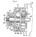
- Japanese Patent Application Laid-open No.2001 - 99197 discloses, as shown in Fig.9, a pulley unit having a one-way clutch comprising a frame (51) forming a front end of an engine starter (50); a clutch output shaft (52) having a shaft portion (52a), a disk portion (52b) and an outer cylinder portion (52c) and which is rotatably supported by the frame (51) through a bearing (53) disposed between a front portion of the frame (51) and the shaft portion (52a); a clutch input shaft (54) rotatably supported by a rear projection of the shaft portion (52a) of the clutch output shaft (52) through a bearing(55); a plurality of sprags (56) which is disposed between the outer cylinder portion (52c) of the clutch output shaft (52) and the clutch input shaft (54), and which meshes between both the input shaft (54) and the output shaft (52) if both the shafts (52) and (54) are relatively rotated in one direction (lock direction), and which
- the pulley unit having the one-way clutch According to the pulley unit having the one-way clutch, if a DC motor (59) of the engine starter (50) rotates at a high speed, this rotation is decelerated by a planetary gear speed reducer (60) and transmitted to the clutch input shaft (54), the rotation of the clutch input shaft (54) is transmitted to the clutch output shaft (52) through the sprags (56). The rotation transmitted to the clutch output shaft (52) is transmitted by the pulley (57), so that the pulley (57) rotates and drives the engine through the belt, thereby driving the engine.
- a DC motor (59) of the engine starter (50) rotates at a high speed
- this rotation is decelerated by a planetary gear speed reducer (60) and transmitted to the clutch input shaft (54)
- the rotation of the clutch input shaft (54) is transmitted to the clutch output shaft (52) through the sprags (56).
- the rotation transmitted to the clutch output shaft (52) is transmitted by the pulley
- the sprags (56) separate from the clutch input shaft (54) and thereafter, the clutch output shaft (52) and the pulley (57) can rotate without receiving resistance from the clutch input shaft (54).
- It is an object of this conventional invention is to use the pulley unit having the one-way clutch for a starter in a belt transmission system for an internal combustion engine which transmits starting torque to a crankshaft through a belt.
- the clutch output shaft (52) is rotated integrally with the pulley (57) during rotation of the pulley (57), but since a portion of the clutch output shaft (52) does not contribute to the driving of the engine, not only the shaft portion (52a), but also its disk portion (52b) and outer cylinder portion (52c) are rotated, which is a great factor of energy loss.
- a one-way clutch having an inner ring, an outer ring and an operation member (e.g., sprag, spring or the like) disposed between these rings is provided between the shaft and the pulley disposed concentrically around the shaft, and a portion which rotates together with the pulley is reduced.
- an operation member e.g., sprag, spring or the like
- the one-way clutch is a roller type clutch instead of the sprag type clutch, comprising, e.g., an inner ring; an outer ring; a cam surface provided on an inner peripheral surface of the outer ring; rollers as a plurality of meshing members which is disposed in a wedge-shaped space formed by the cam surface and an outer peripheral surface of the inner ring, which meshes between the inner ring and the outer ring if the inner ring and the outer ring are relatively rotated in one direction and which releases the meshed state when the inner ring and the outer ring are relatively rotated in the other direction; and a coil spring as a biasing member which biases the roller in a meshing direction (in a direction of the wedge-shaped space), in which the roller is biased in the meshing direction by the coil spring, and the roller is moved in the meshing-releasing direction by centrifugal force.
- a roller type clutch instead of the sprag type clutch, comprising, e.g., an inner ring; an
- roller type one-way clutch is to be disposed between the shaft and the pulley which is concentrically disposed around the shaft, however, since an outer diameter of the pulley is limited, an inner diameter of the outer ring of the one-way clutch becomes naturally small and with this, P.C.D. (Pitch Circle Diameter) of the roller also becomes small, centrifugal force acting on the roller becomes small, and there is a problem that the roller and the inner ring of the one-way clutch are into non-contact with each other.
- P.C.D. Peak Circle Diameter
- the present invention provides a pulley unit having a one-way clutch comprising a one-way clutch which has an inner ring, an outer ring, a meshing member disposed between both the rings, and a biasing member for biasing the meshing member in a meshing direction, and which is disposed between a shaft and a pulley concentrically disposed around the shaft, wherein at least one bearing is provided between the shaft and the pulley.
- the meshing member and the biasing member are rotated integrally with the outer ring, the meshing member is moved in a meshing-releasing direction by a centrifugal force if a rotation speed of the outer ring becomes equal to or greater than a predetermined speed, and a biasing force of the biasing member has enough magnitude to allow this movement.
- the one-way clutch may be of a sprag type having a sprag as the meshing member and the spring for biasing the sprag as the operation member, or may be of a roller type having a roller as the meshing member and a spring for biasing the roller as the operation member.
- the one-way clutch has a structure (outer ring cam type) comprising a cam surface provided on an inner peripheral surface of the pulley as the outer ring, a plurality of rollers as a plurality of meshing members which are disposed in a wedge-shaped space formed by the cam surface and an outer peripheral surface of the shaft as the inner ring, and which meshes between the shaft and the pulley when the shaft and the pulley are relatively rotated in one direction, and which releases the meshing state when the shaft and the pulley are relatively rotated in the other direction, and a coil spring as the biasing member for biasing the roller in the meshing direction (toward a narrow side of the wedge-shaped space).
- a structure outer ring cam type
- the pulley unit having the one-way clutch if it is used as a belt driving starter of an engine, the meshing member and the biasing member are integrally rotated with the outer ring at the time of starting but after that, if the rotation speed of the outer ring becomes equal to or higher than a predetermined speed, only the pulley is rotated, and energy loss which is caused when a portion which does not contribute to the driving of the engine is rotated can be suppressed.
- the pulley and the outer ring of the one-way clutch are integrally formed.
- P.C.D of the meshing member of the one-wayclutch (sprag, roller) can be increased while suppressing the outer diameter of the pulley and as a result, a centrifugal force acting on the meshing member becomes great, and the non-contact state between the meshing member and the shaft at the time of idling can be secured.
- the one-way clutch is provided between the shaft and an axially intermediate portion of the pulley, a roller bearing and a ball bearing are disposed between the shaft and the pulley through the one-way clutch.
- the pulley can rotate at high speed, and this unit can be used suitably as a belt driving starter of an engine of an automobile.
- the shaft is hollow, and the pulley has a belt-winding portion around which a belt is wound, and a diametrical distance T1 between an innermost diameter portion of an outer periphery of the pulley in the belt-winding portion and a center of the meshing member is smaller than a diametrical distance T2 between a center of the meshing member in a meshing starting position and a minimum inner diameter portion of an inner periphery of the shaft.
- P.C.D of the meshing member can be increased while suppressing the outer diameter of the pulley, and the centrifugal force acting on the meshing member can further be increased.
- the outer ring has a cam surface, the cam surface and an outer peripheral surface of the inner ring form a wedge-shaped space, the meshing member is a roller disposed in the wedge-shaped space, the one-way clutch further has a holder for holding the roller and the biasing member, and a roller holding portion which is formed in a wider portion in the wedge-shaped space by a roller holding surface provided on an inner periphery of the outer ring and a roller holding surface provided on an inner periphery of the holder, and which holds the roller which moved in the meshing-releasing direction in a non-contact state with the inner ring.
- the spring is a coil spring.for example, but the spring may be a leaf spring or the like.
- the center shaft of the spring is positioned such that the center shaft substantially coincides with a moving direction of the meshing member when the centrifugal force is applied.
- a diametrical size (in a transverse cross section) of a portion of the spring abutting against the roller is smaller than a diameter of the roller, and the roller holding portion is provided with a roller holding surface of the outer ring and a roller holding surface of the holder such that the abutting portion of the spring against the roller is sandwiched from opposite sides (such that the transverse cross section becomes substantially folding-fan shape).
- the roller and the spring held by the holder rotate integrally with the outer ring, and the roller moves in the meshing-releasing direction by a centrifugal force when the rotation speed of the outer ring becomes equal to or higher than a predetermined speed.
- the roller which moved in the meshing-releasing direction is held in the non-contact state with respect to the inner ring by the roller holding portion provided on a wider side in the wedge-shaped space.
- the roller holding portion is formed by the roller holding surface provided on the inner periphery of the outer ring and the roller holding surface provided on the inner periphery side of the holder, the roller is prevented from tilting by vibration or the like and thus, heat which may be caused by contact between the roller and the raceway surface of the inner ring and clogging of the roller are prevented.
- the holder is provided with a spring end positioning surface for preventing the spring from moving in the axial direction, a spring inner side positioning surface for preventing the spring from moving inward which is perpendicular to a spring axis, and a spring outer side positioning surface for preventing the spring from moving outward which is perpendicular to the spring axis.
- the roller holding surface of the outer ring is provided between the cam surface and the spring outer side positioning surface, and the roller holding surface of the holder is continuously provided with the spring inner side positioning surface.
- the roller moves and the spring is deformed in association with each other reliably, and even if lock free is repeated, function thereof can reliably be exhibited.
- the roller holding surface of the outer ring is a recessed surface having an arc transverse cross section.
- the roller holding surface of the holder also may be a recessed surface having an arc transverse cross section.
- the roller holding surface of the holder may be a slant surface connected to the spring inner side positioning surface.
- the outer ring has a cam surface, the cam surface and an outer peripheral surface of the inner ring form a wedge-shaped space in which the meshing member is disposed, the biasing member is a spring which biases the meshing member toward a narrow portion of the wedge-shaped space, the one-way clutch further has a holder for holding the meshing member and the spring, the spring has a center shaft which is inclined in a tangent direction of the outer peripheral surface of the inner ring so that the spring can be deformed in a direction in which a biasing force of the spring biasing the meshing member is reduced when a centrifugal force is applied, and the spring has a spring end positioning surface for preventing the spring from moving in an axial direction of the spring, a spring inner side positioning surface for preventing the spring from moving inward which is perpendicular to a spring axis, and a spring outer side positioning surface for preventing the spring from moving outward which is perpendicular to the spring axis.
- the spring is a coil spring for example, but the spring may be a leaf spring or the like.
- the center shaft of the spring is positioned such that the center shaft substantially coincides with the moving direction of the meshing member when the centrifugal force is applied. It is not always necessary that a moving direction of the center shaft and a moving direction of the meshing member when the centrifugal force is applied coincide with each other.
- the meshing member held by the holder and the spring are integrally rotated with the outer ring, and the meshing member moves in the meshing-releasing direction by a centrifugal force when the rotating speed of the outer ring becomes equal to or higher than a predetermined speed. Since the center shaft is inclined with respect to the outer peripheral surface of the inner ring, the centrifugal force acting on the spring has a component in the axial direction of the spring in addition to a component perpendicular to the center shaft of the spring. Therefore, a biasing force of the spring when the centrifugal force is applied is a sum of the original resilient force of the spring and the axial component of the centrifugal force.
- the spring When the centrifugal force is applied, the spring is deformed in a direction reducing the biasing force with respect to the meshing member.
- the biasing force of the spring when the centrifugal force is applied becomes smaller than the original resilient force of the spring. Therefore, if the centrifugal force is applied when the rotation speed of the outer ring becomes equal to or greater than a predetermined speed, the meshing member can easily moved in the meshing-releasing direction (toward the wide side of the wedge-shaped space). If the centrifugal force is not applied, the biasing force of the of the spring becomes original resilient force of the spring and increases, and the meshing member can easily move in the meshing direction (toward the narrow side of the wedge-shaped space).
- the spring can not move other than in a direction deforming in the axial direction by the spring end positioning surface, the spring inner side positioning surface, and the spring outer side positioning surface, the spring is deviated when the meshing member moves, and the biasing force direction of the spring when the outer ring is stopped is not changed, and there is no problem that the roller can not move in the meshing direction smoothly. In this manner, movement of the coil spring toward the narrow side of the wedge-shaped space by the biasing force and movement of the roller toward the wide side of the wedge-shaped space when the centrifugal force is applied are reliably repeated, and even if lock free is repeated, function thereof can reliably be exhibited.
- a projection which is concentric with the center shaft may be provided.
- a gap between the projection and the inner peripheral surface of the coil spring is made greater than a gap between the inner peripheral surface of the coil spring and the end positioning surface, the spring inner side positioning surface, or the spring outer side positioning surface.
- the spring end positioning surface and the spring inner side positioning surface are provided on the holder, and the spring outer side positioning surface is provided on the outer ring inner periphery.
- the center shaft of the spring can be set precisely, and since the holder is provided with the spring end positioning surface and the spring inner side positioning surface, the processing of the outer ring which requires strength can be simplified.
- grease having ether base oil is charged between the outer ring and the inner ring.
- ether-based base oil is alkyl diphenyl ether.
- Antioxidant, anticorrosive additive, extreme pressure additive, solid lubricant or the like is appropriately added to the grease.
- Pressure viscosity coefficient of the grease is 10G/Pa or higher.
- the ether-based base oil has excellent thermal stability, and when it is used as a belt driving starter of an automobile engine in which idling state is carried out for extremely long time, the base oil exhibit excellent durability.
- thickener of the grease is urea.
- the ether-based base oil constituting the grease has excellent thermal stability, and if the base oil is combined with the urea-based thickener, excellent wear resistance of the grease is exhibited. Therefore, when this base oil is used as a belt driving starter of an automobile engine in which idling state is carried out for extremely long time, the base oil exhibit excellent durability.
- a producing method of an inner ring of a one-way clutch according to the present invention is suitable when the above-described pulley unit having a one-way clutch.
- the producing method of an inner ring used in a one-way clutch comprising an inner ring, an outer ring, a meshing member disposed between both the rings, and a biasing member for biasing the meshing member in a meshing direction, the outer ring is provided with a cam surface, and the meshing member and the inner ring are brought into non-contact state when a centrifugal force is applied, said method comprising a step for processing an outer diameter and an inner diameter by cold forging.
- the producing cost of the one-way clutch can be reduced.
- the method further comprises a step for processing a raceway surface of the bearing on an outer diameter by turning after the cold forging step, and the inner ring of the one-way clutch and the inner ring of the bearing are integrally produced.
- a seal groove in which a sealing member is fitted is processed in addition to the raceway surface of the bearing.
- the one-way clutch is sandwiched between bearings.
- One of the bearings is a roller bearing having a a roller as a rolling element, and the other is a ball bearing having a ball as a rolling element.
- the method further comprises a step for carrying out a thermal processing after the turning step, wherein the thermal processing step comprises a first step for carrying out carburization processing or carburization hardening processing, a second step for carrying out hardening processing to precipitate fine spherical carbide in a carburization layer, and a third step for carrying out high density carburization hardening processing such that a carbon density on a surface becomes higher than a carbon density on a surface obtained by the first step.
- the thermal processing step comprises a first step for carrying out carburization processing or carburization hardening processing, a second step for carrying out hardening processing to precipitate fine spherical carbide in a carburization layer, and a third step for carrying out high density carburization hardening processing such that a carbon density on a surface becomes higher than a carbon density on a surface obtained by the first step.
- a minimum distance between spherical carbides dispersed and precipitated in a carburization layer matrix of the inner ring of the one-way clutch is set to 15 ⁇ or less (more preferably, 10 ⁇ or less).
- the minimum distance between the spherical carbides is set to 15 ⁇ or less, rolling durability in dirty oil and clean oil is elongated.
- the steel material there is used a known steel such as JIS SUJ2, JIS SCr420, SAE5120 or the like, or a steel comprising 15 to 0.45% CO by weight, 1.2 to 1.6% Cr by weight, 0.35 to 0.55% Si by weight, 0.35 to 0.65% Mn by weight, a balance of Fe, and inevitable impurities.
- a known steel such as JIS SUJ2, JIS SCr420, SAE5120 or the like, or a steel comprising 15 to 0.45% CO by weight, 1.2 to 1.6% Cr by weight, 0.35 to 0.55% Si by weight, 0.35 to 0.65% Mn by weight, a balance of Fe, and inevitable impurities.
- a heating temperature in the third step is lower than a heating temperature in the second step. If the heating temperature in the third step becomes higher than the heating temperature in the second step, there is an adverse possibility that a portion of carbide precipitated in the second step is dissolved in the matrix. Such a method will be explained in more detail.
- the method comprises a first step for heating for three to five hours at a temperature of 930 to 950° in carburization atmosphere including C 3 H 8 and then, oil cooling; a second step for heating for 0.5 to 0.8 hours at a temperature of 800 to 840° and then, oil cooling; and a third step for heating for three to five hours at a temperature of 790 to 840° and equal to or lower than that of the second step in a carburization atmosphere including C 3 H 8 and then, oil cooling.
- a surface hardness of the inner ring is 58 to 67 with a Rockwell hardness C (HRC, hereinafter). If the surface hardness is lower than HRC58, the surface hardness is not sufficient, and when a one-way clutch using this inner ring is used in a dirty oil in which foreign matters are mixed, flaw such as indentation caused by foreign matter which becomes a peel-off starting point is prone to be generated on a surface of the inner ring, wear-resistance is lowered, and lifetime of the bearing is shortened, and if the surface hardness exceeds HRC67, toughness is lowered.
- HRC Rockwell hardness C
- average particle diameter of the spherical carbide is equal to or lower than 5 ⁇ m. If the average particle diameter of the spherical carbide exceeds 5 ⁇ m, there is an adverse possibility that spherical carbides whose average particle diameter exceed 5 ⁇ m assumes about 80% of total carbides and as a result, stress concentrates on the spherical carbide exceeding 5 ⁇ m, and destroy is generated from this portion. Therefore, the average particle diameter of the spherical carbide should be equal to or lower than 5 ⁇ m or lower, more preferably, lower than 3 ⁇ m.
- spherical carbides whose particle diameter is less than 5 ⁇ m assume lower than 70%, this means that spherical carbides whose particle diameter exceed 5 ⁇ m assume 30% or more, and maximum diameter is 10 ⁇ m and as a result, stress concentrates on spherical carbides whose particle diameter exceed 5 ⁇ m, and there is an adverse possibility that destroy is generated from this portion. Therefore, it is preferable that spherical carbides whose particle diameter is 5 ⁇ m or less assume 70% of total.
- Fig. 1 shows a pulley unit having a one-way clutch of this invention.
- a pulley unit (1) having the one-way clutch is disposed in a portion of the engine which connects a driving section and a recessed surface of a starter motor.
- a one-way clutch (5) is provided between a hollow shaft (3) fitted to the rotation shaft (2) of the starter motor and a pulley (4) concentrically disposed around the hollow shaft (3).
- the pulley (4) is provided at its outer periphery with a belt-winding portion (4a) around which a V-ribbed belt (B) is wound.
- the one-way clutch (5) is provided between the hollow shaft (3) and an intermediate portion of the pulley (4) in its axial direction. Between ends of the hollow shaft (3) and the pulley (4), a roller bearing (6) and a ball bearing (7) are provided such as to sandwich the one-way clutch (5).
- the pulley (4), an outer ring of the one-way clutch (5) and outer rings of the bearings (6) and (7) are integrally formed together, and the hollow shaft (3), the inner ring of the one-way clutch (5) and inner rings of the bearings (6) and (7) are integrally formed together so that the number of parts is reduced.
- Seal members (8) and (9) are respectively disposed at axially outsides of the roller bearing (6) and the ball bearing (7).
- Another seal member (10) is disposed at a free end (left end in the drawing) of the pulley unit for preventing muddy water from entering the pulley unit.
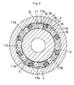
- the one-way clutch (5) comprises a cam surface (11) disposed on an inner peripheral surface of the pulley (4); rollers (13) as a plurality of meshing members; a coil spring (14) as a biasing member for biasing the rollers (13) toward a narrow side of a wedge-shape space (12) in a meshing direction; and a holder (15) for positioning the rollers (13) in the wedge-shape space (12).
- the rollers (13) are disposed in the wedge-shape space (12) formed by the cam surface (11) and an outer peripheral surface of the hollow shaft (3).
- the rollers (13) mesh between the hollow shaft (3) and the pulley (4), and if the hollow shaft (3) and the pulley (4) are relatively rotated in the other direction (free direction), the rollers (13) release the meshing state.
- the cam surface (11) comprises a plurality sets (four sets in this embodiment) of parallel two surfaces (11a), (11b), (11c) and (11d) arranged in the circumferential direction such as to be opposed to each other while sandwiching its axial center.
- Each of the surfaces of the parallel two surfaces (11a), (11b), (11c) and (lid) forms not a right angle with respect to a normal (19) passing a center of the roller (13) and the axial center. but forms an acute angle slightly smaller than a right angle as shown in Fig.3 which is an enlarged view of a portion of Fig.2.
- the pulley (4) has a cam surface (11)
- the pulley (4) has a function as the outer ring of the one-way clutch (5), and the pulley (4) and the outer ring of the one-way clutch (5) are integrally formed together.
- a wide side end of the wedge-shape space (12) of each of the parallel two surfaces (11a), (11b), (11c) and (lid) is provided with a holding recessed surface (16) for stopping the roller (13) which has an arc transverse cross section and receives a centrifugal force.
- the recessed surface (16) is an arc having substantially the same radius as that of the outer peripheral surface of the roller (13).
- an inner diameter of the pulley (4) has a step.
- a diametrical distance T1 between an innermost diameter portion of the outer periphery of the pulley in the belt-winding portion (4a) and a center of the rollers (13) in the meshing starting position is smaller than a diametrical distance T2 between the center of the rollers (13) in the meshing starting position and a minimum inner diameter portion of the inner periphery of the hollow shaft (3). That is, if substantial thicknesses of the pulley (4) and the hollow shaft (3) are compared, the thickness of the pulley (4) is thinner. With this structure. it is possible to increase the P.C.D of the roller (13) while suppressing the outer diameter of the pulley (4), and a centrifugal force acting on the roller (13) becomes greater.
- the coil spring (14) has a center shaft in its transverse cross section, the coil spring (14) is of elliptic shape, and its direction of long diameter coincides with an axial direction of the one-way clutch (5).
- a length of its short diameter, i.e., a size in a diametrical direction of a portion of the coil spring (14) abutting against the roller is smaller than a diameter of the roller (13).
- the holder (15) is made of synthetic resin, and has an outer peripheral shape substantially along the cam surface (11) and an inner peripheral shape along the outer peripheral surface of the hollow shaft (3), and is press-fitted into the cam surface (11). A slight gap is provided between the holder (15) and the outer periphery of the hollow shaft (3).
- the holder (15) is provided with a spring-receiving recess (17) for positioning the coil spring (14). Grease is charged into the spring-receiving recess (17).
- the spring-receiving recess (17) is connected to the roller holding recessed surface (16) of the cam surface (11), and constantly maintains a direction of the center shaft of the coil spring (14) by cooperation with a spring positioning surface (18) provided on the inner periphery of the pulley (4).
- the center shaft of the coil spring (14) is inclined with respect to a tangent direction of the outer peripheral surface of the hollow shaft (3) so that when a centrifugal force is applied to the coil spring (14), the center shaft can be deformed in a direction reducing a biasing force against the roller (13).
- the spring positioning surface (18) of the pulley (4) comprises four sets of parallel two surfaces opposed to each other while sandwiching a shaft center of the one-way clutch (5).
- the four sets of parallel two surfaces are arranged in the circumferential direction.
- the spring-receiving recess (17) comprises a spring end positioning surface (17a) for preventing the coil spring (14) from moving in an axial direction of the spring, and a spring inner side positioning surface (17b) for preventing the coil spring (14) from moving inward perpendicular to the spring axis.
- the spring positioning surface (18) of the pulley (4) is a spring outer side positioning surface for preventing the coil spring (14) from moving outward perpendicular to the spring axis.
- Fig.5 is a diagram of a portion of the holder (15) which is viewed from diametrically outside. As shown with symbols (17d) and (17e) in Fig.5, the spring-receiving recess (17) has axial direction-positioning surfaces (17d) and (17e) for preventing the coil spring (14) from moving in the axial direction of the one-way clutch (5).
- a roller holding slant surface (17c) is connected to the spring inner side positioning surface (17b) of the spring-receiving recess (17).
- the other end of the slant surface (17c) has a slight gap between itself and the outer peripheral surface of the hollow shaft (3).
- Figs.2 and 3 show a state in which a centrifugal force is not applied to the roller (13) and the coil spring (14). If the hollow shaft (3) is rotated in a counterclockwise direction in this state, the roller (13) meshes between the hollow shaft (3) and the pulley (4), and the hollow shaft (3) and the pulley (4) are rotated integrally.
- the recessed surface (16) which is the roller holding surface is the arc in transverse cross section having substantially the same radius as that of the outer peripheral surface of the roller (13). Therefore, an outer peripheral portion of the roller (13) having the cylindrical surface is just fitted into the recessed surface (16), and the slant surface (17c) which is the roller holding surface of the holder (15) appears from diametrically inside.
- the roller (13) is not inclined, and a gap between the outer periphery of the hollow shaft (3) and the roller (13) is secured, and the non-contact state between the hollow shaft (3) and the roller (13) is established.
- the above pulley unit having the one-way clutch When the above pulley unit having the one-way clutch is used for a belt driving starter, it is required for grease to have excellent meshing ability, wear resistance and thermal stability.
- the meshing ability and the wear resistance with respect to the meshing ability are characteristics required for general one-way clutches, but were resistance with respect to the thermal stability and slip are characteristics required when idling is frequently used, and if both the wear resistance and thermal stability are satisfied, durability of the pulley unit having a one-way Clutch is secured.
- condition of the belt driving starter is that angular acceleration is 300 to 400 red/sec 2 , and a temperature is about 10 to 200°.
- base oil is ether.
- ether-based base oil is alkyl diphenyl ether.
- a antioxidant, anticorrosive additive, extreme pressure additive, solid lubricant or the like is appropriately added to the grease.
- the pressure viscosity coefficient of the grease is 10G/Pa or higher.
- a thickener of the grease is urea.
- Table 1 shows a relation between kinds and characteristics of the base oil of the grease. From the Table, concerning the thermal stability, ether-based polyphenyl ether is most excellent, but polyphenyl ether is inferior in wear resistance, and it is necessary to enhance the wear resistance in order to enhance the durability.
- Table 3 shows a result of evaluation of characteristics of five kinds of greases and wear
- Fig.6 shows a result of measurement of a relation of pressure viscosity coefficient and wear depth of grease measured for two kinds of greases (two kinds, i.e., grease having ether-based base oil and urea as thickener, and Li soap).
- thickener pressure viscosity coefficient G/Pa
- Wear depth ⁇ m
- Polyol ester urea 11 4 Alkyl diphenyl ester urea 11.1 4 Diester Li soap 9.5 12 Ester Li soap 10.9 27
- a solid line indicates a egression curve using the urea-based thickener. It is found from the results in Table 3 and Fig.6 that if the urea-based thickener is used and the pressure viscosity coefficient is set to 10G/Pa or higher, even if ether-based (alkyl diphenyl ether in this example) base oil which is inferior in wear resistance to polyol ester is used, the wear depth in the cam surface (11) of the roller (13) by meshing in the one-way clutch at the time of meshing is not inferior as compared with grease using polyol ester as the base oil.
- the polyphenyl ether is superior to polyol ester in thermal stability, and it is found that a grease using alkyl diphenyl ether as the base oil and urea-based compound as thickener exhibit extremely excellent durability together with the wear resistance and the thermal stability.
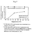
- Fig.7 shows a relation between a temperature and acceleration in which meshing slip is generated in grease 1) (shown with broken line) in which base oil which is one example of grease using ether-base base oil and thickener is urea-based compound, and grease 2) (shown with solid line) in which base oil is polyol ester and thickener is urea-based compound.
- This pulley unit having the one-way clutch is actuated in the following manner.
- the hollow shaft (3) which is integral with the rotation shaft (2) of the starter motor is rotated in a counterclockwise direction.
- the rollers (13) are meshed in the narrow side of the wedge-shape space (12) of the one-way clutch (5), the driving force is transmitted, and the hollow shaft (3) and the pulley (4) are integrally rotated.
- the pulley (4) is connected to a crankshaft through a belt, and the engine is started by rotation of the pulley (4).
- the starter is stopped, and the pulley (4) keeps rotating in the counterclockwise direction.
- each of the rollers (13) is positioned by the recessed surface (16) having substantially the same curvature as that of the roller (13), and the hollow shaft (3) is brought into the non-contact state.
- the coil spring (14) receives a force in a direction shrunk by the centrifugal force, a resilient force for biasing the roller (13) in the meshing direction is reduced, and the non-contact state between the roller (13) and the hollow shaft (3) is secured.
- the coil spring is indicated as means for biasing the roller (13), it is also possible to use, instead of the coil spring, a leaf spring or the like.
- the meshing member of the one-way clutch is roller (13) in the above description, a one-way clutch whose meshing member is sprag can also be used only if the one-way clutch is constituted such that the meshing member and the biasing member are rotated integrally with the outer ring, the meshing member moves in the meshing-releasing direction by a centrifugal force when the rotation speed of the outer ring is equal to or higher than a predetermined speed, and the biasing force of the biasing member has enough magnitude for permitting this movement.
- the outer diameter of the hollow shaft (3) is provided with seal grooves (8a), (9a) and (10a) into which inner diameter portions of the raceway surface (7a) of the ball bearing (7) and the seal members (8), (9) and (10) are fitted.
- the inner diameter portion of the hollow shaft (3) is provided with a female thread portion (3a) threaded to a male thread portion provided on an end of the rotation shaft (2), and a hexagonal engaging groove (3b) into which a hexagonal wrench used when the hollow shaft (3) is rotated and threadedly engaged with the end of the rotation shaft (2).
- the hollow shaft (3) can be processed by cold forging not by shaving and with this, the processing cost of the pulley unit having a one-way clutch can be reduced. It is preferable that HRC of the hollow shaft (3) is 58 to 67 (e.g., about 64).
- the hollow shaft (3) i.e., the inner ring of the one-way clutch is produced by steps shown in Fig.8.
- steel material SAE5120 is selected. Then, an outer diameter and an inner diameter thereof are processed by cold forging. The outer diameter is formed into a cylindrical surface, and the inner diameter is formed with the female thread portion (3a) and the hexagonal engaging groove (3b). Next, an outer diameter of the material is formed with the raceway surface (7a) and seal grooves (8a). (9a) and (10a) for the seal members (8), (9) and (10). Next, the material is subjected to thermal processing and then, a surface of the material is ground to obtain the hollow shaft (3).
- the thermal processing is carried out using a fluid layer furnace.
- the thermal processing comprises a first step in which N 2 gas is supplied as fluidization gas and C 3 H 8 gas is supplied and it is heated for three hours at 930°C and then, it is oil cooled to 80°C, carburization hardening (or carburization processing) is carried out; a second step in which N 2 gas is supplied as fluidization gas and it is heated for 0.5 hour at 840°C and then it is oil cooled to 80°C to carry out hardening processing; and a third step in which N 2 gas is supplied as fluidization gas and C 3 H 8 gas is supplied and it is heated for five hours at 830°C and then, it is oil cooled to 80°C, and high density carburization hardening processing is carried out.
- the second step fine spherical carbide is precipitated in a carburization layer
- the third step carbon density on the surface becomes higher than that on the surface obtained by the first step.
- a distance between spherical carbides dispersed and precipitated in a carburization layer matrix of the inner ring of the one-way clutch is set to 15 ⁇ or less (more preferably, 10 ⁇ or less). It is considered that a factor for reducing the minimum distance between most close particles to 15 ⁇ m or less resides in alloy composition of steel material used for forming the same or thermal processing condition including the carburization processing, but it is not clearly known how the alloy composition and the thermal processing condition influences the distance between the spherical carbides.
Landscapes
- Engineering & Computer Science (AREA)
- General Engineering & Computer Science (AREA)
- Mechanical Engineering (AREA)
- Pulleys (AREA)
- One-Way And Automatic Clutches, And Combinations Of Different Clutches (AREA)
Priority Applications (1)
| Application Number | Priority Date | Filing Date | Title |
|---|---|---|---|
| EP04010978A EP1457699A3 (de) | 2001-10-02 | 2002-10-02 | Riemenscheibe mit Einwegkupplung |
Applications Claiming Priority (6)
| Application Number | Priority Date | Filing Date | Title |
|---|---|---|---|
| JP2001306281 | 2001-10-02 | ||
| JP2001306281 | 2001-10-02 | ||
| JP2001336061A JP2003139166A (ja) | 2001-11-01 | 2001-11-01 | 一方向クラッチの内輪の製造方法 |
| JP2001336061 | 2001-11-01 | ||
| JP2001355542A JP3811813B2 (ja) | 2001-11-21 | 2001-11-21 | 一方向クラッチ付きプーリユニット |
| JP2001355542 | 2001-11-21 |
Related Child Applications (2)
| Application Number | Title | Priority Date | Filing Date |
|---|---|---|---|
| EP04010978A Division EP1457699A3 (de) | 2001-10-02 | 2002-10-02 | Riemenscheibe mit Einwegkupplung |
| EP04010978.7 Division-Into | 2004-05-08 |
Publications (3)
| Publication Number | Publication Date |
|---|---|
| EP1300602A2 true EP1300602A2 (de) | 2003-04-09 |
| EP1300602A3 EP1300602A3 (de) | 2003-06-04 |
| EP1300602B1 EP1300602B1 (de) | 2005-11-30 |
Family
ID=27347644
Family Applications (2)
| Application Number | Title | Priority Date | Filing Date |
|---|---|---|---|
| EP04010978A Withdrawn EP1457699A3 (de) | 2001-10-02 | 2002-10-02 | Riemenscheibe mit Einwegkupplung |
| EP02022119A Revoked EP1300602B1 (de) | 2001-10-02 | 2002-10-02 | Riemenscheibe mit Einwegkupplung |
Family Applications Before (1)
| Application Number | Title | Priority Date | Filing Date |
|---|---|---|---|
| EP04010978A Withdrawn EP1457699A3 (de) | 2001-10-02 | 2002-10-02 | Riemenscheibe mit Einwegkupplung |
Country Status (3)
| Country | Link |
|---|---|
| US (1) | US7143881B2 (de) |
| EP (2) | EP1457699A3 (de) |
| DE (1) | DE60207666T2 (de) |
Cited By (2)
| Publication number | Priority date | Publication date | Assignee | Title |
|---|---|---|---|---|
| EP2034207A3 (de) * | 2007-08-28 | 2010-06-02 | Denso Corporation | Drehmomentübertragungsvorrichtung zum Starten eines Motors und für die Vorrichtung verwendete Einwegkupplung |
| CN104343850A (zh) * | 2014-10-14 | 2015-02-11 | 宁夏元辰科技有限公司 | 滚柱式非接触式逆止器 |
Families Citing this family (28)
| Publication number | Priority date | Publication date | Assignee | Title |
|---|---|---|---|---|
| JP4158556B2 (ja) * | 2003-02-28 | 2008-10-01 | 株式会社ジェイテクト | 動力伝達装置 |
| JP4161740B2 (ja) * | 2003-02-28 | 2008-10-08 | 株式会社ジェイテクト | 一方向クラッチユニット |
| WO2006001309A1 (ja) * | 2004-06-23 | 2006-01-05 | Nsk Ltd. | 一方向クラッチ内蔵型回転伝達装置 |
| FR2885190A1 (fr) * | 2005-04-29 | 2006-11-03 | Coster Andre Martin De | Dispositif de freinage par excentrique pour l'irreversabilite automatique et immediate, dans les deux sens, de la transmission d'un couple de forces |
| FR2885191B1 (fr) * | 2005-04-29 | 2008-04-25 | Coster Andre Martin De | Dispositif de controle par excentrique pour l'irreversibilite automatique et immediate, dans les deux sens, de la transmission d'un couple de forces |
| WO2007012168A1 (en) * | 2005-07-27 | 2007-02-01 | Zen S/A Industria Metalúrgica | Pulley with a one-way clutch |
| JP2008095865A (ja) * | 2006-10-13 | 2008-04-24 | Jtekt Corp | 一方向クラッチ |
| FR2913081B1 (fr) * | 2007-02-27 | 2009-05-15 | Skf Ab | Dispositif de poulie debrayable |
| DE102009006354A1 (de) * | 2008-02-26 | 2009-08-27 | Schaeffler Kg | Verriegelung für einen Start-Stopp-Betrieb eines Startergenerators |
| US8944947B2 (en) * | 2008-03-26 | 2015-02-03 | Jtekt Corporation | Pulley unit |
| WO2009121188A1 (en) * | 2008-04-04 | 2009-10-08 | Litens Automotive Partnership | Auto-selecting two-ratio transmission |
| CA2737064A1 (en) * | 2008-09-15 | 2010-03-18 | Magna Powertrain Inc. | Sealed one way roller clutch |
| CA2737062A1 (en) * | 2008-09-15 | 2010-03-18 | Magna Powertrain Inc. | Torque transfer unit with sealed one way clutch for an engine starting system |
| EP2386032B1 (de) * | 2008-09-15 | 2019-06-19 | Magna Powertrain Inc. | Eingekapselte freilaufrollenkupplung von hoher kapazität |
| TWM367257U (en) * | 2008-10-22 | 2009-10-21 | Auto A J Prec Inc | Improved structure of one-way bearing |
| JP5227269B2 (ja) * | 2009-06-19 | 2013-07-03 | 三ツ星ベルト株式会社 | 動力伝達機構 |
| CN102713252B (zh) * | 2009-11-19 | 2014-10-29 | 麦格纳动力系有限公司 | 具有单向离合器的发动机起动系统 |
| DE102010031499A1 (de) * | 2010-07-19 | 2012-01-19 | Robert Bosch Gmbh | Handwerkzeugmaschine mit einem mechanischen Schlagwerk |
| WO2012139224A1 (en) | 2011-04-11 | 2012-10-18 | Litens Automotive Partnership | Multi-speed drive for transferring power to a load |
| DE102011080454A1 (de) * | 2011-08-04 | 2013-02-07 | Schaeffler Technologies AG & Co. KG | Freilauftrennkupplung mit einer Freilaufanordnung |
| CN103649595A (zh) * | 2011-11-25 | 2014-03-19 | 日本精工株式会社 | 带单向离合器内置型皮带轮的旋转机械装置 |
| CN203822850U (zh) * | 2014-03-24 | 2014-09-10 | 上海昶意机械制造有限公司 | 单向滚针轴承 |
| CN105257748B (zh) * | 2015-10-15 | 2017-08-29 | 浙江亚特电器有限公司 | 弹力件及采用该弹力件的过载离合器 |
| CN107651097B (zh) * | 2017-09-25 | 2023-06-16 | 浙江雅迪机车有限公司 | 一种电动车的侧挂电机 |
| DE102017127601A1 (de) * | 2017-11-22 | 2019-05-23 | Seg Automotive Germany Gmbh | Freilaufeinrichtung für einen Starter und Starter für eine Brennkraftmaschine |
| US11773857B2 (en) | 2018-10-12 | 2023-10-03 | Baker Hughes Holdings Llc | Dual ESP with selectable pumps |
| DE102019114455A1 (de) * | 2019-05-29 | 2020-12-03 | Seg Automotive Germany Gmbh | Freilaufeinrichtung für einen Starter und Starter für eine Brennkraftmaschine |
| US11649827B2 (en) * | 2019-09-26 | 2023-05-16 | Baker Hughes Oilfield Operations Llc | Systems and methods for prevention of rotation in permanent magnet motors |
Citations (6)
| Publication number | Priority date | Publication date | Assignee | Title |
|---|---|---|---|---|
| US2543482A (en) * | 1947-08-07 | 1951-02-27 | American Pulley Co | Reverse rotation check means |
| JPH08177888A (ja) * | 1994-10-27 | 1996-07-12 | Zero Eng:Kk | 遠心式ワンウェイクラッチ |
| US5876298A (en) * | 1996-07-10 | 1999-03-02 | Denso Corporation | Speed reduction device having overrunning clutch |
| FR2774446A1 (fr) * | 1998-02-05 | 1999-08-06 | Koyo Seiko Co | Ensemble formant poulie equipe d'un embrayage unidirectionnel |
| EP0947721A2 (de) * | 1998-04-02 | 1999-10-06 | Koyo Seiko Co., Ltd. | Einwegkupplung |
| EP1101978A1 (de) * | 1999-11-19 | 2001-05-23 | Koyo Seiko Co., Ltd. | Riemenscheibe mit Einwegkupplung |
Family Cites Families (16)
| Publication number | Priority date | Publication date | Assignee | Title |
|---|---|---|---|---|
| US2044197A (en) * | 1934-01-10 | 1936-06-16 | Barthel Hermann | Roller clutch |
| US3935749A (en) * | 1974-09-05 | 1976-02-03 | Vln Corporation | Starting apparatus |
| FR2377531A1 (fr) * | 1977-01-17 | 1978-08-11 | Paris & Du Rhone | Perfectionnements aux lanceurs de demarreurs electriques |
| US4415072A (en) * | 1980-04-10 | 1983-11-15 | Nsk-Warner K. K. | One-way clutch |
| JPS58145522A (ja) * | 1982-02-20 | 1983-08-30 | Honda Motor Co Ltd | 車両用動力伝達装置 |
| DE3409692A1 (de) * | 1984-03-16 | 1985-09-19 | Daimler-Benz Ag, 7000 Stuttgart | Antriebsanordnung eines kraftfahrzeuges mit einer hydrodynamischen stroemungskupplung und einem von hand schaltbaren gangwechselgetriebe |
| US4735299A (en) * | 1985-03-29 | 1988-04-05 | Yamaha Hatsudoki Kabushiki Kaisha | One-way clutch and improved spring therefor |
| JP2807722B2 (ja) * | 1990-08-03 | 1998-10-08 | 光洋精工株式会社 | 一方向クラッチ |
| JPH0746821Y2 (ja) * | 1990-08-03 | 1995-10-25 | 光洋精工株式会社 | 一方向クラッチ |
| JP3170608B2 (ja) * | 1992-01-24 | 2001-05-28 | 光洋精工株式会社 | 一方向クラッチ装置 |
| JP2904660B2 (ja) * | 1992-10-15 | 1999-06-14 | 光洋精工株式会社 | 一方向クラッチ |
| JP3655063B2 (ja) * | 1997-08-25 | 2005-06-02 | 光洋精工株式会社 | オルタネータ用一方向クラッチ |
| JP3731702B2 (ja) * | 1997-09-24 | 2006-01-05 | 光洋精工株式会社 | プーリユニット |
| JPH11218144A (ja) * | 1997-11-17 | 1999-08-10 | Nippon Seiko Kk | ワンウェイクラッチ内蔵転がり軸受 |
| JP3652207B2 (ja) * | 2000-03-28 | 2005-05-25 | 日本精工株式会社 | 一方向クラッチ内蔵型回転伝達装置 |
| US6848552B2 (en) * | 2003-04-16 | 2005-02-01 | Ntn Corporation | Starter pulley with integral clutch |
-
2002
- 2002-10-02 US US10/262,079 patent/US7143881B2/en not_active Expired - Fee Related
- 2002-10-02 EP EP04010978A patent/EP1457699A3/de not_active Withdrawn
- 2002-10-02 EP EP02022119A patent/EP1300602B1/de not_active Revoked
- 2002-10-02 DE DE60207666T patent/DE60207666T2/de not_active Revoked
Patent Citations (6)
| Publication number | Priority date | Publication date | Assignee | Title |
|---|---|---|---|---|
| US2543482A (en) * | 1947-08-07 | 1951-02-27 | American Pulley Co | Reverse rotation check means |
| JPH08177888A (ja) * | 1994-10-27 | 1996-07-12 | Zero Eng:Kk | 遠心式ワンウェイクラッチ |
| US5876298A (en) * | 1996-07-10 | 1999-03-02 | Denso Corporation | Speed reduction device having overrunning clutch |
| FR2774446A1 (fr) * | 1998-02-05 | 1999-08-06 | Koyo Seiko Co | Ensemble formant poulie equipe d'un embrayage unidirectionnel |
| EP0947721A2 (de) * | 1998-04-02 | 1999-10-06 | Koyo Seiko Co., Ltd. | Einwegkupplung |
| EP1101978A1 (de) * | 1999-11-19 | 2001-05-23 | Koyo Seiko Co., Ltd. | Riemenscheibe mit Einwegkupplung |
Non-Patent Citations (1)
| Title |
|---|
| PATENT ABSTRACTS OF JAPAN vol. 1996, no. 11, 29 November 1996 (1996-11-29) & JP 08 177888 A (ZERO ENG:KK), 12 July 1996 (1996-07-12) * |
Cited By (3)
| Publication number | Priority date | Publication date | Assignee | Title |
|---|---|---|---|---|
| EP2034207A3 (de) * | 2007-08-28 | 2010-06-02 | Denso Corporation | Drehmomentübertragungsvorrichtung zum Starten eines Motors und für die Vorrichtung verwendete Einwegkupplung |
| CN104343850A (zh) * | 2014-10-14 | 2015-02-11 | 宁夏元辰科技有限公司 | 滚柱式非接触式逆止器 |
| CN104343850B (zh) * | 2014-10-14 | 2017-02-15 | 宁夏元辰科技有限公司 | 滚柱式非接触式逆止器 |
Also Published As
| Publication number | Publication date |
|---|---|
| US7143881B2 (en) | 2006-12-05 |
| EP1457699A2 (de) | 2004-09-15 |
| EP1300602B1 (de) | 2005-11-30 |
| EP1300602A3 (de) | 2003-06-04 |
| US20030085091A1 (en) | 2003-05-08 |
| DE60207666T2 (de) | 2006-08-10 |
| EP1457699A3 (de) | 2004-09-22 |
| DE60207666D1 (de) | 2006-01-05 |
Similar Documents
| Publication | Publication Date | Title |
|---|---|---|
| US7143881B2 (en) | Pulley unit having one-way clutch | |
| US7370741B2 (en) | Engine start roller clutch-housed type rotation transmission device | |
| EP2431624B1 (de) | Lager für getriebe | |
| EP0997670B1 (de) | Keilriemenscheibe und stufenlos regelbares Getriebe mit einer derartigen Scheibe | |
| US20070267263A1 (en) | Overrunning clutch | |
| JP2001349350A (ja) | ワンウェイラチェットクラッチ機構 | |
| KR102256944B1 (ko) | 선택 표면 마감부를 갖는 디커플러 클러치 결합 표면 | |
| CN110966362B (zh) | 具有倒挡功能的全机械式自适应自动变速器 | |
| CN111059244B (zh) | 全机械式自适应自动变速器 | |
| JP2003535279A (ja) | クラッチと軸受潤滑剤を有するオーバーランニングクラッチプーリー | |
| EP1138969A1 (de) | Einrichtung zur übertragung einer Drehbewegung mit einer Einweckupplung | |
| EP1010922A1 (de) | Differential und dessen herstellungsmethode | |
| CN110939699B (zh) | 采用多片式大扭矩摩擦离合器的机械式自适应自动变速器 | |
| JP4085755B2 (ja) | 一方向クラッチ付きプーリユニット | |
| JPH11218159A (ja) | ローラクラッチ | |
| JP2005240930A (ja) | 一方向クラッチ付きプーリユニット | |
| JP3811813B2 (ja) | 一方向クラッチ付きプーリユニット | |
| JP4114422B2 (ja) | ベルト式無段変速機用転がり軸受 | |
| JP2006161827A (ja) | 一方向クラッチ付きプーリユニット | |
| JP2003139166A (ja) | 一方向クラッチの内輪の製造方法 | |
| JPS61116147A (ja) | ベルト式無段変速機用ベルトブロツク | |
| JP2006161829A (ja) | 一方向クラッチ | |
| JP2001099272A (ja) | 一方向クラッチ内蔵型プーリ装置 | |
| US20090095591A1 (en) | Sprag retainer for an overrunning clutch | |
| JP2006097711A (ja) | 一方向クラッチ |
Legal Events
| Date | Code | Title | Description |
|---|---|---|---|
| PUAI | Public reference made under article 153(3) epc to a published international application that has entered the european phase |
Free format text: ORIGINAL CODE: 0009012 |
|
| AK | Designated contracting states |
Kind code of ref document: A2 Designated state(s): AT BE BG CH CY CZ DE DK EE ES FI FR GB GR IE IT LI LU MC NL PT SE SK TR |
|
| AX | Request for extension of the european patent |
Extension state: AL LT LV MK RO SI |
|
| PUAL | Search report despatched |
Free format text: ORIGINAL CODE: 0009013 |
|
| AK | Designated contracting states |
Designated state(s): AT BE BG CH CY CZ DE DK EE ES FI FR GB GR IE IT LI LU MC NL PT SE SK TR |
|
| AX | Request for extension of the european patent |
Extension state: AL LT LV MK RO SI |
|
| 17P | Request for examination filed |
Effective date: 20030916 |
|
| 17Q | First examination report despatched |
Effective date: 20031016 |
|
| AKX | Designation fees paid |
Designated state(s): DE FR GB IT |
|
| GRAP | Despatch of communication of intention to grant a patent |
Free format text: ORIGINAL CODE: EPIDOSNIGR1 |
|
| GRAS | Grant fee paid |
Free format text: ORIGINAL CODE: EPIDOSNIGR3 |
|
| GRAA | (expected) grant |
Free format text: ORIGINAL CODE: 0009210 |
|
| AK | Designated contracting states |
Kind code of ref document: B1 Designated state(s): DE FR GB IT |
|
| PG25 | Lapsed in a contracting state [announced via postgrant information from national office to epo] |
Ref country code: IT Free format text: LAPSE BECAUSE OF FAILURE TO SUBMIT A TRANSLATION OF THE DESCRIPTION OR TO PAY THE FEE WITHIN THE PRESCRIBED TIME-LIMIT;WARNING: LAPSES OF ITALIAN PATENTS WITH EFFECTIVE DATE BEFORE 2007 MAY HAVE OCCURRED AT ANY TIME BEFORE 2007. THE CORRECT EFFECTIVE DATE MAY BE DIFFERENT FROM THE ONE RECORDED. Effective date: 20051130 |
|
| REG | Reference to a national code |
Ref country code: GB Ref legal event code: FG4D |
|
| REF | Corresponds to: |
Ref document number: 60207666 Country of ref document: DE Date of ref document: 20060105 Kind code of ref document: P |
|
| RAP2 | Party data changed (patent owner data changed or rights of a patent transferred) |
Owner name: JTEKT CORPORATION |
|
| ET | Fr: translation filed | ||
| PLBI | Opposition filed |
Free format text: ORIGINAL CODE: 0009260 |
|
| 26 | Opposition filed |
Opponent name: ZIMMERMANN & PARTNER Effective date: 20060824 |
|
| PLAX | Notice of opposition and request to file observation + time limit sent |
Free format text: ORIGINAL CODE: EPIDOSNOBS2 |
|
| PLAF | Information modified related to communication of a notice of opposition and request to file observations + time limit |
Free format text: ORIGINAL CODE: EPIDOSCOBS2 |
|
| PLBB | Reply of patent proprietor to notice(s) of opposition received |
Free format text: ORIGINAL CODE: EPIDOSNOBS3 |
|
| PGFP | Annual fee paid to national office [announced via postgrant information from national office to epo] |
Ref country code: GB Payment date: 20070926 Year of fee payment: 6 |
|
| PGFP | Annual fee paid to national office [announced via postgrant information from national office to epo] |
Ref country code: IT Payment date: 20071027 Year of fee payment: 6 |
|
| RDAF | Communication despatched that patent is revoked |
Free format text: ORIGINAL CODE: EPIDOSNREV1 |
|
| PGFP | Annual fee paid to national office [announced via postgrant information from national office to epo] |
Ref country code: DE Payment date: 20081014 Year of fee payment: 7 |
|
| PGFP | Annual fee paid to national office [announced via postgrant information from national office to epo] |
Ref country code: FR Payment date: 20081014 Year of fee payment: 7 |
|
| RDAG | Patent revoked |
Free format text: ORIGINAL CODE: 0009271 |
|
| STAA | Information on the status of an ep patent application or granted ep patent |
Free format text: STATUS: PATENT REVOKED |
|
| 27W | Patent revoked |
Effective date: 20081203 |
|
| GBPR | Gb: patent revoked under art. 102 of the ep convention designating the uk as contracting state |
Effective date: 20081203 |
|
| PG25 | Lapsed in a contracting state [announced via postgrant information from national office to epo] |
Ref country code: IT Free format text: LAPSE BECAUSE OF NON-PAYMENT OF DUE FEES Effective date: 20081002 |
|
| PLAB | Opposition data, opponent's data or that of the opponent's representative modified |
Free format text: ORIGINAL CODE: 0009299OPPO |