EP1300364A2 - Verfahren zur Herstellung von Kohlenstoffnanomaterial - Google Patents
Verfahren zur Herstellung von Kohlenstoffnanomaterial Download PDFInfo
- Publication number
- EP1300364A2 EP1300364A2 EP02022459A EP02022459A EP1300364A2 EP 1300364 A2 EP1300364 A2 EP 1300364A2 EP 02022459 A EP02022459 A EP 02022459A EP 02022459 A EP02022459 A EP 02022459A EP 1300364 A2 EP1300364 A2 EP 1300364A2
- Authority
- EP
- European Patent Office
- Prior art keywords
- transition metal
- nanocarbon
- product
- group
- materials
- Prior art date
- Legal status (The legal status is an assumption and is not a legal conclusion. Google has not performed a legal analysis and makes no representation as to the accuracy of the status listed.)
- Granted
Links
- 229910021392 nanocarbon Inorganic materials 0.000 title claims abstract description 322
- 239000000463 material Substances 0.000 title claims abstract description 211
- 238000004519 manufacturing process Methods 0.000 title claims abstract description 16
- 229910052723 transition metal Inorganic materials 0.000 claims abstract description 105
- 239000003054 catalyst Substances 0.000 claims abstract description 99
- 239000012530 fluid Substances 0.000 claims abstract description 98
- 238000000034 method Methods 0.000 claims abstract description 94
- 239000007858 starting material Substances 0.000 claims abstract description 71
- 150000001491 aromatic compounds Chemical class 0.000 claims abstract description 41
- 239000002904 solvent Substances 0.000 claims abstract description 30
- 229910052799 carbon Inorganic materials 0.000 claims abstract description 19
- XLYOFNOQVPJJNP-UHFFFAOYSA-N water Substances O XLYOFNOQVPJJNP-UHFFFAOYSA-N 0.000 claims abstract description 12
- 229910001868 water Inorganic materials 0.000 claims abstract description 12
- QGZKDVFQNNGYKY-UHFFFAOYSA-N Ammonia Chemical compound N QGZKDVFQNNGYKY-UHFFFAOYSA-N 0.000 claims abstract description 8
- GQPLMRYTRLFLPF-UHFFFAOYSA-N Nitrous Oxide Chemical compound [O-][N+]#N GQPLMRYTRLFLPF-UHFFFAOYSA-N 0.000 claims abstract description 8
- 229910021529 ammonia Inorganic materials 0.000 claims abstract description 4
- 229960001730 nitrous oxide Drugs 0.000 claims abstract description 4
- 235000013842 nitrous oxide Nutrition 0.000 claims abstract description 4
- 238000006243 chemical reaction Methods 0.000 claims description 94
- YXFVVABEGXRONW-UHFFFAOYSA-N Toluene Chemical compound CC1=CC=CC=C1 YXFVVABEGXRONW-UHFFFAOYSA-N 0.000 claims description 39
- -1 transition metal sulfides Chemical class 0.000 claims description 37
- 150000003624 transition metals Chemical class 0.000 claims description 36
- CURLTUGMZLYLDI-UHFFFAOYSA-N Carbon dioxide Chemical compound O=C=O CURLTUGMZLYLDI-UHFFFAOYSA-N 0.000 claims description 35
- PXHVJJICTQNCMI-UHFFFAOYSA-N nickel Substances [Ni] PXHVJJICTQNCMI-UHFFFAOYSA-N 0.000 claims description 35
- 239000007789 gas Substances 0.000 claims description 34
- 238000010438 heat treatment Methods 0.000 claims description 33
- 239000007795 chemical reaction product Substances 0.000 claims description 32
- 150000003623 transition metal compounds Chemical class 0.000 claims description 30
- 229910052759 nickel Inorganic materials 0.000 claims description 24
- XKRFYHLGVUSROY-UHFFFAOYSA-N Argon Chemical compound [Ar] XKRFYHLGVUSROY-UHFFFAOYSA-N 0.000 claims description 18
- 229910002092 carbon dioxide Inorganic materials 0.000 claims description 17
- UHOVQNZJYSORNB-UHFFFAOYSA-N Benzene Chemical compound C1=CC=CC=C1 UHOVQNZJYSORNB-UHFFFAOYSA-N 0.000 claims description 15
- 238000000746 purification Methods 0.000 claims description 14
- 239000011261 inert gas Substances 0.000 claims description 12
- 239000012298 atmosphere Substances 0.000 claims description 11
- XEEYBQQBJWHFJM-UHFFFAOYSA-N iron Substances [Fe] XEEYBQQBJWHFJM-UHFFFAOYSA-N 0.000 claims description 11
- UFWIBTONFRDIAS-UHFFFAOYSA-N Naphthalene Chemical compound C1=CC=CC2=CC=CC=C21 UFWIBTONFRDIAS-UHFFFAOYSA-N 0.000 claims description 10
- 238000003917 TEM image Methods 0.000 claims description 10
- 239000001569 carbon dioxide Substances 0.000 claims description 10
- 229910052742 iron Inorganic materials 0.000 claims description 10
- 229910052786 argon Inorganic materials 0.000 claims description 9
- 229910052802 copper Inorganic materials 0.000 claims description 9
- 239000010949 copper Substances 0.000 claims description 9
- GVEPBJHOBDJJJI-UHFFFAOYSA-N fluoranthene Chemical compound C1=CC(C2=CC=CC=C22)=C3C2=CC=CC3=C1 GVEPBJHOBDJJJI-UHFFFAOYSA-N 0.000 claims description 9
- QPUYECUOLPXSFR-UHFFFAOYSA-N 1-methylnaphthalene Chemical compound C1=CC=C2C(C)=CC=CC2=C1 QPUYECUOLPXSFR-UHFFFAOYSA-N 0.000 claims description 8
- ZUOUZKKEUPVFJK-UHFFFAOYSA-N diphenyl Chemical compound C1=CC=CC=C1C1=CC=CC=C1 ZUOUZKKEUPVFJK-UHFFFAOYSA-N 0.000 claims description 8
- BBEAQIROQSPTKN-UHFFFAOYSA-N pyrene Chemical compound C1=CC=C2C=CC3=CC=CC4=CC=C1C2=C43 BBEAQIROQSPTKN-UHFFFAOYSA-N 0.000 claims description 8
- 229910000314 transition metal oxide Inorganic materials 0.000 claims description 8
- CTQNGGLPUBDAKN-UHFFFAOYSA-N O-Xylene Chemical compound CC1=CC=CC=C1C CTQNGGLPUBDAKN-UHFFFAOYSA-N 0.000 claims description 7
- 229910052804 chromium Inorganic materials 0.000 claims description 7
- 229910052750 molybdenum Inorganic materials 0.000 claims description 7
- 229910052719 titanium Inorganic materials 0.000 claims description 7
- 239000010936 titanium Substances 0.000 claims description 7
- 229910052721 tungsten Inorganic materials 0.000 claims description 7
- IJGRMHOSHXDMSA-UHFFFAOYSA-N Atomic nitrogen Chemical compound N#N IJGRMHOSHXDMSA-UHFFFAOYSA-N 0.000 claims description 6
- YNQLUTRBYVCPMQ-UHFFFAOYSA-N Ethylbenzene Chemical compound CCC1=CC=CC=C1 YNQLUTRBYVCPMQ-UHFFFAOYSA-N 0.000 claims description 6
- UEXCJVNBTNXOEH-UHFFFAOYSA-N Ethynylbenzene Chemical group C#CC1=CC=CC=C1 UEXCJVNBTNXOEH-UHFFFAOYSA-N 0.000 claims description 6
- ISWSIDIOOBJBQZ-UHFFFAOYSA-N Phenol Chemical compound OC1=CC=CC=C1 ISWSIDIOOBJBQZ-UHFFFAOYSA-N 0.000 claims description 6
- PPBRXRYQALVLMV-UHFFFAOYSA-N Styrene Chemical compound C=CC1=CC=CC=C1 PPBRXRYQALVLMV-UHFFFAOYSA-N 0.000 claims description 6
- MWPLVEDNUUSJAV-UHFFFAOYSA-N anthracene Chemical compound C1=CC=CC2=CC3=CC=CC=C3C=C21 MWPLVEDNUUSJAV-UHFFFAOYSA-N 0.000 claims description 6
- OCKPCBLVNKHBMX-UHFFFAOYSA-N butylbenzene Chemical compound CCCCC1=CC=CC=C1 OCKPCBLVNKHBMX-UHFFFAOYSA-N 0.000 claims description 6
- 239000011651 chromium Substances 0.000 claims description 6
- WDECIBYCCFPHNR-UHFFFAOYSA-N chrysene Chemical compound C1=CC=CC2=CC=C3C4=CC=CC=C4C=CC3=C21 WDECIBYCCFPHNR-UHFFFAOYSA-N 0.000 claims description 6
- 229910001873 dinitrogen Inorganic materials 0.000 claims description 6
- 239000001307 helium Substances 0.000 claims description 6
- 229910052734 helium Inorganic materials 0.000 claims description 6
- SWQJXJOGLNCZEY-UHFFFAOYSA-N helium atom Chemical compound [He] SWQJXJOGLNCZEY-UHFFFAOYSA-N 0.000 claims description 6
- 239000011859 microparticle Substances 0.000 claims description 6
- IXQGCWUGDFDQMF-UHFFFAOYSA-N o-Hydroxyethylbenzene Natural products CCC1=CC=CC=C1O IXQGCWUGDFDQMF-UHFFFAOYSA-N 0.000 claims description 6
- 229910052763 palladium Inorganic materials 0.000 claims description 6
- YNPNZTXNASCQKK-UHFFFAOYSA-N phenanthrene Chemical compound C1=CC=C2C3=CC=CC=C3C=CC2=C1 YNPNZTXNASCQKK-UHFFFAOYSA-N 0.000 claims description 6
- 229910052703 rhodium Inorganic materials 0.000 claims description 6
- 239000010948 rhodium Substances 0.000 claims description 6
- 229910052707 ruthenium Inorganic materials 0.000 claims description 6
- 230000007704 transition Effects 0.000 claims description 6
- 239000011280 coal tar Substances 0.000 claims description 5
- 229910017052 cobalt Inorganic materials 0.000 claims description 5
- 239000010941 cobalt Substances 0.000 claims description 5
- 239000002006 petroleum coke Substances 0.000 claims description 5
- 239000011295 pitch Substances 0.000 claims description 5
- 239000006253 pitch coke Substances 0.000 claims description 5
- 229910052709 silver Inorganic materials 0.000 claims description 5
- 239000008096 xylene Substances 0.000 claims description 5
- 239000004305 biphenyl Substances 0.000 claims description 4
- 235000010290 biphenyl Nutrition 0.000 claims description 4
- 239000004094 surface-active agent Substances 0.000 claims description 4
- CWRYPZZKDGJXCA-UHFFFAOYSA-N acenaphthene Chemical compound C1=CC(CC2)=C3C2=CC=CC3=C1 CWRYPZZKDGJXCA-UHFFFAOYSA-N 0.000 claims description 3
- 150000001298 alcohols Chemical class 0.000 claims description 3
- 150000001875 compounds Chemical class 0.000 claims description 3
- KTWOOEGAPBSYNW-UHFFFAOYSA-N ferrocene Chemical compound [Fe+2].C=1C=C[CH-]C=1.C=1C=C[CH-]C=1 KTWOOEGAPBSYNW-UHFFFAOYSA-N 0.000 claims description 3
- RMBPEFMHABBEKP-UHFFFAOYSA-N fluorene Chemical compound C1=CC=C2C3=C[CH]C=CC3=CC2=C1 RMBPEFMHABBEKP-UHFFFAOYSA-N 0.000 claims description 3
- HZPNKQREYVVATQ-UHFFFAOYSA-L nickel(2+);diformate Chemical compound [Ni+2].[O-]C=O.[O-]C=O HZPNKQREYVVATQ-UHFFFAOYSA-L 0.000 claims description 3
- NIHNNTQXNPWCJQ-UHFFFAOYSA-N o-biphenylenemethane Natural products C1=CC=C2CC3=CC=CC=C3C2=C1 NIHNNTQXNPWCJQ-UHFFFAOYSA-N 0.000 claims description 3
- WWNBZGLDODTKEM-UHFFFAOYSA-N sulfanylidenenickel Chemical compound [Ni]=S WWNBZGLDODTKEM-UHFFFAOYSA-N 0.000 claims description 3
- UONOETXJSWQNOL-UHFFFAOYSA-N tungsten carbide Chemical compound [W+]#[C-] UONOETXJSWQNOL-UHFFFAOYSA-N 0.000 claims description 3
- QIJNJJZPYXGIQM-UHFFFAOYSA-N 1lambda4,2lambda4-dimolybdacyclopropa-1,2,3-triene Chemical compound [Mo]=C=[Mo] QIJNJJZPYXGIQM-UHFFFAOYSA-N 0.000 claims description 2
- MBMLMWLHJBBADN-UHFFFAOYSA-N Ferrous sulfide Chemical compound [Fe]=S MBMLMWLHJBBADN-UHFFFAOYSA-N 0.000 claims description 2
- 229910039444 MoC Inorganic materials 0.000 claims description 2
- WDEQGLDWZMIMJM-UHFFFAOYSA-N benzyl 4-hydroxy-2-(hydroxymethyl)pyrrolidine-1-carboxylate Chemical compound OCC1CC(O)CN1C(=O)OCC1=CC=CC=C1 WDEQGLDWZMIMJM-UHFFFAOYSA-N 0.000 claims description 2
- SLFKPACCQUVAPG-UHFFFAOYSA-P carbon monoxide;nickel;triphenylphosphanium Chemical compound [Ni].[O+]#[C-].[O+]#[C-].C1=CC=CC=C1[PH+](C=1C=CC=CC=1)C1=CC=CC=C1.C1=CC=CC=C1[PH+](C=1C=CC=CC=1)C1=CC=CC=C1 SLFKPACCQUVAPG-UHFFFAOYSA-P 0.000 claims description 2
- MPMSMUBQXQALQI-UHFFFAOYSA-N cobalt phthalocyanine Chemical compound [Co+2].C12=CC=CC=C2C(N=C2[N-]C(C3=CC=CC=C32)=N2)=NC1=NC([C]1C=CC=CC1=1)=NC=1N=C1[C]3C=CC=CC3=C2[N-]1 MPMSMUBQXQALQI-UHFFFAOYSA-N 0.000 claims description 2
- INPLXZPZQSLHBR-UHFFFAOYSA-N cobalt(2+);sulfide Chemical compound [S-2].[Co+2] INPLXZPZQSLHBR-UHFFFAOYSA-N 0.000 claims description 2
- OMZSGWSJDCOLKM-UHFFFAOYSA-N copper(II) sulfide Chemical compound [S-2].[Cu+2] OMZSGWSJDCOLKM-UHFFFAOYSA-N 0.000 claims description 2
- KZPXREABEBSAQM-UHFFFAOYSA-N cyclopenta-1,3-diene;nickel(2+) Chemical compound [Ni+2].C=1C=C[CH-]C=1.C=1C=C[CH-]C=1 KZPXREABEBSAQM-UHFFFAOYSA-N 0.000 claims description 2
- 150000002170 ethers Chemical class 0.000 claims description 2
- RBTKNAXYKSUFRK-UHFFFAOYSA-N heliogen blue Chemical compound [Cu].[N-]1C2=C(C=CC=C3)C3=C1N=C([N-]1)C3=CC=CC=C3C1=NC([N-]1)=C(C=CC=C3)C3=C1N=C([N-]1)C3=CC=CC=C3C1=N2 RBTKNAXYKSUFRK-UHFFFAOYSA-N 0.000 claims description 2
- 229940087654 iron carbonyl Drugs 0.000 claims description 2
- CWQXQMHSOZUFJS-UHFFFAOYSA-N molybdenum disulfide Chemical compound S=[Mo]=S CWQXQMHSOZUFJS-UHFFFAOYSA-N 0.000 claims description 2
- UIEKYBOPAVTZKW-UHFFFAOYSA-L naphthalene-2-carboxylate;nickel(2+) Chemical compound [Ni+2].C1=CC=CC2=CC(C(=O)[O-])=CC=C21.C1=CC=CC2=CC(C(=O)[O-])=CC=C21 UIEKYBOPAVTZKW-UHFFFAOYSA-L 0.000 claims description 2
- DOLZKNFSRCEOFV-UHFFFAOYSA-L nickel(2+);oxalate Chemical compound [Ni+2].[O-]C(=O)C([O-])=O DOLZKNFSRCEOFV-UHFFFAOYSA-L 0.000 claims description 2
- QEKXARSPUFVXIX-UHFFFAOYSA-L nickel(2+);triphenylphosphane;dibromide Chemical compound [Ni+2].[Br-].[Br-].C1=CC=CC=C1P(C=1C=CC=CC=1)C1=CC=CC=C1.C1=CC=CC=C1P(C=1C=CC=CC=1)C1=CC=CC=C1 QEKXARSPUFVXIX-UHFFFAOYSA-L 0.000 claims description 2
- QBERHIJABFXGRZ-UHFFFAOYSA-M rhodium;triphenylphosphane;chloride Chemical compound [Cl-].[Rh].C1=CC=CC=C1P(C=1C=CC=CC=1)C1=CC=CC=C1.C1=CC=CC=C1P(C=1C=CC=CC=1)C1=CC=CC=C1.C1=CC=CC=C1P(C=1C=CC=CC=1)C1=CC=CC=C1 QBERHIJABFXGRZ-UHFFFAOYSA-M 0.000 claims description 2
- RCYJPSGNXVLIBO-UHFFFAOYSA-N sulfanylidenetitanium Chemical compound [S].[Ti] RCYJPSGNXVLIBO-UHFFFAOYSA-N 0.000 claims description 2
- MTPVUVINMAGMJL-UHFFFAOYSA-N trimethyl(1,1,2,2,2-pentafluoroethyl)silane Chemical compound C[Si](C)(C)C(F)(F)C(F)(F)F MTPVUVINMAGMJL-UHFFFAOYSA-N 0.000 claims description 2
- ITRNXVSDJBHYNJ-UHFFFAOYSA-N tungsten disulfide Chemical compound S=[W]=S ITRNXVSDJBHYNJ-UHFFFAOYSA-N 0.000 claims description 2
- 238000001000 micrograph Methods 0.000 claims 1
- 239000000047 product Substances 0.000 description 196
- OKTJSMMVPCPJKN-UHFFFAOYSA-N Carbon Chemical compound [C] OKTJSMMVPCPJKN-UHFFFAOYSA-N 0.000 description 61
- 239000002245 particle Substances 0.000 description 34
- UFHFLCQGNIYNRP-UHFFFAOYSA-N Hydrogen Chemical compound [H][H] UFHFLCQGNIYNRP-UHFFFAOYSA-N 0.000 description 32
- 229910052744 lithium Inorganic materials 0.000 description 25
- WHXSMMKQMYFTQS-UHFFFAOYSA-N Lithium Chemical compound [Li] WHXSMMKQMYFTQS-UHFFFAOYSA-N 0.000 description 24
- 239000001257 hydrogen Substances 0.000 description 23
- 229910052739 hydrogen Inorganic materials 0.000 description 23
- 229910021393 carbon nanotube Inorganic materials 0.000 description 22
- 239000002041 carbon nanotube Substances 0.000 description 22
- 238000002360 preparation method Methods 0.000 description 18
- 239000002994 raw material Substances 0.000 description 18
- 229960004424 carbon dioxide Drugs 0.000 description 17
- 229910021389 graphene Inorganic materials 0.000 description 16
- 229910052751 metal Inorganic materials 0.000 description 14
- 239000002184 metal Substances 0.000 description 14
- LFQSCWFLJHTTHZ-UHFFFAOYSA-N Ethanol Chemical compound CCO LFQSCWFLJHTTHZ-UHFFFAOYSA-N 0.000 description 11
- 230000000052 comparative effect Effects 0.000 description 11
- 238000002441 X-ray diffraction Methods 0.000 description 10
- 238000011156 evaluation Methods 0.000 description 10
- 239000002253 acid Substances 0.000 description 9
- 230000000717 retained effect Effects 0.000 description 9
- 235000011089 carbon dioxide Nutrition 0.000 description 8
- 239000000446 fuel Substances 0.000 description 8
- 150000003464 sulfur compounds Chemical class 0.000 description 8
- NINIDFKCEFEMDL-UHFFFAOYSA-N Sulfur Chemical compound [S] NINIDFKCEFEMDL-UHFFFAOYSA-N 0.000 description 7
- 239000010419 fine particle Substances 0.000 description 7
- 229910002804 graphite Inorganic materials 0.000 description 7
- 239000010439 graphite Substances 0.000 description 7
- 239000012535 impurity Substances 0.000 description 7
- 239000000203 mixture Substances 0.000 description 7
- 229920000620 organic polymer Polymers 0.000 description 7
- 239000000843 powder Substances 0.000 description 7
- 229910052717 sulfur Inorganic materials 0.000 description 7
- 239000011593 sulfur Substances 0.000 description 7
- VEXZGXHMUGYJMC-UHFFFAOYSA-N Hydrochloric acid Chemical compound Cl VEXZGXHMUGYJMC-UHFFFAOYSA-N 0.000 description 6
- OKKJLVBELUTLKV-UHFFFAOYSA-N Methanol Chemical compound OC OKKJLVBELUTLKV-UHFFFAOYSA-N 0.000 description 6
- KWYUFKZDYYNOTN-UHFFFAOYSA-M Potassium hydroxide Chemical compound [OH-].[K+] KWYUFKZDYYNOTN-UHFFFAOYSA-M 0.000 description 6
- HEMHJVSKTPXQMS-UHFFFAOYSA-M Sodium hydroxide Chemical compound [OH-].[Na+] HEMHJVSKTPXQMS-UHFFFAOYSA-M 0.000 description 6
- 239000011230 binding agent Substances 0.000 description 6
- 239000006229 carbon black Substances 0.000 description 6
- 239000003575 carbonaceous material Substances 0.000 description 6
- 230000005611 electricity Effects 0.000 description 6
- 239000007772 electrode material Substances 0.000 description 6
- 238000003860 storage Methods 0.000 description 6
- 239000003513 alkali Substances 0.000 description 5
- 230000005540 biological transmission Effects 0.000 description 5
- 239000011521 glass Substances 0.000 description 5
- 239000002609 medium Substances 0.000 description 5
- 239000011232 storage material Substances 0.000 description 5
- XMWRBQBLMFGWIX-UHFFFAOYSA-N C60 fullerene Chemical compound C12=C3C(C4=C56)=C7C8=C5C5=C9C%10=C6C6=C4C1=C1C4=C6C6=C%10C%10=C9C9=C%11C5=C8C5=C8C7=C3C3=C7C2=C1C1=C2C4=C6C4=C%10C6=C9C9=C%11C5=C5C8=C3C3=C7C1=C1C2=C4C6=C2C9=C5C3=C12 XMWRBQBLMFGWIX-UHFFFAOYSA-N 0.000 description 4
- KRHYYFGTRYWZRS-UHFFFAOYSA-N Fluorane Chemical compound F KRHYYFGTRYWZRS-UHFFFAOYSA-N 0.000 description 4
- 238000001069 Raman spectroscopy Methods 0.000 description 4
- QAOWNCQODCNURD-UHFFFAOYSA-N Sulfuric acid Chemical compound OS(O)(=O)=O QAOWNCQODCNURD-UHFFFAOYSA-N 0.000 description 4
- 229910003481 amorphous carbon Inorganic materials 0.000 description 4
- 239000010405 anode material Substances 0.000 description 4
- 239000002134 carbon nanofiber Substances 0.000 description 4
- 239000003792 electrolyte Substances 0.000 description 4
- 239000007788 liquid Substances 0.000 description 4
- VNWKTOKETHGBQD-UHFFFAOYSA-N methane Chemical class C VNWKTOKETHGBQD-UHFFFAOYSA-N 0.000 description 4
- 238000001878 scanning electron micrograph Methods 0.000 description 4
- 125000006850 spacer group Chemical group 0.000 description 4
- 239000000126 substance Substances 0.000 description 4
- 239000000758 substrate Substances 0.000 description 4
- KFZMGEQAYNKOFK-UHFFFAOYSA-N Isopropanol Chemical compound CC(C)O KFZMGEQAYNKOFK-UHFFFAOYSA-N 0.000 description 3
- GRYLNZFGIOXLOG-UHFFFAOYSA-N Nitric acid Chemical compound O[N+]([O-])=O GRYLNZFGIOXLOG-UHFFFAOYSA-N 0.000 description 3
- 239000004698 Polyethylene Substances 0.000 description 3
- 238000001237 Raman spectrum Methods 0.000 description 3
- 229910052782 aluminium Inorganic materials 0.000 description 3
- XAGFODPZIPBFFR-UHFFFAOYSA-N aluminium Chemical compound [Al] XAGFODPZIPBFFR-UHFFFAOYSA-N 0.000 description 3
- 230000015572 biosynthetic process Effects 0.000 description 3
- 238000010891 electric arc Methods 0.000 description 3
- 230000005684 electric field Effects 0.000 description 3
- 239000008151 electrolyte solution Substances 0.000 description 3
- 229910003472 fullerene Inorganic materials 0.000 description 3
- 230000001678 irradiating effect Effects 0.000 description 3
- 229910001416 lithium ion Inorganic materials 0.000 description 3
- 229910003002 lithium salt Inorganic materials 0.000 description 3
- 159000000002 lithium salts Chemical class 0.000 description 3
- 229910052748 manganese Inorganic materials 0.000 description 3
- 229910017604 nitric acid Inorganic materials 0.000 description 3
- 229920000573 polyethylene Polymers 0.000 description 3
- 150000003573 thiols Chemical class 0.000 description 3
- RMVRSNDYEFQCLF-UHFFFAOYSA-N thiophenol Chemical compound SC1=CC=CC=C1 RMVRSNDYEFQCLF-UHFFFAOYSA-N 0.000 description 3
- 239000004215 Carbon black (E152) Substances 0.000 description 2
- HBBGRARXTFLTSG-UHFFFAOYSA-N Lithium ion Chemical compound [Li+] HBBGRARXTFLTSG-UHFFFAOYSA-N 0.000 description 2
- LSDPWZHWYPCBBB-UHFFFAOYSA-N Methanethiol Chemical compound SC LSDPWZHWYPCBBB-UHFFFAOYSA-N 0.000 description 2
- ZOKXTWBITQBERF-UHFFFAOYSA-N Molybdenum Chemical compound [Mo] ZOKXTWBITQBERF-UHFFFAOYSA-N 0.000 description 2
- 229910003296 Ni-Mo Inorganic materials 0.000 description 2
- 239000002033 PVDF binder Substances 0.000 description 2
- URLKBWYHVLBVBO-UHFFFAOYSA-N Para-Xylene Chemical group CC1=CC=C(C)C=C1 URLKBWYHVLBVBO-UHFFFAOYSA-N 0.000 description 2
- 239000004372 Polyvinyl alcohol Substances 0.000 description 2
- YTPLMLYBLZKORZ-UHFFFAOYSA-N Thiophene Chemical compound C=1C=CSC=1 YTPLMLYBLZKORZ-UHFFFAOYSA-N 0.000 description 2
- 238000004125 X-ray microanalysis Methods 0.000 description 2
- 239000011149 active material Substances 0.000 description 2
- 229910045601 alloy Inorganic materials 0.000 description 2
- 239000000956 alloy Substances 0.000 description 2
- 230000004888 barrier function Effects 0.000 description 2
- WQAQPCDUOCURKW-UHFFFAOYSA-N butanethiol Chemical compound CCCCS WQAQPCDUOCURKW-UHFFFAOYSA-N 0.000 description 2
- 239000002775 capsule Substances 0.000 description 2
- 239000006182 cathode active material Substances 0.000 description 2
- 239000000470 constituent Substances 0.000 description 2
- VTXVGVNLYGSIAR-UHFFFAOYSA-N decane-1-thiol Chemical compound CCCCCCCCCCS VTXVGVNLYGSIAR-UHFFFAOYSA-N 0.000 description 2
- WNAHIZMDSQCWRP-UHFFFAOYSA-N dodecane-1-thiol Chemical compound CCCCCCCCCCCCS WNAHIZMDSQCWRP-UHFFFAOYSA-N 0.000 description 2
- 230000000694 effects Effects 0.000 description 2
- DNJIEGIFACGWOD-UHFFFAOYSA-N ethanethiol Chemical compound CCS DNJIEGIFACGWOD-UHFFFAOYSA-N 0.000 description 2
- 229930195733 hydrocarbon Natural products 0.000 description 2
- 150000002430 hydrocarbons Chemical class 0.000 description 2
- 238000001027 hydrothermal synthesis Methods 0.000 description 2
- 239000010416 ion conductor Substances 0.000 description 2
- 229910021437 lithium-transition metal oxide Inorganic materials 0.000 description 2
- IVSZLXZYQVIEFR-UHFFFAOYSA-N m-xylene Chemical group CC1=CC=CC(C)=C1 IVSZLXZYQVIEFR-UHFFFAOYSA-N 0.000 description 2
- DDTIGTPWGISMKL-UHFFFAOYSA-N molybdenum nickel Chemical compound [Ni].[Mo] DDTIGTPWGISMKL-UHFFFAOYSA-N 0.000 description 2
- 239000002048 multi walled nanotube Substances 0.000 description 2
- KZCOBXFFBQJQHH-UHFFFAOYSA-N octane-1-thiol Chemical compound CCCCCCCCS KZCOBXFFBQJQHH-UHFFFAOYSA-N 0.000 description 2
- 229920002451 polyvinyl alcohol Polymers 0.000 description 2
- 229920002981 polyvinylidene fluoride Polymers 0.000 description 2
- BDERNNFJNOPAEC-UHFFFAOYSA-N propan-1-ol Chemical compound CCCO BDERNNFJNOPAEC-UHFFFAOYSA-N 0.000 description 2
- SUVIGLJNEAMWEG-UHFFFAOYSA-N propane-1-thiol Chemical compound CCCS SUVIGLJNEAMWEG-UHFFFAOYSA-N 0.000 description 2
- 239000010453 quartz Substances 0.000 description 2
- 238000011160 research Methods 0.000 description 2
- 150000003839 salts Chemical class 0.000 description 2
- 238000007650 screen-printing Methods 0.000 description 2
- 238000007086 side reaction Methods 0.000 description 2
- VYPSYNLAJGMNEJ-UHFFFAOYSA-N silicon dioxide Inorganic materials O=[Si]=O VYPSYNLAJGMNEJ-UHFFFAOYSA-N 0.000 description 2
- 239000010935 stainless steel Substances 0.000 description 2
- 229910001220 stainless steel Inorganic materials 0.000 description 2
- UMGDCJDMYOKAJW-UHFFFAOYSA-N thiourea Chemical compound NC(N)=S UMGDCJDMYOKAJW-UHFFFAOYSA-N 0.000 description 2
- 229910000319 transition metal phosphate Inorganic materials 0.000 description 2
- 229910000385 transition metal sulfate Inorganic materials 0.000 description 2
- 229910052720 vanadium Inorganic materials 0.000 description 2
- FCEHBMOGCRZNNI-UHFFFAOYSA-N 1-benzothiophene Chemical compound C1=CC=C2SC=CC2=C1 FCEHBMOGCRZNNI-UHFFFAOYSA-N 0.000 description 1
- 229910017048 AsF6 Inorganic materials 0.000 description 1
- 238000004438 BET method Methods 0.000 description 1
- GTDFTDZPANQTAP-UHFFFAOYSA-N C1(C=CC=C1)[Ni]C1C=CC=C1.[CH-]1C=CC=C1.[CH-]1C=CC=C1.[Ni+2] Chemical compound C1(C=CC=C1)[Ni]C1C=CC=C1.[CH-]1C=CC=C1.[CH-]1C=CC=C1.[Ni+2] GTDFTDZPANQTAP-UHFFFAOYSA-N 0.000 description 1
- RYGMFSIKBFXOCR-UHFFFAOYSA-N Copper Chemical compound [Cu] RYGMFSIKBFXOCR-UHFFFAOYSA-N 0.000 description 1
- OIFBSDVPJOWBCH-UHFFFAOYSA-N Diethyl carbonate Chemical compound CCOC(=O)OCC OIFBSDVPJOWBCH-UHFFFAOYSA-N 0.000 description 1
- KMTRUDSVKNLOMY-UHFFFAOYSA-N Ethylene carbonate Chemical compound O=C1OCCO1 KMTRUDSVKNLOMY-UHFFFAOYSA-N 0.000 description 1
- 239000002841 Lewis acid Substances 0.000 description 1
- 229930040373 Paraformaldehyde Natural products 0.000 description 1
- 239000004743 Polypropylene Substances 0.000 description 1
- XSQUKJJJFZCRTK-UHFFFAOYSA-N Urea Natural products NC(N)=O XSQUKJJJFZCRTK-UHFFFAOYSA-N 0.000 description 1
- 230000002411 adverse Effects 0.000 description 1
- 238000013019 agitation Methods 0.000 description 1
- HSFWRNGVRCDJHI-UHFFFAOYSA-N alpha-acetylene Natural products C#C HSFWRNGVRCDJHI-UHFFFAOYSA-N 0.000 description 1
- PNEYBMLMFCGWSK-UHFFFAOYSA-N aluminium oxide Inorganic materials [O-2].[O-2].[O-2].[Al+3].[Al+3] PNEYBMLMFCGWSK-UHFFFAOYSA-N 0.000 description 1
- 239000012300 argon atmosphere Substances 0.000 description 1
- UENWRTRMUIOCKN-UHFFFAOYSA-N benzyl thiol Chemical compound SCC1=CC=CC=C1 UENWRTRMUIOCKN-UHFFFAOYSA-N 0.000 description 1
- 125000004432 carbon atom Chemical group C* 0.000 description 1
- OSQPUMRCKZAIOZ-UHFFFAOYSA-N carbon dioxide;ethanol Chemical compound CCO.O=C=O OSQPUMRCKZAIOZ-UHFFFAOYSA-N 0.000 description 1
- 239000010406 cathode material Substances 0.000 description 1
- 229910001914 chlorine tetroxide Inorganic materials 0.000 description 1
- GUTLYIVDDKVIGB-UHFFFAOYSA-N cobalt atom Chemical compound [Co] GUTLYIVDDKVIGB-UHFFFAOYSA-N 0.000 description 1
- 239000011889 copper foil Substances 0.000 description 1
- 238000005260 corrosion Methods 0.000 description 1
- 230000007797 corrosion Effects 0.000 description 1
- 230000003247 decreasing effect Effects 0.000 description 1
- 238000010586 diagram Methods 0.000 description 1
- IEJIGPNLZYLLBP-UHFFFAOYSA-N dimethyl carbonate Chemical compound COC(=O)OC IEJIGPNLZYLLBP-UHFFFAOYSA-N 0.000 description 1
- 230000003292 diminished effect Effects 0.000 description 1
- 230000003467 diminishing effect Effects 0.000 description 1
- 239000006185 dispersion Substances 0.000 description 1
- 239000002612 dispersion medium Substances 0.000 description 1
- 238000001035 drying Methods 0.000 description 1
- 238000003487 electrochemical reaction Methods 0.000 description 1
- 238000004070 electrodeposition Methods 0.000 description 1
- 238000005566 electron beam evaporation Methods 0.000 description 1
- 238000005530 etching Methods 0.000 description 1
- 125000002534 ethynyl group Chemical group [H]C#C* 0.000 description 1
- 239000000835 fiber Substances 0.000 description 1
- 239000011888 foil Substances 0.000 description 1
- 229910052737 gold Inorganic materials 0.000 description 1
- 229910000856 hastalloy Inorganic materials 0.000 description 1
- 238000010335 hydrothermal treatment Methods 0.000 description 1
- 238000003780 insertion Methods 0.000 description 1
- 230000037431 insertion Effects 0.000 description 1
- 239000011572 manganese Substances 0.000 description 1
- 238000005259 measurement Methods 0.000 description 1
- 230000007246 mechanism Effects 0.000 description 1
- 239000002923 metal particle Substances 0.000 description 1
- VUZPPFZMUPKLLV-UHFFFAOYSA-N methane;hydrate Chemical compound C.O VUZPPFZMUPKLLV-UHFFFAOYSA-N 0.000 description 1
- 239000010445 mica Substances 0.000 description 1
- 229910052618 mica group Inorganic materials 0.000 description 1
- 239000012046 mixed solvent Substances 0.000 description 1
- 238000002156 mixing Methods 0.000 description 1
- 239000007773 negative electrode material Substances 0.000 description 1
- 229910000480 nickel oxide Inorganic materials 0.000 description 1
- ZVHHIDVFSYXCEW-UHFFFAOYSA-L nickel(ii) nitrite Chemical compound [Ni+2].[O-]N=O.[O-]N=O ZVHHIDVFSYXCEW-UHFFFAOYSA-L 0.000 description 1
- 229910052758 niobium Inorganic materials 0.000 description 1
- 229940078552 o-xylene Drugs 0.000 description 1
- 239000003960 organic solvent Substances 0.000 description 1
- GNRSAWUEBMWBQH-UHFFFAOYSA-N oxonickel Chemical compound [Ni]=O GNRSAWUEBMWBQH-UHFFFAOYSA-N 0.000 description 1
- 229920002866 paraformaldehyde Polymers 0.000 description 1
- VLTRZXGMWDSKGL-UHFFFAOYSA-M perchlorate Chemical compound [O-]Cl(=O)(=O)=O VLTRZXGMWDSKGL-UHFFFAOYSA-M 0.000 description 1
- 239000012466 permeate Substances 0.000 description 1
- 125000001997 phenyl group Chemical group [H]C1=C([H])C([H])=C(*)C([H])=C1[H] 0.000 description 1
- 229910052697 platinum Inorganic materials 0.000 description 1
- 229920000098 polyolefin Polymers 0.000 description 1
- 229920001155 polypropylene Polymers 0.000 description 1
- 238000010248 power generation Methods 0.000 description 1
- 230000001737 promoting effect Effects 0.000 description 1
- RUOJZAUFBMNUDX-UHFFFAOYSA-N propylene carbonate Chemical compound CC1COC(=O)O1 RUOJZAUFBMNUDX-UHFFFAOYSA-N 0.000 description 1
- 238000000197 pyrolysis Methods 0.000 description 1
- 230000009257 reactivity Effects 0.000 description 1
- 230000001105 regulatory effect Effects 0.000 description 1
- 239000011343 solid material Substances 0.000 description 1
- 238000003786 synthesis reaction Methods 0.000 description 1
- 230000002194 synthesizing effect Effects 0.000 description 1
- 238000005979 thermal decomposition reaction Methods 0.000 description 1
- YUKQRDCYNOVPGJ-UHFFFAOYSA-N thioacetamide Chemical compound CC(N)=S YUKQRDCYNOVPGJ-UHFFFAOYSA-N 0.000 description 1
- DLFVBJFMPXGRIB-UHFFFAOYSA-N thioacetamide Natural products CC(N)=O DLFVBJFMPXGRIB-UHFFFAOYSA-N 0.000 description 1
- 229930192474 thiophene Natural products 0.000 description 1
- 238000005406 washing Methods 0.000 description 1
- 229910052727 yttrium Inorganic materials 0.000 description 1
- 229910052726 zirconium Inorganic materials 0.000 description 1
Images


Classifications
-
- C—CHEMISTRY; METALLURGY
- C01—INORGANIC CHEMISTRY
- C01B—NON-METALLIC ELEMENTS; COMPOUNDS THEREOF; METALLOIDS OR COMPOUNDS THEREOF NOT COVERED BY SUBCLASS C01C
- C01B32/00—Carbon; Compounds thereof
- C01B32/15—Nano-sized carbon materials
- C01B32/158—Carbon nanotubes
- C01B32/16—Preparation
- C01B32/162—Preparation characterised by catalysts
-
- B—PERFORMING OPERATIONS; TRANSPORTING
- B82—NANOTECHNOLOGY
- B82B—NANOSTRUCTURES FORMED BY MANIPULATION OF INDIVIDUAL ATOMS, MOLECULES, OR LIMITED COLLECTIONS OF ATOMS OR MOLECULES AS DISCRETE UNITS; MANUFACTURE OR TREATMENT THEREOF
- B82B3/00—Manufacture or treatment of nanostructures by manipulation of individual atoms or molecules, or limited collections of atoms or molecules as discrete units
-
- B—PERFORMING OPERATIONS; TRANSPORTING
- B01—PHYSICAL OR CHEMICAL PROCESSES OR APPARATUS IN GENERAL
- B01J—CHEMICAL OR PHYSICAL PROCESSES, e.g. CATALYSIS OR COLLOID CHEMISTRY; THEIR RELEVANT APPARATUS
- B01J20/00—Solid sorbent compositions or filter aid compositions; Sorbents for chromatography; Processes for preparing, regenerating or reactivating thereof
- B01J20/02—Solid sorbent compositions or filter aid compositions; Sorbents for chromatography; Processes for preparing, regenerating or reactivating thereof comprising inorganic material
- B01J20/20—Solid sorbent compositions or filter aid compositions; Sorbents for chromatography; Processes for preparing, regenerating or reactivating thereof comprising inorganic material comprising free carbon; comprising carbon obtained by carbonising processes
-
- B—PERFORMING OPERATIONS; TRANSPORTING
- B01—PHYSICAL OR CHEMICAL PROCESSES OR APPARATUS IN GENERAL
- B01J—CHEMICAL OR PHYSICAL PROCESSES, e.g. CATALYSIS OR COLLOID CHEMISTRY; THEIR RELEVANT APPARATUS
- B01J3/00—Processes of utilising sub-atmospheric or super-atmospheric pressure to effect chemical or physical change of matter; Apparatus therefor
- B01J3/008—Processes carried out under supercritical conditions
-
- B—PERFORMING OPERATIONS; TRANSPORTING
- B82—NANOTECHNOLOGY
- B82Y—SPECIFIC USES OR APPLICATIONS OF NANOSTRUCTURES; MEASUREMENT OR ANALYSIS OF NANOSTRUCTURES; MANUFACTURE OR TREATMENT OF NANOSTRUCTURES
- B82Y30/00—Nanotechnology for materials or surface science, e.g. nanocomposites
-
- C—CHEMISTRY; METALLURGY
- C01—INORGANIC CHEMISTRY
- C01B—NON-METALLIC ELEMENTS; COMPOUNDS THEREOF; METALLOIDS OR COMPOUNDS THEREOF NOT COVERED BY SUBCLASS C01C
- C01B32/00—Carbon; Compounds thereof
- C01B32/05—Preparation or purification of carbon not covered by groups C01B32/15, C01B32/20, C01B32/25, C01B32/30
-
- D—TEXTILES; PAPER
- D01—NATURAL OR MAN-MADE THREADS OR FIBRES; SPINNING
- D01F—CHEMICAL FEATURES IN THE MANUFACTURE OF ARTIFICIAL FILAMENTS, THREADS, FIBRES, BRISTLES OR RIBBONS; APPARATUS SPECIALLY ADAPTED FOR THE MANUFACTURE OF CARBON FILAMENTS
- D01F9/00—Artificial filaments or the like of other substances; Manufacture thereof; Apparatus specially adapted for the manufacture of carbon filaments
- D01F9/08—Artificial filaments or the like of other substances; Manufacture thereof; Apparatus specially adapted for the manufacture of carbon filaments of inorganic material
- D01F9/12—Carbon filaments; Apparatus specially adapted for the manufacture thereof
- D01F9/127—Carbon filaments; Apparatus specially adapted for the manufacture thereof by thermal decomposition of hydrocarbon gases or vapours or other carbon-containing compounds in the form of gas or vapour, e.g. carbon monoxide, alcohols
- D01F9/1276—Aromatics, e.g. toluene
-
- F—MECHANICAL ENGINEERING; LIGHTING; HEATING; WEAPONS; BLASTING
- F17—STORING OR DISTRIBUTING GASES OR LIQUIDS
- F17C—VESSELS FOR CONTAINING OR STORING COMPRESSED, LIQUEFIED OR SOLIDIFIED GASES; FIXED-CAPACITY GAS-HOLDERS; FILLING VESSELS WITH, OR DISCHARGING FROM VESSELS, COMPRESSED, LIQUEFIED, OR SOLIDIFIED GASES
- F17C11/00—Use of gas-solvents or gas-sorbents in vessels
- F17C11/005—Use of gas-solvents or gas-sorbents in vessels for hydrogen
-
- B—PERFORMING OPERATIONS; TRANSPORTING
- B82—NANOTECHNOLOGY
- B82Y—SPECIFIC USES OR APPLICATIONS OF NANOSTRUCTURES; MEASUREMENT OR ANALYSIS OF NANOSTRUCTURES; MANUFACTURE OR TREATMENT OF NANOSTRUCTURES
- B82Y40/00—Manufacture or treatment of nanostructures
-
- Y—GENERAL TAGGING OF NEW TECHNOLOGICAL DEVELOPMENTS; GENERAL TAGGING OF CROSS-SECTIONAL TECHNOLOGIES SPANNING OVER SEVERAL SECTIONS OF THE IPC; TECHNICAL SUBJECTS COVERED BY FORMER USPC CROSS-REFERENCE ART COLLECTIONS [XRACs] AND DIGESTS
- Y02—TECHNOLOGIES OR APPLICATIONS FOR MITIGATION OR ADAPTATION AGAINST CLIMATE CHANGE
- Y02C—CAPTURE, STORAGE, SEQUESTRATION OR DISPOSAL OF GREENHOUSE GASES [GHG]
- Y02C20/00—Capture or disposal of greenhouse gases
- Y02C20/40—Capture or disposal of greenhouse gases of CO2
-
- Y—GENERAL TAGGING OF NEW TECHNOLOGICAL DEVELOPMENTS; GENERAL TAGGING OF CROSS-SECTIONAL TECHNOLOGIES SPANNING OVER SEVERAL SECTIONS OF THE IPC; TECHNICAL SUBJECTS COVERED BY FORMER USPC CROSS-REFERENCE ART COLLECTIONS [XRACs] AND DIGESTS
- Y02—TECHNOLOGIES OR APPLICATIONS FOR MITIGATION OR ADAPTATION AGAINST CLIMATE CHANGE
- Y02E—REDUCTION OF GREENHOUSE GAS [GHG] EMISSIONS, RELATED TO ENERGY GENERATION, TRANSMISSION OR DISTRIBUTION
- Y02E60/00—Enabling technologies; Technologies with a potential or indirect contribution to GHG emissions mitigation
- Y02E60/30—Hydrogen technology
- Y02E60/32—Hydrogen storage
-
- Y—GENERAL TAGGING OF NEW TECHNOLOGICAL DEVELOPMENTS; GENERAL TAGGING OF CROSS-SECTIONAL TECHNOLOGIES SPANNING OVER SEVERAL SECTIONS OF THE IPC; TECHNICAL SUBJECTS COVERED BY FORMER USPC CROSS-REFERENCE ART COLLECTIONS [XRACs] AND DIGESTS
- Y02—TECHNOLOGIES OR APPLICATIONS FOR MITIGATION OR ADAPTATION AGAINST CLIMATE CHANGE
- Y02P—CLIMATE CHANGE MITIGATION TECHNOLOGIES IN THE PRODUCTION OR PROCESSING OF GOODS
- Y02P20/00—Technologies relating to chemical industry
- Y02P20/50—Improvements relating to the production of bulk chemicals
- Y02P20/54—Improvements relating to the production of bulk chemicals using solvents, e.g. supercritical solvents or ionic liquids
-
- Y—GENERAL TAGGING OF NEW TECHNOLOGICAL DEVELOPMENTS; GENERAL TAGGING OF CROSS-SECTIONAL TECHNOLOGIES SPANNING OVER SEVERAL SECTIONS OF THE IPC; TECHNICAL SUBJECTS COVERED BY FORMER USPC CROSS-REFERENCE ART COLLECTIONS [XRACs] AND DIGESTS
- Y10—TECHNICAL SUBJECTS COVERED BY FORMER USPC
- Y10S—TECHNICAL SUBJECTS COVERED BY FORMER USPC CROSS-REFERENCE ART COLLECTIONS [XRACs] AND DIGESTS
- Y10S977/00—Nanotechnology
- Y10S977/84—Manufacture, treatment, or detection of nanostructure
- Y10S977/90—Manufacture, treatment, or detection of nanostructure having step or means utilizing mechanical or thermal property, e.g. pressure, heat
Definitions
- the present invention relates to a method for producing nanocarbon materials. More particularly, the present invention relates to a method which enables one to quantitatively produce nanocarbon materials from relatively inexpensive starting material by a simple manner using a relatively inexpensive reaction apparatus.
- the nanocarbon materials produced according to the present invention include carbon nanotubes, carbon nanofibers, and the like.
- a method for producing such carbon nanotubes there are known a method wherein arc-discharge is generated in an gas atmosphere containing a carbon material such as hydrocarbon, a method wherein a target comprising graphite is evaporated by irradiating a laser thereto, and a method wherein a gaseous carbon material comprising acetylene or the like is subjected to thermal decomposition on a substrate having a catalyst of cobalt metal or nickel metal arranged thereon.
- Japanese Laid-open Patent Publication 6(1994)-157016 discloses a method for producing carbon nanotubes, wherein arc-discharge is generated between a pair of carbon rods respectively as a positive electrode and a negative electrode in an inert gas atmosphere to deposit a carbon nanotubes-containing solid material on the negative electrode.
- Japanese Laid-open Patent Publication P2000-95509A discloses a method for producing carbon nanotubes, wherein a rod-shaped positive electrode containing carbon and non-magnetic transition metal and a rod-shaped negative electrode comprising graphite are arranged such that their tips are opposed to each other and arc-discharge is generated between the tip of the positive electrode and that of the negative electrode in an inert gas atmosphere to deposit carbon nanotubes on the tip portion of the negative electrode.
- Japanese Laid-open Patent Publication 9(1997)-188509 discloses a method for producing carbon nanotubes, wherein a carbon material and a metal catalyst are supplied into a high frequency plasma generated to deposit carbon nanotubes on a substrate.
- Japanese Laid-open Patent Publication 9(1997)-188509 discloses a method for producing carbon nanotubes, wherein a graphite-containing carbon rod is positioned in a quartz tube arranged in an electric furnace and a laser is irradiated to said carbon rod in an inert gas atmosphere to deposit carbon nonatubes on the inner wall face of the quartz tube.
- Japanese Laid-open Patent Publication P2000-86217A discloses a method for producing carbon nanotubes, wherein gaseous hydrocarbon is thermally decomposed on a catalyst comprising a molybdenum metal or a molybdenum metal-containing material to deposit carbon nanotubes on said catalyst.
- any of the above-mentioned methods for producing nanocarbon materials has disadvantages such that the starting material and the apparatus used for practicing the method are costly and therefore a product obtained becomes unavoidably costly and it is difficult to quantitatively produce nanocarbon materials.
- multiwall carbon nanotubes are formed from polyethylene by way of pyrolysis of said polyethylene in the presence of nickel at a temperature of 700 to 800 °C under 60 to 100 Mpa.
- any of the above-described documents does not teach or suggest a method which enables one to efficiently produce nanocarbon materials (including carbon nanotubes or filamentous carbons) under low pressure condition of less than 50 Mpa, using a relatively inexpensive pressure reaction vessel without necessity of using such costly pressure reaction vessel.
- nanocarbon materials including carbon nanotubes and carbon nanofibers
- FEDs field emission displays
- electrode materials in rechargeable lithium batteries as electrode materials in rechargeable lithium batteries
- catalyst-retaining carbon materials in fuel cells as catalyst-retaining carbon materials in fuel cells
- hydrogen storage materials in hydrogen storage systems at a reasonable production cost from relatively inexpensive raw material by a simple manner under low pressure condition which does not require to use such specific and costly pressure reaction vessel as above described.
- the present invention has been accomplished in view of the circumstances in the prior art for the production of nanocarbon materials and in view of satisfying the above-described demand.
- the present invention makes it an object to provide a method which enables one to quantitatively produce nanocarbon materials at a reasonable production cost from relatively inexpensive raw material under low pressure condition.
- nanocarbon material in the present invention means a nonocarbon material containing no fullerene and in which an enormous number of certain structures comprising carbon and having a primary size in a range of from 2 nm to 400 nm are identified in the observation not only by an electron microscope but also a scanning electron microscope (SEM) and in which a number of lattice images of crystalline carbon are identified in the observation by a transmission electron microscope (TEM).
- SEM scanning electron microscope
- TEM transmission electron microscope
- the "nanocarbon material” in the present invention includes so-called carbon nanotube and so-called carbon nanofiber.
- the nanocarbon materials produced in the present invention include carbon nanotubes and carbon nanofibers, which are usable as electrode materials in light emission devices such as FEDs (field emission displays), as electrode materials in rechargeable lithium batteries, as catalyst-retaining carbon materials in fuel cells, and as hydrogen storage materials in hydrogen storage system.
- the nanocarbon materials produced in the present invention include nanocarbon materials comprising such aggregates as below-mentioned which are identified in the observation by the electron microscope.
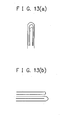
- the nanocarbon materials produced in the present invention include nanocarbon materials comprising aggregates of a plurality of worm-like shaped microunits; nanocarbon materials comprising aggregates of a plurality of filament-like shaped microunits; nanocarbon materials comprising aggregates of a plurality of coral-like shaped microunits; nanocarbon materials comprising aggregates of a plurality of rod-like shaped microunits each comprising spherical microparticles aggregated into an unit; and nanocarbon materials comprising aggregates of a plurality of tube-like shaped microunits, wherein the microunits in each case have an average diameter in a range of from 2 to 400 nm and an average length in a range of from 100 to 10000 nm, and the microunits in each case may have a transition metal element, a transition metal, a transition metal carbide, a transition metal oxide or
- nanocarbon materials produced in the present invention include nanocarbon materials having such a structure at molecular level as mentioned in the following which is identified in the observation by the TEM; a structure in that a plurality of graphene sheets (each comprising a single atomic layer of crystalline graphite) are stacked and developed into a fiber state, a structure in that a plurality of graphene sheets shaped in a cup-like form are stacked and developed into a filament-like state, or a structure in that a plurality of graphene sheets are connected with each other through their opposite ends into a tubular form.
- the method for producing nanocarbon materials of the present invention is characterized in that said method includes a step of contacting an aromatic compound-containing starting material with a supercritical fluid or a subcritical fluid in the presence of a transition metal element-containing catalyst at a temperature in a range of from 350 to 800 °C and at a pressure in a range of from 3 to 50 MPa.
- the supercritical fluid means a fluid having liquid properties and gaseous properties and which is in a state with a temperature and a pressure respectively exceeding the critical point (the critical temperature and the critical pressure) where gas and liquid can together exist.
- the subcritical fluid means a fluid following the supercritical fluid. Specifically, when the above critical temperature is made to be T 0 (absolute temperature) and the above critical pressure is made to be P 0 (MPa), the subcritical fluid means a fluid which is in a state with an absolute temperature T and a pressure P which satisfy the following equations. T ⁇ 0.8T 0 P ⁇ 0.8P 0
- the supercritical fluid or the subcritical fluid is formed from one or more raw materials selected from the group consisting of aromatic compounds as the starting material, a solvent for said aromatic compounds or the catalyst, water, dinitrogen monoxide, and ammonia.
- Said solvent for said aromatic compounds or the catalyst is preferred to comprise a solvent which can dissolve more than 2 mole% of a solute (that is, said aromatic compound or the catalyst) at a temperature of 20 °C under pressure of 0.1013 MPa, such as carbon dioxide, water, and alcohols.
- a solute that is, said aromatic compound or the catalyst
- These solvents may be used either singly or in combination of two or more of them.
- inert gas is introduced into the system where the starting material is contacted with the supercritical fluid or the subcritical fluid in the presence of the transition metal element-containing catalyst.
- the inert gas in this case can include argon gas, helium gas, and nitrogen gas. These gases may be used either singly or in combination of two or more of them as a mixed gas.
- the aromatic compound-containing starting material used in the present invention can include benzene, ethylbenzene, butylbenzene, toluene, xylene, styrene, biphenyl, phenylacetylene, phenol, ethylphenol, fluoranthene, pyrene, chrysene, phenanthrene, anthracene, naphthalene, methylnaphthalene, fluorene, biphenyl, acenaphthene, pitch, pitch coke, petroleum coke, and coal tar. These materials may be used either singly or in combination of two or more of them.
- the aromatic compound-containing starting material comprises an aromatic compound-containing starting material selected from the above-mentioned materials and which can be converted into a supercritical fluid or a subcritical fluid at a temperature in the foregoing temperature range of from 350 to 800 °C and at a pressure in the foregoing pressure range of from 3 to 50 MPa, it is not always necessary to use the raw material for forming the supercritical fluid or the subcritical fluid.
- the transition metal element of the transition metal element-containing catalyst is preferred to be a transition element selected from the group consisting of Ni, Co, Fe, Cu, Cr, W, Mo, Ti, Ru, Rh, Pd, and Ag.
- the transition metal element-containing catalyst may comprise at least one transition metal selected from the group consisting of transition metals of these transition metal elements or at least one transition metal compound selected from the group consisting of transition metal compounds of these transition metal elements.
- the transition metal compound can include transition metal sulfides, transition metal carbides, organo transition metal compounds, transition metal nitrides, transition metal oxides, and salts of transition metals. These transition metal compounds may be used either singly or in combination of two or more of them.
- the method of the present invention further include a step of subjecting the reaction product to a heat treatment at a temperature in a range of from 400 to 2800 °C, in order to remove impurities contained in the reaction product.
- a heat treatment at a temperature in a range of from 400 to 2800 °C
- the reaction product is subjected to a first heat treatment at a temperature in a range of from 400 to 900 °C, then, the reaction product is subjected to a second heat treatment at a temperature in a range of from 900 to 2800 °C.
- the heat treatment in the heat treating step is preferred to be performed in a gas atmosphere composed of one or more gases selected from the group consisting of argon gas, helium gas and nitrogen gas.
- the method of the present invention is preferred to include a purification step in that the heated-treated product is purified.
- the magnetic metal element-containing nanocarbon materials are collected by means of a magnet, whereby it is possible to obtain a purified nanocarbon materials-containing product.
- the nanocarbon materials contain a transition metal or a transition metal compound resulted from the catalyst and it is not necessary for the nanocarbon materials to contain such transition metal or such transition metal compound, it is possible to remove such transition metal or such transition metal compound therefrom by way of washing with an acid or the like.
- the present invention provides a method which enables one to quantitatively produce nanocarbon materials, characterized in that said method includes a step (a) of contacting an aromatic compound-containing starting material with a supercritical fluid or a subcritical fluid in the presence of a transition metal element-containing catalyst at a temperature in a range of from 350 to 800 °C and at a pressure in a range of from 3 MPa to 50 MPa.
- aromatic compound-containing starting material used in the present invention any aromatic compound-containing materials capable of producing nanocarbon materials and which can be acquired at a reasonable cost can be selectively used.
- aromatic compound-containing material there can be illustrated benzene, ethylbenzene, butylbenzene, toluene, xylene, styrene, biphenyl, phenylacetylene, phenol, ethylphenol, fluoranthene, pyrene, chrysene, phenanthrene, anthracene, naphthalene, methylnaphthalene, fluorene, acenaphthene, pitch, pitch coke, petroleum coke, and coal tar.
- aromatic compound-containing materials may be used either singly or in combination of two or more of them.
- benzene, toluene, naphthalene, methylnaphthalene, pitch, pitch coke, petroleum coke, and coal tar are preferred because they can be easily acquired at a relatively inexpensive cost.
- the supercritical fluid used in the present invention means a fluid having liquid properties and gaseous properties and which is in a state with a temperature and a pressure respectively exceeding the critical point (the critical temperature and the critical pressure) where gas and liquid can together exist.
- the subcritical fluid used in the present invention means a fluid following the supercritical fluid. Specifically, when the above critical temperature is made to be T 0 (absolute temperature) and the above critical pressure is made to be P 0 (MPa), the subcritical fluid means a fluid which is in a state with an absolute temperature T and a pressure P which satisfy the following equations. T ⁇ 0.8T 0 P ⁇ 0.8P 0
- the aromatic compound-containing starting material, a raw material for forming the supercritical fluid or the subcritical fluid and a given transition metal element-containing catalyst are introduced into a substantially enclosed reaction vessel, and the starting material, the raw material and the transition metal element-containing catalyst introduced in the reaction vessel are together heated at a prescribed temperature while being compressed at a prescribed pressure, where the raw material in a mixed state with the starting material and the catalyst is converted into a supercritical fluid or a subcritical fluid and the starting material is contacted with the resulting supercritical fluid or the resulting subcritical fluid and also with the catalyst to cause reaction of the stating material, whereby nanocarbon materials are synthesized.
- the heating temperature and the compressing pressure in this case are somewhat different depending upon the kind of the raw material used for forming the supercritical fluid or the subcritical fluid. However, in general, it is preferred that the heating temperature is in a range of from 350 °C to 800 °C and the compressing pressure is in a range of from 3 MPa to 50 MPa and it is more preferred that the heating temperature is in a range of from 400 °C to 600 °C and the compressing pressure is in a range of from 4 MPa to 30 MPa, from the viewpoint of the condition under which nanocarbon materials are produced and also from the viewpoints of diminishing the cost of the apparatus used and saving the operation energy.
- the raw material for forming the supercritical fluid or the subcritical fluid is required to comprise a fluid material which can serve as a solvent for the starting material or as a solvent for the catalyst.
- the supercritical fluid or the subcritical fluid formed from the raw material for forming the supercritical fluid or the subcritical fluid functions as a medium (a reaction promotion medium) to promote the formation of nonacarbon materials from the aromatic compound-containing starting material.
- the foregoing heating temperature and the foregoing compressing pressure respectively exceed the critical temperature and the critical pressure of the supercritical fluid or the subcritcal fluid.
- the starting material In the case where the aromatic compound-containing starting material itself is situated in the supercritical fluid or the subcritical fluid, the starting material is in a very active state such that the reaction of the starting material will readily occur.
- the raw material which is converted into the supercritical fluid or the subcritical fluid comprises a raw material capable of being converted into a supercritical fluid or a subcritical fluid at a temperature in a range of from 350 °C to 800 °C and at a pressure in a range of from 3 MPa to 50 MPa.
- Such raw material can include a solvent for aromatic compounds as the starting material, a solvent for the catalyst, dinitrogen monoxide, and ammonia.
- Said solvent is preferred to comprise a solvent which can dissolve more than 2 mole% of a solute (that is, said aromatic compound or the catalyst) at a temperature of 20 °C under pressure of 0.1013 MPa.
- the starting material comprises an aromatic compound-containing material selected from the previously illustrated materials as the starting material and which can converted into a supercritical fluid or a subcritical fluid at a temperature which falls in the above temperature range of from 350 °C to 800 °C and at a pressure which falls in the above pressure range of from 3 MPa to 50 MPa, it is not always necessary to introduce the raw material for forming the supercritical fluid or the subcritical fluid into the reaction vessel.
- a given aromatic compound which can converted into a supercritical fluid or a subcritical fluid at a temperature in a range of from 350 °C to 800 °C and at a pressure in a range of from 3 MPa to 50 MPa as the starting material is more preferred for the reason that said aromatic compound as the starting material becomes to be very active so that the reaction thereof more readily proceeds under condition with said temperature and said pressure.
- the transition metal element-containing catalyst used in the method of the present invention comprises particles of a given transition metal element-containing material. Therefore, the sizes of nanocarbon materials synthesized are quite liable to greatly depend on the particle sizes of the catalyst particles.
- fine particles of the transition metalelement-containing material are used as the transition metal element-containing catalyst and the catalyst fine particles are sufficiently contacted with the starting material such that each of the catalyst fine particles is contacted with the starting material.
- the solvent capable of dissolving the aromatic compound-containing starting material or/and the catalyst (the catalyst fine particles) is mixed with the starting material and the catalyst.
- a surface-active agent to the solvent.
- the solvent for aromatic compound as the starting material or the catalyst there can be illustrated carbon dioxide, water, alcohols, and ethers. These solvents may be used either singly or in combination of two or more of them as a mixed solvent.
- the alcohol there can be illustrated methanol, ethanol, and propyl alcohol.
- carbon dioxide is the most appropriate for the reasons that besides functioning as the solvent, carbon dioxide itself is poor in terms of the reactivity and because of this, it is presumed that carbon dioxide will function to reduce the probability for the molecules of the starting material to be mutually collided and prevent side reactions from being occurred.
- the critical temperature and the critical pressure at which carbon dioxide is converted into a supercritical fluid are respectively 31 °C and 7.38 MPa.
- the critical temperature and the critical pressure at which water is converted into a supercritical fluid are respectively 374 °C and 22.0 MPa.
- the critical temperature and the critical pressure at which toluene is converted into a supercritical fluid are respectively 318 °C and 4.11 MPa.
- the critical temperature and the critical pressure at which naphthalene is converted into a supercritical fluid are respectively 475 °C and 4.11 MPa.
- inert gas it is preferred to introduce inert gas into the system where the aromatic compound-containing starting material is contacted with the supercritical fluid or the subcritcal fluid in the presence of the transition metal element-containing catalyst, in order to synthesize nanocarbon materials at a high purity while reducing the probability for the molecules of the starting material to be mutually collided and preventing side reactions from being occurred.
- inert gas argon gas, helium gas, or nitrogen gas may be used.
- the transition metal element of the transition element-containing catalyst used in the method of the present invention can include Ti, V, Cr, Mn, Fe, Co, Ni, Cu, Y, Zr, Nb, Mo, Ru, Rh, Pd, Ag, Ta, W, Pt, and Au.
- Ni, Co, Fe, Cu, Cr, W, Mo, Ti, V, Mn, Ru, Rh, Pd, and Ag are more preferred, and Ni, Co, Fe, Cu, Cr, W, Mo, and Ti are most preferred.
- the transition metal element-containing catalyst may comprise at least one transition metal selected from the group consisting of transition metals of these transition metal elements or at least one transition metal compound selected from the group consisting of transition metal compounds of these transition metal elements.
- aforesaid transition metal or aforesaid transition metal compound as the transition metal element-containing catalyst is introduced into the reaction vessel together with the aromatic compound-containing starting material and the raw material for forming the supercritical fluid or the subcritical fluid. And in the reaction vessel, when the raw material is converted into the supercritical fluid or the subcritical fluid while being contacted with the starting material, the transition metal or the transition metal compound is present in contact with the starting material and the supercritical fluid or the subcritical fluid, where the transition metal or the transition metal compound functions as a starting point to initiate formation of nanocarbon materials from the stating material in contact with the supercritical fluid or the subcritical fluid and the nanocarbon materials thus started forming are gradually grown. In this case, it is considered that the transition metal or the transition metal compound behaves like a catalyst.
- the transition metal or the transition metal compound is not always necessary to be externally added.
- the transition metal or the transition metal compound may be one originally contained in the starting material or one resulted when the starting material is contacted with the supercritical fluid or the subcritical fluid.
- transition metal compound there can be illustrated transition metal sulfides, transition metal carbides, organo transition metal compounds, transition metal nitrides, transition metal oxides, and salts of transition metal (hereinafter referred to as transition metal salts).
- transition metal salts are more preferable for the following reason.
- the transition metal salt is reduced or oxidized into a transition metal or a transition metal oxide in the reaction to afford nanocabon materials in the method of the present invention. It is possible that said transition metal or said transition metal oxide is dissolved in an acid to recover as a transition metal salt.
- the recovered transition metal salt can be reused as the catalyst.
- transition metal sulfide there can illustrated nickel sulfide, iron sulfide, cobalt sulfide, copper sulfide, titanium sulfide, tungsten sulfide, and molybdenum sulfide.
- transition metal carbide As preferable specific examples of aforesaid transition metal carbide, there can be illustrated tungsten carbide, molybdenum carbide, and titanium carbide.
- organo transition metal compound there can be illustrated ferrocene, nickelocene, nickel formate, nickel oxalate, nickel naphthenate, nickel phthalocyanine, cobalt phthalocyanine, copper phthalocyanine, nickel acetylacetonato, cobalt acetylacetonato, iron acetylacetonato, copper acetylacetonato, nickel carbonyl, cobalt carbonyl, iron carbonyl, bis(triphenylphosphine)dicarbonylnickel, dibromobis(triphenylphosphine)nickel, and chlorotris(triphenylphosphine)rhodium.
- the transition metal or transition metal compound which is used as the transition metal element-containing catalyst in the method of the present invention particles (fine particles) thereof are used as previously described.
- the average diameter of microunits (observed in the observation by the electron microscope) which constitute nanocarbon materials produced according to the method of the present invention depends on the average particle size of the catalyst particles, it is important to properly control the average particle size of the catalyst particles.
- the catalyst particles are used by dispersing them in a retaining body so as to retain them on the retaining body or a manner in that in addition to the catalyst particles, a solvent capable of dissolving them is introduced or a surface-active agent capable of preventing them from being aggregated is introduced.
- sulfur or/and a sulfur compound are made to exist together with the transition metal or the transition metal compound as the transition metal element-containing catalyst in the system where the aromatic compound-containing material is contacted with the supercritical fluid or the subcritical fluid.
- the presence of said sulfur or/and said sulfur compound occasionally serves to control the direction for the nanocarbon materials to be grown.
- the sulfur compound can include thiol, thioacetamide, thionaphthene, thiosemicarbazido, thiourea, and thiophene. Of these, thiol is particularly preferable.
- thiol there can be illustrated 1-octanethiol(n-octylmercaptan), 1-decanethiol (n-decylmercaptan), 1-dodecanethiol (n-dodecylmercaptan), n-butylmercaptan, propylmercaptan, methylmercaptan, ethylmercaptan, benzylmercaptan, and thiophenol.
- the sulfur or the sulfur compound is not always necessary to be externally added.
- the sulfur or the sulfur compound may be one originally contained in the starting material.
- pitch, pitch coke, petroleum coke and coal tar which are mentioned in the above as examples of the aromatic compound-containing starting material often contain sulfur or/and sulfur compound therein.
- Such sulfur or/and such sulfur compound contained in the starting material may be used instead of the sulfur or/and the sulfur compound which are externally added.
- the method of the present invention is preferred to include a heat-treating step (b).
- the heat-treating step (b) the reaction product obtained in the step (a) wherein the aromatic compound-containing starting material is contacted with the supercritical fluid or the subcritical fluid in the presence of the transition metal element-containing catalyst at a temperature in a range of from 350 to 600 °C is subjected to a heat treatment to remove impurities including unreacted material contained in the reaction product.
- the reaction product obtained in the step (a) contains nanocarbon materials synthesized in the step (a).
- the heat-treating step (b) serves to improve the purity of the nanocarbon materials contained in the reaction product by removing the impurities therefrom and it also serves to further develop the graphene sheet structures of the nanocarbon materials.
- reaction product prior to subjecting to the heat treatment or the heat-treated reaction product obtained in the heat-treating step is washed with an acid or the like to remove the catalyst (the catalyst particles) therefrom.
- the heat treatment of the reaction product in the heat-treating step (b) is preferred to perform at a temperature in a range of from 400 to 2800 °C.
- the heat treatment of the reaction product in the heat-treating step (b) is preferred to perform in a gas atmosphere composed of inert gas.
- the inert gas can include argon gas, helium gas and nitrogen gas. These gases may be used either singly or in combination of two or more of them as a mixed gas.
- the heat treatment of the reaction product is repeated several times by changing the heat-treating temperature, for instance, in such a manner that the reaction product is subjected to a first heat treatment at a temperature in a low temperature side region of the above-described temperature region, followed by subjecting to a second heat treatment at a temperature in a middle to high temperature side region of the above-described temperature region.
- the reaction product is subjected to a first heat treatment at a relatively low temperature in a range of from 400 to 800 °C, followed by subjecting to a second heat treatment at a high temperature in a range of from 900 to 2800 °C end it is more preferred that the reaction product is subjected to a first heat treatment at a relatively low temperature in a range of from 400 to 800 °C, followed by subjecting to a second heat treatment at a high temperature in a range of from 1000 to 2400 °C.
- the heat treatment of the reaction product at a temperature in a region of from 2400 to 2800 °C is liable to develop the graphite structures(comprising a plurality of graphene sheets stacked) of the nanocarbon materials contained therein.
- nanocarbon materials synthesized according to the method of the present invention are different with respect to their constituent microunits observed by SEM (scanning electron microscope) depending on the kind of the aromatic compound-containing starting material, the kind of the transition metal element-containing catalyst, the kind of the raw material for forming the supercritical fluid or the subcritical fluid, the reaction temperature and the reaction pressure.
- nanocarbon materials comprising aggregates of a plurality of worm-like shaped microunits; nanocarbon materials comprising aggregates of a plurality of filament-like shaped microunits; nanocarbon materials comprising aggregates of a plurality of coral-like shaped microunits; nanocarbon materials comprising aggregates of a plurality of rod-like shapedmicrounits each comprising spherical microparticles aggregated into an unit; and nanocarbon materials comprising aggregates of a plurality of tube-like shaped microunits, wherein the microunits in each case have an average diameter in a range of from 2 to 400 nm and an average length in a range of from 100 to 10000 nm.
- nanocarbon materials comprising aggregates of a plurality of worm-like shaped microunits having an average diameter of 10 nm to 50 nm can be readily synthesized at a more high purity.
- those nanocarbon materials mentioned in the above include (a) nanocarbon materials having a microstruture in which a layered structure comprising a plurality of graphene sheets stacked is developed into a cylindrical structure having a diameter of 20 nm to 400 nm; (b) nanocarbon materials having a microstructure in which a plurality of cup-like shaped graphene sheets are gathered and developed into a stacked structure having a diameter of 10 nm to 50 nm; (c) nanocarbon materials having a microstructure in which the graphene sheet is rolled up into a single-layered cylindrical structure or a multi-layered cylindrical structure, respectively having a diameter of 0.4 nm to 10 nm; and (d) nanocarbon materials having a microstructure in which a graphene sheet is developed into a layered state whose end portion is closed, said closed end portion having a length of 0.4 nm to 5 nm.
- TEM transmission electron microscope
- nanocarbon materials whose worm-like shaped microunits having an average diameter of 10 nm to 50 nm and can be readily synthesized according to the method of the present invention
- nanocarbon materials having such microstructure as described in the above (a) or (b) can be readily synthesized at a high purity and at a high yield.
- the synthesized nanocarbon materials contain a transition metal or a transition metal compound resulted from the catalyst at their tip portions in may cases.
- Such transition metal or such transition compound can be removed by dissolving it with an acid or the like.
- the method of the present invention is preferred to a purification step (c) after the heat-treating step (b).
- the resulting nanocarbon materials-containing product contains nanocarbon materials containing a magnetic body.
- the product is heat-treated in the heat-treating step (b) in the manner as previously described.
- the purification step (c) comprises subjecting the heat-treated product to a purification treatment of collecting only the magnetic body-containing nanocarbon materials by means of a magnet such as a permanent magnet or an electromagnet to obtain a purified nanocarbon materials-containing product.
- said heat-treated product is dispersed in a dispersion medium such as alcohol or water while irradiating ultrasonic wave, and thereafter, the magnetic body-containing nanocarbon materials are collected by means of a permanent magnet or an electromagnet, whereby it is possible to obtain a purified nanocarbon materials-containing product.
- the nanocarbon materials contained in the product contain the magnetic body.
- the product it is possible to subject the product to a further purification treatment in that the product is treated with an acid (such as nitric acid, hydrochloric acid, sulfuric acid, or hydrofluoric acid) or an alkali (such as sodium hydroxide or potassium hydroxide) to dissolve and remove the magnetic body contained in the nanocarbon materials contained in the product and the product thus treated is washed and dried.
- an acid such as nitric acid, hydrochloric acid, sulfuric acid, or hydrofluoric acid
- an alkali such as sodium hydroxide or potassium hydroxide
- the purification step (C) may be performed in the following manner.
- the product is treated with an acid (such as nitric acid, hydrochloric acid, sulfuric acid, or hydrofluoric acid) or an alkali (such as sodium hydroxide or potassium hydroxide) to dissolve and remove the transition metal or the transition metal compound contained in the nanocarbon materials contained in the product and the product thus treated is washed and dried.
- an acid such as nitric acid, hydrochloric acid, sulfuric acid, or hydrofluoric acid
- an alkali such as sodium hydroxide or potassium hydroxide
- the nanocarbon materials obtained to contain such residue resulted from the catalyst in their microunits or in their tip portions, depending on the application use.
- the purification by means of said acid or said alkali is not necessary to be performed.
- said purification is performed in the case where the nanocabon materials are adopted in the application use where said residue contained in the nanocarbon materials is liable to provide adverse effects.
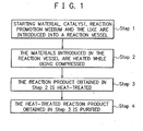
- FIG. 1 shows a flow chart illustrating an example of the above-described method of the present invention.
- FIG. 7 is a schematic cross-sectional view illustrating an example of a reaction apparatus used for practicing the method of the present invention.
- Step 1 a given aromatic compound-containing starting material, a given transition metal element-containing catalyst, and if necessary, a given reaction promotion medium (comprising a solvent for said starting material and a solvent for said catalyst) for promoting the reaction of said starting material and given inert gas are introduced into a substantially enclosed reaction vessel of a reaction apparatus.
- a given reaction promotion medium comprising a solvent for said starting material and a solvent for said catalyst
- Step 2 the materials introduced in the reaction vessel are together heated at a temperature in a range of from 350 °C to 800 °C while being compressed at a pressure in a range of from 3 MPa to 50 MPa, where the starting material and/or the reaction promotion medium is converted into a supercritical fluid or a subcritical fluid and the starting material is contacted with the supercritical fluid or the subcritical fluid in the presence of the catalyst to obtain a nanocarbon materials-containing reaction product.
- Step 3 the reaction product obtained in Step 2 is subjected to a heat treatment at a temperature of 400 °C to 2800 °C preferably in an inert gas atmosphere mainly in order to remove impurities contained in the reaction product.
- Step 4 the heat-treated reaction product obtained in Step 3 is subjected to a purification treatment by means of a magnet or by means of an acid or an alkali.
- the reaction apparatus shown in FIG. 7 comprises a substantially enclosed pressure reaction vessel 702 provided with a pressure gauge 703, a heater 704, and a safety vent 705. At least the inner wall of the reaction vessel 702 is made of preferably a stainless steel or more preferably a Ni-Mo alloy so as to have sufficient corrosion resistance.
- Reference numeral 701 indicates a material comprising the foregoing reaction promotion medium and the foregoing transition metal element-containing catalyst which is contained in the reaction vessel 702, and reference numeral 700 indicates the foregoing aromatic compound-containing starting material mixed in the material 701 in the reaction vessel 702.
- the reaction apparatus is provided with an agitation mechanism in order to uniformly promote the reaction in the reaction vessel.
- the reaction apparatus is preferred to have a circulating flow reaction system in that from the reaction product containing nanocarbon materials and unreacted starting material which is outputted from the reaction vessel, a nanocarbon materials-containing reaction product is isolated and the unreacted starting material is returned into the reaction vessel, in order to improve the yield from the starting material.
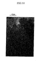
- the form of a nanocarbon material synthesized in the present invention can be identified by way of observation by means of a scanning electron microscope (SEM), and the microstructure of said nanocarbon material can be identified by way of observation by means of a transmission electron microscope (TEM).
- SEM scanning electron microscope
- TEM transmission electron microscope
- the proportion of an amorphous component contained in the nanocarbon material may be analyzed by means of X-ray diffraction analysis or laser Raman spectroscopy.
- a nanocarbon material synthesized in the present invention contains a carbon nanotube
- Raman spectrum of said carbon nanotube there are observed a Raman line at a position in the vicinity of 1528 to 1606 cm -1 , a Raman line at a position in the vicinity of 1353 cm -1 , and a Raman line at a position in the vicinity of 2700 cm -1 .
- a nonocarbon material synthesized in the present invention is identified whether or not the graphene sheet in the microstructure is developed such that it is rolled up into a single-layered cylindrical structure or a multi-layered cylindrical structure
- a sharp X-ray diffraction peak is observed in the X-ray diffraction pattern
- the graphene sheet is developed as above described and thus the purity of the nanocarbon material is high
- a broad X-ray diffraction peak is observed in the X-ray diffraction pattern
- the graphene sheet is not developed and the nanocarbon material contains an amorphous carbon component.
- the nanocarbon material contains an amorphous carbon component in a large amount, a strong peak is observed at a position in the vicinity of 1353 cm -1 in the Raman spectrum.
- the purity of the nanocarbon material can be evaluated by way of identification of the form thereof by means of SEM. It can be also evaluated by TEM observation, or the half band width of the X-ray diffraction peak. Besides, it can be evaluated based on the ratio of a peak intensity in the vicinity of 1353 cm -1 to a peak intensity in the vicinity of 1528 to 1606 cm -1 in the Raman spectrum.
- a cell is prepared by arranging a working electrode comprising said nanocarbon materials-containing product and a counter electrode comprising a lithium metal in an electrolyte solution comprising a lithium salt as an electrolyte dissolved in a nonaqueous solvent such that said working electrode and said counter electrode are opposed to each other. Then, lithium is electrochemically inserted in the working electrode and the lithium is electrochemically released from the working electrode, where the electricity quantity consumed upon the insertion of the lithium is compared with the electricity consumed upon the release of the lithium.
- Evaluation with respect to the performance of a nanocarbon materials-containing product obtained in the present invention when it is used as a cathode for a field emission display (FED) may be performed, for instance, in the following manner.
- a prescribed electric field is applied between a cathode comprising said nanocarbon materials-containing product and an anode as the counter electrode to said cathode under reduced pressure, where the value of an electric current flown per a unit area of the cathode is measured.
- Evaluation with respect to the hydrogen storage ability of a nanocarbon materials-containing product obtained in the present invention to store hydrogen therein may be performed, for instance, in the following manner.
- Said nanocarbon materials-containing product is maintained in a hydrogen gas under low temperature condition to permeate hydrogen gas in the nanocarbon materials-containing product and thereafter, the nanocarbon materials-containing product is heated to release hydrogen from the product, where the amount of the permeated hydrogen and the amount of the released hydrogen are measured. Based on the measured results, the stored hydrogen amount per a unit weight of the product is computed. When said amount is large, it means that the nanocarbon materials-containing product is good enough in the hydrogen storage ability.
- the specific surface area and the electron conductivity of the nanocarbon materials-containing product are important factors. Therefore, said specific surface area and said electron conductivity are measured. Besides, the average particle size of catalyst particles of Pt or the like which are retained in the nanocarbon materials-containing product and the power output characteristics of a fuel cell in which a catalyst-retaining layer comprising the nanocarbon materials-containing product having catalyst particles of Pt or the like retained therein is used are evaluated. In this case, it is better that the specific surface area is high, the resistivity is small, and the average particle size of the catalyst particles which are retained is small. When the resistivity is small, the electron conductivity is increased and the electrode resistance is decreased, and a result, the power outputted is increased.
- nanocarbon product a nanocarbon materials-containing product obtained in the present invention (this nanocarbon materials-containing product will be hereinafter referred to as "nanocarbon product”) is low in terms of the resistivity and high in terms of the specific surface area.
- a catalyst layer on the surface of an electrode of a fuel cell is formed of a carbon black having (a) catalyst particles of Pt or the like (whose particle sizes are relatively large) retained thereon.
- the nanocarbon product has a specific surface area which is larger than that of the carbon black.
- the specific surface area per a unit weight of the catalyst particles (b) is quite large.
- the latter is superior to the former in terms of the performance as the catalyst.
- the purpose can be achieved by using the catalyst particles (b) in a smaller amount (in terms of weight) than that of the catalyst particles (a).
- the cost of the fuel cell can be diminished.
- the resistivity of the nanocarbon product is smaller than that of the carbon black and the nanocarbon product has a high electron conductivity. Therefore, the use of the nanocarbon product instead of the carbon black enables to improve the power generation efficiency of the fuel cell.
- a nanocarbon materials-containing product obtained in the present invention can be desirably used, for instance, as a negative electrode material of a rechargeable lithium battery, as a cathode material of a FED, and as a hydrogen storage material of a hydrogen storage system.
- nanocarbon material a nanocarbon materials-containing product obtained in the present invention in such applications.
- the nanocarbon material is used in a rechargeable lithium battery (here, this includes a rechargeable lithium ion battery), it is preferred to be used as the anode material.
- FIG. 2 is a schematic cross-sectional view illustrating the constitution of an example of a rechargeable lithium battery.
- reference numeral 201 indicates an anode
- reference numeral 202 an ion conductor
- reference numeral 203 a cathode
- reference numeral 204 an anode terminal
- reference numeral 205 a cathode terminal
- reference numeral 206 a battery housing.
- the anode 201 in the rechargeable lithium battery shown in FIG. 2 comprises an electrode structural body 305 shown in FIG. 3.
- reference numeral 300 indicate a collector, reference numeral 301 a nanocarbon material in a powdery form (obtained in the present invention), reference numeral 302 a binder, reference numeral 303 an electrically conductive auxiliary, and reference numeral 304 an active material layer.
- the electrode structural body 305 shown in FIG. 3 may be prepared, for instance, in the following manner.
- a binder 302 comprising an organic polymer is admixed with aforesaid powdery nanocarbon material 301, and if necessary, an electrically conductive auxiliary 303 and a solvent are added, to obtain a mixture.
- the mixture is disposed on a collector 300 comprising a copper foil or the like to form an active material layer 304 on the collector 300, whereby an electrode structural body 305 is obtained.
- the resultant electrode structural body 305 is used as the anode 201 in the rechargeable lithium battery shown in FIG. 2.
- organic polymer used as the binder 302 it is possible to use a fluororesin such as polyvinylidene fluoride or the like or a water-soluble organic polymer such as polyvinyl alcohol or the like.
- a powder of a lithium-transition metal oxide, a lithium-transition metal phosphate, or a lithium-transition metal sulfate, an electrically conductive auxiliary comprising a graphite powder or the like, a binder comprising an organic polymer, and a solvent are mixed to obtain a mixture.
- the mixture is disposed on a collector comprising an aluminum foil or the like to form a cathode active material layer on the collector, whereby an electrode structural body is obtained.
- the resultant electrode structural body is used as the cathode 203.
- the transition metal element of the lithium-transition metal oxide, the lithium-transition metal phosphate or lithium-transition metal sulfate which is used as the cathode active material may be Co, Ni, Mn, or Fe.
- organic polymer used as the binder it is possible to use a fluororesin such as polyvinylidene fluoride or the like or a water-soluble organic polymer such as polyvinyl alcohol or the like.
- a separator comprising a microporous polyolefin series film formed of polyethylene or polypropylene having an electrolyte retained therein.
- the electrolyte may be an electrolyte solution obtained by dissolving a lithium salt selected from lithium salts of Li + (lithium ion) with Lewis acid ions such as BF 4 - , PF 6 - , AsF 6 - , ClO 4 - , CF 3 SO 3 - , N(CF 3 SO 2 ) 2 - , or BPh 4 - (with Ph being a phenyl group) in an organic solvent such as ethylene carbonate, propylene carbonate, dimethyl carbonate, or diethyl carbonate, or a gelated electrolyte obtain by gelating said electrolyte solution by adding an organic polymer thereto.
- a lithium salt selected from lithium salts of Li + (lithium ion) with Lewis acid ions such as BF 4 - , PF 6 - , AsF 6 - , ClO 4 - , CF 3 SO 3 - , N(CF 3 SO 2 ) 2 - , or BPh 4
- FIG. 4 is a schematic cross-sectional view illustrating the constitution of an example of a FED.
- reference numeral 400 indicates an insulating plate (a glass plate), reference numeral 401 a back electrode (a negative electrode), reference numeral 402 a cathode layer formed using a nanocarbon material in a powdery form (obtained in the present invention), reference numeral 403 an insulating spacer (a barrier wall), reference numeral 404 a fluorescent substance layer, reference numeral 405 a transparent electrode (an anode), reference numeral 406 a surface mask, reference numeral 407 a transparent surface member, and reference numeral 408 an inside space.
- the FED shown in FIG. 4 may be prepared, for instance, in the following manner.
- a metal electrode pattern 401 is arranged on a glass plate 400.
- a paste obtained by mixing aforesaid powdery nanocarbon material with a binder to obtain a mixture and adding a solvent to said mixture is coated by means of screen-printing or the like, followed by drying and baking to form a layer as the cathode layer 402.
- a transparent electrode pattern 405 is formed on a glass plate 407 and on the transparent electrode pattern 405, there is formed a fluorescent substance layer 404 by means of screen-printing or the like.
- the transparent electrode 405 (the anode) and the cathode layer 402 are opposed to each other, and a spacer 403 (a barrier wall) is arranged between the transparent electrode 405 and the cathode layer 402. After the inside space 408 of the system is evacuated to a prescribed vacuum, the system is closed. In this way, the FED shown in FIG. 4 may be prepared.
- the I-V characteristics with respect to electron emission from a nanocarbon material obtained in the present invention may be evaluated, for instance, in the following manner.
- FIG. 5 is a schematic cross-sectional view illustrating the constitution of an example of an element used for evaluating the electron emission performance of said nanocarbon material.
- reference numeral 500 indicates an insulating substrate, reference numeral 501 an electrode pattern, reference numeral 502 a cathode formed using said nanocarbon material, reference numeral 503 an insulating spacer, reference numeral 504 an anode, reference numeral 505 a cathode terminal, and reference numeral 506 an anode terminal.
- the element shown in FIG. 5 is placed in a vacuum chamber provided with a current introduction terminal, where the I-V characteristics with respect to electron emission from the nanocarbon material may be evaluated by applying a prescribed voltage between the anode 504 and the cathode 502 (comprising the nanocarbon material) and measuring the value of an electric current flown between the cathode 502 and the anode 504.
- the element shown in FIG. 5 may be prepared, for instance, in the following manner.
- a mask having a cathode pattern with an electrode-drawing portion formed by way of etching is close-contacted onto a sodium-free glass substrate 500 (comprising, for instance, a No. 7059 glass plate produced by Corning Company), and thereafter, a 50 nm thick Cr film, a 300 nm thick Al film and a 50 nm thick Cr film are sequentially deposited by means of electron beam evaporation or the like to form an electrode pattern 501.
- the foregoing powdery nanocarbon material is dispersed in isopropyl alcohol while irradiating ultrasonic wave, and said electrode pattern and a counter electrode are immersed in the dispersion, where a D.C. electric field is applied between the electrode pattern and the counter electrode to deposit said nanocarbon material on the electrode pattern 501 to form a cathode layer as the cathode 502.
- an insulating member comprising a mica and having a thickness of about 20 ⁇ m as the insulating spacer 503 is fixed on the cathode 502, and thereon, an aluminum plate as the anode 504 is fixed.
- a cathode terminal 505 is connected to the electrode pattern 501
- an anode terminal 506 is connected to the aluminum plate as the anode 504. In this way, the element shown in FIG. 5 may be prepared.
- the evaluation of the I-V characteristics with respect to electron emission of the nanocarbon material by using the element shown in FIG. 5 may be performed in the following manner.
- the element is placed in a vacuum chamber provided with a current introduction terminal and which is preferably maintained at a vacuum of less than 10 -3 Pa, where a prescribed voltage is applied between the anode 504 and the cathode 502 (comprising the nanocarbon material) and the value of an electric current flown between the cathode 502 and the anode 504 is measured, wherein based on the interrelation between the values of the flown electric current and the values of the voltage applied, the I-V characteristics of the nanocarbon material are evaluated.
- the hydrogen-storing performance of a nanocarbon material produced in the present invention may be evaluated by using a measuring apparatus shown in FIG. 6 having a container with a prescribed volume in which said nanocarbon material is charged and a vessel in which hydrogen is stored, wherein said container and said vessel are connected through a switching valve.
- a measuring apparatus shown in FIG. 6 having a container with a prescribed volume in which said nanocarbon material is charged and a vessel in which hydrogen is stored, wherein said container and said vessel are connected through a switching valve.
- reference numeral 600 indicates a high pressure hydrogen gas cylinder, reference numeral 601 a vessel in which hydrogen is stored, reference numeral 602 a container in which the nanocarbon material is charged, reference numeral 603 a temperature controller, reference numeral 604 a vacuum pump, reference numeral 605 a pressure gage, reference numeral 606 a vacuum gage, reference numeral 607 a pressure regulation valve, and each of reference numerals 608, 609, 610, 611, 612, and 613 a switching valve.
- the vacuum gage 601 is connected to the container 602 through the switching valves 611, 612 and 613.
- the vacuum pump 604 is connected to the container 602 through the switching valves 611 and 612.
- the pressure gage 605 is connected to the vessel 601 through the switching valve 609.
- the hydrogen gas cylinder 600 is connected to the vessel 601 through the switching valve 608 and the pressure regulating valve 607.
- the evaluation of the hydrogen-storing performance of the nanocarbon material by using the measuring apparatus shown in FIG. 6 may be performed, for instance, in the following manner.
- a sufficiently dried powdery nanocarbon material is provided.
- the weight of the powdery nanocarbon material is measured, and the powdery nanocarbon material is inserted in the container 602.
- the inside of the container 602 is evacuated to a high vacuum, and hydrogen gas from the vessel 601 whose inside pressure is maintained at a prescribed pressure is introduced into the container 602 by opening the switching valves 610 and 611, and after a prescribed period of time is elapsed, the hydrogen gas pressure in the container 602 and that in the vessel 601 are measured. From the initial hydrogen gas pressure in the vessel 601, the volume of the vessel 601 and that of the container 602, it is possible to compute the amount of hydrogen stored in the powdery nanocarbon material per a unit weight of the powdery nanocarbon material.
- the stored hydrogen amount and the released hydrogen amount respectively when the hydrogen gas pressure in the container 602 is equilibrated are measured, and based on the measured results, the hydrogen stored amount per a unit weight of the powdery nanocarbon material is computed.
- reaction vessel made of a Hastelloy (comprising a Ni-Mo alloy)(trademark name, produced by Haynes International Inc.)] with an inner volume of 96 ml of the reaction apparatus shown in FIG. 7, 2.5 g of toluene (the critical temperature: 319 °C ; the critical pressure: 4.11 MPa) as the starting material and 0.2 g of a nickelocene (bis(cyclopentadienyl)nickel) as the transition metal element-containing catalyst were introduced and they were mixed, followed by adding 30g of dryice (as the raw material for forming the supercritical fluid or the subcritical fluid) thereto, and the reaction vessel was closed.
- toluene the critical temperature: 319 °C ; the critical pressure: 4.11 MPa
- nickelocene bis(cyclopentadienyl)nickel
- nanocarbon product (a) The yield of the nanocarbon product (a) produced in this case was calculated.
- the dryice introduced in the reaction vessel is vaporized into CO 2 gas. Therefore, the adjustment of the reaction pressure to a prescribed value (12.0 MPa) was conducted by exhausting part of the CO 2 gas outside the reaction vessel.
- a temperature-pressure curve with respect to the relationship between the gaseous pressure in the reaction vessel before heated and an increase in the gaseous pressure along an increase in the inside temperature of the reaction vessel has been established in advance. In accordance with the temperature-pressure curve, by exhausting part of the CO 2 gas outside the reaction vessel before heated, the adjustment of the reaction pressure was conducted.
- the pressure adjustment is conducted under temperature condition of the temperature of the dryice, the vapor pressure of an aromatic compound such as toluene or the like as the starting material is extremely low and therefore, the amount of the gas vaporized from the starting material which is exhausted outside the reaction vessel is very small to such an extent that can be disregarded.
- a part of the resultant nanocarbon product (a) was subjected to a heat treatment at a temperature of 1500 °C for 2 hours to obtain a powdery nanocarbon materials-containing product (this will be hereinafter referred to as "heat-treated nanocarbon product (b)").
- Each of a sample of the nanocarbon product (a) and a sample of the heat-treated nanocarbon product (b) was subjected to observation by means of a SEM (scanning electron microscope) and a TEM (transmission electron microscope).
- SEM scanning electron microscope
- TEM transmission electron microscope
- each of them was subjected to measurement with respect to specific surface area by means of the BET (Brunauer-Emmet-Teller) method.
- BET Brunauer-Emmet-Teller
- Each of the nanocarbon product (a) and the heat-treated nanocarbon product (b) comprises an enormous number of worm-like shaped microunits which are substantially uniform as shown in a SEM image of FIG. 8.
- the worm-like shaped microunits of the nanocarbon product (a) are substantially the same as those of the heat-treated nanocarbon product (b).
- the worm-like shaped microunits of each of the nanocarbon product (a) and the heat-treated nanocarbon product (b) have an average diameter of 20 to 30 nm and an average length of 200 to 500 nm and they contain nickel metal microparticles at their tips.
- FIG. 11(a) is a schematic view showing one of said worm-like shaped microunits which contains a nickel metal microparticle at the tip thereof.
- FIG. 9 shows a TEM image of the heat-treated nanocarbon product (b) in which a black region corresponds to a nickel metal microparticle.
- the heat-treated nanocarbon product (b) was treated with hydrochloric acid then treated with nitric acid to elute and remove the nickel contained therein.
- the heat-treated nanocarbon product (b) thus treated was washed with ion-exchanged water and heat-treated at a temperature of 350 °C in an air atmosphere, whereby a powdery Ni-free nanocarbon product [hereinafter referred to as "nanocarbon product (b')] was obtained.
- the nanocarbon product (b') was subjected to evaluation with respect to the electron emission performance. Particularly, an element having the structure shown in FIG. 5 was prepared in the previously described manner for the preparation of the element shown in FIG. 5 wherein using the nanocarbon product (b'), a nanocarbon material layer as the cathode 502 was formed on the electrode pattern 501 by way of electro-deposition.
- the element thus prepared was placed in a vacuum chamber provided with a current introduction terminal and which is maintained at a vacuum of less than 10 -3 Pa, where a prescribed electric field was impressed to the element to measure I-V characteristics with respect to electron emission.
- the nanocarbon product (b') [corresponding to the heat-treated nanocarbon product (b)] was found to have an electron emission performance which is greater by about 10 times that of a commercially available carbon multinanotube material (produced by The Honjo Chemical Corporation).
- the nanocarbon product (a) was subjected to evaluation with respect the hydrogen-storing ability thereof in accordance with the previously described evaluation manner using the measuring apparatus shown in FIG. 6. As a result, the nanocarbon product (a) was found to have a hydrogen-storing ability which is substantially the same as that of a commercially available carbon multinanotube.
- Example 1 The procedures of Example 1 for the preparation of the nanocarbon product (a) were repeated three times, except that the reaction pressure in each case was changed to 8.4 MPa, 6.0 MPa, or 4.6 Mpa in the same manner as in Example 1, to obtain a powdery nanocarbon product (i) [Example 2], a powdery nanocarbon product (ii)[Example 3] and a powdery nanocarbon product (iii)[Example 4].
- the adjustment of the reaction pressure in each case was conducted in the same manner as in Example 1.
- each of the nanocarbon product (i), the nanocarbon product (ii) and the nanocarbon product (iii) was subjected to observation by the SEM.
- each of the nanocarbon product (i), the nanocarbon product (ii) and the nanocarbon product (iii) was found to comprise an enormous number of worm-like shaped microunits which are substantially uniform, as well as the nanocarbon product (a) produced in Example 1.
- Example 1 The procedures of Example 1 for the preparation of the nanocarbon product (a) were repeated, except that the reaction pressure was changed to 3.3 MPa, to obtain a powdery nanocarbon product.
- the adjustment of the reaction pressure in this case was conducted in the same manner as in Example 1.
- the yield of the nanocarbon product produced in this comparative example was calculated.
- the yield of the nanocarbon product in this example was found to be lower than that of the nanocarbon product (a) in Example 1.
- the nanocarbon product was subjected to observation by the SEM.
- the nanocarbon product was found to comprise an enormous number of worm-like shaped microunits which are substantially uniform, as well as the nanocarbon product (a) produced in Example 1.
- Example 1 The procedures of Example 1 for the preparation of the nanocarbon product (a) were repeated, except for changing the reaction pressure to 0.7 MPa, wherein no nanocarbon material was synthesized. The adjustment of the reaction pressure in this case was conducted in the same manner as in Example 1.
- Example 1 The procedures of Example 1 for the preparation of the nanocarbon product (a) were repeated, except that the reaction temperature was changed to 350 °C and the reaction pressure was changed to 9.4 MPa, to obtain a powdery nanocarbon product.
- the adjustment of the reaction pressure in this case was conducted in the same manner as in Example 1.
- the yield of the nanocarbon product produced in this example was calculated.
- the yield of the nanocarbon product produced in this example was found to be inferior to that of the nanocarbon product (a) in Example 1.
- the nanocarbon product produced in this example was subjected to observation by the SEM.
- the nanocarbon product was found to comprise an enormous number of worm-like shaped microunits which are substantially uniform, as well as the nanocarbon product (a) produced in Example 1.
- Example 1 The procedures of Example 1 for the preparation of the nanocarbon product (a) were repeated, except for changing the reaction temperature was changed to 300 °C and changing the reaction pressure to 7.9 MPa, wherein no nanocarbon material was synthesized. The adjustment of the reaction pressure in this case was conducted in the same manner as in Example 1.
- Example 1 The procedures of Example 1 for the preparation of the nanocarbon product (a) were repeated, except that 0.25 g of ethanol as the solvent for the starting material and the catalyst was additionally added and the reaction pressure was changed to 12.9 MPa, to obtain a nanocarbon product.
- the adjustment of the reaction pressure in this case was conducted in the same manner as in Example 1.
- the yield of the nanocarbon product produced in this example was calculated.
- the yield of the nanocarbon product in this example was compared with the yield of the nanocarbon product (a) in Example 1. As a result, the former was found to be greater than the latter.
- the nanocarbon product produced in this example was subjected to observation by the SEM.
- the nanocarbon product was found to comprise an enormous number of worm-like shaped microunits which are substantially uniform, as well as the nanocarbon product (a) produced in Example 1.
- Example 1 for the preparation of the nanocarbon product (a) were repeated, except that no toluene was introduced into the reaction vessel and the reaction pressure was changed to 12.4 MPa, wherein no nanocarbon material was synthesized.
- the adjustment of the reaction pressure in this case was conducted in the same manner as in Example 1.
- Example 1 The procedures of Example 1 for the preparation of the nanocarbon product (a) were repeated, except that the introduction of the dryice into the reaction vessel was omitted and the reaction pressure was made to be 8.6 MPa in the absence of CO 2 , to obtain a nanocarbon product.
- the yield of the nanocarbon product produced in this example was calculated. As a result, the yield of the nanocarbon product in this example was found to be smaller than the yield of the nanocarbon product (a) in Example 1.
- the nanocarbon product was subjected to observation by the SEM.
- the nanocarbon product was found to comprise an enormous number of worm-like shaped microunits which are substantially uniform, as well as the nanocarbon product (a) produced in Example 1.
- the yields of the nanocarbon products in Examples 1 to 8 and Comparative Examples 1 to 3 are collectively shown in Table 1.
- the values with respect to the yield shown in Table 1 are respectively a normalized value when the value of the yield in Example 1 is set at 1.00.
- Table 1 the reaction conditions adopted in Examples 1 to 8 and Comparative Examples 1 to 3 are also collectively shown.
- Example 9 The procedures of Example 1 for the preparation of the nanocarbon product (a) were repeated, except that instead of the toluene, benzene was introduced into the reaction vessel, to obtain a nanocarbon product (Ex. 9).
- Example 1 The procedures of Example 1 for the preparation of the nanocarbon product (a) were repeated, except that instead of the toluene, xylene was introduced into the reaction vessel, to obtain a nanocarbon product (Ex. 10).
- each of the nanocarbon product(Ex. 9) and the nanocarbon product(Ex. 10) was subjected to observation by the SEM. As a result, each of them was found to comprise an enormous number of worm-like shaped microunits which are substantially uniform, as well as the nanocarbon product (a) produced in Example 1.
- Example 10 in which xylene including isomers thereof, i.e., m-xylene, o-xylene, and p-xylene was used, the yield of the nanocarbon product (Ex. 10) was somewhat different depending on the kind of the isomer used. However the yield of the nanocarbon product in any case was inferior to the yield of the nanocarbon product (a) in Example 1.
- Example 1 The procedures of Example 1 for the preparation of the nanocarbon product (a) were repeated, except that instead of the nichelocene as the catalyst, a nickel formate was introduced into the reaction vessel, to obtain a nanocarbon product (Ex. 11).
- Example 1 The procedures of Example 1 for the preparation of the nanocarbon product (a) were repeated, except that instead of the nichelocene as the catalyst, an alumina powder whose micropores having very fine particles of a nickel metal retained therein was introduced into the reaction vessel, to obtain a nanocarbon product (Ex. 12).
- Example 1 The procedures of Example 1 for the preparation of the nanocarbon product (a) were repeated, except that instead of the nichelocene as the catalyst, a nickel metal powder whose particles having a particle size in a region of from 0.02 to 0.6 ⁇ m was introduced into the reaction vessel, to obtain a nanocarbon product (Ex. 13).
- each of the nanocarbon product (Ex. 11), the nanocarbon product(Ex. 12) and the nanocarbon product(Ex. 13) was subjected to observation by the SEM. As a result, each of them was found to comprise an enormous number of worm-like shaped microunits which are substantially uniform, as well as the nanocarbon product (a) produced in Example 1.
- the worm-like shaped microunits of the nanocarbon product(Ex. 12) were found to have an average diameter which is smaller in comparison that of those of the nanocarbon product (Ex. 11) or the nanocarbon product (Ex. 13). The reason for this is considered to be due to a factor that the nickel metal particles as the catalyst are fine.
- the maximum diameter of the worm-like shaped microunits of the nanocarbon product(Ex. 13) was found to be about 500 nm which is larger in comparison with that of those of the nanocarbon product(Ex. 11) or the nanocarbon product(Ex. 12) and the maximum length of the worm-like shaped microunits of the nanocarbon product (Ex. 13) was found to be longer than about 5 ⁇ m.
- the SEM in the case where the nickel metal powder had a relatively large average particle size, there were observed several instances in that nanocarbons having a worm-like form were grown from the opposite sides of a nickel particle.
- the TEM image revealed that the nanocarbon product (Ex. 12) would have several portions in that a number of graphene sheets are stacked as shown in FIG. 11(c) and grown into a pillar form.
- Example 1 The procedures of Example 1 for the preparation of the nanocarbon product (a) were repeated, except that instead of the nichelocene as the catalyst, a ferrocene was introduced into the reaction vessel, to obtain a nanocarbon product.
- the nanocarbon product was subjected to observation by the SEM. As a result, being different from Example 1, there was observed a microstructural form in that an enormous number of particle-like shaped nanocarbons are gathered as shown in FIG. 12(a) and grown into a rod form.
- Example 1 The procedures of Example 1 for the preparation of the nanocarbon product (a) were repeated, except that instead of the carbon dioxide of the dryice, high pressure argon gas was introduced into the reaction vessel, to obtain a nanocarbon product.
- the nanocarbon product was subjected to observation by the SEM. As a result, the nanocarbon product was found to comprise an enormous number of worm-like shaped microunits which are substantially uniform, as well as the nanocarbon product (a) produced in Example 1.
- the yield of the nanocarbon product produced in this example was somewhat lower than that in Example 1 but higher than that in Example 8.
- Example 1 The procedures of Example 1 for the preparation of the nanocarbon product (a) were repeated, except that a pitch instead of the toluene, ion-exchanged water instead of the dryice, and a nickel nitrite instead of the nichelocene were introduced into the reaction vessel and the materials introduced in the reaction vessel were subjected to reaction at a temperature of 400 °C under pressure condition of 35.0 MPa, to obtain a nanocarbon product.
- the nanocarbon product was subjected to observation by the SEM. As a result, there were observed a number of nanocarbons comprising a plurality of coral-like shaped microunits having such a form as shown in FIG. 12(b).
- reaction vessel made of a stainless steel with an inner volume of 200 ml of the reaction apparatus shown in FIG. 7, 24.0 g of a pitch (the softening point: 108 °C), 2.4 g of a nickel sulfide powder, 1.0 g of a nickel oxide powder and 2.4 g of a tungsten carbide powder were introduced and they were mixed, followed by adding 55.0 g of dryice thereto, and the reaction vessel was closed.
- nanocarbon product a nanocarbon materials-containing product
- the resultant nanocarbon product was subjected to a first heat treatment in an argon gas atmosphere at a temperature of 400 °C for 10 hours, followed by subjecting to a second heat treatment in an argon gas atmosphere at a temperature of 900 °C for 2 hours, whereby a heat-treated nanocarbon product was obtained.
- the heat-treated nanocarbon product was ground by means of a planetary ball mill, followed by subjecting to a heat treatment in an argon atmosphere at a temperature of 2300 °C for 2 hours, whereby a carbon powder was obtained.
- FIG. 10 there is shown a TEM image of a sample of the carbon powder.
- the tubular components in the multitube structure have a diameter in a range of from 3 to 6 nm and the aggregate in which the multitube structures are aggregated has a diameter of more than 50 nm and a length of more than about 200 nm.
- a rechargeable lithium battery having such structure as shown in FIG. 2 in accordance with the preparation manner previously described with reference to FIG. 2 and using the above carbon powder as the anode material.
- the rechargeable lithium battery prepared was found to have an anode capacity which is greater by 1.2 times that of a conventional rechargeable lithium battery having an anode comprising a graphite.
- the present invention it is possible to effectively produce nanocarbon materials from a relatively inexpensive starting material by a simple manner using a relatively inexpensive reaction apparatus without necessity of using a costly vacuum reaction apparatus.
- the method for producing nanocarbon materials in the present invention can be practiced in a large-scaled reaction apparatus so as to mass-produce nanocarbon materials.
Landscapes
- Chemical & Material Sciences (AREA)
- Engineering & Computer Science (AREA)
- Nanotechnology (AREA)
- Organic Chemistry (AREA)
- Materials Engineering (AREA)
- Chemical Kinetics & Catalysis (AREA)
- Crystallography & Structural Chemistry (AREA)
- Physics & Mathematics (AREA)
- Inorganic Chemistry (AREA)
- Condensed Matter Physics & Semiconductors (AREA)
- General Physics & Mathematics (AREA)
- Manufacturing & Machinery (AREA)
- Composite Materials (AREA)
- Mechanical Engineering (AREA)
- Thermal Sciences (AREA)
- General Chemical & Material Sciences (AREA)
- Textile Engineering (AREA)
- General Engineering & Computer Science (AREA)
- Analytical Chemistry (AREA)
- Carbon And Carbon Compounds (AREA)
- Catalysts (AREA)
- Cold Cathode And The Manufacture (AREA)
- Solid-Sorbent Or Filter-Aiding Compositions (AREA)
- Inert Electrodes (AREA)
- Battery Electrode And Active Subsutance (AREA)
- Inorganic Fibers (AREA)
Applications Claiming Priority (4)
| Application Number | Priority Date | Filing Date | Title |
|---|---|---|---|
| JP2001309271 | 2001-10-04 | ||
| JP2001309271 | 2001-10-04 | ||
| JP2002289557A JP4109952B2 (ja) | 2001-10-04 | 2002-10-02 | ナノカーボン材料の製造方法 |
| JP2002289557 | 2002-10-02 |
Publications (3)
| Publication Number | Publication Date |
|---|---|
| EP1300364A2 true EP1300364A2 (de) | 2003-04-09 |
| EP1300364A3 EP1300364A3 (de) | 2005-01-12 |
| EP1300364B1 EP1300364B1 (de) | 2011-01-26 |
Family
ID=26623728
Family Applications (1)
| Application Number | Title | Priority Date | Filing Date |
|---|---|---|---|
| EP02022459A Expired - Lifetime EP1300364B1 (de) | 2001-10-04 | 2002-10-04 | Verfahren zur Herstellung von Kohlenstoffnanomaterial |
Country Status (7)
| Country | Link |
|---|---|
| US (1) | US7001581B2 (de) |
| EP (1) | EP1300364B1 (de) |
| JP (1) | JP4109952B2 (de) |
| KR (1) | KR100568399B1 (de) |
| CN (1) | CN1305759C (de) |
| AT (1) | ATE496867T1 (de) |
| DE (1) | DE60239036D1 (de) |
Cited By (17)
| Publication number | Priority date | Publication date | Assignee | Title |
|---|---|---|---|---|
| WO2004058312A1 (en) * | 2002-12-27 | 2004-07-15 | Lg Household & Health Care Ltd. | Carbon nanoball for deodorization |
| WO2004064877A1 (en) * | 2003-01-17 | 2004-08-05 | Lg Household & Health Care Ltd. | Multi-layered carbon nanoball for deodorization |
| EP1462415A2 (de) * | 2003-03-26 | 2004-09-29 | Canon Kabushiki Kaisha | Verfahren zur Herstellung eines Nanokohlenstoffmaterials |
| WO2004089820A1 (en) * | 2003-04-04 | 2004-10-21 | Canon Kabushiki Kaisha | Flaky carbonaceous particle and production method thereof |
| WO2005032711A1 (en) * | 2003-10-06 | 2005-04-14 | Carbon Nano-Material Technology Co., Ltd. | Method of making catalyst for carbon nanotubes and carbon nanofibers and catalyst for carbon nanotubes and nanofibers thereof |
| EP1440932A3 (de) * | 2003-01-23 | 2005-06-15 | Canon Kabushiki Kaisha | Verfahren zur Herstellung von Kohlenstoffnanomaterial |
| CN100363060C (zh) * | 2002-12-27 | 2008-01-23 | Lg生活健康株式会社 | 用于除臭的碳纳米球 |
| EP2198961A1 (de) * | 2007-09-14 | 2010-06-23 | Toyota Jidosha Kabushiki Kaisha | Feinteiliger verbundwerkstoff, verfahren zur herstellung des feinteiligen verbundwerkstoffs, katalysator für polymerfestelektrolyt-brennstoffzelle und polymerfestelektrolyt-brennstoffzelle |
| EP2415839A1 (de) * | 2009-04-02 | 2012-02-08 | Ube Industries, Ltd. | Leitfähige harzzusammensetzung |
| CN103894202A (zh) * | 2014-04-11 | 2014-07-02 | 中国石油天然气集团公司 | 一种含油污水臭氧催化氧化催化剂及其制造方法 |
| US8834828B2 (en) | 2008-03-06 | 2014-09-16 | Ube Industries, Ltd. | Fine carbon fiber, fine short carbon fiber, and manufacturing method for said fibers |
| CN104555989A (zh) * | 2015-01-30 | 2015-04-29 | 西安科技大学 | 一种采用煤焦油制备碳纳米管的方法 |
| US9206048B2 (en) | 2009-08-07 | 2015-12-08 | Ube Industries, Ltd. | Electroconductive polyamide resin composition |
| US9236163B2 (en) | 2009-08-07 | 2016-01-12 | Ube Industries, Ltd. | Electroconductive resin composition |
| US9410645B2 (en) | 2009-09-07 | 2016-08-09 | Ube Industries, Ltd. | Multilayer tube for transportation |
| CN108126722A (zh) * | 2018-01-31 | 2018-06-08 | 宁夏大学 | 一种煤基w/wc复合催化剂及其制备方法 |
| US10392567B2 (en) | 2016-10-28 | 2019-08-27 | Alliance For Sustainable Energy, Llc | Catalysts and methods for converting biomass to liquid fuels |
Families Citing this family (98)
| Publication number | Priority date | Publication date | Assignee | Title |
|---|---|---|---|---|
| US7258901B1 (en) * | 2000-09-08 | 2007-08-21 | Fei Company | Directed growth of nanotubes on a catalyst |
| JP2003176114A (ja) * | 2001-10-04 | 2003-06-24 | Canon Inc | フラーレンの製造方法 |
| AU2003229333A1 (en) * | 2002-05-21 | 2003-12-12 | Eikos, Inc. | Method for patterning carbon nanotube coating and carbon nanotube wiring |
| GB0216654D0 (en) * | 2002-07-17 | 2002-08-28 | Univ Cambridge Tech | CVD Synthesis of carbon nanoutubes |
| KR100746311B1 (ko) * | 2003-04-02 | 2007-08-06 | 한국화학연구원 | 액상법에 의한 탄소나노튜브의 제조방법 |
| JP4762945B2 (ja) * | 2003-08-27 | 2011-08-31 | Nuエコ・エンジニアリング株式会社 | カーボンナノウォール構造体 |
| CN1882724A (zh) | 2003-09-19 | 2006-12-20 | 帝人株式会社 | 纤维状活性炭和由其制成的无纺布 |
| JP2005138204A (ja) * | 2003-11-05 | 2005-06-02 | Kaken:Kk | 超微粒子担持炭素材料とその製造方法および担持処理装置 |
| US7582275B1 (en) | 2004-01-26 | 2009-09-01 | The United States Of America As Represented By The Secretary Of The Air Force | Method of processing filamentary nanocarbon |
| KR100708540B1 (ko) * | 2004-02-09 | 2007-04-18 | (주)케이에이치 케미컬 | Y-분지형 탄소나노튜브의 제조 |
| US20050254545A1 (en) * | 2004-05-12 | 2005-11-17 | Sgl Carbon Ag | Graphite electrode for electrothermic reduction furnaces, electrode column, and method of producing graphite electrodes |
| US9346673B2 (en) * | 2004-06-23 | 2016-05-24 | Samsung Sdi Co., Ltd. | Electrode for fuel cell, membrane-electrode assembly for fuel cell comprising the same, fuel cell system comprising the same, and method for preparing the electrode |
| JP2006007127A (ja) * | 2004-06-28 | 2006-01-12 | Shimadzu Corp | 繊維状炭素を用いた吸着方法及び吸着剤 |
| KR100578981B1 (ko) * | 2004-09-08 | 2006-05-12 | 삼성에스디아이 주식회사 | 연료전지용 전극, 이를 포함하는 연료전지 시스템 |
| KR100658675B1 (ko) * | 2004-11-26 | 2006-12-15 | 삼성에스디아이 주식회사 | 연료전지용 전극, 이를 포함하는 연료전지 및 연료전지용전극의 제조방법 |
| US20060115409A1 (en) * | 2004-11-26 | 2006-06-01 | Yuan-Yao Li | Method for producing carbon nanotube |
| KR100669456B1 (ko) * | 2004-11-26 | 2007-01-15 | 삼성에스디아이 주식회사 | 연료전지용 전극, 이를 포함하는 연료전지 및 연료전지용전극의 제조방법 |
| KR100612896B1 (ko) * | 2005-05-18 | 2006-08-14 | 삼성에스디아이 주식회사 | 중형 다공성 탄소체 및 그의 제조방법 |
| KR100684797B1 (ko) * | 2005-07-29 | 2007-02-20 | 삼성에스디아이 주식회사 | 연료 전지용 전극, 이를 포함하는 막-전극 어셈블리 및이를 포함하는 연료 전지 시스템 |
| KR100668357B1 (ko) * | 2005-10-07 | 2007-01-12 | 삼성에스디아이 주식회사 | 고분자 전해질막 및 이를 이용한 연료전지 |
| US7763230B2 (en) * | 2005-11-10 | 2010-07-27 | Nanotech Innovations, Llc | Process and apparatus utilizing mixed ligand organometallic catalysts for in situ growth of high purity, low defect density carbon nanotubes |
| KR100658688B1 (ko) * | 2005-12-19 | 2006-12-15 | 삼성에스디아이 주식회사 | 연료 전지용 막-전극 어셈블리 및 이를 포함하는 연료 전지시스템 |
| KR20070095055A (ko) | 2006-03-20 | 2007-09-28 | 삼성에스디아이 주식회사 | 연료 전지용 막-전극 어셈블리, 이의 제조방법 및 이를포함하는 연료 전지 시스템 |
| KR20070099120A (ko) * | 2006-04-03 | 2007-10-09 | 삼성에스디아이 주식회사 | 연료 전지용 애노드 전극, 이를 포함하는 막-전극 어셈블리및 이를 포함하는 연료 전지 시스템 |
| WO2007129829A1 (en) * | 2006-05-04 | 2007-11-15 | Bio-Synectics Inc. | Method for preparing nano-scale particle of active material |
| KR20070119905A (ko) * | 2006-06-16 | 2007-12-21 | 삼성에스디아이 주식회사 | 연료 전지용 막-전극 어셈블리 및 이를 포함하는 연료 전지시스템 |
| US7794797B2 (en) * | 2007-01-30 | 2010-09-14 | Cfd Research Corporation | Synthesis of carbon nanotubes by selectively heating catalyst |
| JP5069486B2 (ja) * | 2007-03-14 | 2012-11-07 | 昭和電工株式会社 | 薄膜型電子放出材料、その製造方法、電界放出型素子及び電界放出型ディスプレイ |
| RU2431900C2 (ru) * | 2007-03-29 | 2011-10-20 | Сергей Константинович Гордеев | Углеродсодержащий наноматериал с низким порогом полевой эмиссии электронов и способ его получения (варианты) |
| CN101848762B (zh) * | 2007-09-21 | 2013-10-16 | 大阳日酸株式会社 | 碳纳米结构物生长用催化剂层的形成方法、催化剂层形成用液体和碳纳米结构物的制造方法 |
| US9656870B2 (en) * | 2007-12-12 | 2017-05-23 | Nippon Steel & Sumikin Chemical Co., Ltd | Metal encapsulated dendritic carbon nanostructure, carbon nanostructure, process for producing metal encapsulated dendritic carbon nanostructure, process for producing carbon nanostructure, and capacitor |
| EP2687365B1 (de) | 2007-12-27 | 2019-02-20 | Lockheed Martin Corporation | Verfahren zur Herstellung der Karbide von feuerfesten Metallen |
| US8262942B2 (en) * | 2008-02-07 | 2012-09-11 | The George Washington University | Hollow carbon nanosphere based secondary cell electrodes |
| JP5420982B2 (ja) * | 2008-06-18 | 2014-02-19 | 昭和電工株式会社 | 炭素繊維及び炭素繊維製造用触媒 |
| JP5649269B2 (ja) * | 2008-06-18 | 2015-01-07 | 昭和電工株式会社 | カーボンナノファイバー、その製造方法及び用途 |
| US8450014B2 (en) * | 2008-07-28 | 2013-05-28 | Battelle Memorial Institute | Lithium ion batteries with titania/graphene anodes |
| US8257867B2 (en) | 2008-07-28 | 2012-09-04 | Battelle Memorial Institute | Nanocomposite of graphene and metal oxide materials |
| US9346680B2 (en) | 2008-09-09 | 2016-05-24 | Battelle Memorial Institute | Mesoporous metal oxide graphene nanocomposite materials |
| JP5321881B2 (ja) * | 2008-11-27 | 2013-10-23 | 独立行政法人物質・材料研究機構 | カーボン膜の製造方法 |
| JP2010227843A (ja) * | 2009-03-27 | 2010-10-14 | Sumitomo Chemical Co Ltd | 電極触媒の製造方法および電極触媒 |
| JP4835881B2 (ja) * | 2009-03-31 | 2011-12-14 | 宇部興産株式会社 | リチウムイオン電池用電極およびその製造方法 |
| JP5626227B2 (ja) * | 2009-04-02 | 2014-11-19 | 宇部興産株式会社 | 導電性樹脂組成物 |
| US8317984B2 (en) * | 2009-04-16 | 2012-11-27 | Northrop Grumman Systems Corporation | Graphene oxide deoxygenation |
| US9017867B2 (en) * | 2009-08-10 | 2015-04-28 | Battelle Memorial Institute | Self assembled multi-layer nanocomposite of graphene and metal oxide materials |
| US8835046B2 (en) * | 2009-08-10 | 2014-09-16 | Battelle Memorial Institute | Self assembled multi-layer nanocomposite of graphene and metal oxide materials |
| JP5347842B2 (ja) * | 2009-08-28 | 2013-11-20 | 宇部興産株式会社 | 微細な炭素繊維を含有するポリイミド前駆体溶液組成物及びそれを用いたポリイミド膜 |
| JP2011057725A (ja) * | 2009-09-04 | 2011-03-24 | Ube Industries Ltd | 導電性熱可塑性樹脂組成物 |
| JP5110059B2 (ja) * | 2009-09-07 | 2012-12-26 | 宇部興産株式会社 | 微細な炭素繊維および微細な炭素短繊維 |
| JP4962545B2 (ja) * | 2009-09-07 | 2012-06-27 | 宇部興産株式会社 | 微細な中空炭素繊維 |
| JP5168255B2 (ja) * | 2009-09-07 | 2013-03-21 | 宇部興産株式会社 | 微細な炭素繊維を含有するポリイミド粉末及びそれを用いたポリイミド成形体 |
| US8557441B2 (en) | 2010-10-09 | 2013-10-15 | Battelle Memorial Institute | Titania-graphene anode electrode paper |
| CN102020264B (zh) * | 2010-10-15 | 2013-02-13 | 华南理工大学 | 一种磷掺杂多壁碳纳米管的制备方法 |
| CN102001648A (zh) * | 2010-10-29 | 2011-04-06 | 华南理工大学 | 一种磷掺杂球状石墨的制备方法 |
| DE102011012734B4 (de) * | 2011-02-24 | 2013-11-21 | Mainrad Martus | Verfahren zur reversiblen Speicherung von Wasserstoff und anderer Gase sowie elektrischer Energie in Kohlenstoff-, Hetero- oder Metallatom-basierten Kondensatoren und Doppelschichtkondensatoren unter Standardbedingungen (300 K, 1atm) |
| US9849512B2 (en) | 2011-07-01 | 2017-12-26 | Attostat, Inc. | Method and apparatus for production of uniformly sized nanoparticles |
| US9120677B2 (en) * | 2012-04-02 | 2015-09-01 | National Institute Of Aerospace Associates | Bulk preparation of holey graphene via controlled catalytic oxidation |
| CN103871802B (zh) * | 2012-12-15 | 2016-09-07 | 中国科学院深圳先进技术研究院 | 碳纳米管复合薄膜场发射阴极的制备方法 |
| CN103072969A (zh) * | 2013-01-29 | 2013-05-01 | 浙江大学 | 一种草状碳纳米带的制备方法 |
| CN103293822B (zh) * | 2013-05-16 | 2015-10-28 | 中北大学 | 一种非线性光学碳纳米颗粒与酞菁类化合物杂化材料的制备方法 |
| US9567225B2 (en) | 2013-10-11 | 2017-02-14 | The United States Of America As Represented By The Administrator Of The National Aeronautics And Space Administration | Single-step, solvent-free, catalyst-free preparation of holey carbon allotropes |
| KR101556470B1 (ko) | 2014-03-31 | 2015-10-02 | 연세대학교 산학협력단 | 중질유분의 분해반응을 이용한 탄소 구조체의 제조방법 |
| US9434006B2 (en) | 2014-09-23 | 2016-09-06 | Attostat, Inc. | Composition containing spherical and coral-shaped nanoparticles and method of making same |
| US9885001B2 (en) | 2014-09-23 | 2018-02-06 | Attostat, Inc. | Fuel additive composition and related methods |
| US9883670B2 (en) | 2014-09-23 | 2018-02-06 | Attostat, Inc. | Compositions and methods for treating plant diseases |
| US10190253B2 (en) | 2014-09-23 | 2019-01-29 | Attostat, Inc | Nanoparticle treated fabrics, fibers, filaments, and yarns and related methods |
| US9919363B2 (en) * | 2014-09-23 | 2018-03-20 | Attostat, Inc. | System and method for making non-spherical nanoparticles and nanoparticle compositions made thereby |
| CN104291313A (zh) * | 2014-09-26 | 2015-01-21 | 青岛科技大学 | 一种纳米碳纤维的制备方法 |
| KR101652626B1 (ko) * | 2014-10-27 | 2016-08-31 | 숭실대학교산학협력단 | 전이금속과 질소가 도핑된 다공성 카본 촉매 제조방법 |
| WO2016161348A1 (en) | 2015-04-01 | 2016-10-06 | Attostat, Inc. | Nanoparticle compositions and methods for treating or preventing tissue infections and diseases |
| CN107614629A (zh) | 2015-04-13 | 2018-01-19 | 阿托斯塔特公司 | 抗腐蚀纳米颗粒组合物 |
| US11473202B2 (en) | 2015-04-13 | 2022-10-18 | Attostat, Inc. | Anti-corrosion nanoparticle compositions |
| US20180198159A1 (en) * | 2015-07-09 | 2018-07-12 | Nec Corporation | Lithium ion secondary battery |
| US10201571B2 (en) | 2016-01-25 | 2019-02-12 | Attostat, Inc. | Nanoparticle compositions and methods for treating onychomychosis |
| EP3523013A4 (de) | 2016-10-06 | 2020-05-27 | Lyten, Inc. | Mikrowellenreaktorsystem mit trennung von gas und feststoffen |
| US9812295B1 (en) | 2016-11-15 | 2017-11-07 | Lyten, Inc. | Microwave chemical processing |
| US20180189014A1 (en) * | 2017-01-05 | 2018-07-05 | Honeywell International Inc. | Adaptive polyhedral display device |
| US9997334B1 (en) | 2017-02-09 | 2018-06-12 | Lyten, Inc. | Seedless particles with carbon allotropes |
| US9767992B1 (en) | 2017-02-09 | 2017-09-19 | Lyten, Inc. | Microwave chemical processing reactor |
| JP7042282B2 (ja) | 2017-03-16 | 2022-03-25 | ライテン・インコーポレイテッド | 炭素及びエラストマーの融合 |
| US10920035B2 (en) | 2017-03-16 | 2021-02-16 | Lyten, Inc. | Tuning deformation hysteresis in tires using graphene |
| US9862606B1 (en) | 2017-03-27 | 2018-01-09 | Lyten, Inc. | Carbon allotropes |
| US10465128B2 (en) | 2017-09-20 | 2019-11-05 | Lyten, Inc. | Cracking of a process gas |
| CN107803208A (zh) * | 2017-11-14 | 2018-03-16 | 湘潭大学 | 一种微波催化剂、其制备方法及催化分解硫化氢的方法 |
| US11018376B2 (en) | 2017-11-28 | 2021-05-25 | Attostat, Inc. | Nanoparticle compositions and methods for enhancing lead-acid batteries |
| US11646453B2 (en) | 2017-11-28 | 2023-05-09 | Attostat, Inc. | Nanoparticle compositions and methods for enhancing lead-acid batteries |
| WO2019126196A1 (en) | 2017-12-22 | 2019-06-27 | Lyten, Inc. | Structured composite materials |
| US10644368B2 (en) | 2018-01-16 | 2020-05-05 | Lyten, Inc. | Pressure barrier comprising a transparent microwave window providing a pressure difference on opposite sides of the window |
| CN109225273B (zh) * | 2018-10-18 | 2021-03-23 | 中国计量大学 | 一种硫化铜/硫化钨复合光催化剂及其制备方法 |
| CN109541043A (zh) * | 2018-12-03 | 2019-03-29 | 郑州云海信息技术有限公司 | 一种生态系统的一氧化二氮排放量估计方法和装置 |
| CN110681857B (zh) * | 2019-10-18 | 2021-06-29 | 上海交通大学 | 一种银纳米线的纯化方法 |
| US11342561B2 (en) | 2019-10-25 | 2022-05-24 | Lyten, Inc. | Protective polymeric lattices for lithium anodes in lithium-sulfur batteries |
| US11489161B2 (en) | 2019-10-25 | 2022-11-01 | Lyten, Inc. | Powdered materials including carbonaceous structures for lithium-sulfur battery cathodes |
| US11398622B2 (en) | 2019-10-25 | 2022-07-26 | Lyten, Inc. | Protective layer including tin fluoride disposed on a lithium anode in a lithium-sulfur battery |
| US11309545B2 (en) | 2019-10-25 | 2022-04-19 | Lyten, Inc. | Carbonaceous materials for lithium-sulfur batteries |
| CN111514868B (zh) * | 2020-04-09 | 2021-01-08 | 华东师范大学 | 一种磁性纳米碳、其制备方法及其在去除水中微塑料中的应用 |
| CN113135559A (zh) * | 2021-04-19 | 2021-07-20 | 中国科学技术大学 | 不同维数取向型碳材料、其制备方法及应用 |
| US11735745B2 (en) | 2021-06-16 | 2023-08-22 | Lyten, Inc. | Lithium-air battery |
| CN115028161B (zh) * | 2022-06-17 | 2024-01-09 | 焦作集越纳米材料技术有限公司 | 一种碳纳米管的制备方法 |
Citations (2)
| Publication number | Priority date | Publication date | Assignee | Title |
|---|---|---|---|---|
| JP2000086217A (ja) | 1998-09-05 | 2000-03-28 | Agency Of Ind Science & Technol | 超微細カーボンチューブの製造方法 |
| EP1300363A2 (de) | 2001-10-04 | 2003-04-09 | Canon Kabushiki Kaisha | Verfahren zur Herstellung von Fullerene |
Family Cites Families (14)
| Publication number | Priority date | Publication date | Assignee | Title |
|---|---|---|---|---|
| JPH05186865A (ja) | 1991-12-27 | 1993-07-27 | Hitachi Ltd | 炭素クラスター製造方法 |
| JPH0632606A (ja) | 1992-07-15 | 1994-02-08 | Mitsui Eng & Shipbuild Co Ltd | フラーレン類の製造方法 |
| JPH0656414A (ja) | 1992-08-03 | 1994-03-01 | Mitsui Eng & Shipbuild Co Ltd | フラーレン類の製造方法 |
| JP2541434B2 (ja) * | 1992-11-20 | 1996-10-09 | 日本電気株式会社 | カ―ボンナノチュ―ブの製造方法 |
| GB9317342D0 (en) | 1993-08-20 | 1993-10-06 | Univ Sussex | Process for the preparation of fullerenes |
| JPH07215710A (ja) | 1994-02-02 | 1995-08-15 | Shozo Watabe | 石油系ピッチの組成成分のb.成分を原料として 高圧高温下にて加熱処理してフラーレン▲c60▼を製 造する方法。 |
| JP2737736B2 (ja) | 1996-01-12 | 1998-04-08 | 日本電気株式会社 | カーボン単層ナノチューブの製造方法 |
| JP3986711B2 (ja) | 1998-07-21 | 2007-10-03 | 昭和電工株式会社 | 単層カーボンナノチューブの製造方法 |
| US6455021B1 (en) * | 1998-07-21 | 2002-09-24 | Showa Denko K.K. | Method for producing carbon nanotubes |
| CN1258637A (zh) * | 1998-12-25 | 2000-07-05 | 中国科学院金属研究所 | 一种使用硫生长促进剂大量制备纳米碳纤维的方法 |
| JP3730998B2 (ja) * | 1999-09-10 | 2006-01-05 | 独立行政法人産業技術総合研究所 | カーボンナノチューブの製造方法 |
| US7052668B2 (en) * | 2001-01-31 | 2006-05-30 | William Marsh Rice University | Process utilizing seeds for making single-wall carbon nanotubes |
| US6913789B2 (en) * | 2001-01-31 | 2005-07-05 | William Marsh Rice University | Process utilizing pre-formed cluster catalysts for making single-wall carbon nanotubes |
| US20020102193A1 (en) * | 2001-01-31 | 2002-08-01 | William Marsh Rice University | Process utilizing two zones for making single-wall carbon nanotubes |
-
2002
- 2002-10-02 JP JP2002289557A patent/JP4109952B2/ja not_active Expired - Fee Related
- 2002-10-04 EP EP02022459A patent/EP1300364B1/de not_active Expired - Lifetime
- 2002-10-04 DE DE60239036T patent/DE60239036D1/de not_active Expired - Lifetime
- 2002-10-04 KR KR1020020060421A patent/KR100568399B1/ko not_active IP Right Cessation
- 2002-10-04 US US10/263,754 patent/US7001581B2/en not_active Expired - Fee Related
- 2002-10-04 CN CNB021542716A patent/CN1305759C/zh not_active Expired - Fee Related
- 2002-10-04 AT AT02022459T patent/ATE496867T1/de not_active IP Right Cessation
Patent Citations (2)
| Publication number | Priority date | Publication date | Assignee | Title |
|---|---|---|---|---|
| JP2000086217A (ja) | 1998-09-05 | 2000-03-28 | Agency Of Ind Science & Technol | 超微細カーボンチューブの製造方法 |
| EP1300363A2 (de) | 2001-10-04 | 2003-04-09 | Canon Kabushiki Kaisha | Verfahren zur Herstellung von Fullerene |
Non-Patent Citations (2)
| Title |
|---|
| JOSE MARIA CALDERON, JOURNAL OF AMERICAN CHEMICAL SOCIETY, vol. 123, no. 4, 2001, pages 741 - 742 |
| YURY GOGOSI, JOURNAL OF MATERIALS RESEARCH SOCIETY, vol. 15, no. 12, 2000, pages 2591 - 2594 |
Cited By (27)
| Publication number | Priority date | Publication date | Assignee | Title |
|---|---|---|---|---|
| WO2004058312A1 (en) * | 2002-12-27 | 2004-07-15 | Lg Household & Health Care Ltd. | Carbon nanoball for deodorization |
| CN100363060C (zh) * | 2002-12-27 | 2008-01-23 | Lg生活健康株式会社 | 用于除臭的碳纳米球 |
| KR100879202B1 (ko) * | 2002-12-27 | 2009-01-16 | 주식회사 엘지생활건강 | 아크릴로니트릴을 카본 전구체로 이용한 소취용 카본 나노볼 |
| WO2004064877A1 (en) * | 2003-01-17 | 2004-08-05 | Lg Household & Health Care Ltd. | Multi-layered carbon nanoball for deodorization |
| KR100905847B1 (ko) * | 2003-01-17 | 2009-07-02 | 주식회사 엘지생활건강 | 다중 기공구조를 가지는 소취용 첨착 카본 나노볼 |
| EP1440932A3 (de) * | 2003-01-23 | 2005-06-15 | Canon Kabushiki Kaisha | Verfahren zur Herstellung von Kohlenstoffnanomaterial |
| US7270795B2 (en) | 2003-01-23 | 2007-09-18 | Canon Kabushiki Kaisha | Method for producing nano-carbon materials |
| EP1462415A2 (de) * | 2003-03-26 | 2004-09-29 | Canon Kabushiki Kaisha | Verfahren zur Herstellung eines Nanokohlenstoffmaterials |
| EP1462415A3 (de) * | 2003-03-26 | 2006-10-18 | Canon Kabushiki Kaisha | Verfahren zur Herstellung eines Nanokohlenstoffmaterials |
| WO2004089820A1 (en) * | 2003-04-04 | 2004-10-21 | Canon Kabushiki Kaisha | Flaky carbonaceous particle and production method thereof |
| US7442358B2 (en) | 2003-04-04 | 2008-10-28 | Canon Kabushiki Kaisha | Flaky carbonaceous particle and production method thereof |
| WO2005032711A1 (en) * | 2003-10-06 | 2005-04-14 | Carbon Nano-Material Technology Co., Ltd. | Method of making catalyst for carbon nanotubes and carbon nanofibers and catalyst for carbon nanotubes and nanofibers thereof |
| EP2198961A1 (de) * | 2007-09-14 | 2010-06-23 | Toyota Jidosha Kabushiki Kaisha | Feinteiliger verbundwerkstoff, verfahren zur herstellung des feinteiligen verbundwerkstoffs, katalysator für polymerfestelektrolyt-brennstoffzelle und polymerfestelektrolyt-brennstoffzelle |
| EP2198961A4 (de) * | 2007-09-14 | 2012-08-01 | Toyota Motor Co Ltd | Feinteiliger verbundwerkstoff, verfahren zur herstellung des feinteiligen verbundwerkstoffs, katalysator für polymerfestelektrolyt-brennstoffzelle und polymerfestelektrolyt-brennstoffzelle |
| US9193604B2 (en) | 2007-09-14 | 2015-11-24 | Toyota Jidosha Kabushiki Kaisha | Fine particle composite, method for producing the same, catalyst used for solid polymer fuel cell, and solid polymer fuel cell |
| US8834828B2 (en) | 2008-03-06 | 2014-09-16 | Ube Industries, Ltd. | Fine carbon fiber, fine short carbon fiber, and manufacturing method for said fibers |
| US9103052B2 (en) | 2008-03-06 | 2015-08-11 | Ube Industries, Ltd. | Fine carbon fiber, fine short carbon fiber, and manufacturing method for said fibers |
| US9234080B2 (en) | 2009-04-02 | 2016-01-12 | Ube Industries, Ltd. | Conductive resin composition |
| EP2415839A4 (de) * | 2009-04-02 | 2012-08-08 | Ube Industries | Leitfähige harzzusammensetzung |
| EP2415839A1 (de) * | 2009-04-02 | 2012-02-08 | Ube Industries, Ltd. | Leitfähige harzzusammensetzung |
| US9206048B2 (en) | 2009-08-07 | 2015-12-08 | Ube Industries, Ltd. | Electroconductive polyamide resin composition |
| US9236163B2 (en) | 2009-08-07 | 2016-01-12 | Ube Industries, Ltd. | Electroconductive resin composition |
| US9410645B2 (en) | 2009-09-07 | 2016-08-09 | Ube Industries, Ltd. | Multilayer tube for transportation |
| CN103894202A (zh) * | 2014-04-11 | 2014-07-02 | 中国石油天然气集团公司 | 一种含油污水臭氧催化氧化催化剂及其制造方法 |
| CN104555989A (zh) * | 2015-01-30 | 2015-04-29 | 西安科技大学 | 一种采用煤焦油制备碳纳米管的方法 |
| US10392567B2 (en) | 2016-10-28 | 2019-08-27 | Alliance For Sustainable Energy, Llc | Catalysts and methods for converting biomass to liquid fuels |
| CN108126722A (zh) * | 2018-01-31 | 2018-06-08 | 宁夏大学 | 一种煤基w/wc复合催化剂及其制备方法 |
Also Published As
| Publication number | Publication date |
|---|---|
| JP2003221217A (ja) | 2003-08-05 |
| US7001581B2 (en) | 2006-02-21 |
| CN1429767A (zh) | 2003-07-16 |
| US20030086859A1 (en) | 2003-05-08 |
| ATE496867T1 (de) | 2011-02-15 |
| CN1305759C (zh) | 2007-03-21 |
| KR20030029035A (ko) | 2003-04-11 |
| EP1300364B1 (de) | 2011-01-26 |
| EP1300364A3 (de) | 2005-01-12 |
| KR100568399B1 (ko) | 2006-04-05 |
| JP4109952B2 (ja) | 2008-07-02 |
| DE60239036D1 (de) | 2011-03-10 |
Similar Documents
| Publication | Publication Date | Title |
|---|---|---|
| US7001581B2 (en) | Method for producing nanocarbon materials | |
| EP1440932B1 (de) | Verfahren zur Herstellung von Kohlenstoffnanomaterial | |
| US7442358B2 (en) | Flaky carbonaceous particle and production method thereof | |
| Dato | Graphene synthesized in atmospheric plasmas—A review | |
| Cumings et al. | Mass-production of boron nitride double-wall nanotubes and nanococoons | |
| Liu et al. | Preparation of short carbon nanotubes by mechanical ball milling and their hydrogen adsorption behavior | |
| US6139919A (en) | Metallic nanoscale fibers from stable iodine-doped carbon nanotubes | |
| US20010016283A1 (en) | Carbonaceous material for hydrogen storage, production method thereof, and electrochemical device and fuel cell using the same | |
| EP1219567A1 (de) | Kohlenstoffenthaltendes material zur speicherung von wasserstoff und verfahren zur herstellung desselben, sowie zelle und brennstoffzelle | |
| EP1269797A4 (de) | Kohlenstoff-nanostrukturen und herstellungsverfahren | |
| Mahanandia et al. | Synthesis of multi-wall carbon nanotubes by simple pyrolysis | |
| JP4532913B2 (ja) | ナノカーボン材料の製造方法 | |
| GB2385864A (en) | Production of nanocarbons | |
| Bian et al. | Electrochemical synthesis of carbon nano onions | |
| Du et al. | One-step detonation-assisted synthesis of Fe 3 O 4-Fe@ BCNT composite towards high performance lithium-ion batteries | |
| KR101081299B1 (ko) | 신규한 구조의 탄소계 나노복합체 및 이의 제조방법 | |
| JP2004352592A (ja) | コイル状カーボン材料の製造方法 | |
| Doherty et al. | Solid-state synthesis of multiwalled carbon nanotubes | |
| Jain et al. | Copper nanowire–carbon nanotube hierarchical structure for enhanced field emission | |
| Agboola | Development and model formulation of scalable carbon nanotube processes: HiPCO and CoMoCAT process models | |
| CN1302846C (zh) | 制备均匀管径碳纳米管的镧掺杂单金属催化剂及制备方法 | |
| Fu et al. | One-step path to highly crystalline multi-walled carbon nanotubes with large inner diameters | |
| Bokka | Carbon nanotube cold cathodes for applications under vacuum to partial pressure in helium and dryair | |
| Shahzad | Carbon nanotubes deposited by hot wire plasma CVD and water assisted CVD for energetic and environmental applications | |
| Datoa | EARLY CAREER SCHOLARS IN MATERIALS SCIENCE 2019: INVITED FEATURE PAPER |
Legal Events
| Date | Code | Title | Description |
|---|---|---|---|
| PUAI | Public reference made under article 153(3) epc to a published international application that has entered the european phase |
Free format text: ORIGINAL CODE: 0009012 |
|
| 17P | Request for examination filed |
Effective date: 20021004 |
|
| AK | Designated contracting states |
Kind code of ref document: A2 Designated state(s): AT BE BG CH CY CZ DE DK EE ES FI FR GB GR IE IT LI LU MC NL PT SE SK TR |
|
| AX | Request for extension of the european patent |
Extension state: AL LT LV MK RO SI |
|
| PUAL | Search report despatched |
Free format text: ORIGINAL CODE: 0009013 |
|
| AK | Designated contracting states |
Kind code of ref document: A3 Designated state(s): AT BE BG CH CY CZ DE DK EE ES FI FR GB GR IE IT LI LU MC NL PT SE SK TR |
|
| AX | Request for extension of the european patent |
Extension state: AL LT LV MK RO SI |
|
| AKX | Designation fees paid |
Designated state(s): AT BE BG CH CY CZ DE DK EE ES FI FR GB GR IE IT LI LU MC NL PT SE SK TR |
|
| GRAP | Despatch of communication of intention to grant a patent |
Free format text: ORIGINAL CODE: EPIDOSNIGR1 |
|
| GRAS | Grant fee paid |
Free format text: ORIGINAL CODE: EPIDOSNIGR3 |
|
| GRAA | (expected) grant |
Free format text: ORIGINAL CODE: 0009210 |
|
| AK | Designated contracting states |
Kind code of ref document: B1 Designated state(s): AT BE BG CH CY CZ DE DK EE ES FI FR GB GR IE IT LI LU MC NL PT SE SK TR |
|
| REG | Reference to a national code |
Ref country code: GB Ref legal event code: FG4D |
|
| REG | Reference to a national code |
Ref country code: CH Ref legal event code: EP |
|
| REG | Reference to a national code |
Ref country code: IE Ref legal event code: FG4D |
|
| REF | Corresponds to: |
Ref document number: 60239036 Country of ref document: DE Date of ref document: 20110310 Kind code of ref document: P |
|
| REG | Reference to a national code |
Ref country code: DE Ref legal event code: R096 Ref document number: 60239036 Country of ref document: DE Effective date: 20110310 |
|
| REG | Reference to a national code |
Ref country code: NL Ref legal event code: VDEP Effective date: 20110126 |
|
| PG25 | Lapsed in a contracting state [announced via postgrant information from national office to epo] |
Ref country code: ES Free format text: LAPSE BECAUSE OF FAILURE TO SUBMIT A TRANSLATION OF THE DESCRIPTION OR TO PAY THE FEE WITHIN THE PRESCRIBED TIME-LIMIT Effective date: 20110507 Ref country code: GR Free format text: LAPSE BECAUSE OF FAILURE TO SUBMIT A TRANSLATION OF THE DESCRIPTION OR TO PAY THE FEE WITHIN THE PRESCRIBED TIME-LIMIT Effective date: 20110427 Ref country code: PT Free format text: LAPSE BECAUSE OF FAILURE TO SUBMIT A TRANSLATION OF THE DESCRIPTION OR TO PAY THE FEE WITHIN THE PRESCRIBED TIME-LIMIT Effective date: 20110526 Ref country code: SE Free format text: LAPSE BECAUSE OF FAILURE TO SUBMIT A TRANSLATION OF THE DESCRIPTION OR TO PAY THE FEE WITHIN THE PRESCRIBED TIME-LIMIT Effective date: 20110126 |
|
| PG25 | Lapsed in a contracting state [announced via postgrant information from national office to epo] |
Ref country code: BE Free format text: LAPSE BECAUSE OF FAILURE TO SUBMIT A TRANSLATION OF THE DESCRIPTION OR TO PAY THE FEE WITHIN THE PRESCRIBED TIME-LIMIT Effective date: 20110126 Ref country code: CY Free format text: LAPSE BECAUSE OF FAILURE TO SUBMIT A TRANSLATION OF THE DESCRIPTION OR TO PAY THE FEE WITHIN THE PRESCRIBED TIME-LIMIT Effective date: 20110126 Ref country code: BG Free format text: LAPSE BECAUSE OF FAILURE TO SUBMIT A TRANSLATION OF THE DESCRIPTION OR TO PAY THE FEE WITHIN THE PRESCRIBED TIME-LIMIT Effective date: 20110426 Ref country code: AT Free format text: LAPSE BECAUSE OF FAILURE TO SUBMIT A TRANSLATION OF THE DESCRIPTION OR TO PAY THE FEE WITHIN THE PRESCRIBED TIME-LIMIT Effective date: 20110126 Ref country code: NL Free format text: LAPSE BECAUSE OF FAILURE TO SUBMIT A TRANSLATION OF THE DESCRIPTION OR TO PAY THE FEE WITHIN THE PRESCRIBED TIME-LIMIT Effective date: 20110126 Ref country code: FI Free format text: LAPSE BECAUSE OF FAILURE TO SUBMIT A TRANSLATION OF THE DESCRIPTION OR TO PAY THE FEE WITHIN THE PRESCRIBED TIME-LIMIT Effective date: 20110126 |
|
| PG25 | Lapsed in a contracting state [announced via postgrant information from national office to epo] |
Ref country code: EE Free format text: LAPSE BECAUSE OF FAILURE TO SUBMIT A TRANSLATION OF THE DESCRIPTION OR TO PAY THE FEE WITHIN THE PRESCRIBED TIME-LIMIT Effective date: 20110126 Ref country code: DK Free format text: LAPSE BECAUSE OF FAILURE TO SUBMIT A TRANSLATION OF THE DESCRIPTION OR TO PAY THE FEE WITHIN THE PRESCRIBED TIME-LIMIT Effective date: 20110126 |
|
| PG25 | Lapsed in a contracting state [announced via postgrant information from national office to epo] |
Ref country code: SK Free format text: LAPSE BECAUSE OF FAILURE TO SUBMIT A TRANSLATION OF THE DESCRIPTION OR TO PAY THE FEE WITHIN THE PRESCRIBED TIME-LIMIT Effective date: 20110126 Ref country code: CZ Free format text: LAPSE BECAUSE OF FAILURE TO SUBMIT A TRANSLATION OF THE DESCRIPTION OR TO PAY THE FEE WITHIN THE PRESCRIBED TIME-LIMIT Effective date: 20110126 |
|
| PLBE | No opposition filed within time limit |
Free format text: ORIGINAL CODE: 0009261 |
|
| STAA | Information on the status of an ep patent application or granted ep patent |
Free format text: STATUS: NO OPPOSITION FILED WITHIN TIME LIMIT |
|
| 26N | No opposition filed |
Effective date: 20111027 |
|
| REG | Reference to a national code |
Ref country code: DE Ref legal event code: R097 Ref document number: 60239036 Country of ref document: DE Effective date: 20111027 |
|
| PG25 | Lapsed in a contracting state [announced via postgrant information from national office to epo] |
Ref country code: IT Free format text: LAPSE BECAUSE OF FAILURE TO SUBMIT A TRANSLATION OF THE DESCRIPTION OR TO PAY THE FEE WITHIN THE PRESCRIBED TIME-LIMIT Effective date: 20110126 Ref country code: MC Free format text: LAPSE BECAUSE OF NON-PAYMENT OF DUE FEES Effective date: 20111031 |
|
| REG | Reference to a national code |
Ref country code: CH Ref legal event code: PL |
|
| GBPC | Gb: european patent ceased through non-payment of renewal fee |
Effective date: 20111004 |
|
| REG | Reference to a national code |
Ref country code: FR Ref legal event code: ST Effective date: 20120629 |
|
| PG25 | Lapsed in a contracting state [announced via postgrant information from national office to epo] |
Ref country code: CH Free format text: LAPSE BECAUSE OF NON-PAYMENT OF DUE FEES Effective date: 20111031 Ref country code: LI Free format text: LAPSE BECAUSE OF NON-PAYMENT OF DUE FEES Effective date: 20111031 |
|
| REG | Reference to a national code |
Ref country code: IE Ref legal event code: MM4A |
|
| PG25 | Lapsed in a contracting state [announced via postgrant information from national office to epo] |
Ref country code: GB Free format text: LAPSE BECAUSE OF NON-PAYMENT OF DUE FEES Effective date: 20111004 Ref country code: FR Free format text: LAPSE BECAUSE OF NON-PAYMENT OF DUE FEES Effective date: 20111102 |
|
| PG25 | Lapsed in a contracting state [announced via postgrant information from national office to epo] |
Ref country code: IE Free format text: LAPSE BECAUSE OF NON-PAYMENT OF DUE FEES Effective date: 20111004 |
|
| PGFP | Annual fee paid to national office [announced via postgrant information from national office to epo] |
Ref country code: DE Payment date: 20121031 Year of fee payment: 11 |
|
| PG25 | Lapsed in a contracting state [announced via postgrant information from national office to epo] |
Ref country code: LU Free format text: LAPSE BECAUSE OF NON-PAYMENT OF DUE FEES Effective date: 20111004 |
|
| PG25 | Lapsed in a contracting state [announced via postgrant information from national office to epo] |
Ref country code: TR Free format text: LAPSE BECAUSE OF FAILURE TO SUBMIT A TRANSLATION OF THE DESCRIPTION OR TO PAY THE FEE WITHIN THE PRESCRIBED TIME-LIMIT Effective date: 20110126 |
|
| REG | Reference to a national code |
Ref country code: DE Ref legal event code: R119 Ref document number: 60239036 Country of ref document: DE Effective date: 20140501 |
|
| PG25 | Lapsed in a contracting state [announced via postgrant information from national office to epo] |
Ref country code: DE Free format text: LAPSE BECAUSE OF NON-PAYMENT OF DUE FEES Effective date: 20140501 |