EP1258360A1 - Tintenkartusche - Google Patents
Tintenkartusche Download PDFInfo
- Publication number
- EP1258360A1 EP1258360A1 EP02010258A EP02010258A EP1258360A1 EP 1258360 A1 EP1258360 A1 EP 1258360A1 EP 02010258 A EP02010258 A EP 02010258A EP 02010258 A EP02010258 A EP 02010258A EP 1258360 A1 EP1258360 A1 EP 1258360A1
- Authority
- EP
- European Patent Office
- Prior art keywords
- ink
- container
- front surface
- recess
- film
- Prior art date
- Legal status (The legal status is an assumption and is not a legal conclusion. Google has not performed a legal analysis and makes no representation as to the accuracy of the status listed.)
- Granted
Links
- 238000004891 communication Methods 0.000 claims abstract description 100
- 238000003466 welding Methods 0.000 claims description 54
- 238000003860 storage Methods 0.000 claims description 46
- 230000001105 regulatory effect Effects 0.000 claims description 21
- 238000002347 injection Methods 0.000 claims description 12
- 239000007924 injection Substances 0.000 claims description 12
- 238000003780 insertion Methods 0.000 claims description 6
- 230000037431 insertion Effects 0.000 claims description 6
- 238000000034 method Methods 0.000 claims description 3
- 239000005871 repellent Substances 0.000 claims description 3
- 230000002940 repellent Effects 0.000 claims description 2
- 239000012528 membrane Substances 0.000 description 11
- 238000005192 partition Methods 0.000 description 11
- 238000004519 manufacturing process Methods 0.000 description 7
- 238000001704 evaporation Methods 0.000 description 4
- 230000008020 evaporation Effects 0.000 description 4
- 238000000465 moulding Methods 0.000 description 4
- 238000003754 machining Methods 0.000 description 3
- 230000015572 biosynthetic process Effects 0.000 description 2
- 238000010276 construction Methods 0.000 description 2
- 238000013461 design Methods 0.000 description 2
- 229920001971 elastomer Polymers 0.000 description 2
- 239000012530 fluid Substances 0.000 description 2
- 238000010438 heat treatment Methods 0.000 description 2
- 230000002093 peripheral effect Effects 0.000 description 2
- 238000003825 pressing Methods 0.000 description 2
- 238000007639 printing Methods 0.000 description 2
- 238000007789 sealing Methods 0.000 description 2
- 230000000694 effects Effects 0.000 description 1
- 239000000806 elastomer Substances 0.000 description 1
- 239000000463 material Substances 0.000 description 1
- 239000011159 matrix material Substances 0.000 description 1
- 239000011148 porous material Substances 0.000 description 1
- 238000012545 processing Methods 0.000 description 1
- 229920003002 synthetic resin Polymers 0.000 description 1
- 239000000057 synthetic resin Substances 0.000 description 1
Images
Classifications
-
- B—PERFORMING OPERATIONS; TRANSPORTING
- B41—PRINTING; LINING MACHINES; TYPEWRITERS; STAMPS
- B41J—TYPEWRITERS; SELECTIVE PRINTING MECHANISMS, i.e. MECHANISMS PRINTING OTHERWISE THAN FROM A FORME; CORRECTION OF TYPOGRAPHICAL ERRORS
- B41J2/00—Typewriters or selective printing mechanisms characterised by the printing or marking process for which they are designed
- B41J2/005—Typewriters or selective printing mechanisms characterised by the printing or marking process for which they are designed characterised by bringing liquid or particles selectively into contact with a printing material
- B41J2/01—Ink jet
- B41J2/17—Ink jet characterised by ink handling
- B41J2/175—Ink supply systems ; Circuit parts therefor
- B41J2/17503—Ink cartridges
- B41J2/17556—Means for regulating the pressure in the cartridge
-
- B—PERFORMING OPERATIONS; TRANSPORTING
- B41—PRINTING; LINING MACHINES; TYPEWRITERS; STAMPS
- B41J—TYPEWRITERS; SELECTIVE PRINTING MECHANISMS, i.e. MECHANISMS PRINTING OTHERWISE THAN FROM A FORME; CORRECTION OF TYPOGRAPHICAL ERRORS
- B41J2/00—Typewriters or selective printing mechanisms characterised by the printing or marking process for which they are designed
- B41J2/005—Typewriters or selective printing mechanisms characterised by the printing or marking process for which they are designed characterised by bringing liquid or particles selectively into contact with a printing material
- B41J2/01—Ink jet
- B41J2/17—Ink jet characterised by ink handling
- B41J2/175—Ink supply systems ; Circuit parts therefor
- B41J2/17503—Ink cartridges
- B41J2/17513—Inner structure
-
- B—PERFORMING OPERATIONS; TRANSPORTING
- B41—PRINTING; LINING MACHINES; TYPEWRITERS; STAMPS
- B41J—TYPEWRITERS; SELECTIVE PRINTING MECHANISMS, i.e. MECHANISMS PRINTING OTHERWISE THAN FROM A FORME; CORRECTION OF TYPOGRAPHICAL ERRORS
- B41J2/00—Typewriters or selective printing mechanisms characterised by the printing or marking process for which they are designed
- B41J2/005—Typewriters or selective printing mechanisms characterised by the printing or marking process for which they are designed characterised by bringing liquid or particles selectively into contact with a printing material
- B41J2/01—Ink jet
- B41J2/17—Ink jet characterised by ink handling
- B41J2/175—Ink supply systems ; Circuit parts therefor
- B41J2/17503—Ink cartridges
- B41J2/17553—Outer structure
-
- B—PERFORMING OPERATIONS; TRANSPORTING
- B41—PRINTING; LINING MACHINES; TYPEWRITERS; STAMPS
- B41J—TYPEWRITERS; SELECTIVE PRINTING MECHANISMS, i.e. MECHANISMS PRINTING OTHERWISE THAN FROM A FORME; CORRECTION OF TYPOGRAPHICAL ERRORS
- B41J2/00—Typewriters or selective printing mechanisms characterised by the printing or marking process for which they are designed
- B41J2/005—Typewriters or selective printing mechanisms characterised by the printing or marking process for which they are designed characterised by bringing liquid or particles selectively into contact with a printing material
- B41J2/01—Ink jet
- B41J2/17—Ink jet characterised by ink handling
- B41J2/175—Ink supply systems ; Circuit parts therefor
- B41J2/17596—Ink pumps, ink valves
-
- B—PERFORMING OPERATIONS; TRANSPORTING
- B41—PRINTING; LINING MACHINES; TYPEWRITERS; STAMPS
- B41J—TYPEWRITERS; SELECTIVE PRINTING MECHANISMS, i.e. MECHANISMS PRINTING OTHERWISE THAN FROM A FORME; CORRECTION OF TYPOGRAPHICAL ERRORS
- B41J2/00—Typewriters or selective printing mechanisms characterised by the printing or marking process for which they are designed
- B41J2/005—Typewriters or selective printing mechanisms characterised by the printing or marking process for which they are designed characterised by bringing liquid or particles selectively into contact with a printing material
- B41J2/01—Ink jet
- B41J2/17—Ink jet characterised by ink handling
- B41J2/175—Ink supply systems ; Circuit parts therefor
- B41J2/17563—Ink filters
Definitions
- the present invention relates to an ink cartridge for use with an ink-jet recording apparatus, which supplies ink to a recording head for ejecting ink droplets in response to a print signal.
- An ink-jet recording apparatus is generally constituted such that an ink-jet recording head for ejecting ink droplets in response to a print signal is mounted on a carriage which travels back and forth in a widthwise direction of recording paper and such that ink is supplied to the recording head from an external ink tank.
- an ink reservoir like the ink tank is removably provided on a carriage.
- an ink reservoir is set in a casing and connected to a recording head by an ink supply tube.
- an ink cartridge to be set on a carriage such types are available, that a porous member, such as a sponge, impregnated with ink is accommodated within an ink cartridge, and that only ink is stored in an ink cartridge, and a differential pressure regulating valve is disposed in the vicinity of a supply port of an ink storage section.
- a porous member such as a sponge
- ink cartridges can maintain ink pressure exerted on nozzle openings of a recording head at a predetermined level using the porous material or the differential pressure regulating valve, thereby preventing leakage of ink from the nozzle openings.
- the present invention relates to the ink cartridges as described above, and aims at providing an ink cartridge which enables easy formation of a comparatively-complicated flow path such as an ink flow path and an atmosphere communication path.
- the invention provides an ink cartridge for use with an ink-jet recording apparatus in which ink is stored in a container having an ink supply port, wherein an ink flow recess defining an ink flow path is formed in a surface of the container, and an atmosphere communication recess defining an atmosphere communication path is formed in the surface of the container; and an opening of the ink flow recess and an opening of the atmosphere communication recess in the surface of the container, are sealed by a film, thereby constituting the ink flow path by the ink recess and the atmosphere communication path by the atmosphere communication recess.
- the ink flow recess and atmosphere communication recess are formed in the surface of the container, and openings of these recesses are sealed by the film, thus constituting flow paths.
- a container having comparatively complicated flow path such as the ink flow path and the atmosphere communication path. Therefore, designing and machining of a molding die are facilitated, thereby enabling lower-cost manufacture of an ink cartridge.
- the ink cartridge of the invention is advantageous in terms of cost.
- a height for welding can be accurately managed in the region which requires precision for welding height.
- welding strength can be managed so as to be enhanced in the region which requires management of welding strength.
- the ink cartridge further comprises a negative pressure generation system for generating negative pressure in the cartridge, and/or when a welding region of the film is divided into a region which is formed with the ink flow recess defining an ink flow path located down stream of the negative pressure generation system, and another region, since the cartridge having the negative pressure generation system involves the ink flow path and atmosphere communication path having comparatively-complicated geometries, the invention's advantage of the ability to readily form complicated flow paths is noticeable and effective.
- the film When an over-sheet for covering the film is attached to the surface of the container, the film is protected by the over-sheet, thereby preventing leakage of ink, which would otherwise be caused by damage of the film, as well as evaporation of ink.
- the over-sheet has an extended region for covering a surface other than said surface of the container, and/or when the extended region covers an ink injection port, the area up to the ink injection port can be covered by one over-sheet.
- the ink cartridge of the invention is advantageous in simplifying manufacturing process and curtailing the number of components.
- the film is likely to follow the surface of the container when the ink flow recess and the atmosphere communication recess are sealed by welding the film.
- the ink cartridge of the invention is advantageous in improving welding strength and precision. Further, the film can be effectively protected by a comparatively-thick over-sheet.
- welding region means a region in which welding can be effected with use of a single welding and pressurizing surface.
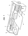
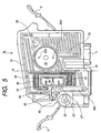
- Fig. 1 is a view showing an example of an ink-jet recording apparatus employing an ink cartridge according to the invention.
- Ink cartridges to which the present invention is applied (hereinafter referred to simply as “cartridges") are mounted on a carriage 75 of the ink-jet recording apparatus.
- the carriage 75 has a recording head 73 attached thereto.
- the carriage 75 is connected to a stepping motor 79 by way of a timing belt 77 and is guided by a guide bar 78, to travel back and forth across the width of recording paper (i.e., a primary scanning direction) .
- the carriage 75 has substantially a box-like shape having an open top.
- the recording head 73 is mounted on the carriage 75 such that a nozzle surface of the recording head 73 is exposed at the surface of the carriage 75 opposing recording paper 76 (i.e., a lower surface of the carriage 75 in this example) .
- the cartridges 1 are mounted on the carriage 75.
- Ink is supplied from the ink cartridges 1 to the recording head 73. Ink droplets are ejected onto an upper surface of the recording paper 76 while the carriage 75 is being moved, thereby printing an image or characters on the recording paper 76 in the form of a matrix of dots.
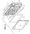
- Figs. 2 and 3 are exploded perspective views showing an embodiment of the cartridge 1 of the invention.
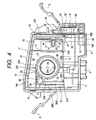
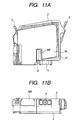
- Fig. 4 is a view of a container main body 2 when viewed from an opening side thereof.
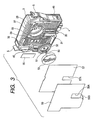
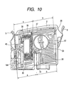
- Fig. 5 is a view of the container main body 2 when viewed from a front surface side thereof (the surface of the container main body 2 opposite the opening side thereof will be hereinafter called a "front surface of the container main body 2").
- the cartridge 1 has a flat, rectangular, box-shaped container main body 2 which is open at one surface (i.e., a left side surface as viewed in Fig. 2); and a cover member 3 welded to the open surface to seal the opening. Both the container main body 2 and the closure 3 are made of synthetic resin.
- ink flow grooves 35, 18A which are to act as ink flow paths; and an atmosphere communication groove 36 which is to act as an atmosphere communication path.
- a single first film 57 possessing a gas impermeability is welded to the front surface of the container main body 2 so that openings of the ink flow grooves 35, 18A and atmosphere communication groove 36 are sealed, whereby the ink flow grooves 35, 18A constitute ink flow paths, and the atmosphere communication groove 36 constitutes an atmosphere communication path.
- the cartridge 1 of the invention is formed with the flow paths by sealing the opening of the ink flow groove 35 and that of the atmosphere communication groove 36 formed in the surface of the container main body 2 using the first film 57.
- a container having comparatively-complicated flow paths, such as an ink flow path and an atmosphere communication path, can be readily formed, thereby facilitating designing or processing of a molding die and enabling low-cost manufacture of an ink cartridge.
- An ink supply port 4 is formed in the leading end surface of the container main body 2 in a direction in which the container main body 2 is to be inserted into the carriage 75 (i.e., in a bottom surface in the embodiment).
- Grip arms 5 and 6 to be gripped at the time of removal or attachment of the cartridge 1 are formed integrally with forward and backward surfaces (i.e., a right-side surface and a left-side surface in Fig. 4) of the container main body 2.
- a valve member (not shown) to be opened by insertion of an ink supply needle is housed in the ink supply port 4.
- reference numeral 49 designates a memory device provided in a portion of the container main body 2 close to the ink supply port 4 and below the grip arm 6.
- a frame section 14 including a wall 10 which extends in a substantially horizontal direction and is sloped slightly downward toward the ink supply port 4.
- the frame section 14 is spaced at a substantially uniform clearance from a ceiling surface and both side surfaces of the container main body 2.
- An area located beneath the frame section 14 forms a first ink chamber 11 for storing ink.
- the clearance formed between the frame section 14, and the outer peripheral wall of the container main body 2 and a wall 12 provided along the side of the frame section 14 opposing a valve storage chamber 8 constitute atmosphere communication paths 13, 13A which bring the first ink chamber 11 in communication with the atmosphere by way of a through hole 67.
- the cover 3 is attached to the wall 12 and the outer peripheral wall of the container main body 2 by means of fusing, thus constituting the atmosphere communication path 13A.
- the upper end of the wall 12 constituting the atmosphere communication path 13A extends up to the neighborhood of the ceiling of the container main body 2 so as to protrude upward from a fluid level of the ink stored in the first ink chamber 11 when the ink cartridge is in use.
- an opening of the atmosphere communication path 13A is opened at a location upward from the fluid level of the ink stored in the first ink chamber 11, thereby preventing, to the extent possible, reverse flow of ink into the through hole 67.
- the inside of the frame section 14 is divided into left and right sub-divisions by a wall 15.
- a communication port 15A through which ink flows is formed in a bottom of the wall 15, and the wall 15 extends in a vertical direction.
- the sub-division that is divided by the wall 15 and is located on the right side of the drawing forms a second ink chamber 16 for temporarily storing the ink sucked up from the first ink chamber 11.
- Formed in the sub-division located on the left side of the drawing are a third ink chamber 17, a fourth ink chamber 23, and a fifth ink chamber 34.
- a differential pressure regulating valve constituted of a membrane valve 52, a spring 50, etc. is also housed in the left-side sub-division.
- a suction flow path 18 Formed in the area of the first ink chamber 11 located below the second ink chamber 16 is a suction flow path 18 which connects the second ink chamber 16 to surroundings of a bottom surface 2A of the container main body 2 to suck-up ink in the first ink chamber 11 into the second ink chamber 16.
- a rectangular region surrounded by a wall 19 is formed in an area located below the suction flow path 18.
- a communication port 19A is formed in a lower portion of the wall 19, and another communication port 19B is formed in an upper surface of the wall 19.
- the suction flow path 18 is defined by forming a channel-like ink flow groove 18A in the front surface of the container main body 2, and sealing the ink flow groove 18A with the first film 57.
- An upper portion of the suction flowpath 18 is in communication with the second ink chamber 16 by way of a communication port 47.
- An opening section 48 is formed in a lower portion of the suction flow path 18 located within the rectangular region surrounded by the wall 19.
- An opening 18B (see Fig. 9B) formed in the lower end of the suction flow path 18 is in communication with the first ink chamber 11.
- An ink injection port 20 to be used in injecting ink into the first ink chamber 11 is formed in an area on the bottom surface of the container main body 2 corresponding to the suction flow path 18.
- An air vent 21 which allows air to escape at the time of injection of ink is formed in the vicinity of the ink injection port 20.
- a wall 22 is formed in the third ink chamber 17 so as to extend horizontally while being spaced a given interval from an upper surface 14A of the frame section 14.
- the third ink chamber 17 is partitioned by a substantially-arc-shaped wall 24 continuous with the wall 22.
- a differential pressure regulating valve storage chamber 33 and the fifth ink chamber 34 are formed in the area surrounded by the wall 24.
- the area surrounded by the arc-shaped wall 24 is divided into two sub-divisions in the thickness direction, by a wall 25, such that a differential pressure regulating valve storage chamber 33 is formed in the area on the front surface side and opposite from the fifth ink chamber 34.
- the wall 25 has ink-flow-path ports 25A for guiding the ink having flowed into the fifth ink chamber 34 to the differential pressure regulating valve storage chamber 33.
- Apartition wall 26 having a communication port 26a is provided between a lower portion of the wall 24 and the wall 10.
- the area located downstream of the partition wall 26 (a left-side in Fig. 4) is formed as the fourth ink chamber 23.
- Interposed between the substantially arc-shaped wall 24 and the frame section 14 are a partition wall 27 and a partition wall 32.
- a communication port 27A is formed in a lower portion of the partition wall 27, and the partition wall 27 extends vertically.
- a communication ports 32A and 32B are respectively formed in upper and lower portions of the vertically extending partition wall 32.
- An arc-shaped wall 30 is formed in the container main body 2 so as to be continuous with an upper end section of the partition wall 27, and is connected to the substantially-arc-shaped wall 24 and the wall 22.
- An area surrounding by the substantially arc-shaped wall 30 is formed into a filter housing chamber 9 for housing a block-shaped filter (a cylindrical filter in the embodiment) therein.
- a through hole 29 having a combined shape of a large circle portion and a small circle portion is formed so as to extend across the circular-arc-shaped wall 30 constituting the filter housing chamber 9.
- the large circle portion of the through hole 29 is in communication with the upper portion of the ink flow path 28A, and the small circle portion of the through hole 29 is in communication with an upper portion of the fifth ink chamber 34 by way of a communication port 24A formed in a tip end portion of the substantially-arc-shaped wall 24.
- the ink flow path 28A and the fifth ink chamber 34 are in communication with each other by way of the through hole 29.
- the ink that has flowed into the through hole 29 flows from the small circle portion of the through hole 29 into the fifth ink chamber 34 by way of the communication port 24A.
- An opening of the through hole 29 formed in the front surface side of the container main body 2 is also sealed by the first film 57.
- a gas impermeable second film 56 is attached to the opening side of the frame section 14 by means of welding. That is, the second film 56 is attached to the frame section 14, the walls 10, 15, 22, 24, 30, and 42, and the partition walls 26, 27, and 32 by means of welding, thus constituting ink chambers and flow paths.
- a lower portion of the differential pressure regulation valve storage chamber 33 and the ink supply port 4 are in communication with each other via the flow path defined by the ink flow groove 35 formed in the front surface of the container main body 2 and the gas impermeable first film 57 covering the ink flow groove 35.
- the upper and lower ends of the ink flow groove 35 are respectively in communication with the differential pressure regulation valve storage chamber 33, and the ink supply port 4.
- the atmosphere communication groove 36 which meanders so as to increase flow resistance to the greatest possible extent; and a wide groove 37 which is in communication with the atmosphere communication groove 36 and surrounds the differential pressure regulating valve storage chamber 33 and the atmosphere communication groove 36. Further, a rectangular recess 38 is formed in an area in the front surface of the container main body 2 and corresponding to the second ink chamber 16.
- a frame section 39 and ribs 40 are formed within the rectangular recess 38 at a location lowered from an open edge of the recess 38.
- a gas permeable sheet 55 possessing an ink repellent characteristic is stretched over and attached onto the frame section 39 and the ribs 40.
- the inside of the rectangular recess 38 is formed into an atmosphere communication chamber which is in communication with the atmosphere by way of the atmosphere communication groove 36 and the groove 37.
- a through hole 41 is formed in a deep surface of the recess 38, and is in communication with a narrow, elongated area 43 defined by an elongated oval wall 42 provided within the second ink chamber 16.
- the area of the recess 38 closer to the front surface side than the gas permeable sheet 55 is located is in communication with the atmosphere communication groove 36.
- a through hole 44 is formed in the end of the narrow, elongated area 43 opposite from the through hole 41.
- the through hole 44 is in communication with the valve storage chamber 8 serving as an atmosphere release valve chamber, by way of a communicating groove 45 formed in the front surface side of the container main body 2 and a through hole 46 formed in communication with the groove 45.
- a through hole 60 is formed in the valve storage chamber 8 so as to be in communication with the through hole 67 formed in the atmosphere communication path 13A formed in the first ink chamber 11.
- the air that has entered the recess 38 by way of the atmosphere communication groove 36 reaches the valve storage chamber 8, by way of the through hole 41, the narrow, elongated area 43, and the through holes 44, 46.
- the air further reaches the first ink chamber 11 from the valve,storage chamber 8, by way of the through hole 60, the communication hole 67, and the atmosphere communication paths 13, 13A.
- the cartridge insertion side of the valve storage chamber 8 (i.e., a bottom surface in the embodiment) is opened. As will be described later, identification pieces and an operation lever provided on a recording apparatus main unit can enter into the storage chamber 8 through the opening. Housed in an upper portion of the valve storage chamber 8 is an atmosphere release valve which opens upon entry of the operation lever, thereby maintaining a normally-open valve status.
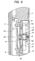
- Fig. 6 shows a cross-sectional view of the structure located in the vicinity of the fifth ink chamber 34 and the differential pressure regulating valve storage chamber 33.
- the right-side portion of the drawing shows the front surface side of the container main body 2 where the differential pressure regulating valve storage chamber 33 is located.
- Stored in the differential pressure regulating valve storage chamber 33 are the spring 50 and the membrane valve 52 formed of an elastically-deformable material, such as elastomer.
- the membrane valve 52 has a through hole 51 formed in the center thereof.
- the membrane valve 52 has an annular thick-walled section 52A in the periphery thereof, and is fastened to the container main body 2 by way of a frame section 54 formed integrally with the thick-walled section 52A.
- One end of the spring 50 is contacted with and supported by a spring receiving section 52B of the membrane valve 52, and the other end of the same is contacted with and supported by a spring receiving section 53A of a lid member 53 which closes the differential pressure regulating valve storage chamber 33.
- the membrane 52 blocks flow of the ink that has flowed from the fifth ink chamber 34 and passed through the ink-flow-path ports 25A. If the pressure of the ink supply port 4 has dropped in this state, the membrane valve 52 is separated from a valve seat section 25B against the urging force of the spring 50, by the negative pressure. Hence, the ink passes through the through hole 51 and flows into the ink supply port 4 via the flow path defined by the ink flow groove 35.
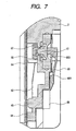
- Fig. 7 shows a cross-sectional view of the structure of the valve storage chamber 8 for use in communication with the atmosphere.
- the right-side portion of the drawing shows the front surface side of the container main body 2.
- a through hole 60 is formed in the partition wall defining the valve storage chamber 8.
- a press member 61 constituted of an elastic member, such as rubber, is fitted into the through hole 60 in a movable manner while surroundings of the press member 61 are supported by the container main body 2.
- a valve member 65 is disposed on the leading end of the press member 61 in the entry side so that the valve member 65 is supported by an elastic member 62, and constantly urged onto the through hole 60.
- a plate spring is used as the elastic member 62, such that the lower end of the spring is fixed by a projection 63 and the central portion of the spring is regulated by projections 64.
- An arm 66 is disposed on the other side of the press member 61.
- the cartridge insertion direction side of the arm 66 i.e., a lower end in the embodiment
- the pulling-out side of the arm 66 i.e., an upper side in the embodiment
- a protuberance 66B is formed at the leading end of the arm 66 for resiliently pressing the press member 61.
- the through hole 67 formed in an upper portion of the first ink chamber 11 is connected to the atmosphere communicating recess 38 by way of the through hole 60, the valve storage 8, the through hole 46, the groove 45, the through hole 44, the narrow, elongated region 43 and the through hole 41.
- a identification projection 68 is provided in the valve storage chamber 8 at a location closer to the insertion direction side (i.e., the lower side in the embodiment) than the arm 66 is located, for identifying whether or not the cartridges 1 are suitable for the recording apparatus.
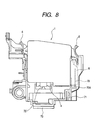
- the identification projection 68 is disposed at such a location that a determination can be made through use of the identification piece (operating rod) 70 before the ink supply port 4 is connected to the ink supply needle 72 (see Fig. 8) and the valve member 65 is opened.
- the gas impermeable first film 57 is attached to the front surface of the container main body 2 so as to cover at least the area having the recess formed therein, after all the components, such as valves, are incorporated into the container main body 2.
- a capillary serving as an atmosphere communication path is formed in the front surface side of the container main body 2 by the recess and the first film 57.
- the single first film 57 is welded to the front surface of the container main body 2 of the cartridge 1 to seal the openings of the ink flow groove 35, the through hole 29, the ink flow groove 18A, the groove 45, the atmosphere communication groove 36, and the recess 38 in the front surface of the container main body 2, whereby the ink flow groove 35, the through hole 29, the ink flow groove 18A, and the groove 45 define respective ink flow paths, and the atmosphere communication groove 36 and the recess 38 define respective atmosphere communication paths.
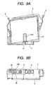
- Fig. 9 shows a state of the cartridge 1 where the first film 57 has been welded thereto.
- the first time 57 is welded to the front surface of the container main body 2, by such a thermal welding method that the first film 57 is applied to cover the front surface of the container main body 2, and pressed using a heating/pressurizing plate.
- the atmosphere communication groove 36 is formed as a shallow, narrow, complicatedly-bent groove in order to prevent evaporation of ink to the extent possible and to avoid an unduly increased flow resistance. Therefore, when the atmosphere communication groove 36 is sealed by the first film 57, the atmosphere communication groove 36 may be collapsed or destroyed to hinder an air communication unless the height at which the first film 57 is to be welded is controlled with high precision. On the other hand, it is preferably that the welding, the importance of which is given to welding strength is carried out for the recess constituting an ink flow path, such as the ink groove 35, in order to prevent leakage of ink.
- the layout of flow paths in the front surface of the container main body 2 is such that the front surface can be roughly divided into a region (b) where recesses, such as the ink flow groove 35 and the through hole 29, defining the ink flow paths are primarily disposed, and a region (a) where the atmosphere communication groove 36 is primarily disposed. Further, a groove 31 that does not form a flow path is disposed in a boundary between regions (a) and (b) in the front surface of the container main body 2.
- a range where the first film 57 is pressurized at one time using one heating/pressurizing plate when the first film 57 is welded to the container main body 2 (hereinafter called a "welding region") is set as each of divided regions (a) and (b) where the region (a) primarily requires management of precision for welding height, and the region (b) primarily requires management of welding strength. Welding requirements or conditions are controlled independently in the respective regions (a) and (b) . As a result, welding precision and welding strength can be managed concurrently. Further, since the control of a welding status for a relatively small area is made possible, setup of welding requirements can be performed comparatively readily.
- the region of the first film 57 to be welded is divided into the region (b), where the ink flow groove 35 is formed, which defines the ink flow path located downstream of the differential pressure valve generating negative pressure within the cartridge 1, and the other region (a). That is, in case of the cartridge 1 having the differential pressure regulating valve, the geometries of flow paths, such as the ink flow paths and atmosphere communication paths, become comparatively complicated, and therefore a noticeable effect can be obtained to readily form the complicated flow paths.
- reference numeral 57A designates a notch provided in the area of the first film 57 corresponding to the groove 31.
- an over-sheet 59 for covering the first film 57 is attached to the front surface side of the container main body 2.
- the over-sheet 59 protects the first film 57, thereby preventing leakage of ink caused by damage of the first film 57, and eliminating evaporation of ink.
- reference numeral 59A designates a notch formed in the area of the over-sheet 59 corresponding to the groove 31.
- a sheet which is thicker than the first film 57 is used as the over-sheet 59. That is, in the case of the cartridge 1 mentioned above, the thickness of the first film 57 is set smaller than that of the over-sheet 59. As a result, when the ink grooves 35, 18A, the atmosphere communication groove 36, etc. are sealed by welding the first film 57, the first film 57 is readily overlaid along the front surface of the container main body 2, and hence it is advantageous in improving welding strength and precision. The first film 57 can be effectively protected by the relatively thick over-sheet 59.
- the over-sheet 59 is formed with an extended area 59B for covering a portion of the lower surface of the container main body 2, and the extended area 59B covers the ink injection port 20 and the air outlet port 21.
- the single over-sheet 59 can cover up to the ink injection port 20 and the air outlet port 21, and hence it is advantageous in simplifying manufacturing processes and reducing the number of components.
- the gas impermeable second film 56 is thermally-welded to the opening section of the container main body 2 to be hermetic with respect to the frame section 14, the walls 10, 15, 22, 24, 30, and 42, and the partition walls 26, 27, and 32.
- the cover 3 is further placed over the second film 56 and fixed by welding. As a result, the areas partitioned by the walls are sealed so as to be in communication by way of only communication ports or openings.
- the container main body 2 can be formed readily, and also ink pressure can be maintained as constant as possible because fluctuations in ink stemming from reciprocal movement of the carriage can be absorbed by deformation of the first and second films 56, 57.
- an ink injection tube is inserted into the ink injection port 20, and sufficiently degassed ink is injected while the air outlet port 21 is remained open. After completion of injection of ink, the ink injection port 20 and the air outlet port 21 are sealed with a film and the over-sheet 59.
- the ink cartridge 1 having such a construction is preserved while being isolated from the atmosphere by the valves, etc., the degassed rate of ink is sufficiently maintained.
- the ink supply port 4 enters up to a position where the ink supply needle 72 is inserted into the ink supply port 4.
- the through hole 60 is released by the operation rod 70, whereby the ink storage region is brought in communication with the atmosphere, and the valve of the ink supply port 4 is opened by the ink supply needle 72.
- the identification protuberance 68 comes into contact with an identification piece 70A of the holder 71 before the ink supply port 4 reaches the ink supply needle 72, thus hindering advancement of the ink supply port 4.
- the operation rod 70 is also unable to reach the arm 66.
- the valve member 65 maintains a sealed status, and release of the ink storage region to the atmosphere is hindered, thereby preventing evaporation of ink.
- the pressure of the ink supply port 4 drops to a specified level or less, and the membrane valve 52 is opened. Further, if the pressure of the ink supply port 4 has increased, the membrane valve 52 is closed. Thus, the ink maintained at predetermined negative pressure flows into the recording head 73.
- the ink stored in the first ink chamber 11 flows into the second ink chamber 16 by way of the suction flow path 18. Air bubbles having flowed into the second ink chamber 16 are elevated by means of buoyancy, and only ink flows into the third ink chamber 17 by way of the communication port 15A located in the low part of the second ink chamber 16.
- the ink stored in the third ink chamber 17 flows into the ink flow paths 28A, 28B by way of the fourth ink chamber 23 after having passed through the communication port 26A of the partition wall 26 formed in the lower end of the substantially-circular wall 24.
- the ink having flowed through the ink flow path 28A flows into the filter storage chamber 9, where the ink is filtrated by the filter 7.
- the ink having passed through the filter storage chamber 9 flows through the large and small circle portions of the through hole 29 and enters an upper portion of the fifth ink chamber 34 after having passed through the communication port 24A.
- the ink having flowed into the fifth ink chamber 34 flows into the differential pressure regulating valve storage chamber 33 after having passed through the ink-flow-path port 25A.
- the ink flows into the ink supply port 4 at predetermined negative pressure by opening and closing actions of the membrane valve 52.
- the first ink chamber 11 is in communication with the atmosphere by way of the atmosphere communication paths 13, 13A, the through hole 67, the valve storage chamber 8, etc., and is maintained at the atmospheric pressure. Hence, there does not arise a hindrance to an ink flow, which would otherwise be caused by generation of negative pressure. Even if the ink stored in the first ink chamber 11 has reversely flowed into the recess 38, the ink-repellent gas permeable sheet 55 provided on the recess 38 maintains communication with the atmosphere, while preventing the flow-out of ink. Thus, it is possible to prevent clogging in the atmosphere communication groove 36, which would otherwise be caused when ink has flowed into the atmosphere communication groove 36 and solidified there.
- the ink flow groove 35 and the like, and the atmosphere communication groove 36 are formed in the front surface of the container main body 2, and the openings of these grooves are sealed by the first film 75, thus constituting flow paths.
- a container having comparatively complicated flow paths, such as ink flow paths and atmosphere communication paths Therefore, designing and machining of a molding die are facilitated, thereby enabling lower-cost manufacture of an ink cartridge.
- the embodiment has illustrated, while taking an example in which a columnar filter is used as the filter 7.
- the invention is not limited to that example. Filters of various sizes and shapes may be used, so long as the filters assume the shape of a block.
- an ink cartridge of the invention a recess for ink and an atmosphere communication groove are formed in the front surface of a container, and an openings of the recess and the groove are sealed by a film, thereby constituting flow paths.
- a container having comparatively complicated flow paths such as an ink flow path and an atmosphere communication path. Therefore, designing and machining of a molding die are facilitated, thereby enabling lower-cost manufacture of an ink cartridge.
- reference character A designates an example of an imaginary straight line that is substantially parallel to an insertion direction B of an ink cartridge to a recording apparatus and that defines first and second sides of the ink cartridge.
Landscapes
- Ink Jet (AREA)
- Pens And Brushes (AREA)
Priority Applications (1)
| Application Number | Priority Date | Filing Date | Title |
|---|---|---|---|
| EP06005323A EP1669200B1 (de) | 2001-05-17 | 2002-05-17 | Tintenkartusche |
Applications Claiming Priority (4)
| Application Number | Priority Date | Filing Date | Title |
|---|---|---|---|
| JP2001148296 | 2001-05-17 | ||
| JP2001148296 | 2001-05-17 | ||
| JP2001149786 | 2001-05-18 | ||
| JP2001149786 | 2001-05-18 |
Related Child Applications (1)
| Application Number | Title | Priority Date | Filing Date |
|---|---|---|---|
| EP06005323A Division EP1669200B1 (de) | 2001-05-17 | 2002-05-17 | Tintenkartusche |
Publications (2)
| Publication Number | Publication Date |
|---|---|
| EP1258360A1 true EP1258360A1 (de) | 2002-11-20 |
| EP1258360B1 EP1258360B1 (de) | 2008-03-26 |
Family
ID=26615282
Family Applications (2)
| Application Number | Title | Priority Date | Filing Date |
|---|---|---|---|
| EP02010258A Expired - Lifetime EP1258360B1 (de) | 2001-05-17 | 2002-05-17 | Tintenkartusche |
| EP06005323A Expired - Lifetime EP1669200B1 (de) | 2001-05-17 | 2002-05-17 | Tintenkartusche |
Family Applications After (1)
| Application Number | Title | Priority Date | Filing Date |
|---|---|---|---|
| EP06005323A Expired - Lifetime EP1669200B1 (de) | 2001-05-17 | 2002-05-17 | Tintenkartusche |
Country Status (13)
| Country | Link |
|---|---|
| US (2) | US6945641B2 (de) |
| EP (2) | EP1258360B1 (de) |
| JP (1) | JP2003034042A (de) |
| KR (1) | KR100477155B1 (de) |
| CN (3) | CN2602931Y (de) |
| AT (2) | ATE414614T1 (de) |
| CA (1) | CA2386724C (de) |
| DE (2) | DE60229986D1 (de) |
| ES (2) | ES2318597T3 (de) |
| HK (1) | HK1049308A1 (de) |
| MY (2) | MY128925A (de) |
| SG (1) | SG119151A1 (de) |
| TW (1) | TWI251545B (de) |
Cited By (2)
| Publication number | Priority date | Publication date | Assignee | Title |
|---|---|---|---|---|
| WO2008134317A1 (en) | 2007-04-24 | 2008-11-06 | Hewlett-Packard Development Company, L.P. | Compact ink delivery in an ink pen |
| CN1990254B (zh) * | 2005-12-28 | 2011-01-26 | 佳能株式会社 | 液体储存容器 |
Families Citing this family (45)
| Publication number | Priority date | Publication date | Assignee | Title |
|---|---|---|---|---|
| JP3582592B2 (ja) * | 2001-04-03 | 2004-10-27 | セイコーエプソン株式会社 | インクカートリッジ、及びインクジェット記録装置 |
| JPH08174860A (ja) * | 1994-10-26 | 1996-07-09 | Seiko Epson Corp | インクジェットプリンタ用インクカートリッジ |
| DE69733176T2 (de) | 1996-02-21 | 2006-02-16 | Seiko Epson Corp. | Tintenkartusche |
| JP4141523B2 (ja) | 1997-03-19 | 2008-08-27 | セイコーエプソン株式会社 | インク供給流路の弁装置 |
| ATE386640T1 (de) | 1998-07-15 | 2008-03-15 | Seiko Epson Corp | Tintenzufuhrvorrichtung |
| CN1280103C (zh) * | 2000-02-16 | 2006-10-18 | 精工爱普生株式会社 | 喷墨打印机用连接组件及喷墨打印机 |
| US6935730B2 (en) * | 2000-04-03 | 2005-08-30 | Unicorn Image Products Co. Ltd. Of Zhuhai | One-way valve, valve unit assembly, and ink cartridge using the same |
| US20050243147A1 (en) * | 2000-10-12 | 2005-11-03 | Unicorn Image Products Co. Ltd. | Ink cartridge having bellows valve, ink filling method and apparatus used thereof |
| EP1967367B1 (de) * | 2000-10-20 | 2011-08-31 | Seiko Epson Corporation | Tintenpatrone für Tintenstrahlaufzeichnungsvorrichtung |
| ES2275603T5 (es) * | 2000-10-20 | 2010-07-07 | Seiko Epson Corporation | Dispositivo de registro de inyeccion de tinta y cartucho de tinta. |
| PT1481808E (pt) * | 2000-10-20 | 2007-02-28 | Seiko Epson Corp | Cartucho de tinta |
| CN2602931Y (zh) * | 2001-05-17 | 2004-02-11 | 精工爱普生株式会社 | 墨盒 |
| JP3991853B2 (ja) | 2002-09-12 | 2007-10-17 | セイコーエプソン株式会社 | インクカートリッジ |
| EP1602491B2 (de) * | 2002-11-26 | 2013-08-14 | Seiko Epson Corporation | Tintenpatrone |
| JP3624950B2 (ja) * | 2002-11-26 | 2005-03-02 | セイコーエプソン株式会社 | インクカートリッジ |
| JP2004268575A (ja) * | 2003-02-19 | 2004-09-30 | Seiko Epson Corp | 液体貯留手段及び液体噴射装置 |
| JP4241177B2 (ja) * | 2003-05-09 | 2009-03-18 | セイコーエプソン株式会社 | 液体噴射装置 |
| JP3848295B2 (ja) | 2003-05-16 | 2006-11-22 | キヤノン株式会社 | インクタンク |
| JP4261983B2 (ja) * | 2003-05-22 | 2009-05-13 | キヤノン株式会社 | インクタンク |
| JP4155879B2 (ja) * | 2003-06-25 | 2008-09-24 | 株式会社リコー | 液体容器、液体供給装置及び画像形成装置 |
| JP4492782B2 (ja) * | 2003-09-11 | 2010-06-30 | ブラザー工業株式会社 | インクカートリッジ及びインクジェット記録装置 |
| EP1757453A4 (de) | 2004-06-16 | 2010-02-24 | Seiko Epson Corp | Flüssigkeitslagerkörper |
| BRPI0506191A (pt) * | 2004-11-29 | 2006-07-25 | Seiko Epson Corp | processo de reenchimento de cartucho, dispositivo de reenchimento de lìquido e cartucho de reenchimento |
| US7255432B2 (en) * | 2005-03-30 | 2007-08-14 | Monitek Electronics Limited | Ink cartridge |
| US7775645B2 (en) | 2005-09-29 | 2010-08-17 | Brother Kogyo Kabushiki Kaisha | Methods of forming cartridges, such as ink cartridges |
| US7553007B2 (en) | 2005-09-29 | 2009-06-30 | Brother Kogyo Kabushiki Kaisha | Ink cartridges |
| US7837311B2 (en) | 2005-09-29 | 2010-11-23 | Brother Kogyo Kabushiki Kaisha | Ink cartridges |
| US8025376B2 (en) | 2005-09-29 | 2011-09-27 | Brother Kogyo Kabushiki Kaisha | Ink cartridges |
| US7810916B2 (en) | 2005-09-29 | 2010-10-12 | Brother Kogyo Kabushiki Kaisha | Ink cartridges |
| US7828421B2 (en) | 2005-09-29 | 2010-11-09 | Brother Kogyo Kabushiki Kaisha | Ink cartridge arrangements |
| US7682004B2 (en) | 2005-09-29 | 2010-03-23 | Brother Kogyo Kabushiki Kaisha | Ink cartridges |
| DE102007037912A1 (de) | 2006-08-11 | 2008-04-24 | Seiko Epson Corp. | Flüssigkeitseinspritzverfahren und Flüssigkeitsbehälter |
| JP5055888B2 (ja) * | 2006-08-11 | 2012-10-24 | セイコーエプソン株式会社 | 液体収容体の製造方法 |
| JP5055889B2 (ja) * | 2006-08-11 | 2012-10-24 | セイコーエプソン株式会社 | 液体収容体の製造方法 |
| DE102006050161A1 (de) * | 2006-10-25 | 2008-04-30 | Robert Bosch Gmbh | Reservoir für einen Kraftstoffbehälter |
| JP2008230214A (ja) * | 2007-02-19 | 2008-10-02 | Seiko Epson Corp | 流体導出部のシール構造体及びシール方法並びに流体収容容器、再充填流体収容容器及びその再充填方法 |
| JP4798033B2 (ja) * | 2007-03-20 | 2011-10-19 | ブラザー工業株式会社 | 液体充填方法 |
| JP5157327B2 (ja) * | 2007-08-31 | 2013-03-06 | ブラザー工業株式会社 | インク容器、及びインク容器の収容体 |
| CN101564936A (zh) * | 2008-04-23 | 2009-10-28 | 肯尼斯·袁 | 墨盒 |
| JP2009190410A (ja) * | 2009-06-01 | 2009-08-27 | Seiko Epson Corp | 液体噴射装置 |
| JP2013180522A (ja) * | 2012-03-02 | 2013-09-12 | Seiko Epson Corp | カートリッジ |
| JP6115029B2 (ja) * | 2012-05-31 | 2017-04-19 | セイコーエプソン株式会社 | 液体収容容器の製造方法 |
| US9487011B2 (en) * | 2014-06-11 | 2016-11-08 | Inkcycle, Inc. | Latch improvement for a printer supply |
| JP6355477B2 (ja) * | 2014-08-21 | 2018-07-11 | キヤノン株式会社 | インクジェット記録装置 |
| US10576744B2 (en) | 2017-11-16 | 2020-03-03 | Seiko Epson Corporation | Liquid discharge head and channel structure |
Citations (3)
| Publication number | Priority date | Publication date | Assignee | Title |
|---|---|---|---|---|
| EP1016533A1 (de) * | 1998-07-15 | 2000-07-05 | Seiko Epson Corporation | Tintenstrahlaufzeichnungsgerät mit farbzufuhreinheit |
| JP2001148296A (ja) | 1999-11-19 | 2001-05-29 | Sanken Electric Co Ltd | チョッパとインバータとの組合せ電源装置 |
| JP2001149786A (ja) | 1999-11-26 | 2001-06-05 | Petroleum Energy Center | ベンゼンのトランスアルキレーション用メタロシリケート触媒とそれを用いたベンゼンのトランスアルキル化方法 |
Family Cites Families (39)
| Publication number | Priority date | Publication date | Assignee | Title |
|---|---|---|---|---|
| JPS5656874A (en) | 1979-10-17 | 1981-05-19 | Canon Inc | Ink jet recording device |
| US4460905A (en) * | 1982-03-29 | 1984-07-17 | Ncr Corporation | Control valve for ink jet nozzles |
| US4555719A (en) | 1983-08-19 | 1985-11-26 | Videojet Systems International, Inc. | Ink valve for marking systems |
| US4677447A (en) | 1986-03-20 | 1987-06-30 | Hewlett-Packard Company | Ink jet printhead having a preloaded check valve |
| US5025271A (en) | 1986-07-01 | 1991-06-18 | Hewlett-Packard Company | Thin film resistor type thermal ink pen using a form storage ink supply |
| JP3169958B2 (ja) | 1990-10-05 | 2001-05-28 | セイコーエプソン株式会社 | インクタンク |
| JP2840482B2 (ja) | 1991-06-19 | 1998-12-24 | キヤノン株式会社 | インクタンク及びインクジェットヘッドカートリッジ、並びにインクジェット記録装置 |
| US5280300A (en) | 1991-08-27 | 1994-01-18 | Hewlett-Packard Company | Method and apparatus for replenishing an ink cartridge |
| JP2716883B2 (ja) | 1991-07-08 | 1998-02-18 | 株式会社テック | インク供給装置 |
| US5363130A (en) | 1991-08-29 | 1994-11-08 | Hewlett-Packard Company | Method of valving and orientation sensitive valve including a liquid for controlling flow of gas into a container |
| CA2272155C (en) | 1992-07-31 | 2004-05-25 | Canon Kabushiki Kaisha | Liquid storing container for recording apparatus |
| TW373595U (en) | 1994-05-25 | 1999-11-01 | Canon Kk | An ink container and an ink jet recording apparatus using the same |
| JPH08174860A (ja) * | 1994-10-26 | 1996-07-09 | Seiko Epson Corp | インクジェットプリンタ用インクカートリッジ |
| US5777647A (en) | 1994-10-31 | 1998-07-07 | Hewlett-Packard Company | Side-loaded pressure regulated free-ink ink-jet pen |
| US5721576A (en) | 1995-12-04 | 1998-02-24 | Hewlett-Packard Company | Refill kit and method for refilling an ink supply for an ink-jet printer |
| JP3225808B2 (ja) | 1995-10-16 | 2001-11-05 | セイコーエプソン株式会社 | インクジェットプリンタ |
| US5732751A (en) * | 1995-12-04 | 1998-03-31 | Hewlett-Packard Company | Filling ink supply containers |
| US5900895A (en) * | 1995-12-04 | 1999-05-04 | Hewlett-Packard Company | Method for refilling an ink supply for an ink-jet printer |
| DE19545775C2 (de) * | 1995-12-07 | 1999-03-25 | Pelikan Produktions Ag | Flüssigkeitspatrone, insbesondere Tintenpatrone für einen Druckkopf eines Ink-Jet-Printers |
| JP3503324B2 (ja) | 1996-02-01 | 2004-03-02 | ブラザー工業株式会社 | インクジェットプリンタのインクカートリッジ |
| DE69733176T2 (de) | 1996-02-21 | 2006-02-16 | Seiko Epson Corp. | Tintenkartusche |
| JPH09272210A (ja) | 1996-04-05 | 1997-10-21 | Canon Inc | インクジェット用液体保存容器 |
| JP3450643B2 (ja) | 1996-04-25 | 2003-09-29 | キヤノン株式会社 | 液体収容容器への液体補充方法、該補充方法を用いる液体吐出記録装置、液体補充容器、液体収容容器およびヘッドカートリッジ |
| US5847735A (en) | 1996-04-26 | 1998-12-08 | Pelikan Produktions Ag | Ink cartridge for a printer |
| JP3351455B2 (ja) | 1996-08-13 | 2002-11-25 | セイコーエプソン株式会社 | インクカートリッジ |
| JP3391221B2 (ja) | 1997-06-16 | 2003-03-31 | セイコーエプソン株式会社 | インクカートリッヂ |
| EP1281526B1 (de) * | 1998-02-13 | 2005-09-14 | Seiko Epson Corporation | Verfahren zur Wiederherstellung der Tintenstrahltropfenausstossfähigkeit |
| JP3173601B2 (ja) | 1998-05-13 | 2001-06-04 | セイコーエプソン株式会社 | インクジェット記録装置用のインクカートリッジ |
| DE69936947D1 (de) | 1998-05-13 | 2007-10-04 | Seiko Epson Corp | Tintenpatrone für Tintenstrahlaufzeichnungsgerät |
| JP4117432B2 (ja) | 1998-06-09 | 2008-07-16 | セイコーエプソン株式会社 | インクカートリッジ |
| US6299296B2 (en) | 1998-07-31 | 2001-10-09 | Hewlett Packard Company | Sealing member for a fluid container |
| KR100411028B1 (ko) * | 1999-03-29 | 2003-12-18 | 세이코 엡슨 가부시키가이샤 | 잉크 카트리지의 잉크 충전 방법 및 그 장치 |
| JP3258310B2 (ja) | 2000-01-01 | 2002-02-18 | キヤノン株式会社 | インクタンクおよびインクジェット装置 |
| CN1280103C (zh) | 2000-02-16 | 2006-10-18 | 精工爱普生株式会社 | 喷墨打印机用连接组件及喷墨打印机 |
| JP2001341324A (ja) | 2000-03-30 | 2001-12-11 | Seiko Epson Corp | インクジェット記録装置用インクカートリッジ、及びインクジェット記録装置 |
| EP1967367B1 (de) * | 2000-10-20 | 2011-08-31 | Seiko Epson Corporation | Tintenpatrone für Tintenstrahlaufzeichnungsvorrichtung |
| ES2275603T5 (es) * | 2000-10-20 | 2010-07-07 | Seiko Epson Corporation | Dispositivo de registro de inyeccion de tinta y cartucho de tinta. |
| CA2379725C (en) * | 2001-04-03 | 2007-06-12 | Seiko Epson Corporation | Ink cartridge |
| CN2602931Y (zh) * | 2001-05-17 | 2004-02-11 | 精工爱普生株式会社 | 墨盒 |
-
2002
- 2002-05-17 CN CNU022430253U patent/CN2602931Y/zh not_active Expired - Fee Related
- 2002-05-17 ES ES06005323T patent/ES2318597T3/es not_active Expired - Lifetime
- 2002-05-17 US US10/150,479 patent/US6945641B2/en not_active Expired - Lifetime
- 2002-05-17 EP EP02010258A patent/EP1258360B1/de not_active Expired - Lifetime
- 2002-05-17 AT AT06005323T patent/ATE414614T1/de not_active IP Right Cessation
- 2002-05-17 DE DE60229986T patent/DE60229986D1/de not_active Expired - Lifetime
- 2002-05-17 ES ES02010258T patent/ES2301584T3/es not_active Expired - Lifetime
- 2002-05-17 KR KR10-2002-0027418A patent/KR100477155B1/ko not_active IP Right Cessation
- 2002-05-17 EP EP06005323A patent/EP1669200B1/de not_active Expired - Lifetime
- 2002-05-17 MY MYPI20021837A patent/MY128925A/en unknown
- 2002-05-17 MY MYPI20060309A patent/MY141471A/en unknown
- 2002-05-17 JP JP2002143629A patent/JP2003034042A/ja active Pending
- 2002-05-17 CN CNB021265062A patent/CN1176806C/zh not_active Expired - Fee Related
- 2002-05-17 AT AT02010258T patent/ATE390288T1/de not_active IP Right Cessation
- 2002-05-17 TW TW091110375A patent/TWI251545B/zh not_active IP Right Cessation
- 2002-05-17 DE DE60225752T patent/DE60225752T2/de not_active Expired - Lifetime
- 2002-05-17 CA CA002386724A patent/CA2386724C/en not_active Expired - Fee Related
- 2002-05-17 SG SG200203001A patent/SG119151A1/en unknown
- 2002-05-17 CN CNB2004100632559A patent/CN1298542C/zh not_active Expired - Lifetime
-
2003
- 2003-02-28 HK HK03101530.2A patent/HK1049308A1/zh unknown
-
2004
- 2004-09-01 US US10/931,765 patent/US7213913B2/en not_active Expired - Lifetime
Patent Citations (3)
| Publication number | Priority date | Publication date | Assignee | Title |
|---|---|---|---|---|
| EP1016533A1 (de) * | 1998-07-15 | 2000-07-05 | Seiko Epson Corporation | Tintenstrahlaufzeichnungsgerät mit farbzufuhreinheit |
| JP2001148296A (ja) | 1999-11-19 | 2001-05-29 | Sanken Electric Co Ltd | チョッパとインバータとの組合せ電源装置 |
| JP2001149786A (ja) | 1999-11-26 | 2001-06-05 | Petroleum Energy Center | ベンゼンのトランスアルキレーション用メタロシリケート触媒とそれを用いたベンゼンのトランスアルキル化方法 |
Cited By (5)
| Publication number | Priority date | Publication date | Assignee | Title |
|---|---|---|---|---|
| CN1990254B (zh) * | 2005-12-28 | 2011-01-26 | 佳能株式会社 | 液体储存容器 |
| WO2008134317A1 (en) | 2007-04-24 | 2008-11-06 | Hewlett-Packard Development Company, L.P. | Compact ink delivery in an ink pen |
| EP2139693A1 (de) * | 2007-04-24 | 2010-01-06 | Hewlett-Packard Development Company, L.P. | Kompakte tintenausgabe in einem tintenstift |
| EP2139693A4 (de) * | 2007-04-24 | 2010-06-02 | Hewlett Packard Development Co | Kompakte tintenausgabe in einem tintenstift |
| US7922312B2 (en) | 2007-04-24 | 2011-04-12 | Hewlett-Packard Development Company, L.P. | Compact ink delivery in an ink pen |
Also Published As
| Publication number | Publication date |
|---|---|
| US7213913B2 (en) | 2007-05-08 |
| HK1049308A1 (zh) | 2003-05-09 |
| DE60225752D1 (de) | 2008-05-08 |
| ES2301584T3 (es) | 2008-07-01 |
| CN2602931Y (zh) | 2004-02-11 |
| EP1669200A1 (de) | 2006-06-14 |
| ATE390288T1 (de) | 2008-04-15 |
| DE60225752T2 (de) | 2009-04-09 |
| MY128925A (en) | 2007-02-28 |
| EP1258360B1 (de) | 2008-03-26 |
| EP1669200B1 (de) | 2008-11-19 |
| CN1390705A (zh) | 2003-01-15 |
| DE60229986D1 (de) | 2009-01-02 |
| ES2318597T3 (es) | 2009-05-01 |
| SG119151A1 (en) | 2006-02-28 |
| US20020180849A1 (en) | 2002-12-05 |
| US6945641B2 (en) | 2005-09-20 |
| KR100477155B1 (ko) | 2005-03-18 |
| TWI251545B (en) | 2006-03-21 |
| CA2386724C (en) | 2007-07-03 |
| CN1176806C (zh) | 2004-11-24 |
| US20050030357A1 (en) | 2005-02-10 |
| CA2386724A1 (en) | 2002-11-17 |
| CN1298542C (zh) | 2007-02-07 |
| MY141471A (en) | 2010-04-30 |
| ATE414614T1 (de) | 2008-12-15 |
| KR20020088398A (ko) | 2002-11-27 |
| JP2003034042A (ja) | 2003-02-04 |
| CN1550342A (zh) | 2004-12-01 |
Similar Documents
| Publication | Publication Date | Title |
|---|---|---|
| EP1258360B1 (de) | Tintenkartusche | |
| KR100481536B1 (ko) | 잉크 카트리지 및 그 잉크 주입 방법 | |
| KR100588287B1 (ko) | 잉크 카트리지 및 유체 유동 제어방법 | |
| US7784930B2 (en) | Ink cartridge for ink jet recording device | |
| KR100481535B1 (ko) | 잉크 카트리지 및 그 잉크 주입 방법 | |
| JP2003080730A (ja) | インクカートリッジおよびこれを用いたインクジェット式記録装置 | |
| JP4158833B2 (ja) | インクジェット記録装置用インクカートリッジ | |
| JP4438802B2 (ja) | インクカートリッジ | |
| JP4154619B2 (ja) | インクカートリッジ | |
| JP4296446B2 (ja) | インクカートリッジ | |
| JP4508223B2 (ja) | インクカートリッジ | |
| JP2003034041A (ja) | インクジェット記録装置用インクカートリッジ | |
| JP4296443B2 (ja) | インクカートリッジのインク注入方法 | |
| JP4114086B2 (ja) | インクカートリッジ | |
| JP4196221B2 (ja) | インクカートリッジ | |
| JP4296444B2 (ja) | インクカートリッジのインク注入方法 | |
| JP2003025600A (ja) | インクカートリッジ | |
| JP4296445B2 (ja) | インクカートリッジ | |
| JP2003072093A (ja) | インクカートリッジおよびそのインク注入方法 | |
| JP2003145784A (ja) | インクカートリッジ及びインクカートリッジにおける大気開放弁の組付方法 |
Legal Events
| Date | Code | Title | Description |
|---|---|---|---|
| PUAI | Public reference made under article 153(3) epc to a published international application that has entered the european phase |
Free format text: ORIGINAL CODE: 0009012 |
|
| AK | Designated contracting states |
Kind code of ref document: A1 Designated state(s): AT BE CH CY DE DK ES FI FR GB GR IE IT LI LU MC NL PT SE TR |
|
| AX | Request for extension of the european patent |
Free format text: AL;LT;LV;MK;RO;SI |
|
| 17P | Request for examination filed |
Effective date: 20021113 |
|
| AKX | Designation fees paid |
Designated state(s): AT BE CH CY DE DK ES FI FR GB GR IE IT LI LU MC NL PT SE TR |
|
| 17Q | First examination report despatched |
Effective date: 20051031 |
|
| GRAP | Despatch of communication of intention to grant a patent |
Free format text: ORIGINAL CODE: EPIDOSNIGR1 |
|
| GRAS | Grant fee paid |
Free format text: ORIGINAL CODE: EPIDOSNIGR3 |
|
| GRAA | (expected) grant |
Free format text: ORIGINAL CODE: 0009210 |
|
| AK | Designated contracting states |
Kind code of ref document: B1 Designated state(s): AT BE CH CY DE DK ES FI FR GB GR IE IT LI LU MC NL PT SE TR |
|
| REG | Reference to a national code |
Ref country code: GB Ref legal event code: FG4D |
|
| REG | Reference to a national code |
Ref country code: IE Ref legal event code: FG4D Ref country code: CH Ref legal event code: EP |
|
| REF | Corresponds to: |
Ref document number: 60225752 Country of ref document: DE Date of ref document: 20080508 Kind code of ref document: P |
|
| REG | Reference to a national code |
Ref country code: ES Ref legal event code: FG2A Ref document number: 2301584 Country of ref document: ES Kind code of ref document: T3 |
|
| PG25 | Lapsed in a contracting state [announced via postgrant information from national office to epo] |
Ref country code: FI Free format text: LAPSE BECAUSE OF FAILURE TO SUBMIT A TRANSLATION OF THE DESCRIPTION OR TO PAY THE FEE WITHIN THE PRESCRIBED TIME-LIMIT Effective date: 20080326 |
|
| PG25 | Lapsed in a contracting state [announced via postgrant information from national office to epo] |
Ref country code: AT Free format text: LAPSE BECAUSE OF FAILURE TO SUBMIT A TRANSLATION OF THE DESCRIPTION OR TO PAY THE FEE WITHIN THE PRESCRIBED TIME-LIMIT Effective date: 20080326 |
|
| NLV1 | Nl: lapsed or annulled due to failure to fulfill the requirements of art. 29p and 29m of the patents act | ||
| PG25 | Lapsed in a contracting state [announced via postgrant information from national office to epo] |
Ref country code: BE Free format text: LAPSE BECAUSE OF FAILURE TO SUBMIT A TRANSLATION OF THE DESCRIPTION OR TO PAY THE FEE WITHIN THE PRESCRIBED TIME-LIMIT Effective date: 20080326 |
|
| PG25 | Lapsed in a contracting state [announced via postgrant information from national office to epo] |
Ref country code: PT Free format text: LAPSE BECAUSE OF FAILURE TO SUBMIT A TRANSLATION OF THE DESCRIPTION OR TO PAY THE FEE WITHIN THE PRESCRIBED TIME-LIMIT Effective date: 20080901 Ref country code: SE Free format text: LAPSE BECAUSE OF FAILURE TO SUBMIT A TRANSLATION OF THE DESCRIPTION OR TO PAY THE FEE WITHIN THE PRESCRIBED TIME-LIMIT Effective date: 20080626 |
|
| PG25 | Lapsed in a contracting state [announced via postgrant information from national office to epo] |
Ref country code: NL Free format text: LAPSE BECAUSE OF FAILURE TO SUBMIT A TRANSLATION OF THE DESCRIPTION OR TO PAY THE FEE WITHIN THE PRESCRIBED TIME-LIMIT Effective date: 20080326 |
|
| PG25 | Lapsed in a contracting state [announced via postgrant information from national office to epo] |
Ref country code: MC Free format text: LAPSE BECAUSE OF NON-PAYMENT OF DUE FEES Effective date: 20080531 |
|
| REG | Reference to a national code |
Ref country code: CH Ref legal event code: PL |
|
| ET | Fr: translation filed | ||
| PG25 | Lapsed in a contracting state [announced via postgrant information from national office to epo] |
Ref country code: LI Free format text: LAPSE BECAUSE OF NON-PAYMENT OF DUE FEES Effective date: 20080531 Ref country code: CH Free format text: LAPSE BECAUSE OF NON-PAYMENT OF DUE FEES Effective date: 20080531 Ref country code: DK Free format text: LAPSE BECAUSE OF FAILURE TO SUBMIT A TRANSLATION OF THE DESCRIPTION OR TO PAY THE FEE WITHIN THE PRESCRIBED TIME-LIMIT Effective date: 20080326 |
|
| PLBE | No opposition filed within time limit |
Free format text: ORIGINAL CODE: 0009261 |
|
| STAA | Information on the status of an ep patent application or granted ep patent |
Free format text: STATUS: NO OPPOSITION FILED WITHIN TIME LIMIT |
|
| 26N | No opposition filed |
Effective date: 20081230 |
|
| PG25 | Lapsed in a contracting state [announced via postgrant information from national office to epo] |
Ref country code: IE Free format text: LAPSE BECAUSE OF NON-PAYMENT OF DUE FEES Effective date: 20080519 |
|
| PG25 | Lapsed in a contracting state [announced via postgrant information from national office to epo] |
Ref country code: CY Free format text: LAPSE BECAUSE OF FAILURE TO SUBMIT A TRANSLATION OF THE DESCRIPTION OR TO PAY THE FEE WITHIN THE PRESCRIBED TIME-LIMIT Effective date: 20080326 |
|
| PG25 | Lapsed in a contracting state [announced via postgrant information from national office to epo] |
Ref country code: LU Free format text: LAPSE BECAUSE OF NON-PAYMENT OF DUE FEES Effective date: 20080517 |
|
| PG25 | Lapsed in a contracting state [announced via postgrant information from national office to epo] |
Ref country code: TR Free format text: LAPSE BECAUSE OF FAILURE TO SUBMIT A TRANSLATION OF THE DESCRIPTION OR TO PAY THE FEE WITHIN THE PRESCRIBED TIME-LIMIT Effective date: 20080326 |
|
| PG25 | Lapsed in a contracting state [announced via postgrant information from national office to epo] |
Ref country code: GR Free format text: LAPSE BECAUSE OF FAILURE TO SUBMIT A TRANSLATION OF THE DESCRIPTION OR TO PAY THE FEE WITHIN THE PRESCRIBED TIME-LIMIT Effective date: 20080627 |
|
| PGFP | Annual fee paid to national office [announced via postgrant information from national office to epo] |
Ref country code: IT Payment date: 20120517 Year of fee payment: 11 |
|
| PGFP | Annual fee paid to national office [announced via postgrant information from national office to epo] |
Ref country code: ES Payment date: 20120518 Year of fee payment: 11 |
|
| PG25 | Lapsed in a contracting state [announced via postgrant information from national office to epo] |
Ref country code: IT Free format text: LAPSE BECAUSE OF NON-PAYMENT OF DUE FEES Effective date: 20130517 |
|
| REG | Reference to a national code |
Ref country code: ES Ref legal event code: FD2A Effective date: 20140613 |
|
| PG25 | Lapsed in a contracting state [announced via postgrant information from national office to epo] |
Ref country code: ES Free format text: LAPSE BECAUSE OF NON-PAYMENT OF DUE FEES Effective date: 20130518 |
|
| REG | Reference to a national code |
Ref country code: FR Ref legal event code: PLFP Year of fee payment: 15 |
|
| REG | Reference to a national code |
Ref country code: FR Ref legal event code: PLFP Year of fee payment: 16 |
|
| REG | Reference to a national code |
Ref country code: FR Ref legal event code: PLFP Year of fee payment: 17 |
|
| PGFP | Annual fee paid to national office [announced via postgrant information from national office to epo] |
Ref country code: DE Payment date: 20200506 Year of fee payment: 19 Ref country code: FR Payment date: 20200414 Year of fee payment: 19 |
|
| PGFP | Annual fee paid to national office [announced via postgrant information from national office to epo] |
Ref country code: GB Payment date: 20200506 Year of fee payment: 19 |
|
| REG | Reference to a national code |
Ref country code: DE Ref legal event code: R119 Ref document number: 60225752 Country of ref document: DE |
|
| GBPC | Gb: european patent ceased through non-payment of renewal fee |
Effective date: 20210517 |
|
| PG25 | Lapsed in a contracting state [announced via postgrant information from national office to epo] |
Ref country code: GB Free format text: LAPSE BECAUSE OF NON-PAYMENT OF DUE FEES Effective date: 20210517 Ref country code: DE Free format text: LAPSE BECAUSE OF NON-PAYMENT OF DUE FEES Effective date: 20211201 |
|
| PG25 | Lapsed in a contracting state [announced via postgrant information from national office to epo] |
Ref country code: FR Free format text: LAPSE BECAUSE OF NON-PAYMENT OF DUE FEES Effective date: 20210531 |