EP1205942B1 - Protonen leitendes material und verfahren zur herstellung desselben, ferner dieses material verwendende, elektrochemische vorrichtung - Google Patents
Protonen leitendes material und verfahren zur herstellung desselben, ferner dieses material verwendende, elektrochemische vorrichtung Download PDFInfo
- Publication number
- EP1205942B1 EP1205942B1 EP00946422A EP00946422A EP1205942B1 EP 1205942 B1 EP1205942 B1 EP 1205942B1 EP 00946422 A EP00946422 A EP 00946422A EP 00946422 A EP00946422 A EP 00946422A EP 1205942 B1 EP1205942 B1 EP 1205942B1
- Authority
- EP
- European Patent Office
- Prior art keywords
- proton
- groups
- electrochemical device
- fullerene
- pellet
- Prior art date
- Legal status (The legal status is an assumption and is not a legal conclusion. Google has not performed a legal analysis and makes no representation as to the accuracy of the status listed.)
- Expired - Lifetime
Links
- 239000004020 conductor Substances 0.000 title claims abstract description 121
- 238000000034 method Methods 0.000 title description 12
- XMWRBQBLMFGWIX-UHFFFAOYSA-N C60 fullerene Chemical compound C12=C3C(C4=C56)=C7C8=C5C5=C9C%10=C6C6=C4C1=C1C4=C6C6=C%10C%10=C9C9=C%11C5=C8C5=C8C7=C3C3=C7C2=C1C1=C2C4=C6C4=C%10C6=C9C9=C%11C5=C5C8=C3C3=C7C1=C1C2=C4C6=C2C9=C5C3=C12 XMWRBQBLMFGWIX-UHFFFAOYSA-N 0.000 claims abstract description 131
- 239000003575 carbonaceous material Substances 0.000 claims abstract description 65
- 229910003472 fullerene Inorganic materials 0.000 claims abstract description 52
- -1 nitril groups Chemical group 0.000 claims description 43
- 229910004727 OSO3H Inorganic materials 0.000 claims description 36
- 239000000446 fuel Substances 0.000 claims description 21
- 239000002861 polymer material Substances 0.000 claims description 16
- 229920001343 polytetrafluoroethylene Polymers 0.000 claims description 13
- 239000004810 polytetrafluoroethylene Substances 0.000 claims description 13
- 239000007789 gas Substances 0.000 claims description 12
- 150000002500 ions Chemical class 0.000 claims description 12
- 239000010409 thin film Substances 0.000 claims description 11
- 239000002033 PVDF binder Substances 0.000 claims description 9
- 229920002981 polyvinylidene fluoride Polymers 0.000 claims description 9
- 125000004429 atom Chemical group 0.000 claims description 8
- 239000004372 Polyvinyl alcohol Substances 0.000 claims description 5
- 125000003178 carboxy group Chemical group [H]OC(*)=O 0.000 claims description 5
- 125000000449 nitro group Chemical group [O-][N+](*)=O 0.000 claims description 5
- 229920002451 polyvinyl alcohol Polymers 0.000 claims description 5
- 229910006069 SO3H Inorganic materials 0.000 claims description 3
- 125000002521 alkyl halide group Chemical group 0.000 claims description 3
- 125000002915 carbonyl group Chemical group [*:2]C([*:1])=O 0.000 claims description 3
- 125000005843 halogen group Chemical group 0.000 claims description 3
- 125000004435 hydrogen atom Chemical group [H]* 0.000 claims description 3
- 239000011149 active material Substances 0.000 claims 1
- 125000004430 oxygen atom Chemical group O* 0.000 claims 1
- 235000019422 polyvinyl alcohol Nutrition 0.000 claims 1
- OKTJSMMVPCPJKN-UHFFFAOYSA-N Carbon Chemical compound [C] OKTJSMMVPCPJKN-UHFFFAOYSA-N 0.000 abstract description 82
- 239000000463 material Substances 0.000 abstract description 55
- 229910052799 carbon Inorganic materials 0.000 abstract description 44
- 229910003460 diamond Inorganic materials 0.000 abstract description 4
- 239000010432 diamond Substances 0.000 abstract description 4
- 239000002041 carbon nanotube Substances 0.000 abstract description 2
- 229910021393 carbon nanotube Inorganic materials 0.000 abstract description 2
- 239000008188 pellet Substances 0.000 description 125
- 239000000843 powder Substances 0.000 description 66
- 239000010408 film Substances 0.000 description 57
- RTZKZFJDLAIYFH-UHFFFAOYSA-N Diethyl ether Natural products CCOCC RTZKZFJDLAIYFH-UHFFFAOYSA-N 0.000 description 52
- 125000002887 hydroxy group Chemical group [H]O* 0.000 description 40
- 239000001257 hydrogen Substances 0.000 description 39
- 229910052739 hydrogen Inorganic materials 0.000 description 39
- XLYOFNOQVPJJNP-UHFFFAOYSA-N water Substances O XLYOFNOQVPJJNP-UHFFFAOYSA-N 0.000 description 30
- 150000001721 carbon Chemical class 0.000 description 27
- 230000015572 biosynthetic process Effects 0.000 description 25
- 239000002245 particle Substances 0.000 description 24
- 125000000524 functional group Chemical group 0.000 description 23
- 125000004432 carbon atom Chemical group C* 0.000 description 22
- 230000000052 comparative effect Effects 0.000 description 22
- 239000000203 mixture Substances 0.000 description 22
- 238000004519 manufacturing process Methods 0.000 description 21
- 238000005259 measurement Methods 0.000 description 18
- 238000003786 synthesis reaction Methods 0.000 description 17
- UFHFLCQGNIYNRP-UHFFFAOYSA-N Hydrogen Chemical compound [H][H] UFHFLCQGNIYNRP-UHFFFAOYSA-N 0.000 description 16
- WEVYAHXRMPXWCK-UHFFFAOYSA-N Acetonitrile Chemical compound CC#N WEVYAHXRMPXWCK-UHFFFAOYSA-N 0.000 description 15
- 239000002904 solvent Substances 0.000 description 15
- 230000002829 reductive effect Effects 0.000 description 14
- 239000002109 single walled nanotube Substances 0.000 description 13
- ZMXDDKWLCZADIW-UHFFFAOYSA-N N,N-Dimethylformamide Chemical compound CN(C)C=O ZMXDDKWLCZADIW-UHFFFAOYSA-N 0.000 description 12
- 229910052782 aluminium Inorganic materials 0.000 description 12
- XAGFODPZIPBFFR-UHFFFAOYSA-N aluminium Chemical compound [Al] XAGFODPZIPBFFR-UHFFFAOYSA-N 0.000 description 12
- 230000005012 migration Effects 0.000 description 12
- 238000013508 migration Methods 0.000 description 12
- 239000012298 atmosphere Substances 0.000 description 11
- 150000004678 hydrides Chemical class 0.000 description 10
- 238000006243 chemical reaction Methods 0.000 description 9
- 230000000694 effects Effects 0.000 description 9
- 238000010891 electric arc Methods 0.000 description 9
- 238000000926 separation method Methods 0.000 description 9
- 239000006185 dispersion Substances 0.000 description 8
- 239000011347 resin Substances 0.000 description 8
- 229920005989 resin Polymers 0.000 description 8
- 239000007787 solid Substances 0.000 description 8
- HIFJUMGIHIZEPX-UHFFFAOYSA-N sulfuric acid;sulfur trioxide Chemical compound O=S(=O)=O.OS(O)(=O)=O HIFJUMGIHIZEPX-UHFFFAOYSA-N 0.000 description 8
- 239000011230 binding agent Substances 0.000 description 7
- 239000002131 composite material Substances 0.000 description 7
- 239000011159 matrix material Substances 0.000 description 7
- 230000007246 mechanism Effects 0.000 description 7
- 239000000126 substance Substances 0.000 description 7
- IJGRMHOSHXDMSA-UHFFFAOYSA-N Atomic nitrogen Chemical compound N#N IJGRMHOSHXDMSA-UHFFFAOYSA-N 0.000 description 6
- WYURNTSHIVDZCO-UHFFFAOYSA-N Tetrahydrofuran Chemical compound C1CCOC1 WYURNTSHIVDZCO-UHFFFAOYSA-N 0.000 description 6
- 238000010306 acid treatment Methods 0.000 description 6
- 230000000903 blocking effect Effects 0.000 description 6
- 238000002156 mixing Methods 0.000 description 6
- 239000001301 oxygen Substances 0.000 description 6
- 229910052760 oxygen Inorganic materials 0.000 description 6
- 229920000642 polymer Polymers 0.000 description 6
- 239000002994 raw material Substances 0.000 description 6
- 239000000376 reactant Substances 0.000 description 6
- 125000001424 substituent group Chemical group 0.000 description 6
- 238000005033 Fourier transform infrared spectroscopy Methods 0.000 description 5
- QAOWNCQODCNURD-UHFFFAOYSA-N Sulfuric acid Chemical compound OS(O)(=O)=O QAOWNCQODCNURD-UHFFFAOYSA-N 0.000 description 5
- QVGXLLKOCUKJST-UHFFFAOYSA-N atomic oxygen Chemical compound [O] QVGXLLKOCUKJST-UHFFFAOYSA-N 0.000 description 5
- 238000001914 filtration Methods 0.000 description 5
- 230000007062 hydrolysis Effects 0.000 description 5
- 238000002329 infrared spectrum Methods 0.000 description 5
- 239000007788 liquid Substances 0.000 description 5
- 239000002071 nanotube Chemical group 0.000 description 5
- 239000012299 nitrogen atmosphere Substances 0.000 description 5
- 230000036961 partial effect Effects 0.000 description 5
- 239000013077 target material Substances 0.000 description 5
- XKRFYHLGVUSROY-UHFFFAOYSA-N Argon Chemical compound [Ar] XKRFYHLGVUSROY-UHFFFAOYSA-N 0.000 description 4
- YCKRFDGAMUMZLT-UHFFFAOYSA-N Fluorine atom Chemical compound [F] YCKRFDGAMUMZLT-UHFFFAOYSA-N 0.000 description 4
- 125000001309 chloro group Chemical group Cl* 0.000 description 4
- 150000001875 compounds Chemical class 0.000 description 4
- 230000007613 environmental effect Effects 0.000 description 4
- 239000011737 fluorine Substances 0.000 description 4
- 229910052731 fluorine Inorganic materials 0.000 description 4
- 238000006460 hydrolysis reaction Methods 0.000 description 4
- 239000010410 layer Substances 0.000 description 4
- 229910044991 metal oxide Inorganic materials 0.000 description 4
- 150000004706 metal oxides Chemical class 0.000 description 4
- 239000002048 multi walled nanotube Substances 0.000 description 4
- 238000009832 plasma treatment Methods 0.000 description 4
- 238000011282 treatment Methods 0.000 description 4
- YXFVVABEGXRONW-UHFFFAOYSA-N Toluene Chemical compound CC1=CC=CC=C1 YXFVVABEGXRONW-UHFFFAOYSA-N 0.000 description 3
- 238000010521 absorption reaction Methods 0.000 description 3
- 238000009835 boiling Methods 0.000 description 3
- 239000003054 catalyst Substances 0.000 description 3
- 230000007547 defect Effects 0.000 description 3
- 238000010494 dissociation reaction Methods 0.000 description 3
- 230000005593 dissociations Effects 0.000 description 3
- 230000005611 electricity Effects 0.000 description 3
- 238000002474 experimental method Methods 0.000 description 3
- UQSQSQZYBQSBJZ-UHFFFAOYSA-N fluorosulfonic acid Chemical compound OS(F)(=O)=O UQSQSQZYBQSBJZ-UHFFFAOYSA-N 0.000 description 3
- 238000007710 freezing Methods 0.000 description 3
- 230000008014 freezing Effects 0.000 description 3
- 238000002847 impedance measurement Methods 0.000 description 3
- 239000007773 negative electrode material Substances 0.000 description 3
- 229910052757 nitrogen Inorganic materials 0.000 description 3
- GRYLNZFGIOXLOG-UHFFFAOYSA-N Nitric acid Chemical compound O[N+]([O-])=O GRYLNZFGIOXLOG-UHFFFAOYSA-N 0.000 description 2
- 235000014676 Phragmites communis Nutrition 0.000 description 2
- 239000004809 Teflon Substances 0.000 description 2
- 229920006362 Teflon® Polymers 0.000 description 2
- 125000000217 alkyl group Chemical group 0.000 description 2
- 239000000956 alloy Substances 0.000 description 2
- 229910045601 alloy Inorganic materials 0.000 description 2
- 229910052786 argon Inorganic materials 0.000 description 2
- 239000003990 capacitor Substances 0.000 description 2
- 238000010276 construction Methods 0.000 description 2
- 239000000356 contaminant Substances 0.000 description 2
- 230000018044 dehydration Effects 0.000 description 2
- 238000006297 dehydration reaction Methods 0.000 description 2
- 238000010586 diagram Methods 0.000 description 2
- 230000032050 esterification Effects 0.000 description 2
- 238000005886 esterification reaction Methods 0.000 description 2
- 230000001747 exhibiting effect Effects 0.000 description 2
- 238000001125 extrusion Methods 0.000 description 2
- 229910002804 graphite Inorganic materials 0.000 description 2
- 239000010439 graphite Substances 0.000 description 2
- 238000010438 heat treatment Methods 0.000 description 2
- QAOWNCQODCNURD-UHFFFAOYSA-M hydrogensulfate Chemical compound OS([O-])(=O)=O QAOWNCQODCNURD-UHFFFAOYSA-M 0.000 description 2
- 239000004615 ingredient Substances 0.000 description 2
- 229910017604 nitric acid Inorganic materials 0.000 description 2
- 125000002560 nitrile group Chemical group 0.000 description 2
- ISWSIDIOOBJBQZ-UHFFFAOYSA-N phenol group Chemical group C1(=CC=CC=C1)O ISWSIDIOOBJBQZ-UHFFFAOYSA-N 0.000 description 2
- BASFCYQUMIYNBI-UHFFFAOYSA-N platinum Chemical compound [Pt] BASFCYQUMIYNBI-UHFFFAOYSA-N 0.000 description 2
- 239000007774 positive electrode material Substances 0.000 description 2
- 230000003449 preventive effect Effects 0.000 description 2
- 230000009257 reactivity Effects 0.000 description 2
- 238000001228 spectrum Methods 0.000 description 2
- VWVRASTUFJRTHW-UHFFFAOYSA-N 2-[3-(azetidin-3-yloxy)-4-[2-(2,3-dihydro-1H-inden-2-ylamino)pyrimidin-5-yl]pyrazol-1-yl]-1-(2,4,6,7-tetrahydrotriazolo[4,5-c]pyridin-5-yl)ethanone Chemical compound O=C(CN1C=C(C(OC2CNC2)=N1)C1=CN=C(NC2CC3=C(C2)C=CC=C3)N=C1)N1CCC2=C(C1)N=NN2 VWVRASTUFJRTHW-UHFFFAOYSA-N 0.000 description 1
- WZFUQSJFWNHZHM-UHFFFAOYSA-N 2-[4-[2-(2,3-dihydro-1H-inden-2-ylamino)pyrimidin-5-yl]piperazin-1-yl]-1-(2,4,6,7-tetrahydrotriazolo[4,5-c]pyridin-5-yl)ethanone Chemical compound C1C(CC2=CC=CC=C12)NC1=NC=C(C=N1)N1CCN(CC1)CC(=O)N1CC2=C(CC1)NN=N2 WZFUQSJFWNHZHM-UHFFFAOYSA-N 0.000 description 1
- JQMFQLVAJGZSQS-UHFFFAOYSA-N 2-[4-[2-(2,3-dihydro-1H-inden-2-ylamino)pyrimidin-5-yl]piperazin-1-yl]-N-(2-oxo-3H-1,3-benzoxazol-6-yl)acetamide Chemical compound C1C(CC2=CC=CC=C12)NC1=NC=C(C=N1)N1CCN(CC1)CC(=O)NC1=CC2=C(NC(O2)=O)C=C1 JQMFQLVAJGZSQS-UHFFFAOYSA-N 0.000 description 1
- IHCCLXNEEPMSIO-UHFFFAOYSA-N 2-[4-[2-(2,3-dihydro-1H-inden-2-ylamino)pyrimidin-5-yl]piperidin-1-yl]-1-(2,4,6,7-tetrahydrotriazolo[4,5-c]pyridin-5-yl)ethanone Chemical compound C1C(CC2=CC=CC=C12)NC1=NC=C(C=N1)C1CCN(CC1)CC(=O)N1CC2=C(CC1)NN=N2 IHCCLXNEEPMSIO-UHFFFAOYSA-N 0.000 description 1
- APLNAFMUEHKRLM-UHFFFAOYSA-N 2-[5-[2-(2,3-dihydro-1H-inden-2-ylamino)pyrimidin-5-yl]-1,3,4-oxadiazol-2-yl]-1-(3,4,6,7-tetrahydroimidazo[4,5-c]pyridin-5-yl)ethanone Chemical compound C1C(CC2=CC=CC=C12)NC1=NC=C(C=N1)C1=NN=C(O1)CC(=O)N1CC2=C(CC1)N=CN2 APLNAFMUEHKRLM-UHFFFAOYSA-N 0.000 description 1
- MYMOFIZGZYHOMD-UHFFFAOYSA-N Dioxygen Chemical compound O=O MYMOFIZGZYHOMD-UHFFFAOYSA-N 0.000 description 1
- NEAPKZHDYMQZCB-UHFFFAOYSA-N N-[2-[4-[2-(2,3-dihydro-1H-inden-2-ylamino)pyrimidin-5-yl]piperazin-1-yl]ethyl]-2-oxo-3H-1,3-benzoxazole-6-carboxamide Chemical compound C1CN(CCN1CCNC(=O)C2=CC3=C(C=C2)NC(=O)O3)C4=CN=C(N=C4)NC5CC6=CC=CC=C6C5 NEAPKZHDYMQZCB-UHFFFAOYSA-N 0.000 description 1
- NIPNSKYNPDTRPC-UHFFFAOYSA-N N-[2-oxo-2-(2,4,6,7-tetrahydrotriazolo[4,5-c]pyridin-5-yl)ethyl]-2-[[3-(trifluoromethoxy)phenyl]methylamino]pyrimidine-5-carboxamide Chemical compound O=C(CNC(=O)C=1C=NC(=NC=1)NCC1=CC(=CC=C1)OC(F)(F)F)N1CC2=C(CC1)NN=N2 NIPNSKYNPDTRPC-UHFFFAOYSA-N 0.000 description 1
- 229920000557 Nafion® Polymers 0.000 description 1
- OAICVXFJPJFONN-UHFFFAOYSA-N Phosphorus Chemical compound [P] OAICVXFJPJFONN-UHFFFAOYSA-N 0.000 description 1
- 229910003408 SrCeO3 Inorganic materials 0.000 description 1
- NINIDFKCEFEMDL-UHFFFAOYSA-N Sulfur Chemical compound [S] NINIDFKCEFEMDL-UHFFFAOYSA-N 0.000 description 1
- 238000005299 abrasion Methods 0.000 description 1
- 238000005903 acid hydrolysis reaction Methods 0.000 description 1
- 230000002411 adverse Effects 0.000 description 1
- 230000004323 axial length Effects 0.000 description 1
- 230000005587 bubbling Effects 0.000 description 1
- 239000013590 bulk material Substances 0.000 description 1
- 239000011203 carbon fibre reinforced carbon Substances 0.000 description 1
- 230000003197 catalytic effect Effects 0.000 description 1
- 230000008859 change Effects 0.000 description 1
- 239000003795 chemical substances by application Substances 0.000 description 1
- 239000011248 coating agent Substances 0.000 description 1
- 238000000576 coating method Methods 0.000 description 1
- 239000000571 coke Substances 0.000 description 1
- 239000000470 constituent Substances 0.000 description 1
- 230000002950 deficient Effects 0.000 description 1
- 229910001882 dioxygen Inorganic materials 0.000 description 1
- 238000004090 dissolution Methods 0.000 description 1
- 238000001035 drying Methods 0.000 description 1
- 239000003792 electrolyte Substances 0.000 description 1
- 230000002708 enhancing effect Effects 0.000 description 1
- 150000002148 esters Chemical class 0.000 description 1
- 125000001153 fluoro group Chemical group F* 0.000 description 1
- 239000011888 foil Substances 0.000 description 1
- 229930195733 hydrocarbon Natural products 0.000 description 1
- 150000002430 hydrocarbons Chemical group 0.000 description 1
- 150000002431 hydrogen Chemical group 0.000 description 1
- 239000010416 ion conductor Substances 0.000 description 1
- 238000005342 ion exchange Methods 0.000 description 1
- 230000000873 masking effect Effects 0.000 description 1
- 238000001819 mass spectrum Methods 0.000 description 1
- 239000002121 nanofiber Substances 0.000 description 1
- BFDHFSHZJLFAMC-UHFFFAOYSA-L nickel(ii) hydroxide Chemical compound [OH-].[OH-].[Ni+2] BFDHFSHZJLFAMC-UHFFFAOYSA-L 0.000 description 1
- 230000000414 obstructive effect Effects 0.000 description 1
- 230000003647 oxidation Effects 0.000 description 1
- 238000007254 oxidation reaction Methods 0.000 description 1
- XLYOFNOQVPJJNP-UHFFFAOYSA-O oxonium Chemical compound [OH3+] XLYOFNOQVPJJNP-UHFFFAOYSA-O 0.000 description 1
- 230000035699 permeability Effects 0.000 description 1
- 229910052698 phosphorus Inorganic materials 0.000 description 1
- 239000011574 phosphorus Substances 0.000 description 1
- 239000004033 plastic Substances 0.000 description 1
- 229920003023 plastic Polymers 0.000 description 1
- 229910052697 platinum Inorganic materials 0.000 description 1
- 239000011148 porous material Substances 0.000 description 1
- 239000002243 precursor Substances 0.000 description 1
- 230000008569 process Effects 0.000 description 1
- 238000011160 research Methods 0.000 description 1
- 239000004065 semiconductor Substances 0.000 description 1
- 239000002356 single layer Substances 0.000 description 1
- 239000007784 solid electrolyte Substances 0.000 description 1
- 230000007480 spreading Effects 0.000 description 1
- 238000006277 sulfonation reaction Methods 0.000 description 1
- 125000001273 sulfonato group Chemical group [O-]S(*)(=O)=O 0.000 description 1
- 229910052717 sulfur Inorganic materials 0.000 description 1
- 239000011593 sulfur Substances 0.000 description 1
- 238000005979 thermal decomposition reaction Methods 0.000 description 1
- 238000007669 thermal treatment Methods 0.000 description 1
- 238000012546 transfer Methods 0.000 description 1
Images


Classifications
-
- B—PERFORMING OPERATIONS; TRANSPORTING
- B82—NANOTECHNOLOGY
- B82Y—SPECIFIC USES OR APPLICATIONS OF NANOSTRUCTURES; MEASUREMENT OR ANALYSIS OF NANOSTRUCTURES; MANUFACTURE OR TREATMENT OF NANOSTRUCTURES
- B82Y30/00—Nanotechnology for materials or surface science, e.g. nanocomposites
-
- H—ELECTRICITY
- H01—ELECTRIC ELEMENTS
- H01B—CABLES; CONDUCTORS; INSULATORS; SELECTION OF MATERIALS FOR THEIR CONDUCTIVE, INSULATING OR DIELECTRIC PROPERTIES
- H01B1/00—Conductors or conductive bodies characterised by the conductive materials; Selection of materials as conductors
- H01B1/04—Conductors or conductive bodies characterised by the conductive materials; Selection of materials as conductors mainly consisting of carbon-silicon compounds, carbon or silicon
-
- H—ELECTRICITY
- H01—ELECTRIC ELEMENTS
- H01B—CABLES; CONDUCTORS; INSULATORS; SELECTION OF MATERIALS FOR THEIR CONDUCTIVE, INSULATING OR DIELECTRIC PROPERTIES
- H01B1/00—Conductors or conductive bodies characterised by the conductive materials; Selection of materials as conductors
- H01B1/06—Conductors or conductive bodies characterised by the conductive materials; Selection of materials as conductors mainly consisting of other non-metallic substances
- H01B1/12—Conductors or conductive bodies characterised by the conductive materials; Selection of materials as conductors mainly consisting of other non-metallic substances organic substances
- H01B1/122—Ionic conductors
-
- H—ELECTRICITY
- H01—ELECTRIC ELEMENTS
- H01M—PROCESSES OR MEANS, e.g. BATTERIES, FOR THE DIRECT CONVERSION OF CHEMICAL ENERGY INTO ELECTRICAL ENERGY
- H01M8/00—Fuel cells; Manufacture thereof
- H01M8/10—Fuel cells with solid electrolytes
- H01M8/1004—Fuel cells with solid electrolytes characterised by membrane-electrode assemblies [MEA]
-
- H—ELECTRICITY
- H01—ELECTRIC ELEMENTS
- H01M—PROCESSES OR MEANS, e.g. BATTERIES, FOR THE DIRECT CONVERSION OF CHEMICAL ENERGY INTO ELECTRICAL ENERGY
- H01M8/00—Fuel cells; Manufacture thereof
- H01M8/10—Fuel cells with solid electrolytes
- H01M8/1016—Fuel cells with solid electrolytes characterised by the electrolyte material
-
- H—ELECTRICITY
- H01—ELECTRIC ELEMENTS
- H01M—PROCESSES OR MEANS, e.g. BATTERIES, FOR THE DIRECT CONVERSION OF CHEMICAL ENERGY INTO ELECTRICAL ENERGY
- H01M2300/00—Electrolytes
- H01M2300/0017—Non-aqueous electrolytes
- H01M2300/0065—Solid electrolytes
-
- H—ELECTRICITY
- H01—ELECTRIC ELEMENTS
- H01M—PROCESSES OR MEANS, e.g. BATTERIES, FOR THE DIRECT CONVERSION OF CHEMICAL ENERGY INTO ELECTRICAL ENERGY
- H01M4/00—Electrodes
- H01M4/86—Inert electrodes with catalytic activity, e.g. for fuel cells
- H01M4/8605—Porous electrodes
-
- Y—GENERAL TAGGING OF NEW TECHNOLOGICAL DEVELOPMENTS; GENERAL TAGGING OF CROSS-SECTIONAL TECHNOLOGIES SPANNING OVER SEVERAL SECTIONS OF THE IPC; TECHNICAL SUBJECTS COVERED BY FORMER USPC CROSS-REFERENCE ART COLLECTIONS [XRACs] AND DIGESTS
- Y02—TECHNOLOGIES OR APPLICATIONS FOR MITIGATION OR ADAPTATION AGAINST CLIMATE CHANGE
- Y02E—REDUCTION OF GREENHOUSE GAS [GHG] EMISSIONS, RELATED TO ENERGY GENERATION, TRANSMISSION OR DISTRIBUTION
- Y02E60/00—Enabling technologies; Technologies with a potential or indirect contribution to GHG emissions mitigation
- Y02E60/30—Hydrogen technology
- Y02E60/50—Fuel cells
Definitions
- the present invention relates to a proton (H + ) conductor, a production method thereof, and an electrochemical device using the proton conductor.
- the reason why the perfluorosulfonate resin can exhibit a very high proton conductivity even at ordinary temperature is that protons ionized from sulfonate groups of the resin are bonded (hydrogen-bonded) with moisture already entrapped in a polymer matrix in a large amount, to produce protonated water, that is oxonium ions (H 3 O + ), and the protons in the form of the oxonium ions can smoothly migrate in the polymer matrix.
- a composite metal oxide having a perovskite structure such as SrCeO 3 doped with Yb exhibits a proton conductivity without use of moisture as a migration medium.
- the conduction mechanism of this composite metal oxide has been considered such that protons are conducted while being singly channeled between oxygen ions forming a skeleton of the perovskite structure.
- the conductive protons are not originally present in the composite metal oxide but are produced by the following mechanism: namely, when the perovskite structure contacts the steam contained in an environmental atmospheric gas, water molecules at a high temperature react with oxygen deficient portions which have been formed in the perovskite structure by doping Yb or the like, to generate protons.
- the matrix material such as the above-identified perfluorosulfonate resin must be continuously placed in a sufficiently wet state during use in order to keep a high proton conductivity.
- a configuration of a system such as, a fuel cell using such a matrix material, requires a humidifier and various accessories, thereby giving rise to problems in enlarging the scale of the system and raising the cost of the system.
- the system using the matrix material has a further problem that the range of the operational temperature must be limited for preventing the freezing or boiling of the moisture contained in the matrix.
- the composite metal oxide having the perovskite structure has a problem that the operational temperature must be kept at a high temperature of 500°C or more for ensuring an effective proton conductivity.
- JP 03 167712 A discloses light carbonaceous solid electrolytic composed of the sulfonated carbonaceous material obtained by treatment with a sulfonating agent. Carbonaceous mesoface and raw coke manufactured by a thermal treatment of pitch class, which is one of the heavy bituminous material, are desirably used as the raw material of the solid electrolyte.
- a first object of the present invention is to provide an electrochemical device employing a proton conductor which is usable in a wide temperature range including ordinary temperature and has a low atmosphere dependence, that is, it requires no moisture despite whether or not the moisture is a migration medium :
- a second object of the present invention is to provide an electrochemical device employing a proton conductor which exhibits a film formation ability while keeping the above-described performance, to be thereby usable as a thin film having a high strength, a gas permeation preventive or impermeable performance, and a good proton conductivity.
- a proton conductor comprising a carbonaceous material essentially comprising a carbon, into which proton dissociating groups are introduced.
- a method of producing a proton conductor comprising the step of introducing proton dissociating groups into a carbonaceous material essentially comprising a carbon.
- the present invention also provides an electrochemical device comprising a first electrode, a second electrode, and a proton conductor that is positioned between the first and second electrodes, the proton conductor comprising a carbonaceous material essentially comprising a carbon, into which proton dissociating groups are introduced.
- the conductor essentially comprises the carbonaceous material having a proton dissociating capability, protons are easily transferred or conducted, even in a dry state, and further, the protons can exhibit a high conductivity in a wide temperature range (at least in a range of about 160°C to -40°C) that includes ordinary temperatures. While the proton conductor has a sufficient proton conductivity even in a dry state, it can also have a proton conductivity in a wet state. The moisture may come from the outside.
- the electrochemical device of the present invention since the proton conductor is held between the first and second electrodes, the electrochemical device can eliminate the need for a humidifier and the like which are necessary for known fuel cells that require moisture as a migration medium so as to enhance proton conductivity. Therefore, the device construction of the present invention has an advantageously smaller and more simplified construction.
- a proton conductor essentially comprises a carbonaceous material essentially comprising a carbon, into which proton dissociating groups are introduced.
- dissociating groups means “functional groups capable of transferring protons in reaction to ionization”.
- protons are migrated between the proton dissociating groups to manifest ionic conductivity.
- any suitable material may be used provided that it is mainly composed of carbon. It is however necessary that ion conduction after introducing proton dissociating groups is larger than electron conduction.
- the fullerene derivative as a matrix fullerene derivative, may specifically be enumerated by carbon clusters, as aggregates of carbon atoms, and a carbonaceous material containing a diamond structure.
- fullerene a fullerene structure at least a portion of which has an open end, and a carbonaceous tubular material, or so-called carbon nano-tube, are preferred.
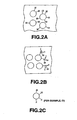
- the kind of fullerene molecule or molecules used as a base material for the fullerene derivative to which proton dissociating groups are introduced is not particularly limited insofar as the fullerene molecules are characterized as a spherical carbon cluster or carbon clusters that generally include the C 36 , C 60 (see Fig. 3A ), C 70 (see Fig. 3B ), C 76 , C 78 , C 80 , C 82 , and C 84 fullerene molecules. It should be noted that a mixture of these fullerene molecules or other like fullerene molecules may also be used as the base material of the fullerene derivative.
- the present invention has uniquely and advantageously examined the proton conductivities of derivatives of these fullerene molecules, and found that a polyhydroxylated fullerene obtained by introducing hydroxyl groups to a number of carbon atoms of a fullerene molecule or molecules exhibits, even in a dry state, a high proton conductivity in a wide temperature range including an ordinary temperature region, that is, a temperature range from less than the freezing point of water to more than the boiling point of water (at least -40AC to 160°C), and further found that the proton conductivity becomes higher when hydrogensulfate ester groups, namely, -OSO 3 H groups, are introduced, in place of the hydroxyl groups, to the fullerene molecule or molecules.
- the polyhydroxylated fullerene or fullerenol is a generic name of a fullerene-based compound that has a structure in which a plurality of hydroxyl groups are added to the fullerene molecule or molecules as shown in Figs. 1A and 1B .
- a plurality of hydroxyl groups are added to the fullerene molecule or molecules as shown in Figs. 1A and 1B .
- some variations can be considered.
- the first synthesis example of the polyhydroxylated fullerene has been reported by Chiang, et al. in 1992. ( L. Y. Chiang, J. W. Swirczewski, C. S. Hsu, S. K. Chowdhury, S. Cameron and K. Creengan, J.
- a fullerene derivative can be formed from an aggregate of the polyhydroxylated fullerene molecules, as schematically shown in Fig. 2A , in which the hydroxyl groups of each of these molecules adjacent to each other (in the figure, ⁇ designates the polyhydroxylated fullerene molecule) act on each other, thereby exhibiting a high proton conductivity (that is, a high transferability of H + between the phenolic hydroxyl groups of the polyhydroxylated fullerene molecule or molecules) within the bulk or aggregate of the polyhydroxylated fullerene molecules.
- the aggregate of fullerene molecules wherein each or a number of the molecules have a plurality of -OSO 3 H groups may be used in place of the aggregate of polyhydroxylated fullerene molecules as previously discussed.
- the fullerene-based compound in which the OH groups are replaced with the -OSO 3 H groups as show in Fig. 2B that is, a hydrogensulfate-esterificated fullerenol (polyhydroxyl hydrogen sulfated fullerene) was reported by Chiang, et al. in 1994. ( L. Y. Chiang, L. Y. Wang, J. W. Swirczewski, S. Soled and S. Cameron, J. Org. Chem. 59, 3960 (1994 )).
- the molecules of polyhydroxyl hydrogen sulfated fullerene may contain only the -OSO 3 H groups or contain a number of the -OSO 3 H groups and a number of the hydroxyl groups.
- an aggregate of a large number of fullerene derivative molecules that contain the hydroxyl groups or -OSO 3 H groups or combinations thereof is prepared. Since the protons derived from a large amount of hydroxyl groups or -OSO 3 H groups or combinations thereof that are originally contained in the molecules directly migrate, the proton conductivity of the bulk or aggregate of these fullerene molecules is self-determined without the need of entrapment of hydrogen resulting from steam molecules or protons from an atmosphere and also without the need of supply of water from an external environment, particularly, the need of absorption of water or the like from atmospheric air. In other words, the proton conductivity of the aggregate of the fullerene derivative molecules that contain the functional groups is not limited by the environmental atmosphere.
- the fullerene molecules as the base material of the fullerene derivative particularly have an electrophilic property, which property may allow not only the -OSO 3 H groups having a high acidity but also the hydroxyl groups to largely promote the ionization of hydrogen. This is one of the reasons why the proton conductor of an embodiment of the present invention exhibits an excellent proton conductivity.
- the proton conductor of an embodiment of the present invention since a large amount of hydroxyl groups or -OSO 3 H groups or combinations thereof can be introduced to each or a number of the fullerene molecules of the fullerene derivative, the numerical density of protons related to conductivity per unit volume of the conductor becomes very large. This is another reason why the proton conductor in this embodiment exhibits an effective conductivity.
- the fullerene derivative of the proton conductor in this embodiment are mostly or substantially composed of carbon atoms
- the fullerene derivative is light in weight, not easily decomposed, and relatively pure, that is, relatively free of contaminants that may negatively impact its desirable proton conductivity properties.
- the cost that is required to produce the fullerene derivative has been rapidly lowered. Accordingly, the fullerene derivative may be regarded as a desirable carbonaceous material based on resource, environmental, economic or other desirable considerations as previously discussed.
- the proton dissociating groups are not limited to the hydroxyl or -OSO 3 H functional groups.
- the proton dissociating groups can be expressed by a chemical formula of -XH where X is an arbitrary atom or atomic group having a bivalent bond, and further the group can be expressed by a chemical formula of -OH or -YOH where Y is an arbitrary atom or atomic group having a bivalent bond.
- the proton dissociating groups are preferably at least one of the -OH and -OSO 3 H, and -COOH, -SO 3 H and -OPO(OH) 3 functional groups.
- electron attractive groups such as, nitro groups, carbonyl groups and carboxyl groups, nitrile groups, alkyl halide groups or halogen atoms (fluorine or chlorine atoms) may be preferably introduced together with the proton dissociating groups, to carbon atoms of the fullerene molecule or molecules.
- Fig. 2C shows a fullerene molecule to which Z is introduced in addition to -OH, where Z represents at least one of the -NO 2 , -CN, -F, -Cl,-COOR, -CHO, -COR, -CF 3 , or -SO 3 CF 3 (R is an alkyl group) electron attractive groups.
- the number of the proton dissociating groups can be freely selected insofar as it is less than the number of the carbon atoms of the fullerene molecule or molecules, and preferably may include 5 functional groups or more.
- the number of functional groups is more preferably half or less than half of the number of carbon atoms of a fullerene molecule or molecules.
- desired proton dissociating groups may be introduced to carbon atoms of each or a number of the fullerene molecules of the fullerene derivative by subjecting a powder of the fullerene molecules to known treatments, such as, acid treatment and hydrolysis suitably in combination.
- the powder of the fullerene derivative thus obtained can be compacted into a desired shape, for example, into a pellet.
- the compacting of the powder can be performed without use of any binder, which is effective to enhance the proton conductivity and to reduce the weight of the proton conductor, resulting in a molded material that substantially contains the fullerene derivative.
- the proton conductor in this embodiment can be suitably used for various electrochemical devices.
- the present invention can be preferably applied to an electrochemical device having a basic structure that includes first and second electrodes and a proton conductor held therebetween, wherein the proton conductor is configured as the proton conductor in this embodiment.
- the proton conductor in this embodiment can be preferably applied to an electrochemical device in which at least one of the first and second electrodes is a gas electrode, or an electrochemical device in which at least one of the first and second electrodes is an active electrode.
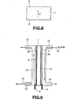
- Fig. 8 is a schematic view showing the proton conductance of the fuel cell in which a proton conducting portion 1 is held between a first electrode (for example, hydrogen electrode) 1 and a second electrode (for example, oxygen electrode) 3, wherein protons dissociated or transferred in the proton conducting portion 1 migrate from the first electrode 2 side to the second electrode 3 side along the direction shown by an arrow in Fig. 8 .
- first electrode for example, hydrogen electrode
- second electrode for example, oxygen electrode
- Fig. 9 is a schematic view showing one example of the fuel cell using the proton conductor in this embodiment.
- the fuel cell is configured such that a negative electrode (fuel electrode or hydrogen electrode) 2 to or in which a catalyst 2a is closely overlapped or dispersed and which has a terminal 8 faces to a positive electrode (oxygen electrode) 3 to or in which a catalyst 3a is closely overlapped or dispersed and which has a terminal 9, and a proton conducting portion 1 is held therebetween.
- hydrogen is supplied from an inlet 12 on the negative electrode 2 side, and is discharged from an outlet 13 (which is sometimes not provided) on the negative electrode 2 side.
- fuel (H 2 ) 14 passes through a flow passage 15
- protons are generated.
- the protons migrate together with protons generated in the proton conducting portion 1, onto the positive electrode 3 side, and react with oxygen (air) 19, which has been supplied in a flow passage 17 from an inlet 16 and flows toward an outlet 18, to generate a desired electromotive force.
- the proton conductivity becomes higher.
- Another embodiment of the present invention will be described below. Another embodiment is different from the present embodiment in that the above-described fullerene derivative is used in combination with a polymer material. However, the proton conductor of the second embodiment essentially has the same proton conductivity features of the present embodiment.
- a second proton conductor in this embodiment contains the above-described fullerene derivative (into which proton dissociating groups are introduced in carbon atoms constituting fullerene) and a polymer material.
- the polymer material may be one kind or two kinds or more known polymers having a film formation ability.
- the content of the polymer material is generally 50 wt% or less. If the content is more than 50 wt%, the proton conductivity of the fullerene derivative may degrade.
- the second proton conductor in this embodiment contains the fullerene derivative, it can exhibit a proton conductivity comparable to that of the proton conductor of the present embodiment.
- the second proton conductor in this embodiment having a film formation ability derived from the polymer material can be used as a flexible proton conductive thin film having a large strength and a gas impermeable property.
- the thickness of the proton conductive thin film is 300 ⁇ m or less.
- the kind of polymer material is not particularly limited insofar as it does not obstruct the proton conductivity as much as possible (due to the reaction with the fullerene derivative or the like) and has a film formation ability, but may be generally selected from polymers having no electronic conductivity and exhibiting a good stability.
- these polymers may include polyfluorethylene, polyvinylidene fluoride, and polyvinyl alcohol. The reason why polyfluorethylene, polyvinylidene fluoride or polyvinyl alcohol are suitable for the second proton conductor in this embodiment will be described below.
- polyfluorethylene is suitable for the second proton conductor. Even by adding polyfluorethylene to the fullerene derivative in an amount smaller than that of another polymer material, it is possible to easily form a thin film of the second proton conductor having a large strength.
- the content of polyfluorethylene includes 3 wt % or less, preferably, in a range of 0.5 to 1.5 wt%. By adding polyfluorethylene to the fullerene derivative in an amount within the above range, the thin film of the second proton conductor has a thickness that ranges from 1 ⁇ m to 100 ⁇ m.
- polyvinylidene fluoride or polyvinyl alcohol are suitable for the second proton conductor is that it is effective to form a proton conductive thin film having a good gas permeation preventive ability.
- the content of these in this case is preferably in the range of 5 to 15 wt%.
- the thin film of the second proton conductor in this embodiment may be obtained by using a known film formation technique, such as, extrusion molding, filtration, application, etc..
- the second proton conductor in this embodiment can be preferably applied to the electrochemical device to which the proton conductor in the present embodiment is applied.
- the proton conductor in the electrochemical device to which the present embodiment is applied, in which the proton conductor is held between the first and second electrodes, the proton conductor may be replaced with the second proton conductor in this embodiment.
- Fig. 10 is a schematic view showing a hydrogen-air cell to which the second proton conductor in this embodiment is applied.
- a hydrogen electrode 21 faces to an air electrode 22 with a proton conductor 20 formed into a thin film (configured as the second proton conductor) held therebetween, and the outsides of these electrodes 21 and 22 are held between a Teflon plate 24a and a Teflon plate 24b having a number of holes 25 and fixed thereto by way of bolts 26a and 26b and nuts 27a and 27b, and a hydrogen electrode reed 28a and an air electrode reed 28b extending from the electrodes 21 and 22 are extracted to the outside of the cell.
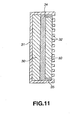
- Fig. 11 is a schematic view showing an electrochemical device to which the second proton conductor in this embodiment is applied.
- a proton conductor 34 (configured as the second proton conductor) is held between a negative electrode 31 having on its inner surface a negative electrode active material layer 30 and a positive electrode (gas electrode) 33 having on its outer surface a gas permeation support 32.
- the negative electrode active material may be configured as a hydrogen absorption alloy or a hydrogen absorption alloy supported by a carbon material such as a fullerene.
- the gas permeation support 32 may be configured as a porous carbon paper.
- the positive electrode 33 may be preferably formed by coating a paste of platinum supported by a powder of carbon. Gaps between the outer ends of the negative electrode 31 and the outer ends of the positive electrode 33 are blocked by gaskets 35. In this electrochemical device, charging can be performed by making water be present on the positive electrode 33 side.
- Fig. 12 is a schematic view showing an electrochemical device to which the second proton conductor in this embodiment is applied.
- a proton conductor 41 formed into a thin film (configured as the second proton conductor) is held between a negative electrode 38 having on its inner surface a negative electrode active material layer 37 and a positive electrode 40 having on its inner surface a positive electrode active material layer 39.
- the positive electrode active material is typically configured as a material essentially comprising nickel hydroxide. Even in this electrochemical device, gaps between the outer ends of the negative electrode 38 and the outer ends of the positive electrode 40 are blocked with gaskets 42.
- Each of the above-described electrochemical devices using the second proton conductor in this embodiment can exhibit a good proton conductive effect on the basis of the same mechanism as that of the electromechanical device using the proton conductor in the present embodiment. Further, since the second proton conductor containing the fullerene derivative in combination with the polymer material having a film formation ability, it can be formed into a thin film having a large strength and a small gas permeability, and therefore, it can exhibit a good proton conductivity.
- the third embodiment is different from the first and second embodiments in that the proton conductor essentially comprises a carbon cluster derivative or derivatives, but is the same or similar to the first and second embodiments in other ways, such as, the basic function of the proton conduction mechanism.
- a third proton conductor in this embodiment essentially comprises a carbon cluster derivative in which the proton dissociating groups are introduced to a number of carbon atoms of each of the clusters or carbon clusters which are used as a base material for the carbon cluster derivative.
- the researches conducted by the present inventor have revealed that, for affording satisfactory proton conductivity to the carbonaceous material, as many proton conduction paths (sites or channels of conduction) as possible need to be provided to the carbonaceous materials. It has been found that satisfactory proton conductivity can be achieved as the entire bulk if a carbon cluster as small in size as possible is used and two or more proton dissociating substituents are introduced on its outer side. In this case, the solid-shaped proton conductor is improved appreciably in acidity.
- the carbon cluster is not deteriorated on oxidation and superior in durability, with the constituent atoms of the carbon cluster being bonded tightly to one another, with the result that the interatomic bond is not collapsed, that is chemical changes are less liable to occur, even if the acidity is high, thus enabling the film structure to be maintained.
- the third proton conductor in this embodiment having the above configuration can exhibit, even in a dry state, a high proton conductivity similar to that of each of the first and second proton conductors in the first and second embodiments.
- the cluster means an aggregate of up to several hundred carbon atoms that are closely bonded together. Due to this aggregated structure, proton conductivity is improved, at the same time as chemical properties are maintained to provide for sufficient film strength and ease with which a layered structure is formed.
- the cluster mainly composed of carbon means an aggregate of up to several hundred carbon atoms that are closely bonded together irrespective of the carbon to carbon molecular-type bonding that exists between the carbon atoms.
- the carbon cluster that is, an aggregate of that substantially contains carbon atoms is not necessarily entirely composed of carbon atoms. In this regard, a collection of atoms, the major part of which is carbon atoms, is herein termed a carbon cluster.
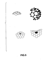
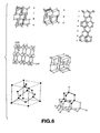
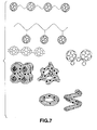
- Fig. 4 to 7 Various types of carbon clusters or aggregates of carbon atoms are shown in Fig. 4 to 7 .
- the proton dissociating groups for example, hydroxyl groups, are not shown. From these figures, it is seen that the materials for the proton conductor permit a wide latitude of selection.
- Fig. 4 shows carbon clusters having spherical structures, spheroid structures, and planar structures similar thereto.
- Fig. 5 shows carbon clusters that have a partially open spherical structure which is characterized by an open end or ends. During production of the fullerene molecules by arc discharge, a large number of carbon clusters having a spherical structure with open ends are generated as sub-products.
- Fig. 6 shows carbon clusters each having a diamond structure, in which most of the carbon atoms of the carbon cluster are in the SP 3 bonding.
- a carbon cluster material in which most of the carbon atoms are in the SP 2 bonding if it has a planar structure of graphite or has all or part of as fullerene or nano-tube structure, is undesirable as the base of the proton conductor because it has often an electronic conductivity due to the SP 2 bonding.
- a fullerene or nano-tube structure that has the SP 2 bonding often has no electronic conductivity because it also partially contains an element that exhibits the desirable SP 3 bonding, and therefore, it is desirable as the base of a proton conductor.
- Fig. 7 shows carbon clusters which are bonded to each other.
- Fig. 7 thus, represents examples of carbon clusters that can be utilized to make the carbon cluster derivative of the proton conductor in an embodiment of the third proton conductor of the present invention.
- the third proton conductor in this embodiment, it is required to introduce proton dissociating groups to the clusters or carbon clusters. Further, it may be desirable to further introduce electronic attractive groups to each of the clusters or carbon cluster.
- the proton dissociating groups may be introduced to each carbon cluster in accordance with the following production method.
- a carbon cluster derivative can be easily obtained by producing carbon clusters composed of carbon powder by arc discharge of a carbon-based electrode, and suitably subjecting the carbon clusters to acid treatment, typically using sulfuric acid and hydrolysis, and also subjected to sulfonation or phosphatation so as to introduce the sulfur and phosphorus-based functional groups, respectively.
- the carbon cluster derivative can be compacted into a suitable shape, for example, into a pellet.
- the length of the major axis of each of the carbon clusters as the base of the carbon cluster derivatives of the proton conductors may be 100 nm or less, preferably, 100 ⁇ or less, and the number of functional groups to be introduced therein may be preferably 2 or more.
- the carbon cluster used for the third proton conductor may be of a cage structure at least part of which has open ends.
- the carbon clusters having such a defect structure has a reactivity similar to that of a fullerene and also has a higher reactivity at its defect portions, that is, its open end portion or portions. Accordingly, the use of carbon clusters each having such a defect structure, that is, open end or ends, as the base of the third proton conductor can promote the introduction of proton dissociating substituents by acid treatment or the like, that is, increase the introduction efficiency of the proton dissociating substituents, thereby enhancing proton conductivity of the third proton conductor. Further, it is possible to synthesize a larger amount of carbon clusters as compared with fullerene molecules, and hence to produce the carbon clusters at a very low cost.
- the kinds of functional groups and the electron attractive groups to be introduced to each of the carbon clusters as the base of the third proton conductor in this embodiment may be the same as those described above.
- the third proton conductor in this embodiment can be suitably applied to various kinds of electrochemical devices, such as, a fuel cell.
- the configuration of the electrochemical device may be basically the same as that of the electromechanical device to which the first or second proton conductor in the first or second embodiment is applied except that the first or second proton conductor is replaced with the third proton conductor. Since the third proton conductor in this embodiment can also exhibit a good proton conductivity even in a dry state, it is possible to eliminate the need of providing any humidifier or other like instrument that produces an external migration, such as, water or steam, and hence to simplify the system configuration and reduce the weight of the system.
- a fourth embodiment of the present invention will be described below in which the proton conductor includes a tubular carbonaceous material derivative.
- the tubular carbonaceous material derivative includes a tubular carbonaceous material as its base material.
- the tubular carbonaceous material includes a CNT material that is composed of nano-tube molecules that each have a diameter of about several nanometers or less, typically, in a range of 1 to 2 nanometers.
- the tubular carbonaceous material includes a CNF material that is composed of nano-fiber molecules which each have a diameter of several nano-meters or more which may reach up to 1 mm.
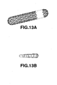
- the CNT material includes a single-wall carbon nano-tube (SWCNT) material that is composed of nano-tube molecules each being formed by a single layer or a multi-wall carbon nano-tube (MWCNT) that is composed of nano-tube molecules that are each formed of two or more layers which are concentrically overlapped.
- SWCNT single-wall carbon nano-tube
- MWCNT multi-wall carbon nano-tube
- the configurations of the SWCNT and the MWCNT molecules are respectively shown in Figs. 13A and 13B .
- the description of the CNT, the SWCNT and MWCNT materials are illustrative only wherein it is understood that the present invention is not limited to the same.
- the proton dissociating groups that are introduced to the tubular carbonaceous materials in order to form the tubular carbonaceous material derivatives include the same proton dissociating groups as previously discussed in regards to the other embodiment of the present invention.
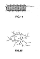
- Fig. 14 shows an example of a tubular carbonaceous material derivative that contains the hydroxyl functional groups.
- Fig. 15 illustrates a number of the tubular carbonaceous molecules or tubular molecules of the tubular carbonaceous material derivative as shown in Fig. 14 .
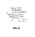
- Fig. 16 illustrates the tubular molecules of another tubular carbonaceous material derivative that includes the -OSO 3 H functional groups.
- Such a tubular carbonaceous material derivative is produced by preparing a halogenated tubular carbonaceous material and subjecting the halogenated material to acid treatment by using sulfuric or nitric acid in order to introduce the -OSO 3 H functional groups to the tubular carbonaceous material so as to form its derivative.
- a hydrolysis technique may be used to introduce hydroxyl groups instead of the -OSO 3 H functional groups. If hydrolysis is used, an acid treatment may follow in order to substitute the hydroxyl groups for different functional groups, such as, the -OSO 3 H functional groups.
- a non-halogenated tubular carbonaceous material is used as a base or raw material so as to form the tubular carbonaceous material derivative, this material may be subjected to acid treatment by using sulfuric or nitric acid as previously discussed. With regards to the halogenated tubular carbonaceous material, fluorine is preferably used.
- the tubular carbonaceous material derivative can be produced not only by the above described wet method but also by the following dry method that utilizes plasma.
- a non-halogenated tubular carbonaceous material is subjected to plasma treatment in an oxygen gas and then subjected to further plasma treatment under a hydrogen gas in order to introduce the proton dissociating groups, typically, hydroxyl groups to the tubular molecules of the tubular carbonaceous material.
- the invention has examined the proton conductivities of these tubular carbonaceous material derivatives and found that these materials provided a high proton conductivity under a varying temperature range that includes the ordinary temperature region, that is, a temperature ranging from less than the freezing point of water to more than the boiling point of water (at least -40°C to 160°C.
- the present invention has further discovered that the proton conductivity is higher for tubular carbonaceous material derivatives that include the hydrogen sulfate as their groups in place of the hydroxyl groups.
- the polyhydroxylated SWCNT material is a generic name of a derivative that has a structure in which a plurality of hydroxyl groups are added to a number of tubular molecules so as to form the SWCNT material as illustrated in Fig. 14 .
- a plurality of hydroxyl groups are added to a number of tubular molecules so as to form the SWCNT material as illustrated in Fig. 14 .
- some variations are considered to be within the scope of the present invention.
- the present invention has newly discovered that an aggregate of polyhydroxylated tubular molecules, namely, a polyhydroxylated SWCNT material, as illustrated in Figs.
- hydroxyl groups of the tubular molecules adjacent to each other act on each other to exhibit a high proton conductivity, that is, a high transfer or migration ability of H + or hydrogen protons from the phenolic hydroxy groups that are contained in each of the tubular molecules of the polyhydroxylated SWCNT material or bulk material.
- the object of the present invention may also be achieved by a proton conductor mainly composed of an aggregate mass of a derivative of a carbonaceous tubular material having plural -OSO 3 H groups, such as an aggregate mass of SWCNT having plural -OSO 3 H groups.
- a proton conductor mainly composed of an aggregate mass of a derivative of a carbonaceous tubular material having plural -OSO 3 H groups, such as an aggregate mass of SWCNT having plural -OSO 3 H groups.
- hydrogen sulfate ester SWCNT in which OSO 3 H groups are substituted for OSO 3 H groups, may contain only OSO 3 H groups, as shown in Fig.16 , or may simultaneously contain plural hydroxy groups and plural OSO 3 H groups in one molecule.
- the proton conductivity of the tubular carbonaceous material derivative that includes an aggregate of the tubular molecules having a number of functional groups is not limited by the environmental surroundings. In this way, an additional source of protons from migrating mediums, such as, water is not necessary in order to realize the desirable effects of the present invention.
- the reason why the tubular carbonaceous material derivative can exhibit such a desirable proton conductivity effect is that a large amount of the functional groups can be introduced to a number of the tubular molecules of the tubular carbonaceous material so that the proton density which corresponds to the conductivity per unit volume of the conductor is very large in size.
- tubular carbonaceous material derivative is mostly composed of carbon atoms of each of the tubular molecules and therefore is light in weight and does not decompose as readily nor contain any contaminants.
- the tubular carbonaceous material that is used for a base material for producing the derivative thereof can be produced by catalytic thermal decomposition of hydrocarbons at a low cost.
- the tubular carbonaceous material is regarded as a material that is desirable for reasons of resource, environment and economy. ( Carbon Vol. 36, No. 11, pp. 1603-1612, 1998 ).
- the proton dissociating groups are not limited to the hydroxyl or -OSO 3 H functional groups as long as they present preferable proton conductivity.
- the proton dissociating groups can be expressed by a chemical formula of -XH where X is an arbitrary atom or atomic group having a bivalent bond, and further the group can be expressed by a chemical formula of -OH or -YOH where Y is an arbitrary atom or atomic group having a bivalent bond.
- the proton dissociating groups are preferably at least one of the -OH and -OSO 3 H, and -COOH, -SO 3 H and -OPO(OH) 3 functional groups.
- the proton dissociating groups to be introduced into these derivatives are arranged in a similar manner as in the aforementioned examples.
- electron attractive groups such as, nitro groups, carbonyl groups and carboxyl groups, nitrile groups, alkyl halide groups or halogen atoms (fluorine or chlorine atoms) may be preferably introduced together with the proton dissociating groups, to carbon atoms of the tubular carbonaceous material.
- the -NO 2 , -CN, -F, -Cl,-COOR, -CHO, -COR, -CF 3 , or -SO 3 CF 3 (R is an alkyl group) electron attractive groups can be introduced to SWCNT, as well as the proton dissociating groups such as OH groups.
- the number is limited to the extent that it is less than the number of carbon atoms of the tubular carbonaceous material derivative.
- the number of functional groups may be limited to the extent that is necessary to cancel the electronic conductivity.
- this number is preferably one or more per ten carbon atoms for a SWCNT material.
- the proton conductor of the present embodiment is mainly composed of the above-mentioned carbonaceous tubular material and may contain other ingredients which are not obstructive to or raise the proton conductivity. Most preferred among these other ingredients is the fullerene derivative having introduced therein the aforementioned proton dissociating groups.
- tubular carbonaceous material derivatives may be desirably formed as a film to be used for an electrochemical device such as a fuel cell.
- These materials can be formed as a film by a known extrusion molding technique and more preferably by dispersing the tubular carbonaceous material derivative in a liquid and filtering the dispersion.
- a solvent such as water is generally used as the liquid.
- the liquid is not particularly limited insofar as the derivative can be dispersed in the liquid.
- the tubular carbonaceous material derivative is deposited in a film shape on the filter.
- the film does not contain any binder and is composed of only the tubular carbonaceous material derivative wherein the tubular molecules are entangled in complicated form.
- Such a film has a very high strength and can be easily peeled from the filter.
- the proton conductor of this embodiment is preferably used for a fuel cell.
- the structure of the fuel cell is as shown in Fig.9 .
- the reactant was put little by little in diethyl ether anhydride cooled in an ice bath, and the deposit was fractionated by centrifugal separation, cleansed twice by diethyl ether and twice by a mixture of diethyl ether and acetonitrile at a mixing ratio of 2 : 1, and dried under a reduced pressure at 40°C.
- the deposit thus cleaned and dried was put into 60 ml of ion exchange water, and stirred for 10 hours at 85°C while being subjected to bubbling using nitrogen.
- the reactant was subjected to centrifugal separation, to separate a deposit, and the deposit was cleaned several times by pure water, repeatedly subjected to centrifugal separation, and dried under a reduced pressure at 40°C.
- both sides of the pellet were held between aluminum plates each having the same diameter as that of the pellet, that is, 15 mm, and AC voltages (amplitude: 0.1 V) at frequencies ranging from 7 MHz to 0.01 Hz are applied to the pellet, to measure a complex impedance at each frequency.
- the measurement was performed under a dry atmosphere.
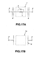
- a proton conducting portion 1 of a proton conductor composed of the above pellet electrically constitutes an equivalent circuit shown in Fig. 17A , in which capacitances 6 and 6' are formed between first and second electrodes 2 and 3 with the proton conducting portion 1 expressed by a parallel circuit of a resistance 4 and a capacitance 5 held therebetween.
- the capacitance 5 designates a delay effect (phase delay at a high frequency) upon migration of protons
- the resistance 4 designates a parameter of difficulty of migration of protons.
- the frequency dependency on the proton conducting portion expressed by the above equivalent circuit was examined.
- Fig. 17B shows an equivalent circuit of a proton conductor (Comparative Example 1 described above) using the typical fullerene molecules without functional groups.
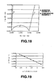
- Fig. 18 shows results of measuring the impedances of the pellets of Inventive Example 1 and Comparative Example 1.
- the frequency characteristics of the complex impedance is nearly the same as the behavior of a single capacitor, and the conductance of charged particles (electrons, ions and the like) of the aggregate of the fullerene molecules is not observed at all; while, for Inventive example 1, the impedance in a high frequency region depicts a flattened but very smooth single semi-circular arc, which shows the conductance of some charged particles in the pellet, and the imaginary number portion of the impedance is rapidly raised in a low frequency region, which shows the occurrence of blocking of charged particles between the aluminum electrode and the pellet as gradually nearing the DC voltage.
- the charged particles on the aluminum electrode side are electrons, and accordingly, it is apparent that the charged particles in the pellets are not electrons or holes but ions, more specifically, protons in consideration of the configuration of the fullerene derivative.
- the conductivity of the above-described charged particles can be calculated on the basis of an intercept of the circular-arc on the high frequency side with the X-axis.
- the conductivity of the charged particles becomes about 5. 10 -6 S/cm.
- the pellets of Inventive Examples 2 and 3 were subjected to the same measurement as described above. As a result, the whole shape in each of the frequency characteristic of the impedance in each of the Inventive Examples 2 and 3 is similar to that in Inventive Example 1; however, as shown in Table 1, the conductivity of charged particles in each of Inventive examples 2 and 3, obtained on the basis of an intercept of a circular-arc portion with the X-axis, is different than in Inventive Example 1.
- the conductivity of the pellet of the fullerene derivative containing the -OSO 3 H groups cause ionization of hydrogen easier than the hydroxyl groups.
- the results of Table 1 also show that the aggregate of the fullerene derivative containing the hydroxyl groups and OSO 3 H groups can exhibit, in a dry atmosphere, a good proton conductivity at ordinary temperature.
- the complex impedance of the pellet produced in Inventive Example 1 was measured in a temperature range from 160°C to -40°C, and the conductivity of the pellet was calculated on the basis of a circular-arc portion on the high frequency side of the complex impedance curve of the pellet measured at each temperature to examine the temperature dependency on the conductivity.
- Fig. 19 the Arrhenius plot
- data of Fig. 19 shows that a single ion conduction mechanism can occur at least within the temperature range of 160°C to -40°C.
- the proton conductor essentially comprising the fullerene derivative according to the present invention therefore, can exhibit a good proton conductivity in a wide temperature range from -40°C to 120°C that includes ordinary temperatures.
- a film of the polyhydroxylated fullerene was formed by the steps of: masking the surface of the electrode by a plastic mask having a rectangular opening, dripping the above-described solution in the opening, spreading the solution in the opening, drying in a room temperature in order to vaporize THF, and removing the mask. The same amount of electrode described above, with its downward surface having a catalyst, was laid on the film.
- the upper electrode was pressed by about 5 tons/cm 2 to complete a composite.
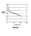
- This composite was incorporated in a fuel cell as shown in Fig. 9 .
- a generating electricity experiment was performed by supplying hydrogen gas to one electrode and air to another electrode in the fuel cell.
- the experimental result is shown in Fig. 20 .
- the open circuit voltage was about 1.2V, and the characteristic of the closed circuit voltage was also excellent against the current value for the fuel cell.
- the IR spectrum of the powder nearly conformed to that of a fullerene derivative in which the hydroxyl groups were all hydrogen sulfate groups shown in the document, and therefore, it was confirmed that the powder was the hydrogen sulfated fullerene as the target material.
- the IR spectrum of the powder nearly conformed to that of a fullerene derivative containing the hydroxyl groups and OSO 3 H groups shown in the document, and therefore, it was confirmed that the powder was the polyhydroxyl hydrogen sulfated fullerene as the target material.
- both sides of the pellet were held between aluminum plates each having the same diameter as that of the pellet, that is, 15 mm, and AC voltages (amplitude: 0.1 V) at frequencies ranging from 7 MHz to 0.01 Hz are applied to the pellet, to measure a complex impedance at each frequency.
- the measurement was performed under a dry atmosphere.
- a proton conducting portion 1 of a proton conductor composed of the above pellet electrically constitutes an equivalent circuit shown in Fig. 17A , in which capacitances 6 and 6' are formed between first and second electrodes 2 and 3 with the proton conducting portion 1 expressed by a parallel circuit of a resistance 4 and a capacitance 5 held therebetween.
- the capacitance 5 designates a delay effect (phase delay at a high frequency) upon migration of protons
- the resistance 4 designates a parameter of difficulty of migration of protons.
- Fig. 17B shows an equivalent circuit of a proton conductor (Comparative Example to be described later) using the typical fullerene molecules that contain no dissociation of proton.
- Fig. 21 shows results of measuring the impedances of the pellet 1A of Inventive Example 4 and the pellet of Comparative Example 2.
- the frequency characteristics of the complex impedance is nearly the same as the behavior of a single capacitor, and the conductance of charged particles (electrons, ions and the like) of the aggregate of the fullerene molecules is not observed at all; while, for the pellet of Inventive Example 4, the impedance in a high frequency region depicts a flattened but very smooth single semi-circular arc, which shows the conductance of some charged particles in the pellet, and the imaginary number portion of the impedance is rapidly raised in a low frequency region, which shows the occurrence of blocking of charged particles between the aluminum electrode and the pellet as gradually nearing the DC voltage.
- the charged particles on the aluminum electrode side are electrons, and accordingly, it is apparent that the charged particles in the pellets are not electrons or holes but ions, more specifically, protons in consideration of the configuration of the fullerene derivative.
- the conductivity of the above-described charged particles can be calculated on the basis of an intercept of the circular-arc on the high frequency side with the X-axis.
- the conductivity of the charged particles become about 1X10 -6 S/cm.
- the pellets of 1B of Inventive Example 4, the pellets of Inventive Example 5, and the pellets of Inventive Example 6 were subjected to the same measurement as described above.
- the whole shape of the frequency characteristics of the impedance in each of the pellets is similar to that of Inventive Example 4; however, as shown in Table 2, the conductivity of charged particles in each of the pellets obtained on the basis of an intercept of a circular-are portion with the X-axis, is different from that in the pellet.
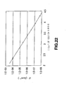
- the complex impedance of the pellet 4A of Inventive Example 4 was measured in a temperature range from 160°C to -40°C, and the conductivity of the pellet was calculated on the basis of a circular-arc portion on the high frequency side of the complex impedance curve of the pellet measured at each temperature to examine the temperature dependency on the conductivity.
- the results are shown in Fig. 22 as the Arrhenius plot. From the data shown in Fig. 22 , it is apparent that the conductivity and temperature exist in a linear relationship at least within the temperature range of 160°C to -40°C. In other words, data of Fig. 22 shows that a single ion conduction mechanism can proceed in the temperature range of 160°C to -40°C.
- the second proton conductor essentially comprising the fullerene derivative and a polymer material according to the present invention therefore, can exhibit a good proton conductivity in a wide temperature range including ordinary temperature, particularly, ranging from a high temperature of 160°C to a low temperature of -40°C.
- Arc discharge was performed by applying a current of 200 A between both electrodes composed of carbon bars in 0.05 MPa of an argon, to thus obtain 1 g of a carbon powder.
- the carbon powder was mixed with 100 ml of 60% fuming sulfuric acid, and kept for three days in a nitrogen flow at 60°C.
- the heating was performed by using a water bath.
- the reaction solution was dropped little by little in 500 ml of pure water, and a solid matter was separated from the water solution by centrifugal separation method.
- the solid matter was cleaned several times by diethyl ether anhydride, and dried for five hours under a reduced pressure at 40°C.
- the resultant powder was dissolved in 10 ml of tetrahydrofurane (THF), an insoluble component removed by filtering, and the solvent was evaporated under a reduced pressure to obtain a solid matter wherein the solid matter of 50 mg was pressed at a force of 5 tons/cm 2 into a circular pellet having a diameter of 15 mm. Such a pellet is taken as a pellet of Inventive Example 7.
- THF tetrahydrofurane
- the AC impedance of the pellet of Inventive Example 7 was measured in a dry air in accordance with the same manner as described above. As a result, it was confirmed that an impedance behavior resulting from ion conductance appeared in a frequency region of 10 MHz or less.
- the conductivity of the pellet of Inventive Example 7 was calculated, on the basis of the diameter of a circular-arc curve of the impedance behavior, at 3.0X10 -4 (S/cm).
- Arc discharge was performed by applying a current of 200 ⁇ between both electrodes composed of carbon bars in 0.05 MPa of an argon gas, to thus obtain 1 g of a carbon powder.
- the carbon powder was dissolved in toluene, an insoluble component was removed by filtering, and the solvent was evaporated under a reduced pressure to obtain a powder again.
- the resultant powder was mixed with 100 ml of 60% fuming sulfuric acid, and kept for three days under a nitrogen flow at 60°C.
- the heating was performed by using a water bath.
- the reaction solution was dropped little by little in 500 ml of pure water, and a solid matter was separated from the water solution by centrifugal separation method.
- the solid matter was cleaned several times by diethyl ether anhydride, and dried for five hours under a reduced pressure at 40°C.
- the solid matter of 50 mg was under a force of 7tons/ into a circular pellet of Inventive Example 8.
- the AC impedance of the pellet of Inventive Example 8 was measured in a dry air in accordance with the same manner as described above. As a result, it was confirmed that an impedance behavior resulting from ion conductance appeared in a frequency region of 10 MHz or less.
- the conductivity of the pellet of Inventive Example 8 was calculated, on the basis of the diameter of a circular-arc curve of the impedance behavior, at 3.4 ⁇ 10 -4 (S/cm).
- the main component of the carbon powder obtained by arc discharge was carbon clusters or molecules of carbon clusters not having a closed structure, such as, a cage structure, but having a structure at least part of which has open ends.
- molecules having a structure with a good electronic conductivity, similar to the graphite structure, which are slightly contained in the carbon cluster molecules obstruct the function of the ionic treatment in Inventive Example 7 and directly after arc discharge in Inventive Example 8.
- Fig. 23 shows the TOF-MS spectrum of [a] carbon powder obtained by arc discharge. As shown in Fig.
- most of the carbon powder has a mass number of 5500 or less, that is, the carbon number of 500 or less. Since the carbon-carbon bonding distance of the carbon powder is less than 2 ⁇ , the diameter of each of the carbon clusters of the powder is less than 100 nm.
- a refined SWCNT material was prepared and then burned for ten hours at 250°C under a fluorine gas in order to obtain polyfluorinated SWCNT.
- the polyfluorinated SWCNT was placed in pure water and refluxed for three days at 100°C while being strongly stirred in order to substitute the fluorine atoms for hydroxyl groups thereby resulting in the polyhydroxylated SWCNT material which is identified as a material in Inventive Example 9.
- Polyhydroxylated SWCNT produced in the same manner as that in Inventive Example 9 was placed in fuming sulfuric acid and stirred for three days at 60°C in order to replace the hydroxyl groups with the OSO 3 H groups thereby resulting in the hydrogen sulfated SWCNT material as identified in Inventive Example 10.
- a refined SWCNT material was prepared and then subjected to oxygen plasma treatment. Then, the atmosphere in the chamber was replaced with hydrogen and the material was subsequently subjected to hydrogen plasma treatment in order to obtain the polyhydroxylated SWCNT material as identified as Inventive Example 11.
- Each of the above three materials was dispersed in water and the dispersion was filtered on a filter paper having pores of 0.2 ⁇ m by suction in order to deposit the film on the filter paper.
- the amount of the dispersion to be filtered was adjusted to form the film having a thickness of 100 ⁇ m.
- both sides of the film were held between aluminum foils which were cut into a disc shape having a diameter 15 mm.
- the disc was held between electrodes, and AC voltages (amplitude: 0.1 V) at frequencies ranging from 7 MHz to 0.01 Hz were applied to the film to measure a complex impedance at each frequency.
- the measurement was performed under a dry atmosphere.
- the measurement result of the film in Comparative Example 4 will be described below.
- the complex impedance of the film was fixed at a low resistance, that is, was not changed over the above frequency range due to the fact that the electronic conductivity of the SWCNT material of Comparative Example 4 is high. As a result, it was revealed that the film in Comparative Example 4 cannot be used as an ionic conductor.
- a complex impedance of the film of Inventive Example 10 is representatively shown in Fig. 24 .
- the impedance in a high frequency region depicts a flattened but very smooth semi-circular curve, which shows the conductance of some charged particles in the film and the imaginary number portion of the impedance is rapidly raised in a low frequency region, which shows the occurrence of the blocking of charged particles between the aluminum electrodes and the film as gradually nearing to a DC voltage.
- the charged particles on the aluminum electrode side are electrons, and accordingly, it is apparent that the charged particles in the film are not electrons or holes but ions, more specifically, protons in considering of the structure of the tubular carbonaceous derivative that forms the film.
- the films in Inventive Examples 9, 11 and 12 the behavior of these films are similar to that of the film in Inventive Example 10 as observed although there was a difference in the size of the circular arc therebetween. Accordingly, it was revealed that the films in Inventive Examples 9 - 12 desirably function as a tubular carbonaceous material derivative of a proton conductor.
- the proton conducting portion 1 of the film-like proton conductor constitutes an electrically equivalent circuit in which a capacitance is formed between first and second electrodes with a resistance in the proton conducting portion held therebetween as similarly identified in the previously discussed embodiments and as further illustrated in Fig. 17A .
- the capacitance designates a delay effect (phase delay at a high frequency) upon migration of protons
- the resistance designates a parameter of difficulty of migration of protons.
- the conductivity of the above described charged particles can be calculated on the basis of an intercept of the circular-arc on the high frequency side of with the X-axis.
- the conductivity of the film in Inventive Example 10 is about 2 ⁇ 10 -5 S/cm.
- the conductivities of the film in other Inventive Examples are different from one another as shown in Table 3.
- Table 3 Conductivities of proton conductor film of present invention (25°C) kind of film Conductivity (S/cm) Film of Inventive Example 9 2 ⁇ 10 -7 Film of Inventive Example 10 2 ⁇ 10 -5 Film of Inventive Example 11 7 ⁇ 10 -8 Film of Inventive Example 12 3 ⁇ 10 -4
Claims (17)
- Elektrochemische Vorrichtung, umfassend eine erste Elektrode, eine zweite Elektrode und einen Protonenleiter, der sich zwischen den ersten und den zweiten Elektroden befindet, wobei der Protonenleiter ein kohlenstoffhaltiges Material umfasst, das ein Fullerenmolekül umfasst, in das protonendissoziierende Gruppen eingeführt sind.
- Elektrochemische Vorrichtung nach Anspruch 1, wobei die Ionenleitfähigkeit des Protonenleiters größer als die Elektronenleitfähigkeit davon ist.
- Elektrochemische Vorrichtung nach Anspruch 1, wobei mindestens ein Teil der Fullerenstruktur offene Enden aufweist.
- Elektrochemische Vorrichtung nach Anspruch 1, wobei die protonendissoziierenden Gruppen durch -XH ausgedrückt sind, wobei X ein beliebiges Atom oder eine Atomgruppe darstellt, die eine bivalente Bindung aufweisen, und wobei H für ein Wasserstoffatom steht.
- Elektrochemische Vorrichtung nach Anspruch 4, wobei die protonendissoziierenden Gruppen durch -OH oder -YOH ausgedrückt sind, wobei Y ein beliebiges Atom oder eine Atomgruppe mit einer bivalenten Bindung ist und wobei O für ein Sauerstoffatom steht.
- Elektrochemische Vorrichtung nach Anspruch 4, wobei die protonendissoziierenden Gruppen aus der Gruppe bestehend aus -OSO3H, -COOH, -SO3H und -OPO(OH)3 ausgewählt sind.
- Elektrochemische Vorrichtung nach Anspruch 1, wobei die protonendissoziierenden Gruppen und elektronenziehende Gruppen in das kohlenstoffhaltige Material eingeführt sind, wobei die elektronenziehenden Gruppen aus der Gruppe bestehend aus Nitrogruppen, Carbonylgruppen, Nitrilgruppen, Alkylhalidgruppen und Halogenatomen ausgewählt ist.
- Elektrochemische Vorrichtung nach Anspruch 1, wobei der Protonenleiter das kohlenstoffhaltige Material, in das die protonendissoziierenden Gruppen eingeführt sind, und ein Polymermaterial umfasst.
- Elektrochemische Vorrichtung nach Anspruch 8, wobei das Polymermateial keine elektrische Leitfähigkeit aufweist.
- Elektrochemische Vorrichtung nach Anspruch 8, wobei das Polymermaterial mindestens eines ist, ausgewählt unter Polyfluorethylen, Polyvinylidenfluorid, und Polyvinylalkohol.
- Elektrochemische Vorrichtung nach Anspruch 8, wobei der Protonenleiter das Polymermaterial in 50 Gew.-% oder weniger umfasst.
- Elektrochemische Vorrichtung nach Anspruch 8, wobei das Polymermaterial Polytetrafluorethylen in 3 Gew.-% oder weniger umfasst.
- Elektrochemische Vorrichtung nach Anspruch 8, die ein dünner Film mit einer Dicke von 300 µm oder weniger ist.
- Elektrochemische Vorrichtung nach Anspruch 1, wobei die erste Elektrode und/oder die zweite Elektrode Gaselektroden sind.
- Elektrochemische Vorrichtung nach Anspruch 1, wobei die erste Elektrode und/oder die zweite Elektrode Elektroden sind, die aktive Materialien umfassen.
- Elektrochemische Vorrichtung nach Anspruch 1, die eine Brennstoffzelle ist.
- Elektrochemische Vorrichtung nach Anspruch 1, die eine Wasserstoff-Luft-Zelle ist.
Applications Claiming Priority (7)
| Application Number | Priority Date | Filing Date | Title |
|---|---|---|---|
| JP20403899 | 1999-07-19 | ||
| JP20403899 | 1999-07-19 | ||
| JP2000058116 | 2000-03-03 | ||
| JP2000058116 | 2000-03-03 | ||
| JP2000157509 | 2000-05-29 | ||
| JP2000157509 | 2000-05-29 | ||
| PCT/JP2000/004864 WO2001006519A1 (fr) | 1999-07-19 | 2000-07-19 | Materiau conducteur de protons, procede de preparation associe, et dispositif electrochimique utilisant ledit materiau |
Publications (3)
| Publication Number | Publication Date |
|---|---|
| EP1205942A1 EP1205942A1 (de) | 2002-05-15 |
| EP1205942A4 EP1205942A4 (de) | 2008-12-17 |
| EP1205942B1 true EP1205942B1 (de) | 2011-01-19 |
Family
ID=27328321
Family Applications (1)
| Application Number | Title | Priority Date | Filing Date |
|---|---|---|---|
| EP00946422A Expired - Lifetime EP1205942B1 (de) | 1999-07-19 | 2000-07-19 | Protonen leitendes material und verfahren zur herstellung desselben, ferner dieses material verwendende, elektrochemische vorrichtung |
Country Status (12)
| Country | Link |
|---|---|
| EP (1) | EP1205942B1 (de) |
| KR (1) | KR100714347B1 (de) |
| CN (1) | CN1225745C (de) |
| AT (1) | ATE496401T1 (de) |
| AU (1) | AU746761B2 (de) |
| BR (1) | BR0012582B1 (de) |
| CA (1) | CA2380120C (de) |
| DE (1) | DE60045554D1 (de) |
| DK (1) | DK1205942T3 (de) |
| IL (1) | IL147699A0 (de) |
| NZ (1) | NZ516548A (de) |
| WO (1) | WO2001006519A1 (de) |
Families Citing this family (35)
| Publication number | Priority date | Publication date | Assignee | Title |
|---|---|---|---|---|
| US7153608B2 (en) | 1999-07-19 | 2006-12-26 | Sony Corporation | Ionic conductor, process for production thereof, and electrochemical device |
| JP4826002B2 (ja) * | 2000-07-28 | 2011-11-30 | ソニー株式会社 | 電気化学デバイス及びその製造方法 |
| JP2002063917A (ja) * | 2000-08-18 | 2002-02-28 | Sony Corp | 電気化学デバイス及びその使用方法 |
| JP4635306B2 (ja) * | 2000-08-18 | 2011-02-23 | ソニー株式会社 | プロトン伝導体及び電気化学デバイス |
| JP4892776B2 (ja) * | 2000-10-20 | 2012-03-07 | ソニー株式会社 | 燃料電池 |
| TW541751B (en) | 2001-01-15 | 2003-07-11 | Sony Corp | Power generator |
| JP2004192808A (ja) * | 2001-01-18 | 2004-07-08 | Sony Corp | プロトン伝導体及びその製造方法、並びに電気化学デバイス |
| JP2002216791A (ja) * | 2001-01-19 | 2002-08-02 | Sony Corp | 燃料電池及び燃料電池モジュール並びにスタック |
| KR20030068584A (ko) * | 2001-01-19 | 2003-08-21 | 소니 가부시키가이샤 | 전극 모듈 |
| WO2002058177A1 (fr) * | 2001-01-19 | 2002-07-25 | Sony Corporation | Film conducteur de protons et son procede de fabrication, cellule a combustible ayant un film conducteur de protons et son procede de fabrication |
| GB2411169B (en) * | 2001-01-29 | 2005-10-26 | Univ Rice William M | Process for derivatizing carbon nanotubes with diazonium species and compositions thereof |
| JP2002246034A (ja) | 2001-02-21 | 2002-08-30 | Sony Corp | ガス拡散性電極体及びその製造方法、並びに電気化学デバイス |
| JP4195299B2 (ja) * | 2001-03-19 | 2008-12-10 | 日本電気株式会社 | 燃料電池用電極及びそれを用いた燃料電池 |
| US7541308B2 (en) | 2001-04-11 | 2009-06-02 | Cabot Corporation | Fuel cells and other products containing modified carbon products |
| JP4715023B2 (ja) * | 2001-05-08 | 2011-07-06 | ソニー株式会社 | フラーレン誘導体の製造方法 |
| JP2003086022A (ja) * | 2001-06-29 | 2003-03-20 | Sony Corp | プロトン伝導体及びこれを用いた電気化学デバイス |
| JP4019313B2 (ja) * | 2001-09-03 | 2007-12-12 | ソニー株式会社 | 電源装置及びその動作方法 |
| JP3951225B2 (ja) * | 2001-10-11 | 2007-08-01 | ソニー株式会社 | プロトン伝導体及びその製造方法、並びに電気化学デバイス |
| JP2003280747A (ja) * | 2002-01-18 | 2003-10-02 | Sony Corp | ガス圧調整装置、電気化学デバイス、気体貯蔵装置及びガス圧調整方法 |
| US6890676B2 (en) | 2002-02-05 | 2005-05-10 | Sony Corporation | Fullerene based proton conductive materials |
| JP4576784B2 (ja) * | 2002-06-03 | 2010-11-10 | ソニー株式会社 | プロトン伝導体膜及びその製造方法、膜−電極接合体及びその製造方法、並びに電気化学デバイス |
| JP4534445B2 (ja) * | 2002-07-19 | 2010-09-01 | ソニー株式会社 | イオン伝導体とその製造方法、並びに電気化学デバイス |
| JP5218467B2 (ja) * | 2002-07-19 | 2013-06-26 | ソニー株式会社 | イオン伝導体とその製造方法、並びに電気化学デバイス |
| JP4320581B2 (ja) | 2003-08-04 | 2009-08-26 | ソニー株式会社 | イオン伝導体、並びに電気化学装置 |
| JP4524579B2 (ja) * | 2003-08-08 | 2010-08-18 | ソニー株式会社 | プロトン伝導性複合体並びに電気化学デバイス |
| KR101063834B1 (ko) | 2003-09-16 | 2011-09-08 | 도오쿄 인스티튜드 오브 테크놀로지 | 술폰산기 도입 무정형 탄소, 그 제조법, 및 그 용도 |
| US7691513B2 (en) * | 2004-04-13 | 2010-04-06 | Panasonic Corporation | Proton conductor, electrolyte membrane, electrode and fuel cell |
| JP5039955B2 (ja) * | 2006-09-07 | 2012-10-03 | トヨタ自動車株式会社 | 燃料電池用電解質および燃料電池 |
| JP5297006B2 (ja) * | 2007-07-09 | 2013-09-25 | 株式会社クレハ | プロトン伝導性樹脂組成物 |
| WO2009101635A1 (en) * | 2008-02-12 | 2009-08-20 | Council Of Scientific & Industrial Research | 'composition with enhanced proton conductivity' |
| JP5604818B2 (ja) * | 2009-07-01 | 2014-10-15 | ソニー株式会社 | イオン伝導性複合体、膜電極接合体(mea)、及び電気化学装置 |
| JP5444904B2 (ja) * | 2009-07-15 | 2014-03-19 | ソニー株式会社 | イオン伝導性微粒子の製造方法 |
| RU2643156C1 (ru) * | 2016-10-21 | 2018-01-31 | МСД Текнолоджис С.а.р.л. | Коаксиальный кабель |
| US9997334B1 (en) * | 2017-02-09 | 2018-06-12 | Lyten, Inc. | Seedless particles with carbon allotropes |
| RU178132U1 (ru) * | 2017-07-12 | 2018-03-26 | МСД Текнолоджис С.а.р.л. | Внешний проводник для электрических кабелей связи коаксиального типа |
Family Cites Families (3)
| Publication number | Priority date | Publication date | Assignee | Title |
|---|---|---|---|---|
| JPH0690881B2 (ja) | 1989-11-27 | 1994-11-14 | 工業技術院長 | 炭素質固体電解質材料およびこれを用いた固体電解質電池 |
| US5177248A (en) * | 1991-10-28 | 1993-01-05 | Exxon Research And Engineering Company | Process of forming polysubstituted fullerenes |
| JP2000256007A (ja) * | 1999-03-11 | 2000-09-19 | Jsr Corp | プロトン伝導性材料の製造方法 |
-
2000
- 2000-07-19 IL IL14769900A patent/IL147699A0/xx not_active IP Right Cessation
- 2000-07-19 AT AT00946422T patent/ATE496401T1/de active
- 2000-07-19 WO PCT/JP2000/004864 patent/WO2001006519A1/ja active IP Right Grant
- 2000-07-19 KR KR1020027000723A patent/KR100714347B1/ko not_active IP Right Cessation
- 2000-07-19 CN CNB008105561A patent/CN1225745C/zh not_active Expired - Fee Related
- 2000-07-19 CA CA2380120A patent/CA2380120C/en not_active Expired - Fee Related
- 2000-07-19 EP EP00946422A patent/EP1205942B1/de not_active Expired - Lifetime
- 2000-07-19 AU AU60216/00A patent/AU746761B2/en not_active Ceased
- 2000-07-19 DK DK00946422.3T patent/DK1205942T3/da active
- 2000-07-19 NZ NZ516548A patent/NZ516548A/xx not_active IP Right Cessation
- 2000-07-19 BR BRPI0012582-2A patent/BR0012582B1/pt not_active IP Right Cessation
- 2000-07-19 DE DE60045554T patent/DE60045554D1/de not_active Expired - Lifetime
Also Published As
| Publication number | Publication date |
|---|---|
| CN1361916A (zh) | 2002-07-31 |
| CA2380120A1 (en) | 2001-01-25 |
| CA2380120C (en) | 2010-10-26 |
| BR0012582B1 (pt) | 2010-08-24 |
| DE60045554D1 (de) | 2011-03-03 |
| KR20020034160A (ko) | 2002-05-08 |
| CN1225745C (zh) | 2005-11-02 |
| EP1205942A1 (de) | 2002-05-15 |
| WO2001006519A1 (fr) | 2001-01-25 |
| NZ516548A (en) | 2004-03-26 |
| DK1205942T3 (da) | 2011-04-18 |
| EP1205942A4 (de) | 2008-12-17 |
| KR100714347B1 (ko) | 2007-05-04 |
| IL147699A0 (en) | 2002-08-14 |
| AU746761B2 (en) | 2002-05-02 |
| BR0012582A (pt) | 2003-07-22 |
| AU6021600A (en) | 2001-02-05 |
| ATE496401T1 (de) | 2011-02-15 |
Similar Documents
| Publication | Publication Date | Title |
|---|---|---|
| EP1205942B1 (de) | Protonen leitendes material und verfahren zur herstellung desselben, ferner dieses material verwendende, elektrochemische vorrichtung | |
| US6821665B2 (en) | Proton conductor, production method thereof, and electrochemical device using the same | |
| KR101183801B1 (ko) | 연료 전지 촉매층의 제조 방법 | |
| CN104022300A (zh) | 固体高分子型燃料电池用膜电极接合体的制造方法 | |
| EP1411568A1 (de) | Protonenleiter und elektrochemische einrichtung damit | |
| JP2007200762A (ja) | 固体高分子形燃料電池用膜電極接合体およびその製造方法 | |
| RU2265257C2 (ru) | Протонный проводник, способ его получения и электрохимическое устройство с его использованием | |
| US7128888B2 (en) | Proton conductor and method for manufacturing the same, and electrochemical device | |
| JP5233153B2 (ja) | 固体高分子形燃料電池用膜電極接合体 | |
| US6824912B2 (en) | Fuel cell and method for preparation thereof | |
| JP4635306B2 (ja) | プロトン伝導体及び電気化学デバイス | |
| US7087340B2 (en) | Proton conducting electrode, method for preparation thereof and electro-chemical device | |
| JP4524579B2 (ja) | プロトン伝導性複合体並びに電気化学デバイス | |
| JP4670219B2 (ja) | プロトン伝導体膜及びその製造方法並びにプロトン伝導体膜を備えた燃料電池及びその製造方法 | |
| JP2002075420A (ja) | 電気化学デバイス及びその駆動方法 | |
| CN101297425A (zh) | 固体高分子型燃料电池用膜电极接合体的制造方法 | |
| JP4475002B2 (ja) | イオン伝導体及びその製造方法、並びに電気化学デバイス | |
| JP2002216796A (ja) | 電気化学デバイス及びプロトン伝導体 | |
| JP2005050628A (ja) | イオン伝導体及びその製造方法、並びに電気化学デバイス | |
| JP2004327205A (ja) | 燃料電池用電極触媒およびその製造方法 |
Legal Events
| Date | Code | Title | Description |
|---|---|---|---|
| PUAI | Public reference made under article 153(3) epc to a published international application that has entered the european phase |
Free format text: ORIGINAL CODE: 0009012 |
|
| 17P | Request for examination filed |
Effective date: 20020115 |
|
| AK | Designated contracting states |
Kind code of ref document: A1 Designated state(s): AT BE CH CY DE DK ES FI FR GB GR IE IT LI LU MC NL PT SE |
|
| AX | Request for extension of the european patent |
Free format text: AL;LT;LV;MK;RO;SI |
|
| A4 | Supplementary search report drawn up and despatched |
Effective date: 20081119 |
|
| RIC1 | Information provided on ipc code assigned before grant |
Ipc: H01M 8/10 20060101AFI20081113BHEP Ipc: H01B 1/12 20060101ALI20081113BHEP |
|
| 17Q | First examination report despatched |
Effective date: 20090226 |
|
| GRAP | Despatch of communication of intention to grant a patent |
Free format text: ORIGINAL CODE: EPIDOSNIGR1 |
|
| GRAS | Grant fee paid |
Free format text: ORIGINAL CODE: EPIDOSNIGR3 |
|
| GRAA | (expected) grant |
Free format text: ORIGINAL CODE: 0009210 |
|
| RIN1 | Information on inventor provided before grant (corrected) |
Inventor name: ROST, CONSTANCESONY CORPORATION Inventor name: HINOKUWA, KOICHIROSONY CORPORATION Inventor name: PIETZAK, BJOERNSONY CORPORATION Inventor name: ATA, MASAFUMISONY CORPORATION |
|
| RIN1 | Information on inventor provided before grant (corrected) |
Inventor name: ATA, MASAFUMISONY CORPORATION Inventor name: ROST, CONSTANCESONY CORPORATION Inventor name: PIETZAK, BJOERNSONY CORPORATION Inventor name: HINOKUMA, KOICHIROSONY CORPORATION |
|
| AK | Designated contracting states |
Kind code of ref document: B1 Designated state(s): AT BE CH CY DE DK ES FI FR GB GR IE IT LI LU MC NL PT SE |
|
| REG | Reference to a national code |
Ref country code: GB Ref legal event code: FG4D |
|
| REG | Reference to a national code |
Ref country code: CH Ref legal event code: EP |
|
| REG | Reference to a national code |
Ref country code: IE Ref legal event code: FG4D |
|
| REG | Reference to a national code |
Ref country code: NL Ref legal event code: T3 |
|
| REF | Corresponds to: |
Ref document number: 60045554 Country of ref document: DE Date of ref document: 20110303 Kind code of ref document: P |
|
| REG | Reference to a national code |
Ref country code: DE Ref legal event code: R096 Ref document number: 60045554 Country of ref document: DE Effective date: 20110303 |
|
| REG | Reference to a national code |
Ref country code: SE Ref legal event code: TRGR |
|
| REG | Reference to a national code |
Ref country code: DK Ref legal event code: T3 |
|
| PG25 | Lapsed in a contracting state [announced via postgrant information from national office to epo] |
Ref country code: GR Free format text: LAPSE BECAUSE OF FAILURE TO SUBMIT A TRANSLATION OF THE DESCRIPTION OR TO PAY THE FEE WITHIN THE PRESCRIBED TIME-LIMIT Effective date: 20110420 Ref country code: PT Free format text: LAPSE BECAUSE OF FAILURE TO SUBMIT A TRANSLATION OF THE DESCRIPTION OR TO PAY THE FEE WITHIN THE PRESCRIBED TIME-LIMIT Effective date: 20110519 Ref country code: ES Free format text: LAPSE BECAUSE OF FAILURE TO SUBMIT A TRANSLATION OF THE DESCRIPTION OR TO PAY THE FEE WITHIN THE PRESCRIBED TIME-LIMIT Effective date: 20110430 |
|
| PG25 | Lapsed in a contracting state [announced via postgrant information from national office to epo] |
Ref country code: BE Free format text: LAPSE BECAUSE OF FAILURE TO SUBMIT A TRANSLATION OF THE DESCRIPTION OR TO PAY THE FEE WITHIN THE PRESCRIBED TIME-LIMIT Effective date: 20110119 Ref country code: CY Free format text: LAPSE BECAUSE OF FAILURE TO SUBMIT A TRANSLATION OF THE DESCRIPTION OR TO PAY THE FEE WITHIN THE PRESCRIBED TIME-LIMIT Effective date: 20110119 |
|
| PGFP | Annual fee paid to national office [announced via postgrant information from national office to epo] |
Ref country code: DK Payment date: 20110720 Year of fee payment: 12 Ref country code: FR Payment date: 20110729 Year of fee payment: 12 |
|
| PLBE | No opposition filed within time limit |
Free format text: ORIGINAL CODE: 0009261 |
|
| STAA | Information on the status of an ep patent application or granted ep patent |
Free format text: STATUS: NO OPPOSITION FILED WITHIN TIME LIMIT |
|
| PGFP | Annual fee paid to national office [announced via postgrant information from national office to epo] |
Ref country code: AT Payment date: 20110714 Year of fee payment: 12 Ref country code: FI Payment date: 20110714 Year of fee payment: 12 Ref country code: SE Payment date: 20110722 Year of fee payment: 12 Ref country code: GB Payment date: 20110721 Year of fee payment: 12 |
|
| 26N | No opposition filed |
Effective date: 20111020 |
|
| PGFP | Annual fee paid to national office [announced via postgrant information from national office to epo] |
Ref country code: IT Payment date: 20110722 Year of fee payment: 12 |
|
| REG | Reference to a national code |
Ref country code: DE Ref legal event code: R097 Ref document number: 60045554 Country of ref document: DE Effective date: 20111020 |
|
| PG25 | Lapsed in a contracting state [announced via postgrant information from national office to epo] |
Ref country code: MC Free format text: LAPSE BECAUSE OF NON-PAYMENT OF DUE FEES Effective date: 20110731 |
|
| REG | Reference to a national code |
Ref country code: CH Ref legal event code: PL |
|
| REG | Reference to a national code |
Ref country code: IE Ref legal event code: MM4A |
|
| PG25 | Lapsed in a contracting state [announced via postgrant information from national office to epo] |
Ref country code: LI Free format text: LAPSE BECAUSE OF NON-PAYMENT OF DUE FEES Effective date: 20110731 Ref country code: CH Free format text: LAPSE BECAUSE OF NON-PAYMENT OF DUE FEES Effective date: 20110731 |
|
| PG25 | Lapsed in a contracting state [announced via postgrant information from national office to epo] |
Ref country code: IE Free format text: LAPSE BECAUSE OF NON-PAYMENT OF DUE FEES Effective date: 20110719 |
|
| REG | Reference to a national code |
Ref country code: DE Ref legal event code: R084 Ref document number: 60045554 Country of ref document: DE Effective date: 20120614 |
|
| PGFP | Annual fee paid to national office [announced via postgrant information from national office to epo] |
Ref country code: NL Payment date: 20120719 Year of fee payment: 13 |
|
| REG | Reference to a national code |
Ref country code: SE Ref legal event code: EUG |
|
| REG | Reference to a national code |
Ref country code: AT Ref legal event code: MM01 Ref document number: 496401 Country of ref document: AT Kind code of ref document: T Effective date: 20120719 |
|
| GBPC | Gb: european patent ceased through non-payment of renewal fee |
Effective date: 20120719 |
|
| REG | Reference to a national code |
Ref country code: DK Ref legal event code: EBP |
|
| REG | Reference to a national code |
Ref country code: FR Ref legal event code: ST Effective date: 20130329 |
|
| PG25 | Lapsed in a contracting state [announced via postgrant information from national office to epo] |
Ref country code: FR Free format text: LAPSE BECAUSE OF NON-PAYMENT OF DUE FEES Effective date: 20120731 Ref country code: SE Free format text: LAPSE BECAUSE OF NON-PAYMENT OF DUE FEES Effective date: 20120720 Ref country code: GB Free format text: LAPSE BECAUSE OF NON-PAYMENT OF DUE FEES Effective date: 20120719 Ref country code: FI Free format text: LAPSE BECAUSE OF NON-PAYMENT OF DUE FEES Effective date: 20120719 |
|
| PG25 | Lapsed in a contracting state [announced via postgrant information from national office to epo] |
Ref country code: IT Free format text: LAPSE BECAUSE OF NON-PAYMENT OF DUE FEES Effective date: 20120719 Ref country code: LU Free format text: LAPSE BECAUSE OF NON-PAYMENT OF DUE FEES Effective date: 20110719 |
|
| PG25 | Lapsed in a contracting state [announced via postgrant information from national office to epo] |
Ref country code: AT Free format text: LAPSE BECAUSE OF NON-PAYMENT OF DUE FEES Effective date: 20120719 |
|
| PG25 | Lapsed in a contracting state [announced via postgrant information from national office to epo] |
Ref country code: DK Free format text: LAPSE BECAUSE OF NON-PAYMENT OF DUE FEES Effective date: 20120731 |
|
| REG | Reference to a national code |
Ref country code: NL Ref legal event code: V1 Effective date: 20140201 |
|
| PG25 | Lapsed in a contracting state [announced via postgrant information from national office to epo] |
Ref country code: NL Free format text: LAPSE BECAUSE OF NON-PAYMENT OF DUE FEES Effective date: 20140201 |
|
| REG | Reference to a national code |
Ref country code: DE Ref legal event code: R082 Ref document number: 60045554 Country of ref document: DE Ref country code: DE Ref legal event code: R081 Ref document number: 60045554 Country of ref document: DE Owner name: MURATA MANUFACTURING CO., LTD., NAGAOKAKYO-SHI, JP Free format text: FORMER OWNER: TOHOKU MURATA MANUFACTURING CO., LTD, KORIYAMA-SHI, JP Ref country code: DE Ref legal event code: R081 Ref document number: 60045554 Country of ref document: DE Owner name: MURATA MANUFACTURING CO., LTD., NAGAOKAKYO-SHI, JP Free format text: FORMER OWNER: SONY CORPORATION, TOKIO/TOKYO, JP |
|
| PGFP | Annual fee paid to national office [announced via postgrant information from national office to epo] |
Ref country code: DE Payment date: 20190719 Year of fee payment: 20 |
|
| REG | Reference to a national code |
Ref country code: DE Ref legal event code: R071 Ref document number: 60045554 Country of ref document: DE |