EP1203595B1 - Méthode de marquage d'objets médicaux allongés et cathéter obtenu ainsi - Google Patents
Méthode de marquage d'objets médicaux allongés et cathéter obtenu ainsi Download PDFInfo
- Publication number
- EP1203595B1 EP1203595B1 EP01125342A EP01125342A EP1203595B1 EP 1203595 B1 EP1203595 B1 EP 1203595B1 EP 01125342 A EP01125342 A EP 01125342A EP 01125342 A EP01125342 A EP 01125342A EP 1203595 B1 EP1203595 B1 EP 1203595B1
- Authority
- EP
- European Patent Office
- Prior art keywords
- color developing
- guide wire
- developing agent
- laser
- catheter
- Prior art date
- Legal status (The legal status is an assumption and is not a legal conclusion. Google has not performed a legal analysis and makes no representation as to the accuracy of the status listed.)
- Expired - Lifetime
Links
Images

Classifications
-
- B—PERFORMING OPERATIONS; TRANSPORTING
- B41—PRINTING; LINING MACHINES; TYPEWRITERS; STAMPS
- B41M—PRINTING, DUPLICATING, MARKING, OR COPYING PROCESSES; COLOUR PRINTING
- B41M5/00—Duplicating or marking methods; Sheet materials for use therein
- B41M5/26—Thermography ; Marking by high energetic means, e.g. laser otherwise than by burning, and characterised by the material used
- B41M5/267—Marking of plastic artifacts, e.g. with laser
-
- A—HUMAN NECESSITIES
- A61—MEDICAL OR VETERINARY SCIENCE; HYGIENE
- A61M—DEVICES FOR INTRODUCING MEDIA INTO, OR ONTO, THE BODY; DEVICES FOR TRANSDUCING BODY MEDIA OR FOR TAKING MEDIA FROM THE BODY; DEVICES FOR PRODUCING OR ENDING SLEEP OR STUPOR
- A61M25/00—Catheters; Hollow probes
-
- A—HUMAN NECESSITIES
- A61—MEDICAL OR VETERINARY SCIENCE; HYGIENE
- A61M—DEVICES FOR INTRODUCING MEDIA INTO, OR ONTO, THE BODY; DEVICES FOR TRANSDUCING BODY MEDIA OR FOR TAKING MEDIA FROM THE BODY; DEVICES FOR PRODUCING OR ENDING SLEEP OR STUPOR
- A61M25/00—Catheters; Hollow probes
- A61M25/01—Introducing, guiding, advancing, emplacing or holding catheters
- A61M25/0105—Steering means as part of the catheter or advancing means; Markers for positioning
- A61M25/0108—Steering means as part of the catheter or advancing means; Markers for positioning using radio-opaque or ultrasound markers
-
- A—HUMAN NECESSITIES
- A61—MEDICAL OR VETERINARY SCIENCE; HYGIENE
- A61M—DEVICES FOR INTRODUCING MEDIA INTO, OR ONTO, THE BODY; DEVICES FOR TRANSDUCING BODY MEDIA OR FOR TAKING MEDIA FROM THE BODY; DEVICES FOR PRODUCING OR ENDING SLEEP OR STUPOR
- A61M25/00—Catheters; Hollow probes
- A61M2025/0008—Catheters; Hollow probes having visible markings on its surface, i.e. visible to the naked eye, for any purpose, e.g. insertion depth markers, rotational markers or identification of type
-
- A—HUMAN NECESSITIES
- A61—MEDICAL OR VETERINARY SCIENCE; HYGIENE
- A61M—DEVICES FOR INTRODUCING MEDIA INTO, OR ONTO, THE BODY; DEVICES FOR TRANSDUCING BODY MEDIA OR FOR TAKING MEDIA FROM THE BODY; DEVICES FOR PRODUCING OR ENDING SLEEP OR STUPOR
- A61M25/00—Catheters; Hollow probes
- A61M25/0043—Catheters; Hollow probes characterised by structural features
- A61M2025/006—Catheters; Hollow probes characterised by structural features having a special surface topography or special surface properties, e.g. roughened or knurled surface
-
- A—HUMAN NECESSITIES
- A61—MEDICAL OR VETERINARY SCIENCE; HYGIENE
- A61M—DEVICES FOR INTRODUCING MEDIA INTO, OR ONTO, THE BODY; DEVICES FOR TRANSDUCING BODY MEDIA OR FOR TAKING MEDIA FROM THE BODY; DEVICES FOR PRODUCING OR ENDING SLEEP OR STUPOR
- A61M25/00—Catheters; Hollow probes
- A61M25/0009—Making of catheters or other medical or surgical tubes
-
- Y—GENERAL TAGGING OF NEW TECHNOLOGICAL DEVELOPMENTS; GENERAL TAGGING OF CROSS-SECTIONAL TECHNOLOGIES SPANNING OVER SEVERAL SECTIONS OF THE IPC; TECHNICAL SUBJECTS COVERED BY FORMER USPC CROSS-REFERENCE ART COLLECTIONS [XRACs] AND DIGESTS
- Y10—TECHNICAL SUBJECTS COVERED BY FORMER USPC
- Y10S—TECHNICAL SUBJECTS COVERED BY FORMER USPC CROSS-REFERENCE ART COLLECTIONS [XRACs] AND DIGESTS
- Y10S430/00—Radiation imagery chemistry: process, composition, or product thereof
- Y10S430/146—Laser beam
Definitions
- the present invention relates to a medical long object having a mark on its surface.
- a guide wire is used.
- the guide wire is inserted to the predetermined position of the biological lumen or the like before guiding the endoscope.
- the guide wire is monochromic, the movement thereof is not recognized even when it is moving in an axial direction. Therefore, it is preferable that a mark representing a position and the like of the guide wire is provided on the surface thereof.
- JP 09-501593 A discloses a method for attaching a hollow tube to a guide wire. According to this method, a hollow tube made of Teflon® or the like and having a plurality of colored streaks is shrunk over a core wire of a guide wire so as to wrap it.
- a mark is provided simultaneously with the formation of the guide wire. Therefore, it is difficult to provide a mark at a desired position. Furthermore, the shape and width of a mark may become uniform as a whole.
- JP 04-108556 U discloses a method for forming a mark by printing.
- ink Since ink has no solvent resistance, it is difficult to provide a lubricating coat such as a hydrophilic polymer to the surface of a guide wire after forming a mark. It is also difficult to conduct marking on a curved surface. A time for drying ink is also required. During use, ink may peel off to flow into a living body.
- a lubricating coat such as a hydrophilic polymer
- JP 06-63054 U discloses a method for providing a transparent coating layer made of fluorine resin after printing a mark.
- USP 4,951,686 discloses a method for heating a site of a catheter guide wire made of steel, in which a color mark is to be formed, at a temperature allowing a temper color to appear.
- a catheter guide wire made of steel can be used. Furthermore, a superelastic alloy (Ni-Ti alloy) generally used as a core wire of a guide wire is likely to have its physical properties changed by heat treatment such as heating. Therefore, this method is not preferable.
- USP 4,951,686 also discloses a method for forming marks by stamping or irradiation with laser light.
- a mark portion to be formed may be raised, and according to the latter method, a mark portion to be formed may be recessed, and thus obtained mark is less visible since the mark has no color change.
- the above-mentioned problems are not limited to guide wires.
- information such as a scale (length from a tip end, etc.) is printed on a surface. Therefore, the catheters also have the same problems as those in the guide wires.
- a superelastic alloy Ni-Ti alloy
- the present invention provides a medical long object including a part formed of a polymeric material containing a laser color developing agent at least in a part of a surface, and a color developing portion formed in the part by color development of the laser color developing agent due to irradiation with laser light.
- the present invention provides a medical long object having a tip end portion and a base end portion, including a polymeric material surface formed of a polymeric material containing a laser color developing agent at least in the tip end portion, and a light developing portion formed by color development of the laser color developing agent due to irradiation with laser light on the polymeric material surface.
- the laser color developing agent contains mica and/or a compound thereof.
- the above-mentioned medical long object is a guide wire.
- the above-mentioned medical long object is a catheter.
- the present invention provides a method for producing a medical long object, including: forming at least a part of a surface of a medical long object with a polymeric material containing a laser color developing agent; and irradiating only a portion of the surface of the medical long object in which a color is to be developed with laser light so as to allow the laser color developing agent to develop a color, thereby forming any pattern on the surface of the medical long object.
- the laser color developing agent is contained 0.01 to 10% by mass on the total amount of the polymeric material component.
- a medical long object of the present invention has a part made of a polymeric material containing a laser color developing agent at least in a part of its surface.
- Examples of a polymeric material used in the present invention include resin, rubber, and the like.
- the resin include polyurethane, polyethylene, polypropylene, an ethylene-propylene copolymer, fluorine resin (e.g., polytetrafluoroethylene), polyethylene terephthalate, polyvinyl chloride, polyamide, polyimide, an ethylene - vinyl acetate copolymer, an ethylene - ethyl acrylate copolymer, silicone, polycarbonate, a styrene - butadiene copolymer, ABS resin, polyisoprene, and polybutadiene.
- polyurethane is preferable.
- a laser color developing agent used in the present invention there is no particular limit to a laser color developing agent used in the present invention, as long as it develops a color by irradiation with laser light. It is preferable that the laser color developing agent contains mica and/or a compound thereof.
- the laser color developing agent containing mica and/or a compound thereof there are the following advantages: a laser color developing agent develops a color sufficiently only by being contained in a polymeric material in a small amount, a color developing portion is hardly raised or recessed, since the content of a laser color developing agent may be small, a change in a color of a non-color developing portion can be suppressed, and the like.
- color development used in the present specification also includes all the perceivable changes in a color such as discoloration, decolorization, and fading in addition to color development.
- Examples of the laser color developing agent containing mica and/or a compound thereof include natural mica such as mica belonging to muscovite series (e.g., muscovite, lepidolite, paragonite, sericite, roscoelite, illite), mica belonging to biotite series (e.g., biotite, phlogopite, lepidolite, zinnwaldite), glauconite, celadonite, muscovite, phlogovite, suzolite, paragonite, and vermiculite; synthetic mica (specifically, Iriodin LS-800 produced by Merck Japan Co., Ltd.
- natural mica such as mica belonging to muscovite series (e.g., muscovite, lepidolite, paragonite, sericite, roscoelite, illite), mica belonging to biotite series (e.g., biotite, phlogopite, lepidolite, zinn
- Iriodin LS-805 produced by Merck Japan Co., Ltd. having a particle diameter of 2 to 100 ⁇ m
- a composition hereinafter, referred to as "Mica composition 1". More specifically, Iriodin LS-820 produced by Merck Japan Co., Ltd. having a particle diameter of 15 ⁇ m or less) composed of mica, titanium oxide, silicon oxide, and tin oxide doped with antimony oxide; a composition (hereinafter, referred to as "Mica composition 2". More specifically, Iriodin LS-825 produced by Merck Japan Co., Ltd.
- Mica composition 3 More specifically, Iriodin LS-810 produced by Merck Japan Co., Ltd. having a particle diameter of 2 to 28 ⁇ m) composed of mica and titanium oxide; a composition (hereinafter, referred to as "Mica composition 4". More specifically, Iriodin LS-830 produced by Merck Japan Co., Ltd. having a particle diameter of 10 to 60 ⁇ m) composed of mica, titanium oxide, and iron oxide; and a composition (hereinafter, referred to as "Mica composition 5". More specifically, Iriodin LS-835 produced by Merck Japan Co., Ltd. having a particle diameter of 15 ⁇ m or less) composed of mica and iron oxide. Of those, Mica compositions 1 and 2 are preferable.
- These laser color developing agents may be used alone or in combination.
- the content of the laser color developing agent in the polymeric material is varied depending upon the kind of the laser color developing agent, the color of the polymeric material, and the like.
- the content of the laser color developing agent is preferably 0.01 to 10% by mass, more preferably 0.1 to 2% by mass based on the total amount of the polymeric material component.
- the color tone after irradiation with laser light can be regulated by the content of the laser color developing agent.
- Mica composition 1 and/or 2 in particular high color development can be obtained with a small content thereof. More specifically, when the mica composition is contained in the polymeric material component in an amount of 0.01 to 2% by mass, more preferably 0.1 to 1% by mass, high color development can be obtained.
- Additives other than the laser color developing agent e.g., a filler, a pigment, a dye, an antiaging agent, an antioxidant, an anti-static agent, a lubricant, a plasticizer, a thermal stabilizer, X-ray contrast medium
- a filler e.g., a filler, a pigment, a dye, an antiaging agent, an antioxidant, an anti-static agent, a lubricant, a plasticizer, a thermal stabilizer, X-ray contrast medium
- the medical long object of the present invention only needs to have a part made of a polymeric material containing a laser color developing agent in any part of the surface.
- the medical long object of the present invention has a tip end portion and a base end portion, it is one preferred embodiment that the above-mentioned part is provided at least in the tip end portion of the surface. If there is a mark in the tip end portion of the surface, it becomes easy to manipulate the medical long object, and information on the length from the tip end and the like can be displayed.
- a medical long object has a tip end portion and a base end portion, the medical long object being characterized by including a polymeric material surface made of a polymeric material containing a laser color developing agent at least in the tip end portion, and has a color developing portion formed by color development of the laser color developing agent due to irradiation with laser light on the polymeric material surface.
- the entire surface of the medical long object or the entire medical long object may be made of a polymeric material containing the above-mentioned laser color developing agent.
- a material of the other part is not particularly limited, and appropriately selected in accordance with the use of the medical long object.
- the surface of the medical long object of the present invention may be coated with a low-friction material, whereby the medical long object has its friction reduced and can be smoothly inserted into a biological lumen or the like, thus operability and safety thereof are enhanced.
- An example of the low-friction material includes a hydrophilic polymer.
- hydrophilic polymer examples include natural polymeric materials (e.g., starches, celluloses, polysaccharides, protein), and synthetic polymeric materials (e.g., PVA, polyethylene oxides, acrylic acids, maleic anhydrides, phthalic acids, water-soluble polyester, (meth)acrylamides, polyamines, water-soluble nylons type).
- natural polymeric materials e.g., starches, celluloses, polysaccharides, protein
- synthetic polymeric materials e.g., PVA, polyethylene oxides, acrylic acids, maleic anhydrides, phthalic acids, water-soluble polyester, (meth)acrylamides, polyamines, water-soluble nylons type.
- cellulose type polymeric materials e.g., hydroxypropylcellulose
- polyethylene oxide type polymeric materials e.g., polyethylene glycol
- maleic anhydride type polymeric materials e.g., maleic anhydride copolymer such as a copolymer of methyl vinyl ether and maleic anhydride
- acrylamide type polymeric materials e.g., polydimethylacrylamide
- water-soluble nylon e.g., AQ-nylon P-70 produced by Toray Industries, Inc.
- the surface of the medical long object of the present invention is coated with a low-friction material
- a low-friction material among the hydrophilic polymers described-above, those which are transparent or semi-transparent are used so that a light developing portion on the surface can be observed from outside even if being coated.
- the medical long object of the present invention has, in a part made of a polymeric material containing a laser color developing agent, a color developing portion formed by color development of the laser color developing agent due to irradiation with laser light.
- Laser light used for irradiation is selected in accordance with a laser color developing agent.
- the laser light include near-infrared laser light such as Nd-YAG laser light, near-infrared laser light such as CO 2 laser light, and excimer laser light.
- the Nd-YAG laser light can be near-infrared ray with a wavelength of 1.06 ⁇ m, which can be obtained by irradiating a YAG (yttrium aluminum garnet) lot with light of an arc lamp.
- YAG yttrium aluminum garnet
- CO 2 laser light is far infrared ray with a wavelength of 10.6 ⁇ m, which can be obtained by applying a high frequency (RF) and a high voltage (TEA) to a tube in which CO 2 mixed gas is filled, thereby exciting the CO 2 mixed gas.
- RF high frequency
- TAA high voltage
- the irradiation amount of laser light is preferably in a range of 1.8 to 2.0 kW as an energy output of an irradiation origin
- Laser is not particularly limited.
- conventionally known laser such as those of scanning type, dot type, and mask type can be used.
- laser light emitted from an oscillator is scanned in an X-Y direction by two rotation mirrors, and then condensed with a lens, and radiated.
- laser light is radiated while a medical long object is allowed to stand still, so that marking with any shape can be conducted.
- laser light is tuned to a polygon mirror rotated at a high speed, and is radiated. High-speed marking can be conducted.
- laser light passes through a patterned mask (stencil) and a condensing lens to be radiated.
- a patterned mask stencil
- a condensing lens to be radiated.
- High-speed marking and marking with a fine pattern can be conducted.
- These lasers can be appropriately selected in accordance with the use and the like of a medical long object.
- a laser color developing agent contained in a polymeric material develops a color to form a color developing portion. Because of this, the surface of the medical long object can be provided with a mark. For example, a plurality of marks can be formed at desired positions over the length by irradiation with laser light.
- Examples of a mark include a letter, a number, a pattern, a design, and the like. By selecting a laser color developing agent, a mark can be formed in monochrome or color.
- the size, shape, and the like of the medical long object of the present invention can be appropriately determined in accordance with the use and purpose.
- the medical long object of the present invention can be used, for example, as a guide wire and a catheter.
- a guide wire and a catheter have a curved surface. Therefore, it is difficult to apply the conventional method for forming a mark to a guide wire and a catheter. Therefore, a guide wire and a catheter are included in one preferred embodiment of the medical long object of the present invention.
- the medical long object of the present invention is a guide wire.
- the guide wire of the present invention has a part made of a polymeric material containing a laser color developing agent at least in a part of the surface thereof, and has a color developing portion formed in the part by color development of the laser color developing agent due to irradiation with laser light, there is no particular limit to the guide wire, and a known shape, structure, and the like can be adopted.
- a core wire used in the guide wire of the present invention is a line material having flexibility.
- a constituent material for the core wire is not particularly limited, and various plastics and various metals can be used. However, it is preferable that the core wire is made of a superelastic alloy. Because of this, a guide wire excellent in torque transferability and kink (bending) resistance can be obtained without increasing the diameter of the guide wire.
- a superelastic alloy is generally called a shape-memory alloy, which refers to an alloy exhibiting superelasticity at a service temperature.
- Superelasticity refers to a property of metal in which even if ordinary metal is deformed (bent, pulled, compressed) to plastic deformation at a service temperature, i.e., at least a temperature of a living body (in the vicinity of 37°C), the metal is restored to substantially the original shape.
- Examples of a preferable composition of a superelastic alloy include superelastic body such as a Ti-Ni alloy containing 49 to 58% by atom of Ni, a Cu-Zn alloy containing 38.5 to 41.5% by mass of Zn, a Cu-Zn-X alloy (where X is at least one selected from Be, Si, Sn, Al, and Ga) containing 1 to 10% by mass of X, and an Ni-Al alloy containing 36 to 38% by atom of Al.
- the Ti-Ni alloy is preferable.
- the diameter of a core wire used in the guide wire of the present invention is preferably in a range of 0.25 to 1.57 mm, more preferably in a range of 0.4 to 0.97 mm.
- the tip end portion of the core wire is tapered in accordance with characteristics such as touch resistance, bend resistance, and the like, and its outer diameter is gradually reduced toward the tip end. Because of this, when the guide wire is inserted into a biological lumen or the like from the tip end side so as to reach an intended site (lesion), when the guide wire can flexibly follow a complicated shape such as a curve and a branch of the biological lumen, whereby the guide wire can be easily and safely inserted into and removed from the lumen.
- the guide wire of the present invention is obtained by coating at least a part of the surface of the above-mentioned core wire with a polymeric material containing a laser color developing agent.
- the thickness of a coating layer is not particularly limited, it is preferably 0.05 to 0.3 mm on the average, more preferably 0.1 to 0.2 mm on the average.
- the thickness of the coating layer may be uniform over the entire layer or may be varied depending upon a site. For example, it may have taken structure that the thickness of the coating layer may be increased in the vicinity of the tip end portion of the guide wire.
- the number of coating layers is not limited to one, and a plurality of stacked coating layers may be used.
- the guide wire is generally used to be inserted into and held in a living body under X-ray fluoroscopy. Therefore, it is preferable that the guide wire body is provided with an X-ray contrast property. That is, it is preferable that an X-ray contrast medium is contained in a constituent material of the guide wire body.
- the X-ray contrast medium include metal or a metal compound such as platinum, silver, tungsten, barium sulfate, and bismuth oxide.
- the medical long object of the present invention is a catheter.
- the catheter of the present invention has a part made of a polymeric material containing a laser color developing agent at least in a part of the surface thereof, and has a color developing portion formed in the part by color development of the laser color developing agent due to irradiation with laser light, there is no particular limit to the catheter, and a known shape, structure, and the like can be adopted.
- the catheter of the present invention has a part made of a polymeric material containing a laser color developing agent at least in a part of the surface thereof, the other part may be made of a material with flexibility, such as polyvinyl chloride, polyurethane, polyethylene, polypropylene, polyamide, polytetrafluoroethylene, silicone rubber, and an ethylene - vinyl acetate copolymer.
- the polymeric material used in a part made of a polymeric material containing a laser color developing agent may be the same as or different from the polymeric material used in the other part.
- a reinforcing member made of a polymeric material (e.g., hard polyurethane and polyimide) or metal (e.g., a coil spring) in a part of the catheter body except for the tip end portion, the stiffness of the part of the catheter body excluding the tip end portion can be enhanced compared with that of the tip end portion.
- a polymeric material e.g., hard polyurethane and polyimide
- metal e.g., a coil spring
- the catheter is generally used to be inserted into and held in a living body under X-ray fluoroscopy. Therefore, it is preferable that the catheter body is provided with an X-ray contrast property. That is, it is preferable that an X-ray contrast medium is contained in a constituent material of the catheter body.
- the X-ray contrast medium include metal or a metal compound such as the above-mentioned platinum, silver, tungsten, barium sulfate, or bismuth oxide.
- the catheter body may be provided with various lumens having different uses and functions as described below.
- optical fiber bundle that functions as observation equipment (fiber scope) for observing an inside of a body cavity such as a blood vessel and a tubular organ is accommodated.
- observation equipment fiber scope
- the optical fiber bundle can also be used for medical treatment such as irradiation with laser light to a blood vessel and an inner wall of a tubular organ.
- a lumen for accommodating a wire for pulling the tip end of the catheter body so as to curve the tip end portion of the catheter body.
- one or two more expandable body such as a balloon that can be expanded by injecting an operation fluid may be disposed in the vicinity of the tip end portion of the catheter body and on the base end side from a curved point of the tip end portion.
- a lumen communicated with the expandable body is formed in the catheter body so as to feed the operation fluid to the expandable body.
- the shape, structure, and the like of the catheter of the present invention are varied depending upon the purpose of the catheter.
- the outer diameter is preferably 0.6 to 1.5 mm, more preferably 0.8 to 1.2 mm, and the inner diameter is preferably 0.3 to 0.9 mm, more preferably 0.4 to 0.6 mm.
- the outer diameter is preferably 0.8 to 2.5 mm, and the inner diameter is preferably 0.3 to 2.0 mm.
- the outer diameter is preferably 2.7 mm or less, more preferably 2.0 mm or less, and the inner diameter is preferably 0.9 to 1.8 mm, more preferably 1.0 to 1.5 mm.
- the catheter of the present invention may have a one-layer tube structure or two-layer tube structure.
- At least a part of the surface of the medical long object is made of a polymeric material containing a laser color developing agent, and only the part of the surface of the medical long object in which a color is to be developed is irradiated with laser light to allow the laser color developing agent to develop a color, whereby any pattern is formed on the surface of the medical long object.
- the method for producing a medical long object will be specifically described by exemplifying the case where the medical long object of the present invention is a guide wire for an endoscope. It should be noted that the method for producing a medical long object of the present invention is used not to be limited to a guide wire for an endoscope.
- a color developing portion formed with a laser color developing agent is excellent in solvent resistance. Therefore, a mark is not eliminated with a solvent used in coating of the hydrophilic polymer. Furthermore, a time for drying ink (which is necessary in the method of printing with ink) is not required, and coating of a hydrophilic polymer can be conducted immediately after irradiation with laser light.
- coating of the hydrophilic polymer is conducted after irradiation with laser light.
- the medical long object of the present invention thus obtained is provided with a mark at least in a part of the surface thereof. Therefore, the movement of the medical long object in an axial direction is recognized, and information on a scale and the like can be displayed, which is useful. Furthermore, as described above, there is no possibility that a mark peels off during use. Furthermore, the medical long object of the present invention does not have a raise or a recess in a mark portion to be formed, and has a smooth surface.
- mice composition 1 and 3 g of a blue pigment were added to 99.8 g of polyurethane resin (ether type), and the mixture thus obtained was kneaded so that Mica composition 1 and the blue pigment were uniformly dispersed in the polyurethane resin.
- a core wire (made of a Ni-Ti alloy, having a diameter of 0.6 mm) was coated with the resultant resin containing a laser color developing agent by extrusion molding so as to have an outer diameter of 0.8 mm, whereby a guide wire was obtained.
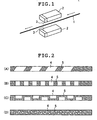
- the surface formed of the resin containing a laser color developing agent was irradiated with YAG laser light by a laser light irradiation method shown in FIG. 1, whereby a mark was formed.
- the movement speed of the guide wire was 300 mm/min., and the energy output of an irradiation origin was 1800 W.
- the surface was coated with a maleic anhydride ethyl ester copolymer by dipping, followed by being dried.
- a medical long object (guide wire) of the present invention was obtained.
- a medical long object (guide wire) of the present invention was obtained by the same method as that of Example 1, except that irradiation with laser light was conducted after coating of a maleic anhydride ethyl ester copolymer in place of conducting coating of a maleic anhydride ethyl ester copolymer after irradiation with laser light.
- core wires made of a Ni-Ti alloy
- the resultant resin containing a laser color developing agent by extrusion molding so as to have outer diameters respectively shown in Table 1.
- Each core wire thus obtained was cut in predetermined length and the core wire was coated (hydrophilic polymer coat portion) with a hydrophilic polymer (a maleic anhydride ester copolymer) to a length shown in Table 1 from a tip end portion by dipping. Thereafter, the surface formed of the resin containing a laser color developing agent was irradiated with YAG laser light by the laser light irradiation method shown in FIG. 1, whereby a mark was formed (visual marker portion).
- the movement speed of the guide wire was 300 mm/min., and the energy output of an irradiation origin was 1800 W.
- FIGs. 3E and 3F show plan views of medical long objects (guide wires) produced in Example 3.
- reference numeral 4 denotes a color developing portion
- 5 denotes a non-color developing portion
- 6 denotes a visual marker portion
- 7 denotes a hydrophilic polymer coat portion
- 8 denotes a hand part silicon coat portion.
- Table 1 shows the size and the like of each portion of the guide wires produced in Example 3.
- Table 1 Example Guide wire outer diameter mm (inch) Guide wire length cm Hydrophilic polymer coat portion length cm Laser treatment length cm Laser treatment shape 3-1 0.635(0.025) 260 5 10 E 0.635(0.025) 260 50 20 E 0.635(0.025) 260 100 30 E 3-2 0.635(0.025) 450 5 10 E 0.635(0.025) 450 50 20 E 0.635(0.025) 450 100 30 E 3-3 0.889(0.035) 260 5 10 F 0.889(0.035) 260 50 20 F 0.889(0.035) 260 100 30 F 3-4 0.889(0.035) 450 5 10 F 0.889(0.035) 450 50 20 F 0.889(0.035) 450 100 30 F
- the guide wires of the present invention obtained in Examples 1 to 3 had marks with a desired shape at a desired position, whereby the movement of the guide wires in an axial direction was able to be recognized during such as insertion. Furthermore, marks did not peel off during use. Furthermore, the guide wires of the present invention had a smooth surface (cylindrical surface), and a raise and a recess were not present in the mark portions.
- the medical long object of the present invention is provided with marks at least in a part of the surface thereof, so that the movement of the medical long object in an axial direction is recognized. Furthermore, information on a scale and the like can be displayed, so that the medical long object of the present invention is useful. Furthermore, the medical long object of the present invention has no problems that have not been conventionally solved.
- the medical long object of the present invention can be preferably produced.
Claims (7)
- Fil de guidage (1) ou cathéter ayant une marque sur sa surface, comprenant :- une partie faite d'un matériau polymère contenant un agent de développement de couleur laser au moins dans une partie d'une surface,- un revêtement polymère hydrophile transparent ou semi-transparent (7) couvrant au moins la partie de ladite surface,- une partie de développement de couleur adaptée au développement de couleur de l'agent de développement de couleur laser dû à l'irradiation par une lumière laser (3) dans la partie de ladite surface après le dépôt du polymère hydrophile (7).
- Fil de guidage (1) ou cathéter selon la revendication 1, comportant un embout et une extrémité de base, dans lequel ladite surface du matériau polymère est au moins en partie dans l'embout, et ladite partie de développement de couleur se trouve sur la surface du matériau polymère.
- Fil de guidage (1) ou cathéter selon la revendication 1 ou 2, dans lequel l'agent de développement de couleur laser contient un mica et/ou un composé de mica.
- Procédé de fabrication d'un fil de guidage (1) ou d'un cathéter ayant une marque sur sa surface, comprenant :la formation d'au moins une partie d'une surface du fil de guidage (1) ou d'un cathéter avec un matériau polymère contenant un agent de développement de couleur laser;le dépôt d'un revêtement polymère hydrophile (7) transparent ou semi-transparent sur la partie de la surface ; et enfinl'irradiation d'une partie seulement de la surface du fil de guidage (1) ou du cathéter dans laquelle une couleur doit être développée avec une lumière laser (3) afin de permettre à l'agent de développement de couleur laser de développer une couleur, formant de ce fait n'importe quel dessin à la surface du fil de guidage (1) ou du cathéter, l'irradiation avec la lumière laser (3) se produisant après que la partie de la surface ait été revêtue du polymère hydrophile (7).
- Procédé selon la revendication 4, dans lequel ladite partie de la surface du fil de guidage (1) ou du cathéter est pourvue d'un matériau polymère contenant un agent de développement de couleur laser dans un embout du fil de guidage (1) ou du cathéter.
- Procédé selon la revendication 4 ou 5, dans lequel l'agent de développement de couleur laser contient un mica et/ou un composé de mica.
- Procédé selon l'une quelconque des revendications 4 à 6, dans lequel l'agent de développement de couleur laser est contenu dans le composant matériau polymère en un pourcentage massique de 0,01 à 10 %, par rapport à la quantité totale de ce composant.
Applications Claiming Priority (2)
| Application Number | Priority Date | Filing Date | Title |
|---|---|---|---|
| JP2000330522A JP2002136600A (ja) | 2000-10-30 | 2000-10-30 | 医療用長尺体およびその製造方法 |
| JP2000330522 | 2000-10-30 |
Publications (2)
| Publication Number | Publication Date |
|---|---|
| EP1203595A1 EP1203595A1 (fr) | 2002-05-08 |
| EP1203595B1 true EP1203595B1 (fr) | 2007-01-24 |
Family
ID=18807025
Family Applications (1)
| Application Number | Title | Priority Date | Filing Date |
|---|---|---|---|
| EP01125342A Expired - Lifetime EP1203595B1 (fr) | 2000-10-30 | 2001-10-29 | Méthode de marquage d'objets médicaux allongés et cathéter obtenu ainsi |
Country Status (5)
| Country | Link |
|---|---|
| US (2) | US6811958B2 (fr) |
| EP (1) | EP1203595B1 (fr) |
| JP (1) | JP2002136600A (fr) |
| AT (1) | ATE352341T1 (fr) |
| DE (1) | DE60126220T2 (fr) |
Families Citing this family (46)
| Publication number | Priority date | Publication date | Assignee | Title |
|---|---|---|---|---|
| JPS62129097A (ja) * | 1986-08-29 | 1987-06-11 | 株式会社日立製作所 | 洗たく機 |
| US7416554B2 (en) | 2002-12-11 | 2008-08-26 | Usgi Medical Inc | Apparatus and methods for forming and securing gastrointestinal tissue folds |
| JP4282979B2 (ja) | 2002-03-25 | 2009-06-24 | テルモ株式会社 | ガイドワイヤ |
| US7942898B2 (en) * | 2002-12-11 | 2011-05-17 | Usgi Medical, Inc. | Delivery systems and methods for gastric reduction |
| US7942884B2 (en) | 2002-12-11 | 2011-05-17 | Usgi Medical, Inc. | Methods for reduction of a gastric lumen |
| JP2004195030A (ja) | 2002-12-19 | 2004-07-15 | Pentax Corp | 内視鏡関連品および内視鏡 |
| JP2004195031A (ja) * | 2002-12-19 | 2004-07-15 | Pentax Corp | 内視鏡用測長具 |
| JP2004229947A (ja) * | 2003-01-31 | 2004-08-19 | Terumo Corp | ガイドワイヤ |
| US20040180765A1 (en) * | 2003-03-11 | 2004-09-16 | Float Jeffrey J. | Vertical swim-training apparatus |
| WO2004096310A2 (fr) * | 2003-04-25 | 2004-11-11 | Cook, Inc. | Fil-guide dote d'un marquage et d'un revetement a faible coefficient de frottement pour introduction d'un catheter sur fil-guide |
| US7756737B2 (en) * | 2003-12-17 | 2010-07-13 | Hewlett-Packard Development Company, L.P. | User-based method and system for evaluating enterprise software services costs |
| US20060015039A1 (en) * | 2004-07-19 | 2006-01-19 | Cassidy Kenneth T | Guidewire bearing markings simplifying catheter selection |
| CA2590001C (fr) * | 2004-12-15 | 2011-10-18 | Wilson-Cook Medical Inc. | Dispositif medical tres peu invasif avec modele helicoidal pour indiquer une distance de mouvement |
| EP1839554B1 (fr) * | 2005-01-21 | 2013-12-25 | Olympus Corporation | Endoscope, appareil medical pour l'endoscope et procede d'application de marquage de cellui-ci |
| JP2007306944A (ja) * | 2005-01-21 | 2007-11-29 | Olympus Corp | 内視鏡及び内視鏡用医療器具並びにその表示方法 |
| JP5002245B2 (ja) * | 2005-12-27 | 2012-08-15 | テルモ株式会社 | ガイドワイヤ |
| EP2103323B1 (fr) | 2007-03-14 | 2012-04-25 | Terumo Kabushiki Kaisha | Guide-fil |
| US9028427B2 (en) | 2007-03-14 | 2015-05-12 | Terumo Kabushiki Kaisha | Guide wire |
| ES2401525T3 (es) * | 2007-03-30 | 2013-04-22 | Piolax Medical Devices, Inc. | Cable guía médico |
| US10064635B2 (en) * | 2007-04-17 | 2018-09-04 | Covidien Lp | Articulating retrieval devices |
| JP2009113833A (ja) * | 2007-11-06 | 2009-05-28 | Csi Japan:Kk | キャップ、閉止装置および飲料入り閉止装置 |
| US9579496B2 (en) | 2007-11-07 | 2017-02-28 | C. R. Bard, Inc. | Radiopaque and septum-based indicators for a multi-lumen implantable port |
| US8231926B2 (en) | 2007-12-21 | 2012-07-31 | Innovatech, Llc | Marked precoated medical device and method of manufacturing same |
| US8231927B2 (en) * | 2007-12-21 | 2012-07-31 | Innovatech, Llc | Marked precoated medical device and method of manufacturing same |
| US7811623B2 (en) | 2007-12-21 | 2010-10-12 | Innovatech, Llc | Marked precoated medical device and method of manufacturing same |
| US7714217B2 (en) * | 2007-12-21 | 2010-05-11 | Innovatech, Llc | Marked precoated strings and method of manufacturing same |
| US8048471B2 (en) | 2007-12-21 | 2011-11-01 | Innovatech, Llc | Marked precoated medical device and method of manufacturing same |
| CN102112175B (zh) * | 2008-08-11 | 2013-08-07 | 泰尔茂株式会社 | 医疗器械 |
| US11890443B2 (en) | 2008-11-13 | 2024-02-06 | C. R. Bard, Inc. | Implantable medical devices including septum-based indicators |
| JP5481116B2 (ja) * | 2009-07-16 | 2014-04-23 | Hoya株式会社 | 内視鏡用アングルノブ |
| BR112012007392A2 (pt) * | 2009-10-02 | 2016-12-06 | Medtronic Xomed Inc | aparelho e método para monitorar sinais eletromiográficos (emg) de músculos da laringe de paciente |
| US20110106057A1 (en) * | 2009-11-02 | 2011-05-05 | Hamboly M Samy Ahmed | Catheter guidewire advancement device |
| US9079004B2 (en) | 2009-11-17 | 2015-07-14 | C. R. Bard, Inc. | Overmolded access port including anchoring and identification features |
| CN103249572B (zh) * | 2010-10-26 | 2016-06-22 | 沙特基础全球技术有限公司 | 具有全部颜色性能的激光直接结构化材料 |
| US8900652B1 (en) | 2011-03-14 | 2014-12-02 | Innovatech, Llc | Marked fluoropolymer surfaces and method of manufacturing same |
| CN106274107A (zh) * | 2011-04-18 | 2017-01-04 | 英格朗公司 | 聚合构件和用于标记聚合构件的方法 |
| US9358091B2 (en) | 2011-04-18 | 2016-06-07 | Inguran, Llc | Two-dimensional bar codes in assisted reproductive technologies |
| WO2013129027A1 (fr) * | 2012-02-27 | 2013-09-06 | テルモ株式会社 | Procédé de formation de sections de marquage pour tube médical, tube médical, et dispositif médical |
| WO2015013770A1 (fr) * | 2013-08-02 | 2015-02-05 | Withers Teresa Kathryn | Dispositif pour cathéter |
| JP6178188B2 (ja) * | 2013-09-26 | 2017-08-09 | テルモ株式会社 | 医療デバイスおよび医療デバイスの製造方法 |
| JP6426068B2 (ja) * | 2015-08-10 | 2018-11-21 | 朝日インテック株式会社 | カテーテル及びバルーンカテーテル |
| WO2017057389A1 (fr) * | 2015-09-29 | 2017-04-06 | テルモ株式会社 | Élément allongé médical |
| CN106861020B (zh) * | 2017-03-15 | 2024-02-20 | 北京聚精瑞生医疗科技有限公司 | 一种荧光自显影潜行穿刺导丝 |
| US11364077B2 (en) * | 2017-03-24 | 2022-06-21 | The Spectranetics Corporation | Laser energy delivery devices including distal tip orientation indicators |
| DE102018119605A1 (de) * | 2018-08-13 | 2020-02-13 | Elringklinger Ag | Positioniervorrichtung und Verfahren zum Herstellen einer Positioniervorrichtung |
| EP3671861A1 (fr) * | 2018-12-17 | 2020-06-24 | Nexperia B.V. | Dispositif semi-conducteur et contact électrique |
Family Cites Families (15)
| Publication number | Priority date | Publication date | Assignee | Title |
|---|---|---|---|---|
| DE3506750C1 (de) | 1985-02-26 | 1986-02-20 | B. Braun Melsungen Ag, 3508 Melsungen | Verfahren zum Erzeugen von Farbmarkierungen auf einem Katheter-Fuehrungsdraht |
| US5084022A (en) * | 1989-10-04 | 1992-01-28 | Lake Region Manufacturing Company, Inc. | Graduated guidewire |
| JPH04108556U (ja) | 1991-02-28 | 1992-09-18 | 株式会社ニツシヨー | ガイドワイヤ |
| US5241970A (en) | 1991-05-17 | 1993-09-07 | Wilson-Cook Medical, Inc. | Papillotome/sphincterotome procedures and a wire guide specially |
| WO1993010939A1 (fr) * | 1991-12-04 | 1993-06-10 | Colorado Laser Marking, Inc. | Appareil et procede de marquage de tubes a paroi mince |
| WO1994001160A1 (fr) * | 1992-07-14 | 1994-01-20 | Arrow International Investment Corporation | Catheter epidural a double durometre en une seule piece |
| US5919170A (en) * | 1993-02-01 | 1999-07-06 | Mentor Corporation | Urinary catheter |
| JPH0663054U (ja) | 1993-02-15 | 1994-09-06 | ユニチカ株式会社 | カテーテルのガイドワイヤー |
| US5379779A (en) * | 1993-08-16 | 1995-01-10 | Boston Scientific Corporation | Zebra exchange guidewire |
| US6673025B1 (en) * | 1993-12-01 | 2004-01-06 | Advanced Cardiovascular Systems, Inc. | Polymer coated guidewire |
| CA2142492A1 (fr) * | 1994-02-24 | 1995-08-25 | Masaki Shinmoto | Composition de marquage, moulures et methode de marquage |
| US5928842A (en) * | 1994-02-24 | 1999-07-27 | Nippon Kayaku Kabushiki Kaisha | Marking method |
| US5811369A (en) * | 1995-12-01 | 1998-09-22 | Nippon Paper Industries Co., Ltd. | Thermal recording medium |
| US6520951B1 (en) * | 1996-09-13 | 2003-02-18 | Scimed Life Systems, Inc. | Rapid exchange catheter with detachable hood |
| US5977514A (en) * | 1997-06-13 | 1999-11-02 | M.A. Hannacolor | Controlled color laser marking of plastics |
-
2000
- 2000-10-30 JP JP2000330522A patent/JP2002136600A/ja active Pending
-
2001
- 2001-10-29 AT AT01125342T patent/ATE352341T1/de not_active IP Right Cessation
- 2001-10-29 EP EP01125342A patent/EP1203595B1/fr not_active Expired - Lifetime
- 2001-10-29 DE DE60126220T patent/DE60126220T2/de not_active Expired - Lifetime
- 2001-10-30 US US09/984,611 patent/US6811958B2/en not_active Expired - Lifetime
-
2004
- 2004-09-28 US US10/950,626 patent/US20050080358A1/en not_active Abandoned
Also Published As
| Publication number | Publication date |
|---|---|
| US20020087098A1 (en) | 2002-07-04 |
| US6811958B2 (en) | 2004-11-02 |
| US20050080358A1 (en) | 2005-04-14 |
| JP2002136600A (ja) | 2002-05-14 |
| DE60126220T2 (de) | 2007-11-08 |
| EP1203595A1 (fr) | 2002-05-08 |
| DE60126220D1 (de) | 2007-03-15 |
| ATE352341T1 (de) | 2007-02-15 |
Similar Documents
| Publication | Publication Date | Title |
|---|---|---|
| EP1203595B1 (fr) | Méthode de marquage d'objets médicaux allongés et cathéter obtenu ainsi | |
| EP1348461B1 (fr) | Fil de guidage | |
| EP0714315B1 (fr) | Fil de guidage d'echange presentant des bandes alternees | |
| US6179811B1 (en) | Imbedded marker and flexible guide wire shaft | |
| US5908413A (en) | Radiopaque catheter and method of manufacture thereof | |
| US9028427B2 (en) | Guide wire | |
| US20050255317A1 (en) | Polymeric marker with high radiopacity for use in medical devices | |
| JP4696071B2 (ja) | ポリマーマトリックスに埋め込まれたコイルを有するガイドワイヤ | |
| JP2001190681A (ja) | カテーテル | |
| JP2001046508A (ja) | 医療用ガイドワイヤ | |
| JP2003275323A (ja) | 医療用長尺体 | |
| US20040180765A1 (en) | Vertical swim-training apparatus | |
| JP3761216B2 (ja) | 医療用ガイドワイヤ及びその製造法 | |
| EP2153861B1 (fr) | Fil de guidage médical | |
| JP5033201B2 (ja) | 医療用ガイドワイヤ | |
| JP3761214B2 (ja) | 医療用ガイドワイヤ | |
| JP3949986B2 (ja) | 医療用長尺体 | |
| JP2004008653A (ja) | ガイドワイヤ | |
| EP3603729B1 (fr) | Instrument médical | |
| JP2002017864A (ja) | 医療用ガイドワイヤ | |
| JP7461753B2 (ja) | ガイドワイヤ | |
| JP3915165B2 (ja) | マーカー付きカテーテル | |
| US20230200845A1 (en) | Guidewire having guidewire markers | |
| JP2022112907A (ja) | 医療用長尺体と視認方法およびトレーニング方法 |
Legal Events
| Date | Code | Title | Description |
|---|---|---|---|
| PUAI | Public reference made under article 153(3) epc to a published international application that has entered the european phase |
Free format text: ORIGINAL CODE: 0009012 |
|
| AK | Designated contracting states |
Kind code of ref document: A1 Designated state(s): AT BE CH CY DE DK ES FI FR GB GR IE IT LI LU MC NL PT SE TR |
|
| AX | Request for extension of the european patent |
Free format text: AL;LT;LV;MK;RO;SI |
|
| 17P | Request for examination filed |
Effective date: 20021029 |
|
| AKX | Designation fees paid |
Designated state(s): AT BE CH CY DE DK ES FI FR GB GR IE IT LI LU MC NL PT SE TR |
|
| 17Q | First examination report despatched |
Effective date: 20041228 |
|
| GRAP | Despatch of communication of intention to grant a patent |
Free format text: ORIGINAL CODE: EPIDOSNIGR1 |
|
| GRAS | Grant fee paid |
Free format text: ORIGINAL CODE: EPIDOSNIGR3 |
|
| GRAA | (expected) grant |
Free format text: ORIGINAL CODE: 0009210 |
|
| AK | Designated contracting states |
Kind code of ref document: B1 Designated state(s): AT BE CH CY DE DK ES FI FR GB GR IE IT LI LU MC NL PT SE TR |
|
| PG25 | Lapsed in a contracting state [announced via postgrant information from national office to epo] |
Ref country code: NL Free format text: LAPSE BECAUSE OF FAILURE TO SUBMIT A TRANSLATION OF THE DESCRIPTION OR TO PAY THE FEE WITHIN THE PRESCRIBED TIME-LIMIT Effective date: 20070124 Ref country code: LI Free format text: LAPSE BECAUSE OF FAILURE TO SUBMIT A TRANSLATION OF THE DESCRIPTION OR TO PAY THE FEE WITHIN THE PRESCRIBED TIME-LIMIT Effective date: 20070124 Ref country code: DK Free format text: LAPSE BECAUSE OF FAILURE TO SUBMIT A TRANSLATION OF THE DESCRIPTION OR TO PAY THE FEE WITHIN THE PRESCRIBED TIME-LIMIT Effective date: 20070124 Ref country code: CH Free format text: LAPSE BECAUSE OF FAILURE TO SUBMIT A TRANSLATION OF THE DESCRIPTION OR TO PAY THE FEE WITHIN THE PRESCRIBED TIME-LIMIT Effective date: 20070124 Ref country code: AT Free format text: LAPSE BECAUSE OF FAILURE TO SUBMIT A TRANSLATION OF THE DESCRIPTION OR TO PAY THE FEE WITHIN THE PRESCRIBED TIME-LIMIT Effective date: 20070124 Ref country code: FI Free format text: LAPSE BECAUSE OF FAILURE TO SUBMIT A TRANSLATION OF THE DESCRIPTION OR TO PAY THE FEE WITHIN THE PRESCRIBED TIME-LIMIT Effective date: 20070124 |
|
| REG | Reference to a national code |
Ref country code: GB Ref legal event code: FG4D |
|
| REG | Reference to a national code |
Ref country code: CH Ref legal event code: EP |
|
| REG | Reference to a national code |
Ref country code: IE Ref legal event code: FG4D |
|
| REF | Corresponds to: |
Ref document number: 60126220 Country of ref document: DE Date of ref document: 20070315 Kind code of ref document: P |
|
| PG25 | Lapsed in a contracting state [announced via postgrant information from national office to epo] |
Ref country code: SE Free format text: LAPSE BECAUSE OF FAILURE TO SUBMIT A TRANSLATION OF THE DESCRIPTION OR TO PAY THE FEE WITHIN THE PRESCRIBED TIME-LIMIT Effective date: 20070424 |
|
| PG25 | Lapsed in a contracting state [announced via postgrant information from national office to epo] |
Ref country code: ES Free format text: LAPSE BECAUSE OF FAILURE TO SUBMIT A TRANSLATION OF THE DESCRIPTION OR TO PAY THE FEE WITHIN THE PRESCRIBED TIME-LIMIT Effective date: 20070505 |
|
| ET | Fr: translation filed | ||
| PG25 | Lapsed in a contracting state [announced via postgrant information from national office to epo] |
Ref country code: PT Free format text: LAPSE BECAUSE OF FAILURE TO SUBMIT A TRANSLATION OF THE DESCRIPTION OR TO PAY THE FEE WITHIN THE PRESCRIBED TIME-LIMIT Effective date: 20070625 |
|
| REG | Reference to a national code |
Ref country code: CH Ref legal event code: PL |
|
| NLV1 | Nl: lapsed or annulled due to failure to fulfill the requirements of art. 29p and 29m of the patents act | ||
| PLBE | No opposition filed within time limit |
Free format text: ORIGINAL CODE: 0009261 |
|
| STAA | Information on the status of an ep patent application or granted ep patent |
Free format text: STATUS: NO OPPOSITION FILED WITHIN TIME LIMIT |
|
| 26N | No opposition filed |
Effective date: 20071025 |
|
| PG25 | Lapsed in a contracting state [announced via postgrant information from national office to epo] |
Ref country code: BE Free format text: LAPSE BECAUSE OF FAILURE TO SUBMIT A TRANSLATION OF THE DESCRIPTION OR TO PAY THE FEE WITHIN THE PRESCRIBED TIME-LIMIT Effective date: 20070124 |
|
| PG25 | Lapsed in a contracting state [announced via postgrant information from national office to epo] |
Ref country code: GR Free format text: LAPSE BECAUSE OF FAILURE TO SUBMIT A TRANSLATION OF THE DESCRIPTION OR TO PAY THE FEE WITHIN THE PRESCRIBED TIME-LIMIT Effective date: 20070425 Ref country code: IT Free format text: LAPSE BECAUSE OF FAILURE TO SUBMIT A TRANSLATION OF THE DESCRIPTION OR TO PAY THE FEE WITHIN THE PRESCRIBED TIME-LIMIT Effective date: 20070124 |
|
| PG25 | Lapsed in a contracting state [announced via postgrant information from national office to epo] |
Ref country code: MC Free format text: LAPSE BECAUSE OF NON-PAYMENT OF DUE FEES Effective date: 20071031 |
|
| PG25 | Lapsed in a contracting state [announced via postgrant information from national office to epo] |
Ref country code: IE Free format text: LAPSE BECAUSE OF NON-PAYMENT OF DUE FEES Effective date: 20071030 |
|
| PG25 | Lapsed in a contracting state [announced via postgrant information from national office to epo] |
Ref country code: CY Free format text: LAPSE BECAUSE OF FAILURE TO SUBMIT A TRANSLATION OF THE DESCRIPTION OR TO PAY THE FEE WITHIN THE PRESCRIBED TIME-LIMIT Effective date: 20070124 |
|
| PG25 | Lapsed in a contracting state [announced via postgrant information from national office to epo] |
Ref country code: LU Free format text: LAPSE BECAUSE OF NON-PAYMENT OF DUE FEES Effective date: 20071029 |
|
| PG25 | Lapsed in a contracting state [announced via postgrant information from national office to epo] |
Ref country code: TR Free format text: LAPSE BECAUSE OF FAILURE TO SUBMIT A TRANSLATION OF THE DESCRIPTION OR TO PAY THE FEE WITHIN THE PRESCRIBED TIME-LIMIT Effective date: 20070124 |
|
| PGFP | Annual fee paid to national office [announced via postgrant information from national office to epo] |
Ref country code: FR Payment date: 20121018 Year of fee payment: 12 |
|
| PGFP | Annual fee paid to national office [announced via postgrant information from national office to epo] |
Ref country code: GB Payment date: 20121024 Year of fee payment: 12 |
|
| GBPC | Gb: european patent ceased through non-payment of renewal fee |
Effective date: 20131029 |
|
| PG25 | Lapsed in a contracting state [announced via postgrant information from national office to epo] |
Ref country code: GB Free format text: LAPSE BECAUSE OF NON-PAYMENT OF DUE FEES Effective date: 20131029 |
|
| REG | Reference to a national code |
Ref country code: FR Ref legal event code: ST Effective date: 20140630 |
|
| PG25 | Lapsed in a contracting state [announced via postgrant information from national office to epo] |
Ref country code: FR Free format text: LAPSE BECAUSE OF NON-PAYMENT OF DUE FEES Effective date: 20131031 |
|
| PGFP | Annual fee paid to national office [announced via postgrant information from national office to epo] |
Ref country code: DE Payment date: 20181016 Year of fee payment: 18 |
|
| REG | Reference to a national code |
Ref country code: DE Ref legal event code: R119 Ref document number: 60126220 Country of ref document: DE |
|
| PG25 | Lapsed in a contracting state [announced via postgrant information from national office to epo] |
Ref country code: DE Free format text: LAPSE BECAUSE OF NON-PAYMENT OF DUE FEES Effective date: 20200501 |