EP1167832B1 - Eingangskupplungs- Schmiersteuerungsanlage für ein automatisches Getriebe - Google Patents
Eingangskupplungs- Schmiersteuerungsanlage für ein automatisches Getriebe Download PDFInfo
- Publication number
- EP1167832B1 EP1167832B1 EP01112576A EP01112576A EP1167832B1 EP 1167832 B1 EP1167832 B1 EP 1167832B1 EP 01112576 A EP01112576 A EP 01112576A EP 01112576 A EP01112576 A EP 01112576A EP 1167832 B1 EP1167832 B1 EP 1167832B1
- Authority
- EP
- European Patent Office
- Prior art keywords
- lubrication
- input clutch
- clutch
- lubricating oil
- circuit
- Prior art date
- Legal status (The legal status is an assumption and is not a legal conclusion. Google has not performed a legal analysis and makes no representation as to the accuracy of the status listed.)
- Expired - Lifetime
Links
Images


Classifications
-
- F—MECHANICAL ENGINEERING; LIGHTING; HEATING; WEAPONS; BLASTING
- F16—ENGINEERING ELEMENTS AND UNITS; GENERAL MEASURES FOR PRODUCING AND MAINTAINING EFFECTIVE FUNCTIONING OF MACHINES OR INSTALLATIONS; THERMAL INSULATION IN GENERAL
- F16H—GEARING
- F16H57/00—General details of gearing
- F16H57/04—Features relating to lubrication or cooling or heating
- F16H57/048—Type of gearings to be lubricated, cooled or heated
- F16H57/0482—Gearings with gears having orbital motion
-
- F—MECHANICAL ENGINEERING; LIGHTING; HEATING; WEAPONS; BLASTING
- F16—ENGINEERING ELEMENTS AND UNITS; GENERAL MEASURES FOR PRODUCING AND MAINTAINING EFFECTIVE FUNCTIONING OF MACHINES OR INSTALLATIONS; THERMAL INSULATION IN GENERAL
- F16D—COUPLINGS FOR TRANSMITTING ROTATION; CLUTCHES; BRAKES
- F16D27/00—Magnetically- or electrically- actuated clutches; Control or electric circuits therefor
- F16D27/10—Magnetically- or electrically- actuated clutches; Control or electric circuits therefor with an electromagnet not rotating with a clutching member, i.e. without collecting rings
- F16D27/108—Magnetically- or electrically- actuated clutches; Control or electric circuits therefor with an electromagnet not rotating with a clutching member, i.e. without collecting rings with axially movable clutching members
- F16D27/112—Magnetically- or electrically- actuated clutches; Control or electric circuits therefor with an electromagnet not rotating with a clutching member, i.e. without collecting rings with axially movable clutching members with flat friction surfaces, e.g. discs
- F16D27/115—Magnetically- or electrically- actuated clutches; Control or electric circuits therefor with an electromagnet not rotating with a clutching member, i.e. without collecting rings with axially movable clutching members with flat friction surfaces, e.g. discs with more than two discs, e.g. multiple lamellae
-
- F—MECHANICAL ENGINEERING; LIGHTING; HEATING; WEAPONS; BLASTING
- F16—ENGINEERING ELEMENTS AND UNITS; GENERAL MEASURES FOR PRODUCING AND MAINTAINING EFFECTIVE FUNCTIONING OF MACHINES OR INSTALLATIONS; THERMAL INSULATION IN GENERAL
- F16H—GEARING
- F16H61/00—Control functions within control units of change-speed- or reversing-gearings for conveying rotary motion ; Control of exclusively fluid gearing, friction gearing, gearings with endless flexible members or other particular types of gearing
- F16H61/0021—Generation or control of line pressure
-
- F—MECHANICAL ENGINEERING; LIGHTING; HEATING; WEAPONS; BLASTING
- F16—ENGINEERING ELEMENTS AND UNITS; GENERAL MEASURES FOR PRODUCING AND MAINTAINING EFFECTIVE FUNCTIONING OF MACHINES OR INSTALLATIONS; THERMAL INSULATION IN GENERAL
- F16H—GEARING
- F16H61/00—Control functions within control units of change-speed- or reversing-gearings for conveying rotary motion ; Control of exclusively fluid gearing, friction gearing, gearings with endless flexible members or other particular types of gearing
- F16H61/38—Control of exclusively fluid gearing
- F16H61/40—Control of exclusively fluid gearing hydrostatic
- F16H61/4165—Control of cooling or lubricating
-
- F—MECHANICAL ENGINEERING; LIGHTING; HEATING; WEAPONS; BLASTING
- F16—ENGINEERING ELEMENTS AND UNITS; GENERAL MEASURES FOR PRODUCING AND MAINTAINING EFFECTIVE FUNCTIONING OF MACHINES OR INSTALLATIONS; THERMAL INSULATION IN GENERAL
- F16D—COUPLINGS FOR TRANSMITTING ROTATION; CLUTCHES; BRAKES
- F16D2300/00—Special features for couplings or clutches
- F16D2300/06—Lubrication details not provided for in group F16D13/74
-
- F—MECHANICAL ENGINEERING; LIGHTING; HEATING; WEAPONS; BLASTING
- F16—ENGINEERING ELEMENTS AND UNITS; GENERAL MEASURES FOR PRODUCING AND MAINTAINING EFFECTIVE FUNCTIONING OF MACHINES OR INSTALLATIONS; THERMAL INSULATION IN GENERAL
- F16D—COUPLINGS FOR TRANSMITTING ROTATION; CLUTCHES; BRAKES
- F16D27/00—Magnetically- or electrically- actuated clutches; Control or electric circuits therefor
- F16D27/004—Magnetically- or electrically- actuated clutches; Control or electric circuits therefor with permanent magnets combined with electromagnets
-
- F—MECHANICAL ENGINEERING; LIGHTING; HEATING; WEAPONS; BLASTING
- F16—ENGINEERING ELEMENTS AND UNITS; GENERAL MEASURES FOR PRODUCING AND MAINTAINING EFFECTIVE FUNCTIONING OF MACHINES OR INSTALLATIONS; THERMAL INSULATION IN GENERAL
- F16H—GEARING
- F16H57/00—General details of gearing
- F16H57/04—Features relating to lubrication or cooling or heating
- F16H57/0467—Elements of gearings to be lubricated, cooled or heated
- F16H57/0473—Friction devices, e.g. clutches or brakes
Definitions
- the present invention relates to an apparatus for controlling lubrication in an input clutch used in an automatic transmission, and specifically, to an apparatus for controlling lubrication in an electromagnetic input clutch.
- an automatic transmission of a continuously variable type (stepless transmission) or a non-continuously variable type (stepwise transmission) is so constructed as to receive rotation of an engine as a power source via a torque converter.
- the torque converter transmits the power between input and output elements by hydrodynamic force.
- the torque converter can perform smooth transmission of the power, but there will occur slippage between the input and output elements, causing decrease in fuel economy.
- the electromagnetic clutch is used for the input clutch, it is required to apply the input clutch at a slipping state in order to prevent undesired shock from being caused upon the starting or speed-change operation of the automatic transmission. Accordingly, the electromagnetic input clutch must be lubricated.
- the lubrication circuit of the electromagnetic input clutch includes an oil pump for pumping a lubricating oil from an oil source.
- the oil pump is disposed at the connection between a transmission casing and an input clutch housing.
- a control valve body is mounted to a lower portion of the transmission casing and adapted to control speed-change of the automatic transmission using the oil fed from the oil pump as a working medium.
- An excessive oil from the control valve body is utilized for lubricating the electromagnetic input clutch within the input clutch housing.
- the lubricating oil to be used for lubrication of the electromagnetic input clutch must be supplied from the central portion of the input clutch because the input clutch per se is a rotor. Therefore, the lubrication circuit cannot be formed at the outer periphery of the input clutch. For the reasons described above, the formation of the lubrication circuit tends to increase diameter of a transmission input shaft and radial dimension of the entire automatic transmission.
- US 5,347,886 discloses a lubrication system for multi-plate clutch assemblies which is controlled to provide increased lube flow.
- lube flow is increased periodically for a short time interval.
- the lube flow is maintained at a level requiring minimum fluid flow for the system.
- EP 0 875 690 A2 describes a clutch assembly having reaction force circuit which includes an internal redaction force circuit comprising a multiple disc friction clutch disposed adjacent an operator assembly which selectively applies force to the friction clutch to selectively transfer torque therethrough.
- An object of the present invention is to provide an apparatus for controlling lubrication in an input clutch of an automatic transmission, which is provided with two parallel lubrication circuits for the input clutch without increasing radial dimensions of a transmission input shaft and the automatic transmission and is capable of readily controlling an amount of a lubricating oil to be used for lubrication in the input clutch.
- a further object of the present invention is to provide an apparatus for lubricating an electromagnetic input clutch of an automatic transmission, which is capable of being constructed without substantially changing the design of the automatic transmission utilizing a torque converter.
- an input clutch lubrication control apparatus for au automatic transmission comprising:
- an input clutch lubrication control apparatus for au automatic transmission comprising:
- an automatic transmission comprising:
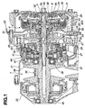
- the automatic transmission is in the form of a V-belt continuously variable transmission (CVT) including speed change section 7 as explained later.
- CVT continuously variable transmission
- the V-belt CVT includes transmission casing 21, end cover 22 closing a rear end opening of transmission casing 21, and input clutch housing 23 attached to a front end opening of transmission casing 21.
- Oil pump 24 is disposed between transmission casing 21 and input clutch housing 23.
- Oil pump 24 is in the form of a gear pump which includes pump housing 25, pump cover 26 cooperating with pump housing 25 to define a space therebetween, and an internal gear pump element disposed within the space.
- Stationary sleeve 27 is received into a central opening of pump cover 26 in a fitting relation to an inner circumferential surface of pump cover 26 which defines the central opening.
- Input shaft 5 is rotatably supported by sleeve 27.
- Input clutch 4 is mounted onto a front portion of input shaft 5 which projects into an inside of input clutch housing 23.
- Input clutch 4 is electromagnetically operated and includes electromagnetic clutch 28, input clutch pack 29 disposed on an outer periphery of electromagnetic clutch 28, and loading cam 30 disposed on an inner periphery of electromagnetic clutch 28.
- Electromagnetic clutch 28 is adapted to transmit rotation of clutch drum 33 to loading cam 30 when electromagnetic clutch 28 is in an applied or engaged state.
- Clutch drum 33 is drivingly connected to an engine crankshaft (not shown) via torsional damper 31 and drive plate 32. Clutch drum 33 acts as a drive shaft of oil pump 24.
- loading cam 30 When loading cam 30 receives engine rotation upon application of electromagnetic clutch 28, loading cam 30 exhibits cam function by the rolling contact between balls and a sloped cam surface. A thrust force is caused and exerted on input clutch hub 34 splined to input shaft 5, to the right side in Fig. 1. Input clutch hub 34 is moved in the direction to urge input clutch pack 29 by an outer circumferential portion thereof. Input clutch pack 29 is brought into an engaged state in which input clutch hub 34 is coupled with clutch drum 33. In this condition, input clutch 4 is in an applied state in which input clutch 4 transmits the engine rotation to input shaft 5 through clutch drum 33, input clutch pack 29 engaged, and input clutch hub 34.
- One-way clutch 8 is fitted to input shaft 5 between oil pump 24 and loading cam 30.
- Annular member 35 is rotatively engaged with an outer circumferential surface of one-way clutch 8 and secured to a front end portion of stationary sleeve 27.
- Annular member 35 and sleeve 27 act as a reaction force receiving member for one-way clutch 8 which prohibits a rotation of input shaft 5 reverse to the engine rotation so that one-way clutch 8 can effect a hill-hold function for preventing the vehicle from rolling on a slope.
- Speed change section 7 includes primary pulley 36, secondary pulley 37 and V-belt 38 connecting primary and secondary pulleys 36 and 37.
- Primary pulley 36 is fitted onto a rear end portion of input shaft 5 which projects into transmission casing 21.
- Primary pulley 36 has a front end supported on transmission casing 21 through bearing 39 and a rear end supported on end cover 22 through bearing 40.
- Each of primary and secondary pulleys 36 and 37 defines a V-groove engaged with V-belt 38 and is controllable to change a width of the V-groove which extends in the axial direction of input shaft 5.
- a radius of curvature of a circular arc formed by V-belt 38 spanned on pulleys 36 and 37 is continuously changed by changing the V-groove width.
- Speed change section 7 can thus conduct a continuously variable transmission operation. Rotation output with speed change is transmitted from secondary pulley 37 to drive wheels via differential gears (not shown).
- Forward-reverse switching mechanism 41 is disposed at the connection where input shaft 5 and primary pulley 36 are coupled with each other.
- Forward-reverse switching mechanism 41 includes simple planetary gear set 42, wet multiple-disc forward clutch 43 and reverse brake 44.
- Simple planetary gear set 42 includes a ring gear drivingly coupled with input shaft 5 via clutch drum 45 of forward clutch 43 so as to act as an input element, a sun gear drivingly coupled with primary pulley 36 so as to act as an output element, and a carrier connected with hub 46 of reverse brake 44 so as to act as a reaction force receiving member.
- Forward clutch 43 is operative to make simple planetary gear set 42 as one unit by drivingly connecting the ring gear and the sun gear when forward clutch 43 is engaged, to thereby transmit rotation of input shaft 5 to primary pulley 36 for forwardly driving the vehicle.
- Reverse brake 44 is operative to activate the carrier of simple planetary gear set 42 as the reaction force receiving member by fixing the carrier, to thereby transmit reduced reverse rotation of input shaft 5 to primary pulley 36 for reversely driving the vehicle.
- Fig. 1 Thus-constructed automatic transmission shown in Fig. 1 is operated as follows.
- non-travel range such as a neutral (N) range and a parking (P) range
- electromagnetic clutch 28 is deenergized to be in OFF position and thus input clutch 4 is in the released state.
- Forward clutch 43 and reverse brake 44 as start friction elements are in the released state with the working pressure drained. In this condition, the engine rotation is prevented from being transmitted to primary pulley 36 so that the vehicle is stopped.
- Input clutch 4 is enclosed in stationary input clutch casing 51 with the lubricating oil.
- Input clutch casing 51 is secured to the front end opening of transmission casing 21 together with input clutch housing 23.
- Input clutch casing 51 and input clutch housing 23 are mounted to transmission casing 21 in such a manner that the lubricating oil within input clutch casing 51 is prevented from leaking to input clutch housing 23.
- first lubrication circuit or passage 52 and second lubrication circuit or passage 53 fluidly communicating input clutch 4 with oil pump 24 for lubricating input clutch 4.
- First and second lubrication circuits 52 and 53 are arranged in parallel relation to each other.
- First lubrication circuit 52 includes annular space 5a disposed at the connection in which a front reduced-diameter portion of input shaft 5 is fitted into sleeve 27.
- Annular space 5a is formed between an inner circumferential surface of sleeve 27 and an outer circumferential surface of the reduced-diameter portion of input shaft 5.
- Annular space 5a is communicated with oil pump 24 and input clutch 4 via radial ports formed in sleeve 27.
- Second lubrication circuit 53 includes axial bore 5b of input shaft 5. Axial bore 5b is communicated with input clutch 4 via a radial port formed in input shaft 5 and communicated with oil pump 24 via radial ports formed in input shaft 5 and sleeve 27.
- an inlet fluid circuit for lockup control of conventional torque converter transmissions may be suitably used as first lubrication circuit 52 for input clutch 4.
- an outlet fluid circuit for lockup control of the conventional torque converter transmissions may be suitably used as second lubrication circuit 53 for input clutch 4.
- the lubricating oil is collected by a plurality of oil catching ribs 55A which are formed in input clutch casing 51 as shown in Fig. 2.
- oil catching ribs 55A are disposed inside a lower portion of input clutch casing 51.
- the lubricating oil that has lubricated input clutch 4 is collected in a space defined between oil catching ribs 55A.
- Oil catching ribs 55A uprightly and radially extend from an inner peripheral surface of input clutch casing 51.
- Oil catching ribs 55A are spaced from each other in a direction of rotation of input clutch 4 as indicated by arrow of Fig. 2.
- connection rib 55B connecting the adjacent two of oil catching ribs 55A and cooperating therewith to define an oil collecting space, as indicated by broken line in Fig. 2.
- a rear wall of input clutch casing 51 is formed with opening 56 through which the lubricating oil collected between oil catching ribs 55A flows out of input clutch casing 51. Opening 56 constitutes a part of oil return passage 57 shown in Fig. 1.
- Oil return passage 57 returns the lubricating oil collected after completion of the lubrication of input clutch 4, to oil pan or oil receiver 54 shown in Fig. 2.
- Oil return passage 57 includes oil guide rib 58 and opening 59 which are formed in input clutch housing 23 as shown in Fig. 1.
- Controller 62 includes a microcomputer incorporating central processor unit (CPU), input ports, output ports, read-only memory (ROM) for storing the control program, random access memory (RAM) for temporary data storage, and a conventional data bus.
- CPU central processor unit
- ROM read-only memory
- RAM random access memory
- transmission control section 61 includes first pressure regulating valve 63, second pressure regulating valve 64, transmission control valve 69 and forward-reverse selecting valve 70.
- First pressure regulating valve 63 creates transmission control pressure Ps using lubricating oil 24a as a working medium which is discharged from oil pump 24.
- Transmission control valve 69 controls primary and secondary pulleys 36 and 37 so as to adjust the V-groove widths thereof using transmission control pressure Ps as initial pressure in accordance with a target gear ratio determined by controller 62.
- Controller 62 receives signal outputs RS, TVO and VSP which are generated from inhibitor switch 65, throttle position sensor 66 and vehicle speed sensor 67, respectively.
- Signal output RS indicates the range selected from ranges P, N, D and R by a vehicle operator.
- Signal output TVO indicates a throttle opening degree corresponding to the throttle position.
- Signal output VSP indicates a vehicle speed.
- Controller 62 calculates the target gear ratio on the basis of signal outputs RS, TVO and VSP. Controller 62 operates stepping motor 68 so as to move transmission control valve 69 to the valve position corresponding to the target gear ratio, in which suitable V-groove widths of primary and secondary pulleys 36 and 37 are given.
- Second pressure regulating valve 64 creates forward-reverse selecting pressure Pc using an excess of the lubricating oil discharged from first pressure regulating valve 63.
- Forward-reverse selecting valve 70 is mechanically operated depending on the range selected by the vehicle operator. When P range or N range is selected, forward clutch 43 and reverse brake 44 are released so that the vehicle can be at a stop. When D range is selected, forward clutch 43 is applied by forward-reverse selecting pressure Pc such that the vehicle can forwardly run. When R range is selected, reverse brake 44 is applied by forward-reverse selecting pressure Pc such that the vehicle can reversely run.
- Controller 62 carries out application/release control of electromagnetic clutch 28, namely, application/release control of input clutch 4, depending on signal output RS from inhibitor switch 65.
- controller 62 determines that N range or P range is selected
- controller 62 deenergizes electromagnetic clutch 28. Electromagnetic clutch 28 is thus released so that input clutch 4 is in the released state. In the released state of input clutch 4, forward clutch 43 and reverse brake 44, the vehicle can be at a stop.
- controller 62 determines that D range or R range is selected, controller 62 provides electromagnetic clutch 28 with electric current i shown in Fig. 3, so as to apply electromagnetic clutch 28 and apply input clutch 4. In the applied state of input clutch 4, and forward clutch 43 or reverse brake 44, the vehicle can run in the forward or reverse direction.
- controller 62 gradually increases electric current i supplied to electromagnetic clutch 28, so as to regulate the application rate of electromagnetic clutch 28 for smooth start of the forward or reverse travel of the vehicle.
- Controller 62 also carries out lubrication control of input clutch 4 by operating lubrication control valve 71, solenoid valve 72 and pilot valve 73 which are provided at transmission control section 61.
- Lubrication control valve 71 includes spool 71a, a spool bore receiving spool 71a, and spring 71b biasing spool 71a in one direction within the spool bore.
- Spool 71a defines pressure-apply chamber 71c at one axial end thereof in cooperation with the spool bore.
- the spool bore is fluidly communicated with second pressure regulating valve 64, first lubrication circuit 52 and second lubrication circuit 53.
- Lubrication control valve 71 has a bi-circuit lubrication position shown in Fig.
- Lubrication control valve 71 also has a mono-circuit lubrication position shown in Fig. 4, in which only first lubrication circuit 52 is allowed to transmit the lubricating oil discharged from second pressure regulating valve 64, to input clutch 4. In this position, spool 71a is moved remote from the bottom of the spool bore against the biasing force of spring 71b.
- a lockup control valve for lockup control of conventional torque converter transmissions may be used as lubrication control valve 71 for input clutch 4.
- Flow control member 52a is disposed within first lubrication circuit 52 and limits an amount of the lubricating oil passing through first lubrication circuit 52.
- Flow control member 52a defines an opening area of first lubrication circuit 52 through which a minimum amount of the lubricating oil passes through first lubrication circuit 52 for lubrication of input clutch 4.
- flow control member 52a is in the form of an orifice.
- Controller 62 is programmed to determine a required lubricating oil amount that is required for lubrication of input clutch 4 depending on an operating state of input clutch 4 as explained later.
- Lubrication control valve 71 is actuated by solenoid valve 72 to shift between the bi-circuit lubrication position and the mono-circuit lubrication position.
- Controller 62 operates solenoid valve 72 so as to shift between OFF position and ON position.
- Solenoid valve 72 is supplied with constant pilot pressure Pp that is created by pilot valve 73 on the basis of transmission control pressure Ps as the initial pressure.
- Ps transmission control pressure
- solenoid valve 72 is shifted to OFF position by controller 62, constant pilot pressure Pp is prevented from being applied to pressure-apply chamber 71c so that lubrication control valve 71 is moved to the bi-circuit lubrication position shown in Fig. 3.
- solenoid valve 72 is shifted to ON position by controller 62, constant pilot pressure Pp is applied to pressure-apply chamber 71c so that lubrication control valve 71 is moved to the mono-circuit lubrication position shown in Fig. 4.
- Lockup control valves used for the torque converter transmission in the earlier techniques may be used as solenoid valve 72 and pilot valve 73.
- Logic flow starts and goes to decision block 81 where an interrogation is made whether input clutch 4 is in the full-applied state or released state, or in the slipping state on the basis of an amount of electric current i supplied to electromagnetic clutch 28. If it is determined at decision block 81 that input clutch 4 is in the full-applied state or released state, the required lubricating oil amount for lubrication of input clutch 4 is determined as a minimum level and the logic goes to block 82.
- the mono-circuit lubrication control is performed as follows. Solenoid valve 72 is moved to ON position where pilot pressure Pp is permitted to exert onto pressure-apply chamber 71c of lubrication control valve 71.
- Lubrication control valve 71 is then moved to the mono-circuit lubrication position where the lubricating oil is permitted to be transmitted to input clutch 4 via only first lubrication circuit 52 with orifice 52a.
- Input clutch 4 can be suitably lubricated by the minimally required lubricating oil amount. This can limit loss of the driving energy of oil pump 24 to a minimum level.
- the required lubricating oil amount for lubrication in input clutch 4 is determined as a maximum level and the logic goes to block 83 where the bi-circuit lubrication control is performed.
- solenoid valve 72 is moved to OFF position to prevent pilot pressure Pp from being applied to pressure-apply chamber 71c of lubrication control valve 71.
- Lubrication control valve 71 is moved to the bi-circuit lubrication position where the lubricating oil is permitted to be transmitted to input clutch 4 via both of first lubrication circuit 52 and second lubrication circuit 53.
- Input clutch 4 can be fully lubricated and therefore be prevented from wear and heat to be caused by less lubrication thereof.
- the lubrication of input clutch 4 can be readily conducted by selecting the mono-circuit and bi-circuit lubrication control.
- First and second lubrication circuits 52 and 53 used for the mono-circuit and bi-circuit lubrication control are provided parallel to each other at the connection of input shaft 5 and sleeve 27 in which input shaft 5 is received into sleeve 27.
- first lubrication circuit 52 includes annular space 5a between the outer circumferential surface of input shaft 5 and the inner circumferential surface of sleeve 27.
- First lubrication circuit 52 fluidly communicates input clutch 4 with oil pump 24.
- Second lubrication circuit 53 includes axial bore 5b formed in input shaft 5.
- Second lubrication circuit 53 fluidly communicates input clutch 4 with oil pump 24. With the arrangement, it is not required to increase the diameter of input shaft 5. Therefore, the lubrication control of input clutch 4 can be readily performed without increasing the radial dimension of the automatic transmission.
- inlet and outlet fluid circuits for lockup control of conventional torque converter transmissions can be used without change of their designs as annular space 5a between input shaft 5 and sleeve 27 and axial bore 5b within input shaft 5, respectively.
- Annular space 5a in communication with input clutch 4 is used as a part of first lubrication circuit 52 for input clutch 4
- axial bore 5b in communication with input clutch 4 is used as a part of second lubrication circuit 53 therefor.
- a lockup control valve for lockup control of the conventional torque converter transmissions can be used as lubrication control valve 71 for lubrication control of input clutch 4.
- the lubrication control of input clutch 4 can be conducted by utilizing the inlet and outlet fluid circuits and the lockup control valve for lockup control for the conventional torque converter transmissions without substantially changing the design thereof.
- This can serve for providing the automatic transmission with the electromagnetic input clutch at low cost by utilizing the automatic transmission with the torque converter.
- the lubricating oil amount required for lubricating input clutch 4 can be suitably regulated during the mono-circuit lubrication control using first lubrication circuit 52.
- the lubricating oil can be collected by the plurality of oil catching ribs 55A uprightly extending from the inner surface of the lower portion of input clutch casing 51. The lubricating oil then can be permitted to enter into oil return passage 57 through opening 56 in input clutch casing 51 and return to oil pan 54. The lubricating oil returned to oil pan 54 can be surely used for subsequent lubrication of input clutch 4.
Landscapes
- Engineering & Computer Science (AREA)
- General Engineering & Computer Science (AREA)
- Mechanical Engineering (AREA)
- Physics & Mathematics (AREA)
- Electromagnetism (AREA)
- General Details Of Gearings (AREA)
- Mechanical Operated Clutches (AREA)
- Hydraulic Clutches, Magnetic Clutches, Fluid Clutches, And Fluid Joints (AREA)
Claims (11)
- Eingangskupplung-Schmierungs-Steuerungs-/-Regelungsvorrichtung für ein Automatikgetriebe, mit:einer Ölpumpe (24), die ein Schmieröl fördert;einer Buchse (27);einer Eingangswelle (5) mit einer axialen Bohrung (5b), wobei die Eingangswelle (5) von der Buchse (27) drehbar gelagert ist;einer elektromagnetischen Eingangskupplung (4), die elektromagnetisch betätigt wird, um mit der Eingangswelle (5) beim Fahren verbunden zu werden, nachdem sie eingerückt wurde;einem ersten Schmierkreis (52), der das von der Ölpumpe (24) geförderte Öl der elektromagnetischen Eingangskupplung (4) zuführt, wobei der erste Schmierkreis (52) einen Zwischenraum (5a) zwischen einer Außenumfangsfläche der Eingangswelle (5) und einer Innenumfangsfläche der Buchse (27) umfasst;einem zweiten Schmierkreis (53), der das von der Ölpumpe (24) geförderte Öl der elektromagnetischen Eingangskupplung (4) zuführt, wobei der zweite Schmierkreis (53) die axiale Bohrung (5b) der Eingangswelle (5) umfasst; undeiner Steuerungs-/Regelungseinheit (62), die programmiert ist, um den ersten Schmierkreis (52) undden zweiten Schmierkreise (53) zu steuern/zu regeln, um eine der elektromagnetischen Eingangskupplung (4) zugeführte Menge des Schmieröls einzustellen.
- Eingangskupplung-Schmierungs-Steuerungs-/-Regelungsvorrichtung nach Anspruch 1, wobei die Steuerungs-/-Regelungseinheit (62) programmiert ist, um eine erforderliche Schmierölmenge zu bestimmen, die zur Schmierung der elektromagnetischen Eingangskupplung (4) abhängig von einem Betriebszustand der elektromagnetischen Eingangskupplung (4) nötig ist, die Steuerungs-/-Regelungseinheit (62) programmiert ist, um sowohl den ersten Schmierkreis (52) als auch den zweiten Schmierkreis (53) zu verwenden, wenn die erforderliche Schmierölmenge ein Maximum ist, und die Steuerungs-/-Regelungseinheit (62) programmiert ist, nur den ersten Schmierkreis (52) zu verwenden, wenn die erforderliche Schmierölmenge ein Minimum ist.
- Eingangskupplung-Schmierungs-Steuerungs-/-Regelungsvorrichtung nach Anspruch 1 oder 2, die ferner ein Durchfluss-Regelungselement (52a) umfasst, das im ersten Schmierkreis (52) angeordnet ist, wobei das Durchfluss-Regelungselement (52a) eine Menge des durch den ersten Schmierkreis (52) strömenden Schmieröls begrenzt.
- Eingangskupplung-Schmierungs-Steuerungs-/-Regelungsvorrichtung nach Anspruch 3, wobei das Durchfluss-Regelungselement (52a) eine Blende aufweist.
- Eingangskupplung-Schmierungs-Steuerungs-/-Regelungsvorrichtung nach einem der Ansprüche 1-4, die ferner eine Ölwanne (54), die das Schmieröl aufnimmt, das die elektromagnetische Eingangskupplung (4) geschmiert hat, und ein Eingangskupplungsgehäuse (51) aufweist, das die elektromagnetische Eingangskupplung (4) umschließt und mit einer Mehrzahl von Ölfangrippen (55A, 55B) ausgebildet ist, die das Schmieröl in einem dazwischen definierten Raum sammeln.
- Eingangskupplung-Schmierungs-Steuerungs-/-Regelungsvorrichtung nach Anspruch 5, wobei die Mehrzahl der Ölfangrippen aufrechte Rippen (55A) aufweist, die sich radial von einer Innenumfangsfläche des Eingangskupplungsgehäuses (51) erstrecken und voneinander in einer Drehrichtung der elektromagnetischen Eingangskupplung (4) beabstandet sind.
- Eingangskupplung-Schmierungs-Steuerungs-/-Regelungsvorrichtung nach Anspruch 6, wobei die Mehrzahl der Ölfangrippen eine Verbindungsrippe (55B) aufweist, die die angrenzenden zwei saufrechten Rippen (55A) verbindet.
- Eingangskupplung-Schmierungs-Steuerungs-/-Regelungsvorrichtung nach einem der Ansprüche 1-7, die ferner einen Öl-Rückführungsdurchgang (57) aufweist, der das gesammelte Öl zur Ölwanne (54) leitet, wobei der Öl-Rückführungsdurchgang (57) eine Öffnung (56) aufweist, die im Eingangskupplungsgehäuse (51) ausgebildet ist.
- Automatikgetriebe, mit:einer Ölpumpe (24), die ein Schmieröl fördert;einer Buchse (27);einer Eingangswelle (5), die von der Buchse (27) drehbar gelagert ist;einer elektromagnetischen Eingangskupplung (4), die elektromagnetisch betätigt wird, um mit der Eingangswelle (5) beim Fahren verbunden zu werden, nachdem sie eingerückt wurde;ersten und zweiten Schmierkreisen (52, 53), die eine Fluidverbindung der elektromagnetische Eingangskupplung (4) mit der Ölpumpe (24) herstellen und parallel zueinander angeordnet sind; undeiner Steuerungs-/Regelungseinheit (62), die programmiert ist, um entweder eine Einkreis-Schmierungs-Steuerung/-Regelung, bei der der erste Schmierkreis (52) verwendet wird, oder eine Zweikreis-Schmierungs-Steuerungs-/Regelung, bei der der erste Schmierkreis (52) und der zweite Schmierkreis (53) verwendet werden, abhängig von einem Betriebszustand der elektromagnetischen Eingangskupplung auszuführen, wobei der erste Schmierkreis (52) einen kreisförmigen Zwischenraum (5a) aufweist, der zwischen einer Außenumfangsfläche der Eingangswelle (5) und einer Innenumfangsfläche der Buchse (27) ausgebildet ist, und der zweite Schmierkreis (53) eine axiale Bohrung (5b) aufweist, die in der Eingangswelle (5) ausgebildet ist.
- Automatikgetriebe nach Anspruch 9, wobei die Steuerungs-/Regelungseinheit (62) programmiert ist, um eine erforderliche Schmierölmenge zu bestimmen, die zur Schmierung der elektromagnetischen Eingangskupplung (4) nötig ist, die Steuerungs-/Regelungseinheit (62) die Zweikreis-Schmierungs-Steuerung/-Regelung ausführt, wenn die erforderliche Schmierölmenge ein Maximum ist, bzw. die Steuerungs-/Regelungseinheit (62) die Einkreis-Schmierungs-Steuerung/-Regelung ausführt, wenn die erforderliche Schmierölmenge ein Minimum ist.
- Automatikgetriebe nach einem der Ansprüche 9 oder 10, das ferner ein Durchfluss-Regelungselement (52a) aufweist, das eine durch den ersten Schmierkreis (52) strömende Menge des Schmieröls begrenzt, wobei das Durchfluss-Regelungselement (52a) im ersten Schmierkreis (52) angeordnet ist.
Applications Claiming Priority (2)
| Application Number | Priority Date | Filing Date | Title |
|---|---|---|---|
| JP2000198263A JP3814126B2 (ja) | 2000-06-30 | 2000-06-30 | 自動変速機の入力クラッチ潤滑制御装置 |
| JP2000198263 | 2000-06-30 |
Publications (4)
| Publication Number | Publication Date |
|---|---|
| EP1167832A2 EP1167832A2 (de) | 2002-01-02 |
| EP1167832A3 EP1167832A3 (de) | 2005-06-29 |
| EP1167832B1 true EP1167832B1 (de) | 2007-06-27 |
| EP1167832B8 EP1167832B8 (de) | 2007-10-10 |
Family
ID=18696447
Family Applications (1)
| Application Number | Title | Priority Date | Filing Date |
|---|---|---|---|
| EP01112576A Expired - Lifetime EP1167832B8 (de) | 2000-06-30 | 2001-05-23 | Eingangskupplungs- Schmiersteuerungsanlage für ein automatisches Getriebe |
Country Status (5)
| Country | Link |
|---|---|
| US (1) | US6488137B2 (de) |
| EP (1) | EP1167832B8 (de) |
| JP (1) | JP3814126B2 (de) |
| KR (1) | KR100494600B1 (de) |
| DE (1) | DE60129076T2 (de) |
Families Citing this family (21)
| Publication number | Priority date | Publication date | Assignee | Title |
|---|---|---|---|---|
| JP4048950B2 (ja) * | 2002-12-27 | 2008-02-20 | アイシン・エィ・ダブリュ株式会社 | 自動変速機用プラネタリギヤ |
| JP3964333B2 (ja) * | 2003-02-06 | 2007-08-22 | ジヤトコ株式会社 | 自動変速機の変速油圧装置 |
| US7128688B2 (en) * | 2003-04-25 | 2006-10-31 | Jatco Ltd | Hydraulic control for automatic transmission |
| JP4452914B2 (ja) | 2003-09-08 | 2010-04-21 | 味の素株式会社 | 新規トランスポータタンパク質 |
| JP2005133740A (ja) * | 2003-10-28 | 2005-05-26 | Jatco Ltd | 電磁多板クラッチ |
| EP1548313B2 (de) * | 2003-12-23 | 2016-09-28 | Schaeffler Technologies AG & Co. KG | Drehmomentübertragungseinrichtung |
| JP4041088B2 (ja) * | 2004-03-31 | 2008-01-30 | ジヤトコ株式会社 | ベルト式無段変速機用ステップモータの冷却構造 |
| JP4747708B2 (ja) * | 2005-07-25 | 2011-08-17 | トヨタ自動車株式会社 | 車両用自動変速機 |
| KR100737471B1 (ko) * | 2005-12-09 | 2007-07-09 | 현대자동차주식회사 | 자동 변속기용 윤활유로 |
| DE202007007549U1 (de) * | 2007-05-25 | 2007-08-02 | Lincoln Gmbh | Steuergerät für Schmieranlagen |
| JP2009287673A (ja) * | 2008-05-29 | 2009-12-10 | Aisin Ai Co Ltd | クラッチ冷却油排出装置 |
| DE102011010088B4 (de) * | 2011-02-01 | 2016-11-24 | Audi Ag | Anordnung mit einem Planetengetriebe und einer daran koppelbaren Riemenscheibe |
| DE102013001928A1 (de) * | 2013-02-02 | 2014-08-07 | Daimler Ag | Kraftfahrzeuggetriebevorrichtung mit einem Hydrauliksystem |
| JP5936278B2 (ja) * | 2013-12-24 | 2016-06-22 | 本田技研工業株式会社 | 変速機の潤滑構造 |
| DE102014007540A1 (de) * | 2014-05-22 | 2015-11-26 | Daimler Ag | Getriebevorrichtung |
| CN107532656B (zh) * | 2015-04-17 | 2019-07-09 | 舍弗勒技术股份两合公司 | 离合器系统 |
| DE102015222007B4 (de) * | 2015-11-09 | 2020-07-09 | Audi Ag | Verfahren zum Betreiben einer elektrohydraulischen Getriebekupplung eines Kraftfahrzeugs, Steuervorrichtung für eine elektrohydraulische Getriebekupplung eines Kraftfahrzeugs sowie Kraftfahrzeug mit einer elektrohydraulischen Getriebekupplung |
| GB2558214B (en) * | 2016-12-22 | 2021-07-21 | Concentric Birmingham Ltd | Auxiliary drive system for a pump |
| US10717474B2 (en) | 2017-03-21 | 2020-07-21 | Arctic Cat Inc. | Cab and fasteners for vehicle cab |
| US11046176B2 (en) * | 2017-03-21 | 2021-06-29 | Arctic Cat Inc. | Off-road utility vehicle |
| CN112013039B (zh) * | 2020-08-17 | 2021-12-28 | 杭州前进齿轮箱集团股份有限公司 | 离合器及其端盖 |
Family Cites Families (18)
| Publication number | Priority date | Publication date | Assignee | Title |
|---|---|---|---|---|
| US4134483A (en) * | 1975-07-28 | 1979-01-16 | International Harvester Company | Lubricant cooled friction clutch with two rates of flow |
| JPS58102827A (ja) * | 1982-07-23 | 1983-06-18 | Honda Motor Co Ltd | 油圧作動式摩擦クラツチの冷却油量調節装置 |
| US4519373A (en) * | 1982-09-30 | 1985-05-28 | The Garrett Corporation | Internal combustion engine having a variably engagable slipping wet clutch for driving a supercharger |
| JPS59131035A (ja) * | 1983-01-14 | 1984-07-27 | Nissan Motor Co Ltd | 湿式クラツチ |
| JP2819677B2 (ja) * | 1989-09-30 | 1998-10-30 | スズキ株式会社 | 無段変速機のクラッチ冷却装置 |
| JP2837565B2 (ja) * | 1991-07-26 | 1998-12-16 | 日産自動車株式会社 | 自動変速機の潤滑機構 |
| JP3005348B2 (ja) | 1991-11-25 | 2000-01-31 | 本田技研工業株式会社 | 変速機の制御装置 |
| GB9501753D0 (en) * | 1994-12-24 | 1995-03-22 | Massey Ferguson Sa | Wet clutch assembly |
| JPH05248519A (ja) * | 1992-03-06 | 1993-09-24 | Nissan Motor Co Ltd | 自動変速機用潤滑制御装置 |
| US5347886A (en) * | 1992-08-10 | 1994-09-20 | Saturn Corporation | Lubrication control with increased lubrication during shift and during cruise for a multi-plate friction device for an automatic transmission |
| JPH09126249A (ja) * | 1995-10-30 | 1997-05-13 | Fuji Heavy Ind Ltd | 電磁パウダクラッチの冷却機構 |
| KR970046427A (ko) * | 1995-12-19 | 1997-07-26 | 전성원 | 차량용 수동 변속기의 후진 아이들러 기어 윤활구조 |
| JP3119174B2 (ja) | 1996-09-05 | 2000-12-18 | トヨタ自動車株式会社 | 駆動力制御装置 |
| JP3683062B2 (ja) * | 1997-01-14 | 2005-08-17 | 本田技研工業株式会社 | 車両用動力伝達装置 |
| US5884738A (en) * | 1997-04-30 | 1999-03-23 | Borg-Warner Automotive, Inc. | Clutch assembly having reaction force circuit |
| US5915513A (en) * | 1997-08-26 | 1999-06-29 | Borg-Warner Automotive, Inc. | Clutch with magneto-rheological operator for transfer cases and the like |
| DE19848935B4 (de) * | 1998-10-23 | 2013-11-07 | Zf Friedrichshafen Ag | Automatgetriebe für Fahrzeuge mit einem hydrodynamischen Wandler |
| JP3885398B2 (ja) | 1999-01-05 | 2007-02-21 | コニカミノルタホールディングス株式会社 | インク記録方法及びインク記録装置 |
-
2000
- 2000-06-30 JP JP2000198263A patent/JP3814126B2/ja not_active Expired - Fee Related
-
2001
- 2001-05-23 EP EP01112576A patent/EP1167832B8/de not_active Expired - Lifetime
- 2001-05-23 DE DE60129076T patent/DE60129076T2/de not_active Expired - Lifetime
- 2001-06-06 US US09/874,286 patent/US6488137B2/en not_active Expired - Fee Related
- 2001-06-29 KR KR10-2001-0037913A patent/KR100494600B1/ko not_active IP Right Cessation
Non-Patent Citations (1)
| Title |
|---|
| None * |
Also Published As
| Publication number | Publication date |
|---|---|
| KR100494600B1 (ko) | 2005-06-10 |
| EP1167832A2 (de) | 2002-01-02 |
| KR20020002283A (ko) | 2002-01-09 |
| DE60129076T2 (de) | 2008-03-13 |
| EP1167832B8 (de) | 2007-10-10 |
| EP1167832A3 (de) | 2005-06-29 |
| DE60129076D1 (de) | 2007-08-09 |
| JP3814126B2 (ja) | 2006-08-23 |
| US6488137B2 (en) | 2002-12-03 |
| JP2002013552A (ja) | 2002-01-18 |
| US20020000353A1 (en) | 2002-01-03 |
Similar Documents
| Publication | Publication Date | Title |
|---|---|---|
| EP1167832B1 (de) | Eingangskupplungs- Schmiersteuerungsanlage für ein automatisches Getriebe | |
| KR100409169B1 (ko) | 자동 변속기의 시동 클러치용 윤활 제어 장치 | |
| US7128688B2 (en) | Hydraulic control for automatic transmission | |
| US5607371A (en) | Fluid passage arrangement for continuously variable transmission | |
| EP0289290B1 (de) | Öldrucksteuerung für ein stufenloses Getriebe | |
| JP2000283188A (ja) | 流体継手装置 | |
| US6397703B1 (en) | Clutch control apparatus for continuously variable transmission | |
| JPH0810026B2 (ja) | 変速機の制御装置 | |
| JP2550757B2 (ja) | 無段変速機を備えた車両用動力伝達装置 | |
| JP3952947B2 (ja) | 車輌用変速機の潤滑装置 | |
| JPH0327788B2 (de) | ||
| JPH0222262B2 (de) | ||
| JPH0321786B2 (de) | ||
| JPH0432258B2 (de) | ||
| JPH0337661B2 (de) | ||
| JPH06109121A (ja) | 無段変速機の油圧制御装置 | |
| JPS5999163A (ja) | 車両用無段自動変速機の流体継手のロツクアツプクラツチ制御機構 | |
| JPH0262464A (ja) | ベルト式無段変速機のライン圧制御装置 | |
| JPH0581794B2 (de) | ||
| JPH0325668B2 (de) | ||
| JP2004239297A (ja) | 変速機の制御装置 | |
| JPH076575B2 (ja) | 車両用無段変速機の油圧制御装置 | |
| JPH0535783B2 (de) | ||
| JPH0327789B2 (de) | ||
| JPH0321785B2 (de) |
Legal Events
| Date | Code | Title | Description |
|---|---|---|---|
| PUAI | Public reference made under article 153(3) epc to a published international application that has entered the european phase |
Free format text: ORIGINAL CODE: 0009012 |
|
| 17P | Request for examination filed |
Effective date: 20010523 |
|
| AK | Designated contracting states |
Kind code of ref document: A2 Designated state(s): AT BE CH CY DE DK ES FI FR GB GR IE IT LI LU MC NL PT SE TR |
|
| AX | Request for extension of the european patent |
Free format text: AL;LT;LV;MK;RO;SI |
|
| PUAL | Search report despatched |
Free format text: ORIGINAL CODE: 0009013 |
|
| AK | Designated contracting states |
Kind code of ref document: A3 Designated state(s): AT BE CH CY DE DK ES FI FR GB GR IE IT LI LU MC NL PT SE TR |
|
| AX | Request for extension of the european patent |
Extension state: AL LT LV MK RO SI |
|
| AKX | Designation fees paid |
Designated state(s): DE FR GB |
|
| GRAP | Despatch of communication of intention to grant a patent |
Free format text: ORIGINAL CODE: EPIDOSNIGR1 |
|
| GRAS | Grant fee paid |
Free format text: ORIGINAL CODE: EPIDOSNIGR3 |
|
| GRAA | (expected) grant |
Free format text: ORIGINAL CODE: 0009210 |
|
| AK | Designated contracting states |
Kind code of ref document: B1 Designated state(s): DE FR GB |
|
| REG | Reference to a national code |
Ref country code: GB Ref legal event code: FG4D |
|
| REF | Corresponds to: |
Ref document number: 60129076 Country of ref document: DE Date of ref document: 20070809 Kind code of ref document: P |
|
| RAP2 | Party data changed (patent owner data changed or rights of a patent transferred) |
Owner name: JATCO LTD Owner name: NISSAN MOTOR COMPANY LIMITED |
|
| ET | Fr: translation filed | ||
| PLBE | No opposition filed within time limit |
Free format text: ORIGINAL CODE: 0009261 |
|
| STAA | Information on the status of an ep patent application or granted ep patent |
Free format text: STATUS: NO OPPOSITION FILED WITHIN TIME LIMIT |
|
| 26N | No opposition filed |
Effective date: 20080328 |
|
| REG | Reference to a national code |
Ref country code: FR Ref legal event code: TP |
|
| PGFP | Annual fee paid to national office [announced via postgrant information from national office to epo] |
Ref country code: FR Payment date: 20110523 Year of fee payment: 11 |
|
| PGFP | Annual fee paid to national office [announced via postgrant information from national office to epo] |
Ref country code: GB Payment date: 20110518 Year of fee payment: 11 |
|
| PGFP | Annual fee paid to national office [announced via postgrant information from national office to epo] |
Ref country code: DE Payment date: 20110518 Year of fee payment: 11 |
|
| GBPC | Gb: european patent ceased through non-payment of renewal fee |
Effective date: 20120523 |
|
| REG | Reference to a national code |
Ref country code: FR Ref legal event code: ST Effective date: 20130131 |
|
| REG | Reference to a national code |
Ref country code: DE Ref legal event code: R119 Ref document number: 60129076 Country of ref document: DE Effective date: 20121201 |
|
| PG25 | Lapsed in a contracting state [announced via postgrant information from national office to epo] |
Ref country code: FR Free format text: LAPSE BECAUSE OF NON-PAYMENT OF DUE FEES Effective date: 20120531 Ref country code: GB Free format text: LAPSE BECAUSE OF NON-PAYMENT OF DUE FEES Effective date: 20120523 |
|
| PG25 | Lapsed in a contracting state [announced via postgrant information from national office to epo] |
Ref country code: DE Free format text: LAPSE BECAUSE OF NON-PAYMENT OF DUE FEES Effective date: 20121201 |