EP1157952A2 - Vorrichtung zum Handhaben von Bobinen - Google Patents
Vorrichtung zum Handhaben von Bobinen Download PDFInfo
- Publication number
- EP1157952A2 EP1157952A2 EP01111621A EP01111621A EP1157952A2 EP 1157952 A2 EP1157952 A2 EP 1157952A2 EP 01111621 A EP01111621 A EP 01111621A EP 01111621 A EP01111621 A EP 01111621A EP 1157952 A2 EP1157952 A2 EP 1157952A2
- Authority
- EP
- European Patent Office
- Prior art keywords
- bobbin
- webs
- core
- core sleeve
- push plate
- Prior art date
- Legal status (The legal status is an assumption and is not a legal conclusion. Google has not performed a legal analysis and makes no representation as to the accuracy of the status listed.)
- Granted
Links
Images


Classifications
-
- B—PERFORMING OPERATIONS; TRANSPORTING
- B65—CONVEYING; PACKING; STORING; HANDLING THIN OR FILAMENTARY MATERIAL
- B65H—HANDLING THIN OR FILAMENTARY MATERIAL, e.g. SHEETS, WEBS, CABLES
- B65H67/00—Replacing or removing cores, receptacles, or completed packages at paying-out, winding, or depositing stations
- B65H67/06—Supplying cores, receptacles, or packages to, or transporting from, winding or depositing stations
- B65H67/064—Supplying or transporting cross-wound packages, also combined with transporting the empty core
- B65H67/065—Manipulators with gripping or holding means for transferring the packages from one station to another, e.g. from a conveyor to a creel trolley
-
- B—PERFORMING OPERATIONS; TRANSPORTING
- B65—CONVEYING; PACKING; STORING; HANDLING THIN OR FILAMENTARY MATERIAL
- B65H—HANDLING THIN OR FILAMENTARY MATERIAL, e.g. SHEETS, WEBS, CABLES
- B65H19/00—Changing the web roll
- B65H19/10—Changing the web roll in unwinding mechanisms or in connection with unwinding operations
- B65H19/12—Lifting, transporting, or inserting the web roll; Removing empty core
- B65H19/123—Lifting, transporting, or inserting the web roll; Removing empty core with cantilever supporting arrangements
-
- B—PERFORMING OPERATIONS; TRANSPORTING
- B65—CONVEYING; PACKING; STORING; HANDLING THIN OR FILAMENTARY MATERIAL
- B65H—HANDLING THIN OR FILAMENTARY MATERIAL, e.g. SHEETS, WEBS, CABLES
- B65H3/00—Separating articles from piles
- B65H3/08—Separating articles from piles using pneumatic force
- B65H3/0808—Suction grippers
- B65H3/0816—Suction grippers separating from the top of pile
-
- B—PERFORMING OPERATIONS; TRANSPORTING
- B66—HOISTING; LIFTING; HAULING
- B66C—CRANES; LOAD-ENGAGING ELEMENTS OR DEVICES FOR CRANES, CAPSTANS, WINCHES, OR TACKLES
- B66C1/00—Load-engaging elements or devices attached to lifting or lowering gear of cranes or adapted for connection therewith for transmitting lifting forces to articles or groups of articles
- B66C1/02—Load-engaging elements or devices attached to lifting or lowering gear of cranes or adapted for connection therewith for transmitting lifting forces to articles or groups of articles by suction means
- B66C1/0212—Circular shape
-
- B—PERFORMING OPERATIONS; TRANSPORTING
- B66—HOISTING; LIFTING; HAULING
- B66C—CRANES; LOAD-ENGAGING ELEMENTS OR DEVICES FOR CRANES, CAPSTANS, WINCHES, OR TACKLES
- B66C1/00—Load-engaging elements or devices attached to lifting or lowering gear of cranes or adapted for connection therewith for transmitting lifting forces to articles or groups of articles
- B66C1/02—Load-engaging elements or devices attached to lifting or lowering gear of cranes or adapted for connection therewith for transmitting lifting forces to articles or groups of articles by suction means
- B66C1/0256—Operating and control devices
- B66C1/0275—Operating and control devices actuated by lifting action
-
- B—PERFORMING OPERATIONS; TRANSPORTING
- B66—HOISTING; LIFTING; HAULING
- B66C—CRANES; LOAD-ENGAGING ELEMENTS OR DEVICES FOR CRANES, CAPSTANS, WINCHES, OR TACKLES
- B66C1/00—Load-engaging elements or devices attached to lifting or lowering gear of cranes or adapted for connection therewith for transmitting lifting forces to articles or groups of articles
- B66C1/02—Load-engaging elements or devices attached to lifting or lowering gear of cranes or adapted for connection therewith for transmitting lifting forces to articles or groups of articles by suction means
- B66C1/0293—Single lifting units; Only one suction cup
-
- B—PERFORMING OPERATIONS; TRANSPORTING
- B66—HOISTING; LIFTING; HAULING
- B66C—CRANES; LOAD-ENGAGING ELEMENTS OR DEVICES FOR CRANES, CAPSTANS, WINCHES, OR TACKLES
- B66C1/00—Load-engaging elements or devices attached to lifting or lowering gear of cranes or adapted for connection therewith for transmitting lifting forces to articles or groups of articles
- B66C1/10—Load-engaging elements or devices attached to lifting or lowering gear of cranes or adapted for connection therewith for transmitting lifting forces to articles or groups of articles by mechanical means
- B66C1/42—Gripping members engaging only the external or internal surfaces of the articles
- B66C1/44—Gripping members engaging only the external or internal surfaces of the articles and applying frictional forces
- B66C1/54—Internally-expanding grippers for handling hollow articles
-
- B—PERFORMING OPERATIONS; TRANSPORTING
- B65—CONVEYING; PACKING; STORING; HANDLING THIN OR FILAMENTARY MATERIAL
- B65H—HANDLING THIN OR FILAMENTARY MATERIAL, e.g. SHEETS, WEBS, CABLES
- B65H2301/00—Handling processes for sheets or webs
- B65H2301/10—Selective handling processes
- B65H2301/12—Selective handling processes of sheets or web
-
- B—PERFORMING OPERATIONS; TRANSPORTING
- B65—CONVEYING; PACKING; STORING; HANDLING THIN OR FILAMENTARY MATERIAL
- B65H—HANDLING THIN OR FILAMENTARY MATERIAL, e.g. SHEETS, WEBS, CABLES
- B65H2301/00—Handling processes for sheets or webs
- B65H2301/40—Type of handling process
- B65H2301/41—Winding, unwinding
- B65H2301/413—Supporting web roll
- B65H2301/4132—Cantilever arrangement
- B65H2301/41322—Cantilever arrangement pivoting movement of roll support
-
- B—PERFORMING OPERATIONS; TRANSPORTING
- B65—CONVEYING; PACKING; STORING; HANDLING THIN OR FILAMENTARY MATERIAL
- B65H—HANDLING THIN OR FILAMENTARY MATERIAL, e.g. SHEETS, WEBS, CABLES
- B65H2301/00—Handling processes for sheets or webs
- B65H2301/40—Type of handling process
- B65H2301/41—Winding, unwinding
- B65H2301/413—Supporting web roll
- B65H2301/4132—Cantilever arrangement
- B65H2301/41324—Cantilever arrangement linear movement of roll support
-
- B—PERFORMING OPERATIONS; TRANSPORTING
- B65—CONVEYING; PACKING; STORING; HANDLING THIN OR FILAMENTARY MATERIAL
- B65H—HANDLING THIN OR FILAMENTARY MATERIAL, e.g. SHEETS, WEBS, CABLES
- B65H2555/00—Actuating means
- B65H2555/30—Multi-axis
-
- Y—GENERAL TAGGING OF NEW TECHNOLOGICAL DEVELOPMENTS; GENERAL TAGGING OF CROSS-SECTIONAL TECHNOLOGIES SPANNING OVER SEVERAL SECTIONS OF THE IPC; TECHNICAL SUBJECTS COVERED BY FORMER USPC CROSS-REFERENCE ART COLLECTIONS [XRACs] AND DIGESTS
- Y10—TECHNICAL SUBJECTS COVERED BY FORMER USPC
- Y10S—TECHNICAL SUBJECTS COVERED BY FORMER USPC CROSS-REFERENCE ART COLLECTIONS [XRACs] AND DIGESTS
- Y10S414/00—Material or article handling
- Y10S414/124—Roll handlers
Definitions
- the invention relates to a device for handling material webs wound from, in particular wrapping material webs for tobacco processing products Industry formed bobbins, by removing the bobbins from one using bobbin stack formed by intermediate layers and transfer of the bobbins to a reel seat assigned to a processing device by means of one that can be swiveled by essentially 90 ° and thereby the core axis of the bobbin from the vertical bobbin support, which is aligned in the horizontal position.
- Wrapping material bobbins in the sense of the invention consist of paper for wrapping a cigarette rod or filter rod and also of packaging material, such as paper, cardboard, tinfoil or foil for tobacco articles, in particular cigarettes or filter cigarettes.
- the use of bobbin handling devices of the type described at the outset has proven itself in a configuration of the components interacting in the process sequence, for example in DE-PS 40 41 865, in the case of lying flat or with a vertically aligned core axis at a supply station or on a pallet Stacked bobbins are to be transferred to a machine-oriented, horizontally aligned bobbin receiving pin by realizing the necessary reorientation of the bobbins by means of corresponding rotary drives and extensive transfer movements by means of corresponding multi-axis linear drives.
- EP 0 744 363 A2 it is known to remove such intermediate layers by means of a special suction gripper arrangement when depalletizing pack blanks stacked in layers and separated from one another by intermediate layers.
- the invention has for its object a handling device of the beginning to improve the type mentioned and in particular to increase their efficiency.
- the bobbin support is equipped with jaw grippers which can be adjusted transversely to the core axis of the bobbin and with suction grippers placed on the intermediate layer.
- a relatively small-sized arrangement that can be used regardless of the respective bobbin diameter consists in that the jaw grippers are designed as clamping webs that can be pressed radially against the inner surface of a core sleeve of the bobbin, expediently, according to a further proposal, three clamping webs running at angles of 120 ° to one another are. In this way it is very easy to center the bobbin swiveled by 90 ° relative to the bobbin holder.
- a push plate that can be extended parallel to the core axis of the bobbin relative to the inner tensioning webs essentially over its engagement length into the core sleeve is provided according to an additional proposal .
- the bobbin can be pushed directly onto the bobbin holder by a drive on the bobbin carrier without activating the linear drives that carry out extensive movements.
- the multiple function of the bobbin support is solved in a particularly simple manner in such a way that the suction grippers are arranged on the outer surface of the extendable push plate.
- the suction pads can be placed on the intermediate layer without hindrance by the inner jaw grippers when the push plate is extended.
- the multifunction of the bobbin support is expanded according to an additional embodiment in that additional jaw jaws which can be adjusted transversely to the core axis of the bobbin and are arranged on the extendable push plate and can be pressed diametrically against the outer surface of the bobbin core sleeve are provided.
- the outer clamping jaws can take hold of the core sleeve on the outer circumference and be removed from the bobbin receptacle without hindrance by the other functions when the push plate is extended.
- the advantage achieved with the invention is that through the summary or concentration of several functions a better use of space or a compressed spatial accommodation of the handling elements is achieved.
- the bobbin support 1 shown in FIGS. 1 to 3 is known in accordance with FIG Way by means of longitudinal guides 2, transverse guides 3 and vertical guides 4th on a portal 6 relative to a bobbin stack available on a pallet 7 8 and a processing device not shown Bobbin receptacle in the form of a bearing pin 9 arranged movably.
- the bobbin support 1 is rotatably supported by a gear motor 11 on an axis 12 through 90 ° and is equipped with a first jaw gripper 13 which has three tensioning webs 14 arranged at an angle of 120 ° to one another.
- the tensioning webs 14 can be expanded radially outward with respect to a core sleeve 16 of a bobbin 17 against the inner wall of the core sleeve 16 by means of a pneumatic tensioning cylinder arrangement 18.
- the bobbin support 1 is also provided with a U-shaped thrust plate 19 which can be displaced in the longitudinal direction and relative to the tensioning webs 14 by means of a pneumatic actuating cylinder 21 and guide rods 22.
- suction pads 23 are arranged on the push plate 19, to which suction air can be applied via a pneumatic connection 24.
- a second jaw gripper 26 is additionally attached to the thrust plate 19 and has two clamping jaws 28 which can be pressed diametrically against the outer surface of the bobbin core sleeve 16 by means of pneumatic actuating cylinders 27.
- the mode of operation of the bobbin carrier 1 during the transfer of a bobbin 17 from the bobbin stack 8 to the bearing journal 9 of the bobbin holder according to FIGS. 4 to 6 is as follows:
- the bobbin support 1 is placed with a retracted thrust plate 19 on the face of a bobbin 17 so that the tensioning webs 14 of the jaw gripper 13 dip into the upper part of the core sleeve 16.
- the clamping cylinder arrangement 18 By activating the clamping cylinder arrangement 18, the clamping webs 14 are spread against the inner wall of the core sleeve 16.
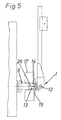
- the bobbin holder 1 with the bobbin 17 is activated by activating Linear drives on the vertical guide 4 lifted off the bobbin stack, to the journal 9 of the bobbin holder and by activating the geared motor 11 rotated by 90 ° so that the core axis 29 of the bobbin 17 is horizontal aligned with the axis of the journal 9 and the bobbin 17 partially on the Bearing pin 9 can be pushed ( Figure 5).
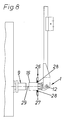
- the mode of operation of the bobbin support 1 when removing an empty core sleeve 16 of the journal 9 of the reel seat according to FIGS. 7 and 8 is as follows:
- the bobbin holder 1 travels with the thrust plate 19 extended in the one angled by 90 ° Rotary position concentric to the core axis 29 with the open jaws 28 of his jaw gripper 26 over the one sitting on the journal 9 Core sleeve 16.
- the actuating cylinder 27 By activating the actuating cylinder 27, the clamping jaws settle 28 against the outer peripheral surface of the core sleeve 16, whereupon the bobbin support 1 retracted by activating the linear drive assigned to the longitudinal guide and pulls the core sleeve 16 from the journal 9.
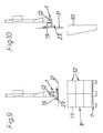
- the method of operation of the bobbin carrier 1 when removing an intermediate layer 31 from the bobbin stack 8 according to FIGS. 9 and 10 is as follows: Before a new bobbin 17 can be transferred from the bobbin stack 8 to the bearing journal 9, an intermediate layer 31 separating two bobbin layers 32 must first be removed.
- the bobbin support 1, with the push plate 1 extended places its suction pads 23 on the intermediate layer 31, which is detected by applying suction air and, according to FIG. 9, is lifted off the bobbin stack 8 by activating the linear drive assigned to the vertical guide 4.
- the bobbin carrier 1 is moved while rotating by 90 ° and the intermediate layer 31 is disposed of by venting the suction pads 23 into a collecting container 33.
Abstract
Description
Der Einsatz von Bobinen-Handhabungsvorrichtungen der eingangs bezeichneten Art hat sich bei einer beispielsweise in der DE-PS 40 41 865 offenbarten Konfiguration der im Verfahrensablauf zusammen wirkenden Komponenten bewährt, bei der flach liegend bzw. mit vertikal ausgerichteter Kernachse an einer Vorratsstation oder auf einer Palette gestapelte Bobinen zu einem maschinenseitigen horizontal ausgerichteten Bobinenaufnahmezapfen überführt werden sollen, indem die erforderliche Umorientierung der Bobinen durch entsprechende Drehantriebe sowie weiträumige Überführungsbewegungen durch entsprechende mehrachsige Linearantriebe realisiert ist.
Nach der EP 0 744 363 A2 ist es bekannt, beim Entpalettisieren von lagenweise gestapelten und durch Zwischenlagen von einander getrennten Packungszuschnitten, derartige Zwischenlagen durch eine spezielle Sauggreiferanordnung zu entfernen.
Eine unabhängig vom jeweiligen Bobinendurchmesser einsetzbare, relativ klein bauende Anordnung besteht nach einer Weiterbildung darin, dass die Backengreifer als radial gegen die Innenfläche einer Kernhülse der Bobine andrückbare Spannstege ausgebildet sind, wobei zweckmäßigerweise nach einem weiteren Vorschlag drei in Winkeln von 120° zueinander verlaufende Spannstege vorgesehen sind. Auf diese Weise lässt sich sehr leicht die um 90° geschwenkte Bobine relativ zur Bobinenaufnahme zentrieren.
Um einerseits die Bobine bei der Überführung sicher zu halten und andererseits eine sichere, exakte Einfädelung an der Bobinenaufnahme zu ermöglichen, ist nach einen zusätzlichen Vorschlag eine parallel zur Kernachse der Bobine relativ zu den inneren Spannstegen im wesentlichen über deren Eingriffslänge in die Kernhülse ausfahrbare Schubplatte vorgesehen. Auf diese Weise kann die Bobine ohne Aktivierung der weiträumige Bewegungen ausführenden Linearantriebe direkt durch einen Antrieb am Bobinenträger auf die Bobinenaufnahme geschoben werden.
Die Multifunktion des Bobinenträgers wird nach einer zusätzlichen Ausgestaltung dadurch ausgeweitet, dass als zusätzliche quer zur Kernachse der Bobine anstellbare Backengreifer an der ausfahrbaren Schubplatte angeordnete, diametral gegen die Außenfläche der Bobine-Kernhülse andrückbare Spannbacken vorgesehen sind. Auf diese Weise können die äußeren Spannbacken bei ausgefahrener Schubplatte unbehindert durch die übrigen Funktionen die Kernhülse am Außenumfang ergreifen und von der Bobinenaufnahme entfernen.
- Figur 1
- eine Seitenansicht eines Bobinenträgers gemäß Erfindung,
- Figur 2
- eine Ansicht auf den Bobinenträger in Richtung des Pfeils Z gemäß Figur 1,
- Figur 3
- eine Draufsicht auf den Bobinenträger,
- Figur 4
- eine Arbeitsstellung des Bobinenträgers bei der Abnahme einer Bobine von einem Vorratsstapel,
- Figuren 5 und 6
- unterschiedliche Arbeitsstellungen des Bobinenträgers beim Aufsetzen einer Bobine auf eine Bobinenaufnahme,
- Figuren 7 und 8
- unterschiedliche Arbeitsstellungen des Bobinenträgers bei der Abnahme einer leeren Bobinen-Kernhülse von der Bobinenaufnahme und
- Figuren 9 und 10
- unterschiedliche Arbeitsstellungen des Bobinenträgers bei der Abnahme einer Zwischenlage vom Bobinen-Vorratsstapel.
Der Bobinenträger 1 ist außerdem mit einer U-förmigen Schubplatte 19 versehen, die mittels eines pneumatischen Stellzylinders 21 und Führungsstangen 22 in Längsrichtung und relativ zu den Spannstegen 14 verschiebbar ist. An der Schubplatte 19 sind vier Sauggreifer 23 angeordnet, an die über einen Pneumatikanschluss 24 Saugluft anlegbar ist.
An der Schubplatte 19 ist zusätzlich ein zweiter Backengreifer 26 angebracht, welcher zwei diametral gegen die Außenfläche der Bobinenkernhülse 16 mittels pneumatischer Stellzylinder 27 andrückbare Spannbacken 28 aufweist.
Der Bobinenträger 1 setzt mit zurückgezogener Schubplatte 19 stirnseitig auf eine Bobine 17 auf, so dass die Spannstege 14 des Backengreifers 13 in den oberen Teil der Kernhülse 16 eintauchen. Durch Aktivieren der Spannzylinderanordnung 18 werden die Spannstege 14 gegen die Innenwand der Kernhülse 16 gespreizt.
Bevor eine neue Bobine 17 vom Bobinenstapel 8 zum Lagerzapfen 9 überführt werden kann, muss zunächst eine zwei Bobinenlagen 32 trennende Zwischenlage 31 entfernt werden. Hierzu setzt der Bobinenträger 1 bei ausgefahrener Schubplatte 1 mit seinen Sauggreifern 23 auf die Zwischenlage 31 auf, die durch Anlegen von Saugluft erfasst und gemäß Figur 9 durch Aktivierung des der Vertikalführung 4 zugeordneten Linearantriebs vom Bobinenstapel 8 abgehoben wird. Der Bobinenträger 1 wird bei gleichzeitiger Drehung um 90° verfahren und die Zwischenlage 31 durch Entlüften der Sauggreifer 23 in einen Auffangbehälter 33 entsorgt.
Claims (6)
- Vorrichtung zum Handhaben von aus gewickelten Materialbahnen, insbesondere Hüllmaterialbahnen für Produkte der Tabak verarbeitenden Industrie gebildete Bobinen, durch Abnahme der Bobinen von einem unter Verwendung von Zwischenlagen gebildeten Bobinenstapel und Überführung der Bobinen an eine einer Verarbeitungseinrichtung zugeordnete Bobinenaufnahme mittels eines um im wesentlichen 90° schwenkbaren und dabei die Kernachse der Bobine aus der vertikalen in die horizontale Lage ausrichtenden Bobinenträgers, dadurch gekennzeichnet, dass der Bobinenträger (1) mit quer zur Kernachse (29) der Bobine (17) anstellbaren Backengreifern (13; 26) sowie mit auf die Zwischenlage (31) aufsetzenden Sauggreifern (23) ausgestattet ist.
- Vorrichtung nach Anspruch 1, dadurch gekennzeichnet, dass die Backengreifer (13) als radial gegen die Innenfläche einer Kernhülse (16) der Bobine (17) andrückbare Spannstege (14) ausgebildet sind.
- Vorrichtung nach Anspruch 2, dadurch gekennzeichnet, dass drei im Winkel von 120° zueinander verlaufende Spannstege (14) vorgesehen sind.
- Vorrichtung nach einem der Ansprüche 1 bis 3, gekennzeichnet durch eine parallel zur Kernachse (29) der Bobine (17) relativ zu den inneren Spannstegen (14) im wesentlichen über deren Eingriffslänge in die Kernhülse (16) ausfahrbare Schubplatte (19).
- Vorrichtung nach Anspruch 4, dadurch gekennzeichnet, dass an der Außenfläche der ausfahrbaren Schubplatte (19) die Sauggreifer (23) angeordnet sind.
- Vorrichtung nach einem der Ansprüche 1 bis 5, dadurch gekennzeichnet, dass als zusätzliche quer zur Kernachse (29) der Bobine (17) anstellbare Backengreifer (26) an der ausfahrbaren Schubplatte (19) angeordnete, diametral gegen die Außenfläche der Bobinen-Kernhülse (16) andrückbare Spannbacken (28) vorgesehen sind.
Applications Claiming Priority (2)
| Application Number | Priority Date | Filing Date | Title |
|---|---|---|---|
| DE10025848 | 2000-05-25 | ||
| DE10025848A DE10025848A1 (de) | 2000-05-25 | 2000-05-25 | Vorrichtung zum Handhaben von Bobinen |
Publications (3)
| Publication Number | Publication Date |
|---|---|
| EP1157952A2 true EP1157952A2 (de) | 2001-11-28 |
| EP1157952A3 EP1157952A3 (de) | 2003-01-15 |
| EP1157952B1 EP1157952B1 (de) | 2005-07-20 |
Family
ID=7643488
Family Applications (1)
| Application Number | Title | Priority Date | Filing Date |
|---|---|---|---|
| EP01111621A Expired - Lifetime EP1157952B1 (de) | 2000-05-25 | 2001-05-12 | Vorrichtung zum Handhaben von Bobinen |
Country Status (8)
| Country | Link |
|---|---|
| US (1) | US6604704B2 (de) |
| EP (1) | EP1157952B1 (de) |
| JP (1) | JP2002020002A (de) |
| CN (1) | CN1236984C (de) |
| AT (1) | ATE299833T1 (de) |
| DE (2) | DE10025848A1 (de) |
| ES (1) | ES2244519T3 (de) |
| PL (1) | PL196740B1 (de) |
Cited By (8)
| Publication number | Priority date | Publication date | Assignee | Title |
|---|---|---|---|---|
| WO2007118537A1 (de) * | 2006-04-11 | 2007-10-25 | Focke & Co. (Gmbh & Co. Kg) | Einrichtung zur handhabung von bobinen aus verpackungsmaterial |
| WO2008010251A1 (en) * | 2006-07-17 | 2008-01-24 | A. Celli Nonwovens S.P.A. | Robot for handling rolls |
| DE102006043810A1 (de) * | 2006-09-13 | 2008-03-27 | Hauni Maschinenbau Ag | Bestimmung einer Bobinenkernmitte bei einer Bobinenhandhabungsvorrichtung |
| WO2016033004A1 (en) * | 2014-08-28 | 2016-03-03 | The Procter & Gamble Company | Improved mandrel |
| WO2016066596A1 (de) * | 2014-10-30 | 2016-05-06 | Krones Aktiengesellschaft | Verfahren und vorrichtung zur handhabung von auf rollen aufgewickeltem flach- und/oder folienmaterial |
| CN106966129A (zh) * | 2017-04-28 | 2017-07-21 | 佛山市南海聚腾环保设备有限公司 | 一种热泵生产线 |
| CN113560441A (zh) * | 2021-09-27 | 2021-10-29 | 南通金德钢结构有限公司 | 一种钢结构输送设备 |
| WO2023051969A1 (de) * | 2021-09-28 | 2023-04-06 | Krones Ag | Mobiler roboter und verfahren zum etikettenrollenwechsel an einem etikettieraggregat |
Families Citing this family (22)
| Publication number | Priority date | Publication date | Assignee | Title |
|---|---|---|---|---|
| ATE402110T1 (de) * | 2001-05-11 | 2008-08-15 | Gd Spa | Verfahren und vorrichtung zum zuführen von verpackungsmaterial zu einer verarbeitungseinheit |
| JP2006199488A (ja) * | 2005-01-24 | 2006-08-03 | Ishida Co Ltd | 包装機 |
| US7546971B2 (en) * | 2005-04-06 | 2009-06-16 | Catbridge Machinery, L.L.C. | System, apparatus and method for unloading rolled material from a supporting structure |
| DE102005060638A1 (de) * | 2005-12-13 | 2007-06-14 | Hauni Maschinenbau Ag | Vorrichtung und Verfahren zum Handhaben von Bobinen innerhalb einer Automatisierungszelle sowie Automatisierungszelle |
| CN102530301A (zh) * | 2010-12-08 | 2012-07-04 | 上海通彩自动化设备有限公司 | 精箔卷料半自动包装生产线 |
| DE102012016479B4 (de) * | 2012-08-17 | 2016-11-03 | Suba Holding Gmbh + Co.Kg | Vorrichtung zum Aufwickeln von bandförmigem Material auf Spulen |
| DE102013110944A1 (de) * | 2013-10-02 | 2015-04-02 | Krones Aktiengesellschaft | Verfahren und Vorrichtung zum Wechseln von Trägereinheiten mit auf Vorratsrollen aufgewickeltem flächigem Verpackungsmaterial innerhalb einer Verpackungsmaschine |
| CN103738530B (zh) * | 2014-01-16 | 2015-07-08 | 无锡恒泰电缆机械制造有限公司 | 热收缩包装机的线圈卡爪循环输送装置 |
| CN103879813B (zh) * | 2014-03-22 | 2017-07-07 | 昆明鼎承科技有限公司 | 纸盘自动供应装置 |
| US9926160B2 (en) * | 2014-08-28 | 2018-03-27 | The Procter & Gamble Company | Robotic unwind stand |
| US9919887B2 (en) * | 2014-08-28 | 2018-03-20 | The Procter & Gamble Company | Web material unwind stand |
| DE102014222167A1 (de) | 2014-10-30 | 2016-05-04 | Krones Aktiengesellschaft | Verfahren und Vorrichtung zur unterbrechungsfreien Handhabung von auf Rollen aufgewickeltem Flach- und/oder Folienmaterial |
| CN107548376B (zh) * | 2015-04-30 | 2020-08-07 | 克朗斯股份公司 | 用于输送、提供和更换带有卷绕在其上的扁平和/或薄膜材料的卷筒的方法和设备 |
| CN106744234B (zh) * | 2017-03-31 | 2018-03-09 | 博格华纳汽车零部件(江苏)有限公司 | V型止锁片及浮动轴承自动夹紧机构 |
| US10662002B2 (en) * | 2017-12-26 | 2020-05-26 | Cynergy Ergonomics, Inc. | Tire manipulator |
| WO2019207436A1 (en) * | 2018-04-26 | 2019-10-31 | I.M.A. Industria Macchine Automatiche S.P.A. | Method for reel changing in automatic machines. |
| CN109081232B (zh) * | 2018-07-11 | 2020-06-19 | 兰天 | 一种机械限位装置 |
| CN108838924A (zh) * | 2018-07-11 | 2018-11-20 | 江苏新惕姆智能装备有限公司 | 滤清器组装夹紧机构及夹紧方法 |
| IT202100018710A1 (it) * | 2021-07-15 | 2023-01-15 | Stefano Petri | Manipolatore per bobine di materiale nastriforme, in particolare per il caricamento di bobine su uno svolgitore |
| CN114229616A (zh) * | 2021-12-10 | 2022-03-25 | 浙江谋皮环保科技有限公司 | 一种用于卸料小车的压实驱动机构 |
| GB2616341A (en) * | 2022-01-14 | 2023-09-06 | Gripple Automation Ltd | Reel alignment control |
| CN114436046A (zh) * | 2022-03-02 | 2022-05-06 | 广州市新兴电缆实业有限公司 | 一种电缆生产加工用收卷设备 |
Citations (5)
| Publication number | Priority date | Publication date | Assignee | Title |
|---|---|---|---|---|
| DE3816164A1 (de) * | 1988-05-11 | 1989-11-23 | Gebald Gregor | Spulenpalettierautomat |
| US5035571A (en) * | 1987-04-28 | 1991-07-30 | W. Schlafhorst Ag & Co. | Assembly for palletizing cross-wound bobbins |
| DE4041865A1 (de) * | 1990-12-27 | 1992-07-02 | Schmermund Maschf Alfred | Verpackungsmaschine |
| DE4341925A1 (de) * | 1993-12-09 | 1995-06-14 | Schlafhorst & Co W | Spulen- und Hülsenhandhabungsgerät |
| DE19538392A1 (de) * | 1995-10-14 | 1997-04-17 | Schlafhorst & Co W | Vorrichtung zur Handhabung von Spulen |
Family Cites Families (12)
| Publication number | Priority date | Publication date | Assignee | Title |
|---|---|---|---|---|
| FR1577456A (de) | 1968-05-24 | 1969-08-08 | ||
| GB2074052A (en) | 1980-04-17 | 1981-10-28 | Hauni Werke Koerber & Co Kg | Apparatus for applying atomized plasticizer to a running web of filamentary filter |
| US4805641A (en) | 1985-07-31 | 1989-02-21 | Korber Ag | Method and apparatus for ascertaining the density of wrapped tobacco fillers and the like |
| DE3631205A1 (de) * | 1986-09-13 | 1988-03-24 | Focke & Co | Vorrichtung zur zufuehrung von verpackungsmaterial-bobinen zu einer verpackungsmaschine |
| DE4008475C2 (de) | 1990-03-16 | 2002-10-10 | Hauni Werke Koerber & Co Kg | Verfahren und Vorrichtung zum Herstellen von Filterzigaretten |
| GB2244983B (en) * | 1990-06-12 | 1994-01-12 | Gd Spa | A device for changing rolls in a machine utilizing strip material |
| DE4024284A1 (de) | 1990-07-31 | 1992-02-06 | Focke & Co | Einrichtung zur versorgung von verpackungsmaschinen mit verpackungsmaterial |
| IT1242891B (it) * | 1990-12-24 | 1994-05-18 | Gd Spa | Metodo e dispositivo per il cambio di bobine in una macchina utilizzatrice di materiale in nastro. |
| DE69208504T2 (de) * | 1991-04-16 | 1996-10-10 | Tabac Fab Reunies Sa | Verfahren und Umladevorrichtung für Bobinen während des Abwicklens |
| IT1253272B (it) | 1991-10-10 | 1995-07-14 | Gd Spa | Dispositivo per la sostituzione di bobine di materiale in nastro in una macchina operatrice |
| IT1278207B1 (it) | 1995-05-18 | 1997-11-17 | Gd Spa | Metodo per l'estrazione di piani di supporto intermedi di pile di prodotti |
| DE19806432A1 (de) * | 1998-02-17 | 1999-08-19 | Focke & Co | Vorrichtung zum Handhaben von Bobinen |
-
2000
- 2000-05-25 DE DE10025848A patent/DE10025848A1/de not_active Withdrawn
-
2001
- 2001-04-20 US US09/838,262 patent/US6604704B2/en not_active Expired - Fee Related
- 2001-05-12 ES ES01111621T patent/ES2244519T3/es not_active Expired - Lifetime
- 2001-05-12 DE DE50106759T patent/DE50106759D1/de not_active Expired - Fee Related
- 2001-05-12 EP EP01111621A patent/EP1157952B1/de not_active Expired - Lifetime
- 2001-05-12 AT AT01111621T patent/ATE299833T1/de not_active IP Right Cessation
- 2001-05-23 JP JP2001153750A patent/JP2002020002A/ja not_active Withdrawn
- 2001-05-24 PL PL347710A patent/PL196740B1/pl unknown
- 2001-05-25 CN CNB011190833A patent/CN1236984C/zh not_active Expired - Fee Related
Patent Citations (5)
| Publication number | Priority date | Publication date | Assignee | Title |
|---|---|---|---|---|
| US5035571A (en) * | 1987-04-28 | 1991-07-30 | W. Schlafhorst Ag & Co. | Assembly for palletizing cross-wound bobbins |
| DE3816164A1 (de) * | 1988-05-11 | 1989-11-23 | Gebald Gregor | Spulenpalettierautomat |
| DE4041865A1 (de) * | 1990-12-27 | 1992-07-02 | Schmermund Maschf Alfred | Verpackungsmaschine |
| DE4341925A1 (de) * | 1993-12-09 | 1995-06-14 | Schlafhorst & Co W | Spulen- und Hülsenhandhabungsgerät |
| DE19538392A1 (de) * | 1995-10-14 | 1997-04-17 | Schlafhorst & Co W | Vorrichtung zur Handhabung von Spulen |
Cited By (12)
| Publication number | Priority date | Publication date | Assignee | Title |
|---|---|---|---|---|
| WO2007118537A1 (de) * | 2006-04-11 | 2007-10-25 | Focke & Co. (Gmbh & Co. Kg) | Einrichtung zur handhabung von bobinen aus verpackungsmaterial |
| US7984603B2 (en) | 2006-04-11 | 2011-07-26 | Focke & Co. (Gmbh & Co. Kg) | Device for handling bobbins of packaging material |
| CN101421175B (zh) * | 2006-04-11 | 2013-05-15 | 佛克有限及两合公司 | 用于处理包装材料卷筒的装置 |
| WO2008010251A1 (en) * | 2006-07-17 | 2008-01-24 | A. Celli Nonwovens S.P.A. | Robot for handling rolls |
| US8353662B2 (en) | 2006-07-17 | 2013-01-15 | A. Celli Nonwovens S.P.A. | Robot for handling rolls |
| DE102006043810A1 (de) * | 2006-09-13 | 2008-03-27 | Hauni Maschinenbau Ag | Bestimmung einer Bobinenkernmitte bei einer Bobinenhandhabungsvorrichtung |
| WO2016033004A1 (en) * | 2014-08-28 | 2016-03-03 | The Procter & Gamble Company | Improved mandrel |
| WO2016066596A1 (de) * | 2014-10-30 | 2016-05-06 | Krones Aktiengesellschaft | Verfahren und vorrichtung zur handhabung von auf rollen aufgewickeltem flach- und/oder folienmaterial |
| CN106966129A (zh) * | 2017-04-28 | 2017-07-21 | 佛山市南海聚腾环保设备有限公司 | 一种热泵生产线 |
| CN113560441A (zh) * | 2021-09-27 | 2021-10-29 | 南通金德钢结构有限公司 | 一种钢结构输送设备 |
| CN113560441B (zh) * | 2021-09-27 | 2021-11-30 | 南通金德钢结构有限公司 | 一种钢结构输送设备 |
| WO2023051969A1 (de) * | 2021-09-28 | 2023-04-06 | Krones Ag | Mobiler roboter und verfahren zum etikettenrollenwechsel an einem etikettieraggregat |
Also Published As
| Publication number | Publication date |
|---|---|
| PL347710A1 (en) | 2001-12-03 |
| CN1325817A (zh) | 2001-12-12 |
| US6604704B2 (en) | 2003-08-12 |
| PL196740B1 (pl) | 2008-01-31 |
| ES2244519T3 (es) | 2005-12-16 |
| US20010045490A1 (en) | 2001-11-29 |
| JP2002020002A (ja) | 2002-01-23 |
| EP1157952B1 (de) | 2005-07-20 |
| DE10025848A1 (de) | 2001-11-29 |
| CN1236984C (zh) | 2006-01-18 |
| DE50106759D1 (de) | 2005-08-25 |
| ATE299833T1 (de) | 2005-08-15 |
| EP1157952A3 (de) | 2003-01-15 |
Similar Documents
| Publication | Publication Date | Title |
|---|---|---|
| EP1157952B1 (de) | Vorrichtung zum Handhaben von Bobinen | |
| EP0616874B1 (de) | Robotarm eines Flächenportalroboters | |
| DE3906922C2 (de) | ||
| EP0296346A2 (de) | Verfahren und Vorrichtung zum lagenweisen Beladen von Paletten | |
| DE102007016727A1 (de) | Verfahren und Vorrichtung zum mehrlagigen Bestapeln eines Trägers | |
| EP0258597A2 (de) | Vorrichting zum Zuführen von Zuschnitten zu einer Verpackungsmaschine | |
| DE102006017379A1 (de) | Einrichtung zur Handhabung von Bobinen aus Verpackungsmaterial | |
| WO2008138947A2 (de) | Verfahren und vorrichtung zum verpacken von getränke-grossgebinden | |
| EP0469298B1 (de) | Einrichtung zur Versorgung von Verpackungsmaschinen mit Verpackungsmaterial | |
| DE102004031301B4 (de) | Vorrichtung zum Einbringen von Zwischenlagen beim Palettieren | |
| DE10355544B4 (de) | Verfahren und Vorrichtung für die Übergabe von Zuschnitten aus Umkartons an eine Weiterverarbeitungseinheit | |
| DE60012921T2 (de) | Verfahren und vorrichtung in bezug auf das umhüllen eines gegenstandes | |
| WO2006037395A1 (de) | Wickeleinsatz für ein transportfähiges kleingebinde, verfahren und vorrichtung zur herstellung eines transportfähigen kleingebindes, transportfähiges kleingebinde | |
| DE4425127A1 (de) | Lageranlage zum Kommissionieren | |
| DE4117473C2 (de) | Verfahren zum Laden von Blattmaterialstapeln in eine Zuführstation einer Verpackungsmaschine und Verwendung einer Vorrichtung zu seiner Durchführung | |
| DE19904443A1 (de) | Verfahren und Vorrichtung zum Zuführen von Packungszuschnitten | |
| DE102009060965A1 (de) | Serviettenfaltvorrichtung | |
| DE19839144A1 (de) | Vorrichtung zum Herstellen und Abtransportieren von Stapeln aus Kunststoffbeuteln, insbesondere Automatenbeuteln | |
| DE102016200581B4 (de) | Verfahren zur Zuförderung, Bereitstellung und zum Austausch von Rollen mit Verpackungsmaterial in einer Verpackungsmaschine | |
| DE2304994C2 (de) | Vorrichtung zum Einbringen von Packungen in Transportbehälter | |
| WO2023011899A2 (de) | Transportvorrichtung für flächige verpackungszuschnitte und verpackungssystem mit einer verpackungsvorrichtung für flächige verpackungszuschnitte | |
| DE3437508A1 (de) | Verfahren und vorrichtung zum automatischen auspacken von dosendeckeln oder dergleichen artikeln aus verpackungen | |
| DE4407324C2 (de) | Robotarm eines Flächenportalroboters | |
| EP2119650B1 (de) | Verfahren und Vorrichtung zur Palettierung von Stückgut | |
| DE3906873C2 (de) |
Legal Events
| Date | Code | Title | Description |
|---|---|---|---|
| PUAI | Public reference made under article 153(3) epc to a published international application that has entered the european phase |
Free format text: ORIGINAL CODE: 0009012 |
|
| AK | Designated contracting states |
Kind code of ref document: A2 Designated state(s): AT BE CH CY DE DK ES FI FR GB GR IE IT LI LU MC NL PT SE TR |
|
| AX | Request for extension of the european patent |
Free format text: AL;LT;LV;MK;RO;SI |
|
| PUAL | Search report despatched |
Free format text: ORIGINAL CODE: 0009013 |
|
| AK | Designated contracting states |
Kind code of ref document: A3 Designated state(s): AT BE CH CY DE DK ES FI FR GB GR IE IT LI LU MC NL PT SE TR |
|
| AX | Request for extension of the european patent |
Free format text: AL;LT;LV;MK;RO;SI |
|
| RIC1 | Information provided on ipc code assigned before grant |
Free format text: 7B 65H 19/12 A, 7B 65H 3/08 B, 7B 65H 5/08 B, 7B 65H 67/06 B, 7B 65G 59/04 B, 7B 65G 47/91 B, 7B 66C 1/54 B, 7B 66C 1/02 B, 7B 65G 61/00 B |
|
| 17P | Request for examination filed |
Effective date: 20030625 |
|
| AKX | Designation fees paid |
Designated state(s): AT BE CH CY DE DK ES FI FR GB GR IE IT LI LU MC NL PT SE TR |
|
| 17Q | First examination report despatched |
Effective date: 20040521 |
|
| RAP1 | Party data changed (applicant data changed or rights of an application transferred) |
Owner name: HAUNI MASCHINENBAU AG |
|
| GRAP | Despatch of communication of intention to grant a patent |
Free format text: ORIGINAL CODE: EPIDOSNIGR1 |
|
| GRAS | Grant fee paid |
Free format text: ORIGINAL CODE: EPIDOSNIGR3 |
|
| GRAA | (expected) grant |
Free format text: ORIGINAL CODE: 0009210 |
|
| AK | Designated contracting states |
Kind code of ref document: B1 Designated state(s): AT BE CH CY DE DK ES FI FR GB GR IE IT LI LU MC NL PT SE TR |
|
| PG25 | Lapsed in a contracting state [announced via postgrant information from national office to epo] |
Ref country code: FI Free format text: LAPSE BECAUSE OF FAILURE TO SUBMIT A TRANSLATION OF THE DESCRIPTION OR TO PAY THE FEE WITHIN THE PRESCRIBED TIME-LIMIT Effective date: 20050720 Ref country code: IE Free format text: LAPSE BECAUSE OF FAILURE TO SUBMIT A TRANSLATION OF THE DESCRIPTION OR TO PAY THE FEE WITHIN THE PRESCRIBED TIME-LIMIT Effective date: 20050720 Ref country code: TR Free format text: LAPSE BECAUSE OF FAILURE TO SUBMIT A TRANSLATION OF THE DESCRIPTION OR TO PAY THE FEE WITHIN THE PRESCRIBED TIME-LIMIT Effective date: 20050720 |
|
| REG | Reference to a national code |
Ref country code: GB Ref legal event code: FG4D Free format text: NOT ENGLISH |
|
| REG | Reference to a national code |
Ref country code: CH Ref legal event code: EP |
|
| GBT | Gb: translation of ep patent filed (gb section 77(6)(a)/1977) |
Effective date: 20050720 |
|
| REG | Reference to a national code |
Ref country code: IE Ref legal event code: FG4D Free format text: LANGUAGE OF EP DOCUMENT: GERMAN |
|
| REF | Corresponds to: |
Ref document number: 50106759 Country of ref document: DE Date of ref document: 20050825 Kind code of ref document: P |
|
| PG25 | Lapsed in a contracting state [announced via postgrant information from national office to epo] |
Ref country code: SE Free format text: LAPSE BECAUSE OF FAILURE TO SUBMIT A TRANSLATION OF THE DESCRIPTION OR TO PAY THE FEE WITHIN THE PRESCRIBED TIME-LIMIT Effective date: 20051020 Ref country code: GR Free format text: LAPSE BECAUSE OF FAILURE TO SUBMIT A TRANSLATION OF THE DESCRIPTION OR TO PAY THE FEE WITHIN THE PRESCRIBED TIME-LIMIT Effective date: 20051020 Ref country code: DK Free format text: LAPSE BECAUSE OF FAILURE TO SUBMIT A TRANSLATION OF THE DESCRIPTION OR TO PAY THE FEE WITHIN THE PRESCRIBED TIME-LIMIT Effective date: 20051020 |
|
| REG | Reference to a national code |
Ref country code: ES Ref legal event code: FG2A Ref document number: 2244519 Country of ref document: ES Kind code of ref document: T3 |
|
| PG25 | Lapsed in a contracting state [announced via postgrant information from national office to epo] |
Ref country code: PT Free format text: LAPSE BECAUSE OF FAILURE TO SUBMIT A TRANSLATION OF THE DESCRIPTION OR TO PAY THE FEE WITHIN THE PRESCRIBED TIME-LIMIT Effective date: 20051221 |
|
| REG | Reference to a national code |
Ref country code: IE Ref legal event code: FD4D |
|
| ET | Fr: translation filed | ||
| PG25 | Lapsed in a contracting state [announced via postgrant information from national office to epo] |
Ref country code: AT Free format text: LAPSE BECAUSE OF NON-PAYMENT OF DUE FEES Effective date: 20060512 |
|
| PLBE | No opposition filed within time limit |
Free format text: ORIGINAL CODE: 0009261 |
|
| STAA | Information on the status of an ep patent application or granted ep patent |
Free format text: STATUS: NO OPPOSITION FILED WITHIN TIME LIMIT |
|
| PG25 | Lapsed in a contracting state [announced via postgrant information from national office to epo] |
Ref country code: MC Free format text: LAPSE BECAUSE OF NON-PAYMENT OF DUE FEES Effective date: 20060531 Ref country code: BE Free format text: LAPSE BECAUSE OF NON-PAYMENT OF DUE FEES Effective date: 20060531 |
|
| 26N | No opposition filed |
Effective date: 20060421 |
|
| BERE | Be: lapsed |
Owner name: HAUNI MASCHINENBAU A.G. Effective date: 20060531 |
|
| PG25 | Lapsed in a contracting state [announced via postgrant information from national office to epo] |
Ref country code: LU Free format text: LAPSE BECAUSE OF NON-PAYMENT OF DUE FEES Effective date: 20060512 |
|
| PGFP | Annual fee paid to national office [announced via postgrant information from national office to epo] |
Ref country code: CH Payment date: 20080526 Year of fee payment: 8 Ref country code: DE Payment date: 20080523 Year of fee payment: 8 Ref country code: ES Payment date: 20080522 Year of fee payment: 8 |
|
| PGFP | Annual fee paid to national office [announced via postgrant information from national office to epo] |
Ref country code: IT Payment date: 20080521 Year of fee payment: 8 |
|
| PGFP | Annual fee paid to national office [announced via postgrant information from national office to epo] |
Ref country code: NL Payment date: 20080528 Year of fee payment: 8 |
|
| PG25 | Lapsed in a contracting state [announced via postgrant information from national office to epo] |
Ref country code: CY Free format text: LAPSE BECAUSE OF FAILURE TO SUBMIT A TRANSLATION OF THE DESCRIPTION OR TO PAY THE FEE WITHIN THE PRESCRIBED TIME-LIMIT Effective date: 20050720 |
|
| PGFP | Annual fee paid to national office [announced via postgrant information from national office to epo] |
Ref country code: FR Payment date: 20080521 Year of fee payment: 8 |
|
| PGFP | Annual fee paid to national office [announced via postgrant information from national office to epo] |
Ref country code: GB Payment date: 20080520 Year of fee payment: 8 |
|
| REG | Reference to a national code |
Ref country code: CH Ref legal event code: PL |
|
| GBPC | Gb: european patent ceased through non-payment of renewal fee |
Effective date: 20090512 |
|
| PG25 | Lapsed in a contracting state [announced via postgrant information from national office to epo] |
Ref country code: CH Free format text: LAPSE BECAUSE OF NON-PAYMENT OF DUE FEES Effective date: 20090531 Ref country code: LI Free format text: LAPSE BECAUSE OF NON-PAYMENT OF DUE FEES Effective date: 20090531 |
|
| NLV4 | Nl: lapsed or anulled due to non-payment of the annual fee |
Effective date: 20091201 |
|
| PG25 | Lapsed in a contracting state [announced via postgrant information from national office to epo] |
Ref country code: NL Free format text: LAPSE BECAUSE OF NON-PAYMENT OF DUE FEES Effective date: 20091201 |
|
| REG | Reference to a national code |
Ref country code: FR Ref legal event code: ST Effective date: 20100129 |
|
| PG25 | Lapsed in a contracting state [announced via postgrant information from national office to epo] |
Ref country code: FR Free format text: LAPSE BECAUSE OF NON-PAYMENT OF DUE FEES Effective date: 20090602 |
|
| PG25 | Lapsed in a contracting state [announced via postgrant information from national office to epo] |
Ref country code: GB Free format text: LAPSE BECAUSE OF NON-PAYMENT OF DUE FEES Effective date: 20090512 |
|
| PG25 | Lapsed in a contracting state [announced via postgrant information from national office to epo] |
Ref country code: DE Free format text: LAPSE BECAUSE OF NON-PAYMENT OF DUE FEES Effective date: 20091201 |
|
| REG | Reference to a national code |
Ref country code: ES Ref legal event code: FD2A Effective date: 20090513 |
|
| PG25 | Lapsed in a contracting state [announced via postgrant information from national office to epo] |
Ref country code: ES Free format text: LAPSE BECAUSE OF NON-PAYMENT OF DUE FEES Effective date: 20090513 |
|
| PG25 | Lapsed in a contracting state [announced via postgrant information from national office to epo] |
Ref country code: IT Free format text: LAPSE BECAUSE OF NON-PAYMENT OF DUE FEES Effective date: 20090512 |