EP1136807A2 - Verfahren und Vorrichtung zum Vorhersagen des Verschleisses eines Reifens - Google Patents
Verfahren und Vorrichtung zum Vorhersagen des Verschleisses eines Reifens Download PDFInfo
- Publication number
- EP1136807A2 EP1136807A2 EP01302421A EP01302421A EP1136807A2 EP 1136807 A2 EP1136807 A2 EP 1136807A2 EP 01302421 A EP01302421 A EP 01302421A EP 01302421 A EP01302421 A EP 01302421A EP 1136807 A2 EP1136807 A2 EP 1136807A2
- Authority
- EP
- European Patent Office
- Prior art keywords
- tire
- temperature
- wear
- tread surface
- surface part
- Prior art date
- Legal status (The legal status is an assumption and is not a legal conclusion. Google has not performed a legal analysis and makes no representation as to the accuracy of the status listed.)
- Granted
Links
- 238000013277 forecasting method Methods 0.000 title claims description 16
- 238000001931 thermography Methods 0.000 claims abstract description 9
- 238000009529 body temperature measurement Methods 0.000 claims description 29
- 238000010438 heat treatment Methods 0.000 claims description 12
- 238000001816 cooling Methods 0.000 claims description 5
- 230000002093 peripheral effect Effects 0.000 description 11
- 238000012360 testing method Methods 0.000 description 8
- 230000000694 effects Effects 0.000 description 5
- 230000000875 corresponding effect Effects 0.000 description 4
- 238000000034 method Methods 0.000 description 4
- 238000005259 measurement Methods 0.000 description 3
- 238000012986 modification Methods 0.000 description 2
- 230000004048 modification Effects 0.000 description 2
- 239000010426 asphalt Substances 0.000 description 1
- 239000000470 constituent Substances 0.000 description 1
- 230000002596 correlated effect Effects 0.000 description 1
- 238000003384 imaging method Methods 0.000 description 1
- 238000011835 investigation Methods 0.000 description 1
- 239000000463 material Substances 0.000 description 1
- 230000000644 propagated effect Effects 0.000 description 1
- 238000005096 rolling process Methods 0.000 description 1
- 238000010008 shearing Methods 0.000 description 1
Images


Classifications
-
- G—PHYSICS
- G01—MEASURING; TESTING
- G01M—TESTING STATIC OR DYNAMIC BALANCE OF MACHINES OR STRUCTURES; TESTING OF STRUCTURES OR APPARATUS, NOT OTHERWISE PROVIDED FOR
- G01M17/00—Testing of vehicles
- G01M17/007—Wheeled or endless-tracked vehicles
- G01M17/02—Tyres
- G01M17/027—Tyres using light, e.g. infrared, ultraviolet or holographic techniques
Definitions
- the present invention relates to methods and apparatus for forecasting tire wear.
- tire wear has been caused by attaching the tires to, and running the tires on, drum test equipment, or installing the tires on actual vehicles and running the tires thereon.
- This invention takes the above situation into account and has a purpose of providing a tire wear forecasting method and apparatus for easily forecasting tire wear.
- the wear on the tire is forecasted based on an increase in the temperature of a tread surface part or based on the temperature of the tread surface part after increasing its temperature, by causing the tire to come into contact with, and to run on, a road surface.
- the increase in temperature of the tread surface part is due to the heat of friction between the tread surface part and the road surface.
- the tread surface part temperature is high after travel since there is a high level of friction and a large amount of wear and, thus, it is possible to easily forecast the tire wear from the temperature increase in the tread surface part or from the temperature of the tread surface part. Additionally, by measuring the temperature of the entire tread surface, it is possible to estimate the wear or the tread of the tire as a whole.
- the aforementioned temperature of the tread surface may, for example, be measured during an interval when, compared to the temperature of the groove in the tread, the temperature of the tread surface is higher.
- the heating due to hysteresis loss will, when viewed from the outside of the tire, appear first in the tread grooves.
- the wear on the tire is the result of friction with the road surface, or in other words, because only the heat from the friction between the road surface and the tire surface is relevant, the heat from the hysteresis loss is an error factor.
- the temperature of the tread groove matches the temperature of the tread surface, it becomes difficult to discern the groove part from the tread surface part when, for example, thermal measurements are taken using thermography.
- the temperature may, for example, be measured within 90 seconds after the tire starts running.
- the tire temperature, before the tire starts running, is preferably lower than the road surface temperature.
- the temperature of the tire is higher than the temperature of the road surface at the time the running is started, the heating due to friction is canceled out, and, in extreme cases, the temperature of the tread surface falls after running is initiated, making it problematic to accurately obtain the increase in temperature. Because of this, it is desirable that the tire temperature be lower than the temperature of the road surface when the running is started.
- the temperature of the tread groove is the same as the temperature of the tread surface, it is difficult to see the boundary between the groove part and the tread surface part from thermal display imaging, making it difficult to forecast the wear of the tread surface.
- the tire may be cooled before running it so that the temperature of the tire is lower than the temperature of the road surface.
- the road surface may, for example, be heated so that it is higher than the temperature of the tire.
- the measured temperature may be corrected based on the length of the tire contact surface.
- the tire tread surface heats up by receiving heat from the road surface due to the contact between the tire tread surface and the road surface.
- the heating due to the contact with the road surface will vary depending on the length of the contact surface with the road surface in the peripheral direction of the tire. Specifically, an increase in temperature when the length of the contact surface is longer (so that the duration of the contact between the road surface and the tread surface is longer) will be greater than when the length of the contact surface is shorter (so that the duration of the contact between the tread surface and the road surface is shorter).
- the tire wear may be forecasted based on the temperature differential calculated by subtracting the temperature of the tread surface part before rotation begins from its temperature during rotation.
- the temperature of the tire tread surface part When the temperature of the tire tread surface part is measured before the commencement of rotation, it is desirable to do so before the tire contacts the road surface.
- the reason for this is that the temperature of the tread surface part that contacts the road surface will change due to the contact between the tire tread surface and the road surface (causing the temperature of one portion of the tread in the peripheral direction to change) if there is a temperature differential between the tire tread surface and the road surface, and the amount by which the temperature changes in the tread surface part that contacts the road surface will be greater when the time of contact between the tire tread surface and the road surface is longer.
- the time between the temperature measurement and the commencement of rotation be as short as possible (particularly if the temperature differential is great).
- the reason for this is that letting the tire sit when there is a temperature differential between the tire and the surrounding air will cause a change in the temperature of the surface of tire, or in other words, in the temperature of the tread surface, and the amount of temperature change in the tire will be larger the longer the tire is allowed to sit.
- the temperature measurement may be performed using a non-contact radiant thermometer, making it possible to perform the temperature measurements with ease even when the tire is rotating.
- a non-contact radiant thermometer is a thermography machine.
- the temperature measurement may be performed using thermography, making it possible to discern visually the temperature of the tire tread surface, or in other words, making it possible to see visually the status of wear of the tread surface.
- the invention is also directed to a tire wear forecasting apparatus that forecasts tire wear based on the temperature of the tread part after causing the tire to come into contact with, and to be run on, a road surface in order to increase the temperature of the tread part.
- the tire wear forecasting apparatus includes a tire support that supports the tire so that it can rotate, a road surface that contacts the tire, means for driving the tire and/or the road surface in order to cause the tire to rotate, and means that measures, without contact, the temperature of the tread surface part and discerns the temperature distribution of the tread surface part from the temperature measurement results.
- a memory device may be provided for recording multiple temperature measurement results, and a calculating device may be provided for calculating the temperature differences of the temperature measurement results from the first temperature measurement and the temperature measurement results from the second temperature measurement at the temperature measurement locations.
- the calculating device calculates the temperature differential (the increase in temperature) of the locations where the temperature is measured, by subtracting the results of the temperature measurement during the first temperature measurement from the results obtained for the temperature measurement during the second temperature measurement.
- the first temperature measurement is, for example, the temperature measurement taken before the running of the tire started.
- the second temperature measurement is the temperature measurement after a specific amount of time has passed after the start of running.
- An inputter can be provided for inputting the length of the tire contact surface, as well as a compensator for correcting at least the temperature measurement results based on the length of the contact surface. For example, when the temperature of the tire is lower than the temperature of the road surface, the compensation coefficient is larger when the contact surface length is short, and smaller when the contact surface length is long.
- the compensator can also perform compensation for temperature increases by multiplying the compensation coefficient based on the contact surface length.
- a display part may be provided whereon at least the temperature measurement results are visible.
- the display part can also make the temperature increases visible.
- a cooling means may be provided for cooling the tire, and/or a heating means may be provided for heating the road surface.
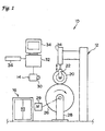
- Fig. 1 is a schematic structural drawing of the tire wear forecasting apparatus of the first example of the embodiment of this invention.
- Figs. 2A, 2B and 2C are respectively, a tire footprint, a graph showing the contact surface length, and a graph showing the compensation coefficients.
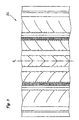
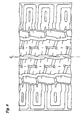
- Fig. 3 shows a tread pattern
- Fig. 4A is an image from a tire that has not been cooled
- Fig. 4B is an image from a tire that has been cooled.
- Fig. 5A is an image of a tire 30 seconds after the start of running
- Fig. 5B is an image of the tire 120 seconds after the start of running.
- Fig. 6 is a graph showing the relationship between tire running time and temperature.
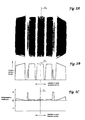
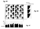
- Fig. 7A is an image taken before compensating for the contact surface length
- Fig. 7B is a graph showing the corresponding temperature distribution
- Fig. 7C is an image after compensating for the contact surface length
- Fig. 7D is a graph of the corresponding temperature distribution
- Fig. 7E is a graph showing the actual amount of wear.
- Fig. 8 shows a tread pattern
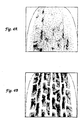
- Fig. 9A is an image of a tire tread shown in Fig. 10;
- Fig. 9B is a graph showing the corresponding temperature distribution in the peripheral direction of the tire;
- Fig. 9C is a graph showing the corresponding temperature distribution in the axial direction of the tire.
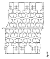
- Fig. 10 shows a tread pattern
- the tire wear forecasting apparatus 10 of this example of the embodiment comprises a drum test apparatus 12, a thermography machine 14, a refrigerator 16, a computer 32, an image display device 34, and a scanner 36.
- the drum test apparatus 12 is equipped with a tire support means 22, that holds the tire 20 so that it can rotate freely, and this tire support means 22 can be moved up and down by a cylinder 24.
- a drum 26 is positioned below the tire support means 22.
- the drum 26 is held by an axle of a support member 28 such that it can rotate freely, and is rotated by a motor 29.
- thermography machine 14 is provided with an infrared camera 30 that is able to detect infrared light that is radiated from the object for which the temperature is to be measured (tire 20 in this embodiment).
- thermography machine 14 the Japan Avionics, Ltd., TVS-8000, is one example of a machine that can be used, although other instruments are also acceptable.
- the infrared camera 30 photographs the tire 20 and sends the temperature information (the results of the temperature measurement) to the computer 32.
- the computer 32 comprises, for example, a CPU (calculating device), a ROM, and RAM (memory devices), etc. It performs calculations on the temperature information from the tire 20 that was photographed by the infrared camera 30 of the thermography machine 14, and displays on the image display device 34 an image of the tire with the temperatures indicated by the density (or differentiating the high and low temperatures by color).
- a CPU calculating device
- ROM read-only memory
- RAM random access memory devices
- the computer 32 is able to store multiple temperature data in memory, and is able to calculate temperature changes between a first photograph and a second photograph by subtracting the temperature data obtained by the first photograph from the temperature data obtained by the second photograph.
- the image display apparatus 34 indicates the temperature when the picture was taken (or the change in temperature) by the density (or by separating the temperatures by color) in the tire image display.
- the computer 32 is connected to a scanner 36.
- the scanner 36 can read in footprint of the tire 20.
- the computer 32 is able to calculate the length of the contact surface in the tire peripheral direction at various positions in the tire axial direction, doing so based on the footprint read by the scanner 36, and can convert this data and store it as a compensation coefficient.
- the computer 32 performs compensation for the temperature information by multiplying the temperature information that has been stored by the compensation coefficient so that it is able to display a tire image based on the corrected temperature information in the image display device 34. Note that the computer 32 compensates for the amount of temperature change by multiplying the compensation coefficient with the temperature change obtained from the calculation, and is able to display a tire image on the image display device 34 based on the corrected temperature change.
- the computer 32 is able to perform various calculations based on the temperature data that has been stored, so that, for example, it is possible to display a temperature distribution along the tire peripheral direction at any given position in the tire axial direction. This may be displayed as a graph on the image display device 34. Further, it is possible to display a graph of the temperature distribution in the tire axial direction at any given location in the tire peripheral direction, the data being displayed on the image display device 34.
- Fig. 7B shows a graph of the temperature distribution in the axial direction of the tire (the average value along the periphery of the tread surface part), and Fig. 7A is an image showing the temperature before compensation of the tire tread that has the tread pattern shown in Fig. 3.
- Fig. 7C shows an image of the temperature after compensation;
- Fig. 7D is a graph showing the temperature distribution in the axial direction of the tire (the average value along the peripheral direction of the tread surface part); and
- Fig. 7E is a graph of the actual wear after 1000 km of travel.
- Fig. 9A shows an image of the temperature of a tire with the tread pattern shown in Fig. 10;
- Fig. 9C is a graph showing the temperature distribution in the crosswise direction across the same tread; and
- Fig. 9B is a graph showing the temperature distribution of the tread in the peripheral direction of the tire.
- the non-uniformity of the temperature in the axial direction of the tire can be seen in the image in Fig. 9A and the graph of Fig. 9C. This can be used to forecast rib punch, edge wear, etc., that will occur in the tire block.
- a tire 20 was cooled before it was run, and although this had an influence on the tire 20 so that the tread surface part could be differentiated, an alternative is to heat only the tread surface of the tire 20 (without cooling the tire 20) to create a temperature differential with the groove part in order to be able to differentiate the tread surface part before taking the photograph of the tire 20.
- a heater heating means
- the tire can be brought into contact with the drum 26 (which has been heated) and rotated for a short period of time.
- the first picture may be taken at that point.
- the tire 20 may be rotated after applying a camber angle, a slip angle, etc., to the tire. By doing so, it is possible to forecast wear under conditions that are similar to actual driving conditions.
- tire 20 was brought into contact with the rotating drum 26 to cause it to rotate; however, tire 20 can be brought into contact with a belt, asphalt, concrete, or other actual road surfaces and caused to rotate in that condition.
- the drum 26 was rotated by the motor 29; however, a motor may be equipped in the tire support 22 to apply a driving force to the tire 20 to cause it to rotate.
- the tire wear forecasting method and tire wear forecasting apparatus of this invention have the superior effect of being able to forecast tire wear easily and rapidly.
Landscapes
- Physics & Mathematics (AREA)
- General Physics & Mathematics (AREA)
- Radiation Pyrometers (AREA)
- Tires In General (AREA)
- Length Measuring Devices With Unspecified Measuring Means (AREA)
Applications Claiming Priority (2)
| Application Number | Priority Date | Filing Date | Title |
|---|---|---|---|
| JP2000077008 | 2000-03-17 | ||
| JP2000077008A JP4357074B2 (ja) | 2000-03-17 | 2000-03-17 | タイヤの摩耗予測方法及びタイヤの摩耗予測装置 |
Publications (3)
| Publication Number | Publication Date |
|---|---|
| EP1136807A2 true EP1136807A2 (de) | 2001-09-26 |
| EP1136807A3 EP1136807A3 (de) | 2003-08-06 |
| EP1136807B1 EP1136807B1 (de) | 2008-07-16 |
Family
ID=18594654
Family Applications (1)
| Application Number | Title | Priority Date | Filing Date |
|---|---|---|---|
| EP01302421A Expired - Lifetime EP1136807B1 (de) | 2000-03-17 | 2001-03-15 | Verfahren und Vorrichtung zum Vorhersagen des Verschleisses eines Reifens |
Country Status (5)
| Country | Link |
|---|---|
| US (1) | US6883962B2 (de) |
| EP (1) | EP1136807B1 (de) |
| JP (1) | JP4357074B2 (de) |
| DE (1) | DE60134806D1 (de) |
| ES (1) | ES2309036T3 (de) |
Cited By (4)
| Publication number | Priority date | Publication date | Assignee | Title |
|---|---|---|---|---|
| RU2224989C1 (ru) * | 2002-05-23 | 2004-02-27 | Алтайский государственный технический университет им. И.И. Ползунова | Устройство для измерения проскальзывания протектора шины относительно опорной поверхности |
| CN104655510A (zh) * | 2015-02-13 | 2015-05-27 | 中铁第一勘察设计院集团有限公司 | 高速铁路轨道测量仪测量轮耐磨性测试装置 |
| EP3062091A4 (de) * | 2013-11-15 | 2017-06-28 | Sumitomo Rubber Industries, Ltd. | Verfahren zur überwachung der verformung eines elastischen materials und abbildungsvorrichtung zur projektion von bildern des elastischen materials |
| EP2583247A4 (de) * | 2010-06-15 | 2017-12-06 | Compagnie Générale des Etablissements Michelin | Erkennung von anomalien auf reifenflächen |
Families Citing this family (48)
| Publication number | Priority date | Publication date | Assignee | Title |
|---|---|---|---|---|
| JP4488639B2 (ja) * | 2001-03-06 | 2010-06-23 | 財団法人鉄道総合技術研究所 | 障害警報装置 |
| ATE410317T1 (de) * | 2001-07-24 | 2008-10-15 | Tuev Automotive Gmbh Unternehm | Verfahren und system zum überwachen des betriebs eines fahrzeugreifens sowie fahrzeugreifen |
| DE60227979D1 (de) * | 2001-11-02 | 2008-09-11 | Michelin Soc Tech | Verfahren und vorrichtung zum messen von verschleiss eines fahrzeugmontierten reifens |
| JP4397327B2 (ja) * | 2002-08-12 | 2010-01-13 | 株式会社ブリヂストン | ランフラット状態で継続走行するランフラットタイヤの走行余命を判定する、方法及び装置 |
| ATE546327T1 (de) * | 2003-10-31 | 2012-03-15 | Pirelli | Verfahren und vorrichtung zur ermittlung der fahrflächenrauhigkeit eines reifens |
| JP4617690B2 (ja) * | 2004-03-22 | 2011-01-26 | 横浜ゴム株式会社 | タイヤ表面温度の監視システム及びその監視方法及びその監視プログラム及びその監視画面表示方法 |
| US7269997B2 (en) * | 2004-06-03 | 2007-09-18 | Snap-On Incorporated | Non-contact method and system for tire analysis |
| JP4591218B2 (ja) * | 2005-06-08 | 2010-12-01 | 横浜ゴム株式会社 | 摩擦試験機 |
| JP2007017423A (ja) * | 2005-06-08 | 2007-01-25 | Yokohama Rubber Co Ltd:The | 摩擦試験方法及び摩擦試験機 |
| US7124629B1 (en) * | 2005-09-01 | 2006-10-24 | The Goodyear Tire & Rubber Company | Prediction of internal rib irregular wear via rib edge lateral slip |
| US8985848B2 (en) * | 2006-06-30 | 2015-03-24 | Bdc Capital Inc. | Thermal inspection system |
| KR100796332B1 (ko) | 2006-08-16 | 2008-01-21 | 한국타이어 주식회사 | 타이어의 동하중 반경 검사방법 |
| US8478480B2 (en) * | 2006-10-27 | 2013-07-02 | International Electronic Machines Corp. | Vehicle evaluation using infrared data |
| JP4905167B2 (ja) * | 2007-02-07 | 2012-03-28 | 横浜ゴム株式会社 | タイヤ凹凸形状測定装置、タイヤ凹凸形状判定システム、タイヤ凹凸形状測定方法、およびタイヤ凹凸形状判定方法 |
| JP5114997B2 (ja) * | 2007-03-28 | 2013-01-09 | 横浜ゴム株式会社 | タイヤ試験装置およびタイヤ試験方法 |
| WO2009155591A1 (en) * | 2008-06-20 | 2009-12-23 | Test Devices Inc. | Systems and methods for producing thermal mechanical fatigue on gas turbine rotors in a spin test environment |
| CA2848272C (en) * | 2008-10-22 | 2017-11-14 | International Electronic Machines Corp. | Thermal imaging-based vehicle analysis |
| JP5445738B2 (ja) * | 2009-03-09 | 2014-03-19 | 横浜ゴム株式会社 | タイヤ撮影用補助装置 |
| JP5750820B2 (ja) * | 2009-09-29 | 2015-07-22 | Jfeスチール株式会社 | 鉄損測定方法 |
| US8347703B2 (en) * | 2011-02-11 | 2013-01-08 | Bridgestone Americas Tire Operations, Llc | Tire chip and tear test apparatus and method |
| US20130278771A1 (en) * | 2011-06-10 | 2013-10-24 | Flir Systems, Inc. | Systems and methods for monitoring vehicle wheel assembly |
| US9085205B2 (en) * | 2012-12-21 | 2015-07-21 | Continental Automotive Systems, Inc. | Tire tread temperature sensor and diagnostics for in-vehicle display |
| US9079461B2 (en) | 2013-03-14 | 2015-07-14 | The Goodyear Tire & Rubber Company | Predictive peer-based tire health monitoring |
| EP3028029B1 (de) * | 2013-08-01 | 2020-05-27 | MTS Systems Corporation | Reifen prüfvorrichtung |
| JP6330462B2 (ja) * | 2014-05-09 | 2018-05-30 | 横浜ゴム株式会社 | ゴムまたはエラストマーの動摩擦係数の測定方法および装置 |
| JP6334278B2 (ja) * | 2014-06-06 | 2018-05-30 | 株式会社ブリヂストン | 計測装置 |
| US9376118B2 (en) | 2014-07-08 | 2016-06-28 | The Goodyear Tire & Rubber Company | Assessment of tire condition based on a tire health parameter |
| US9636956B2 (en) | 2014-11-04 | 2017-05-02 | The Goodyear Tire & Rubber Company | Wheel diagnostic monitoring |
| CN105856985B (zh) * | 2015-02-09 | 2019-07-26 | 斯耐普昂设备有限公司 | 至少一个车辆车轮或轮胎的提升装置及其磨损状态检测器 |
| JP6558857B2 (ja) * | 2016-04-06 | 2019-08-14 | 株式会社ブリヂストン | 転がり抵抗測定方法および装置 |
| KR101999645B1 (ko) | 2017-11-20 | 2019-07-12 | 금호타이어 주식회사 | 열화상 카메라를 이용한 실차 타이어 불규칙 마모 및 내구 예측 방법 |
| JP7011452B2 (ja) * | 2017-12-07 | 2022-01-26 | Toyo Tire株式会社 | タイヤ騒音試験装置及び方法 |
| JP7011453B2 (ja) * | 2017-12-07 | 2022-01-26 | Toyo Tire株式会社 | タイヤ騒音試験装置及び方法 |
| IT201800003276A1 (it) * | 2018-03-05 | 2019-09-05 | Bridgestone Europe Nv Sa | Apparato per l'analisi del comportamento di uno pneumatico all'interfaccia con il suolo |
| EP3814152B1 (de) | 2018-06-29 | 2025-08-13 | Bridgestone Americas, Inc. | Strukturen und verfahren zur integration von laufflächensensoren |
| WO2020086698A1 (en) * | 2018-10-25 | 2020-04-30 | Tyrata, Inc. | Methods and systems used to measure tire treads |
| CN110231182A (zh) * | 2019-06-14 | 2019-09-13 | 青岛科技大学 | 室内轮胎磨耗测试方法 |
| US11614317B2 (en) | 2019-06-21 | 2023-03-28 | Tyrata, Inc. | Methods providing enhanced material thickness sensing with capacitive sensors using inductance-generated resonance and related devices |
| CN110455556A (zh) * | 2019-08-08 | 2019-11-15 | 中国汽车技术研究中心有限公司 | 一种用于轮胎动力学特性测试的试验平台 |
| CN110375998A (zh) * | 2019-08-22 | 2019-10-25 | 亿科检测认证有限公司 | 一种轮胎耐磨性检测装置 |
| US11981163B2 (en) | 2019-08-30 | 2024-05-14 | The Goodyear Tire & Rubber Company | Tire wear state estimation system and method employing footprint shape factor |
| AU2020220054A1 (en) * | 2019-08-30 | 2021-03-18 | The Goodyear Tire & Rubber Company | Tire wear state estimation system and method employing footprint length |
| AU2020220060A1 (en) | 2019-08-30 | 2021-03-18 | The Goodyear Tire & Rubber Company | Method for extracting changes in tyre characteristics |
| US11865875B2 (en) | 2020-08-18 | 2024-01-09 | The Goodyear Tire & Rubber Company | Tire high temperature forecasting system |
| US12220946B2 (en) | 2021-06-08 | 2025-02-11 | The Goodyear Tire & Rubber Company | Tire replacement forecasting system and method |
| US12263704B2 (en) | 2021-12-06 | 2025-04-01 | The Goodyear Tire & Rubber Company | Tire irregular wear detection system and method |
| CN114264567B (zh) * | 2022-01-05 | 2024-03-08 | 中国人民解放军陆军装甲兵学院 | 一种试验安全监控系统 |
| US12589618B2 (en) | 2022-11-11 | 2026-03-31 | The Goodyear Tire & Rubber Company | Method and system for monitoring tire inflation pressure |
Family Cites Families (29)
| Publication number | Priority date | Publication date | Assignee | Title |
|---|---|---|---|---|
| US3549986A (en) * | 1967-04-10 | 1970-12-22 | Magnaflux Corp | Microwave flaw detection system having horns positioned with their polarization directions transverse to each other |
| AT278405B (de) * | 1967-09-07 | 1970-01-26 | Semperit Ag | Verfahren zur Untersuchung von Mustern für Reifenprofile |
| US3854336A (en) * | 1972-01-26 | 1974-12-17 | Monsanto Co | Method for detecting thermal changes on a surface |
| US3807226A (en) * | 1972-11-29 | 1974-04-30 | Department Of Transportation | Non-linear amplification technique for improving signal to noise contrast |
| US3835591A (en) * | 1973-05-14 | 1974-09-17 | Goodrich Co B F | Method and apparatus for correcting dimensional variation in a rotating tire |
| GB8318699D0 (en) * | 1983-07-11 | 1983-08-10 | Marconi Avionics | Tyre temperature measurement |
| DE3932674A1 (de) * | 1989-09-29 | 1991-04-11 | Hofmann Gmbh & Co Kg Maschinen | Verfahren und vorrichtung zum pruefen von luftreifen, insbesondere kraftfahrzeugreifen |
| JPH0749938B2 (ja) * | 1989-11-02 | 1995-05-31 | 住友ゴム工業株式会社 | タイヤ接地面観測装置及び観測方法 |
| US4995197A (en) * | 1990-01-29 | 1991-02-26 | Shieh Chiung Huei | Method of abrading |
| US5216372A (en) * | 1991-07-29 | 1993-06-01 | Colorado State University Research Foundation | Microwave steel belt location sensor for tires |
| US5245867A (en) * | 1991-12-16 | 1993-09-21 | Bridgestone Corporation | Method and apparatus for measuring tire parameters |
| US5483827A (en) * | 1994-06-03 | 1996-01-16 | Computer Methods Corporation | Active integrated circuit transponder and sensor apparatus for sensing and transmitting vehicle tire parameter data |
| IT1277253B1 (it) * | 1995-10-09 | 1997-11-05 | Pirelli | Metodo per la previsione ed il controllo dell'usura del battistrada in un pneumatico e relativo pneumatico |
| JP3668335B2 (ja) * | 1996-04-22 | 2005-07-06 | 株式会社ブリヂストン | タイヤの不規則摩耗の予測方法 |
| US5743645A (en) * | 1996-06-12 | 1998-04-28 | Longacre Automotive Racing Products | Tire pyrometer |
| KR100189649B1 (ko) * | 1996-10-14 | 1999-06-01 | 신형인 | 타이어 트레드의 마모 평가 방법 |
| IT1290083B1 (it) * | 1997-03-14 | 1998-10-19 | Pirelli | Pneumatico a bassa temperatura d'esercizio |
| US6100923A (en) * | 1997-03-20 | 2000-08-08 | The United States Of America As Represented By The Secretary Of The Army | Method of infrared imaging |
| JP3254166B2 (ja) * | 1997-05-16 | 2002-02-04 | 住友ゴム工業株式会社 | 重荷重用ラジアルタイヤ |
| US5909171A (en) * | 1997-07-17 | 1999-06-01 | Meritor Heavy Vehicle Systems, L L C | Temperature sensing brake lining wear indicator |
| DE19736769C1 (de) * | 1997-08-23 | 1998-10-15 | Continental Ag | Vorrichtung und Verfahren zur Ermittlung und/oder zur Darstellung der in der Lauffläche eines Reifens beim Abrollen erzeugten Temperatur |
| US6111643A (en) * | 1997-10-28 | 2000-08-29 | Reliance Electric Industrial Company | Apparatus, system and method for determining wear of an article |
| JP3320653B2 (ja) * | 1998-05-08 | 2002-09-03 | 株式会社ブリヂストン | タイヤ摩耗寿命予測方法 |
| JP4041582B2 (ja) * | 1998-06-17 | 2008-01-30 | 三井化学株式会社 | ベンゾ〔k〕フルオランテン誘導体 |
| JP3961163B2 (ja) * | 1999-01-28 | 2007-08-22 | 横浜ゴム株式会社 | タイヤ検査装置及びタイヤ検査方法 |
| JP2001208618A (ja) * | 2000-01-27 | 2001-08-03 | Bridgestone Corp | タイヤの内部温度測定方法及びタイヤの内部温度測定装置 |
| JP3769459B2 (ja) * | 2000-10-13 | 2006-04-26 | 株式会社豊田中央研究所 | タイヤバースト予測装置 |
| US6546791B2 (en) * | 2001-08-08 | 2003-04-15 | Bridgestone/Firestone North American Tire, Llc | Indoor hydroplaning test apparatus and method |
| US20030214394A1 (en) * | 2002-05-17 | 2003-11-20 | Behrendsen Paul Alfred | Method and apparatus for sensing tire performance and wear |
-
2000
- 2000-03-17 JP JP2000077008A patent/JP4357074B2/ja not_active Expired - Fee Related
-
2001
- 2001-03-15 ES ES01302421T patent/ES2309036T3/es not_active Expired - Lifetime
- 2001-03-15 EP EP01302421A patent/EP1136807B1/de not_active Expired - Lifetime
- 2001-03-15 DE DE60134806T patent/DE60134806D1/de not_active Expired - Lifetime
- 2001-03-19 US US09/810,603 patent/US6883962B2/en not_active Expired - Fee Related
Non-Patent Citations (1)
| Title |
|---|
| None |
Cited By (6)
| Publication number | Priority date | Publication date | Assignee | Title |
|---|---|---|---|---|
| RU2224989C1 (ru) * | 2002-05-23 | 2004-02-27 | Алтайский государственный технический университет им. И.И. Ползунова | Устройство для измерения проскальзывания протектора шины относительно опорной поверхности |
| EP2583247A4 (de) * | 2010-06-15 | 2017-12-06 | Compagnie Générale des Etablissements Michelin | Erkennung von anomalien auf reifenflächen |
| EP3062091A4 (de) * | 2013-11-15 | 2017-06-28 | Sumitomo Rubber Industries, Ltd. | Verfahren zur überwachung der verformung eines elastischen materials und abbildungsvorrichtung zur projektion von bildern des elastischen materials |
| US10274438B2 (en) | 2013-11-15 | 2019-04-30 | Sumitomo Rubber Industries, Ltd. | Method for observing deformation of elastic material and apparatus for capturing projection image of elastic material |
| CN104655510A (zh) * | 2015-02-13 | 2015-05-27 | 中铁第一勘察设计院集团有限公司 | 高速铁路轨道测量仪测量轮耐磨性测试装置 |
| CN104655510B (zh) * | 2015-02-13 | 2017-08-11 | 中铁第一勘察设计院集团有限公司 | 高速铁路轨道测量仪测量轮耐磨性测试装置 |
Also Published As
| Publication number | Publication date |
|---|---|
| DE60134806D1 (de) | 2008-08-28 |
| EP1136807A3 (de) | 2003-08-06 |
| US20010022802A1 (en) | 2001-09-20 |
| US6883962B2 (en) | 2005-04-26 |
| JP2001264041A (ja) | 2001-09-26 |
| EP1136807B1 (de) | 2008-07-16 |
| JP4357074B2 (ja) | 2009-11-04 |
| ES2309036T3 (es) | 2008-12-16 |
Similar Documents
| Publication | Publication Date | Title |
|---|---|---|
| US6883962B2 (en) | Tire wear forecasting method and apparatus | |
| EP0837308B1 (de) | Vorrichtung und zugehörige Verfahren zum automatischen Prüfen und Analysieren von Reifen | |
| KR102866939B1 (ko) | 타이어의 마모 및 수명의 종료를 예측하기 위한 모델 | |
| JP7271109B2 (ja) | タイヤ保守管理装置およびタイヤ保守システム | |
| EP2793013A1 (de) | Automobil-Wartungs-Werkstattvorrichtung mit Mitteln zur Bestimmung des Rollwiderstandsbeiwertes eines Reifens | |
| KR101108250B1 (ko) | 타이어 마모 측정 장치 | |
| EP0729018A2 (de) | Verfahren und Apparat zum Testen der Bremsen | |
| EP1767422B1 (de) | Verfahren und Vorrichtung zur Abschätzung des Radverhaltens bei Kurvenfahrt | |
| US4364267A (en) | Method and apparatus for correlating tire inflation pressure and load | |
| JP4030572B2 (ja) | 車両制動距離予測装置および車両制動距離予測方法 | |
| Sakai | Measurement and visualization of the contact pressure distribution of rubber disks and tires | |
| JP2016075503A (ja) | タイヤの転がり抵抗の評価用方法 | |
| JP2015016756A (ja) | トレッドゴムの摩擦係数の算出方法、タイヤ特性の算出方法、トレッドゴムの摩擦係数の算出装置、及びプログラム | |
| GB2555604A (en) | Vehicle inspection methods and apparatus | |
| JP6288762B2 (ja) | タイヤブロックの摩耗の予測方法 | |
| JP7454370B2 (ja) | 転がり抵抗係数推定方法 | |
| US20220082460A1 (en) | Stress analysis device for moving body | |
| JPWO2005075959A1 (ja) | 摩擦係数推定方法及び装置 | |
| US20240393213A1 (en) | Prediction method for durability of tire | |
| KR20160101768A (ko) | 공기압 타이어의 실내주행 시험장치 및 그 시험측정 방법 | |
| JP2001208618A (ja) | タイヤの内部温度測定方法及びタイヤの内部温度測定装置 | |
| US20260103178A1 (en) | Vehicle Brake Disc Temperature Monitoring Method and Apparatus | |
| JP7801557B2 (ja) | タイヤのひずみ測定装置及び測定方法 | |
| JPH09297081A (ja) | 車両用ブレーキテスタ | |
| JP2026070494A (ja) | 車両ブレーキディスク温度監視方法及び装置 |
Legal Events
| Date | Code | Title | Description |
|---|---|---|---|
| PUAI | Public reference made under article 153(3) epc to a published international application that has entered the european phase |
Free format text: ORIGINAL CODE: 0009012 |
|
| AK | Designated contracting states |
Kind code of ref document: A2 Designated state(s): AT BE CH CY DE DK ES FI FR GB GR IE IT LI LU MC NL PT SE TR |
|
| AX | Request for extension of the european patent |
Free format text: AL;LT;LV;MK;RO;SI |
|
| PUAL | Search report despatched |
Free format text: ORIGINAL CODE: 0009013 |
|
| AK | Designated contracting states |
Designated state(s): AT BE CH CY DE DK ES FI FR GB GR IE IT LI LU MC NL PT SE TR |
|
| AX | Request for extension of the european patent |
Extension state: AL LT LV MK RO SI |
|
| 17P | Request for examination filed |
Effective date: 20040204 |
|
| AKX | Designation fees paid |
Designated state(s): DE ES FR GB IT |
|
| GRAP | Despatch of communication of intention to grant a patent |
Free format text: ORIGINAL CODE: EPIDOSNIGR1 |
|
| GRAS | Grant fee paid |
Free format text: ORIGINAL CODE: EPIDOSNIGR3 |
|
| GRAA | (expected) grant |
Free format text: ORIGINAL CODE: 0009210 |
|
| AK | Designated contracting states |
Kind code of ref document: B1 Designated state(s): DE ES FR GB IT |
|
| REG | Reference to a national code |
Ref country code: GB Ref legal event code: FG4D |
|
| REF | Corresponds to: |
Ref document number: 60134806 Country of ref document: DE Date of ref document: 20080828 Kind code of ref document: P |
|
| REG | Reference to a national code |
Ref country code: ES Ref legal event code: FG2A Ref document number: 2309036 Country of ref document: ES Kind code of ref document: T3 |
|
| PLBE | No opposition filed within time limit |
Free format text: ORIGINAL CODE: 0009261 |
|
| STAA | Information on the status of an ep patent application or granted ep patent |
Free format text: STATUS: NO OPPOSITION FILED WITHIN TIME LIMIT |
|
| 26N | No opposition filed |
Effective date: 20090417 |
|
| PGFP | Annual fee paid to national office [announced via postgrant information from national office to epo] |
Ref country code: ES Payment date: 20130314 Year of fee payment: 13 |
|
| PGFP | Annual fee paid to national office [announced via postgrant information from national office to epo] |
Ref country code: DE Payment date: 20140328 Year of fee payment: 14 |
|
| PGFP | Annual fee paid to national office [announced via postgrant information from national office to epo] |
Ref country code: FR Payment date: 20140319 Year of fee payment: 14 Ref country code: IT Payment date: 20140326 Year of fee payment: 14 |
|
| PGFP | Annual fee paid to national office [announced via postgrant information from national office to epo] |
Ref country code: GB Payment date: 20140319 Year of fee payment: 14 |
|
| REG | Reference to a national code |
Ref country code: DE Ref legal event code: R082 Ref document number: 60134806 Country of ref document: DE Representative=s name: MARKS & CLERK (LUXEMBOURG) LLP, LU |
|
| REG | Reference to a national code |
Ref country code: FR Ref legal event code: CA Effective date: 20140812 |
|
| REG | Reference to a national code |
Ref country code: DE Ref legal event code: R081 Ref document number: 60134806 Country of ref document: DE Owner name: BRIDGESTONE CORPORATION, JP Free format text: FORMER OWNER: BRIDGESTONE CORP., TOKIO/TOKYO, JP Effective date: 20140828 Ref country code: DE Ref legal event code: R082 Ref document number: 60134806 Country of ref document: DE Representative=s name: MARKS & CLERK (LUXEMBOURG) LLP, LU Effective date: 20140828 |
|
| REG | Reference to a national code |
Ref country code: DE Ref legal event code: R119 Ref document number: 60134806 Country of ref document: DE |
|
| GBPC | Gb: european patent ceased through non-payment of renewal fee |
Effective date: 20150315 |
|
| PG25 | Lapsed in a contracting state [announced via postgrant information from national office to epo] |
Ref country code: IT Free format text: LAPSE BECAUSE OF NON-PAYMENT OF DUE FEES Effective date: 20150315 |
|
| REG | Reference to a national code |
Ref country code: FR Ref legal event code: ST Effective date: 20151130 |
|
| PG25 | Lapsed in a contracting state [announced via postgrant information from national office to epo] |
Ref country code: DE Free format text: LAPSE BECAUSE OF NON-PAYMENT OF DUE FEES Effective date: 20151001 Ref country code: GB Free format text: LAPSE BECAUSE OF NON-PAYMENT OF DUE FEES Effective date: 20150315 |
|
| PG25 | Lapsed in a contracting state [announced via postgrant information from national office to epo] |
Ref country code: FR Free format text: LAPSE BECAUSE OF NON-PAYMENT OF DUE FEES Effective date: 20150331 |
|
| REG | Reference to a national code |
Ref country code: ES Ref legal event code: FD2A Effective date: 20160426 |
|
| PG25 | Lapsed in a contracting state [announced via postgrant information from national office to epo] |
Ref country code: ES Free format text: LAPSE BECAUSE OF NON-PAYMENT OF DUE FEES Effective date: 20150316 |