EP0837308B1 - Vorrichtung und zugehörige Verfahren zum automatischen Prüfen und Analysieren von Reifen - Google Patents
Vorrichtung und zugehörige Verfahren zum automatischen Prüfen und Analysieren von Reifen Download PDFInfo
- Publication number
- EP0837308B1 EP0837308B1 EP97117742A EP97117742A EP0837308B1 EP 0837308 B1 EP0837308 B1 EP 0837308B1 EP 97117742 A EP97117742 A EP 97117742A EP 97117742 A EP97117742 A EP 97117742A EP 0837308 B1 EP0837308 B1 EP 0837308B1
- Authority
- EP
- European Patent Office
- Prior art keywords
- tire
- load
- foot print
- deflection
- processor
- Prior art date
- Legal status (The legal status is an assumption and is not a legal conclusion. Google has not performed a legal analysis and makes no representation as to the accuracy of the status listed.)
- Expired - Lifetime
Links
- 238000012360 testing method Methods 0.000 title claims description 77
- 238000000034 method Methods 0.000 title claims description 29
- 238000011068 loading method Methods 0.000 claims description 34
- 238000004458 analytical method Methods 0.000 claims description 13
- 238000010168 coupling process Methods 0.000 claims description 7
- 238000005859 coupling reaction Methods 0.000 claims description 7
- 238000013507 mapping Methods 0.000 claims description 5
- 230000008878 coupling Effects 0.000 claims description 3
- 238000012544 monitoring process Methods 0.000 claims description 2
- 230000001746 atrial effect Effects 0.000 claims 1
- 238000013461 design Methods 0.000 description 6
- 238000005286 illumination Methods 0.000 description 3
- 238000003384 imaging method Methods 0.000 description 3
- 238000005299 abrasion Methods 0.000 description 2
- 230000009286 beneficial effect Effects 0.000 description 2
- 238000012937 correction Methods 0.000 description 2
- 238000004519 manufacturing process Methods 0.000 description 2
- 230000007246 mechanism Effects 0.000 description 2
- 230000008569 process Effects 0.000 description 2
- 238000000611 regression analysis Methods 0.000 description 2
- 239000000523 sample Substances 0.000 description 2
- 238000012546 transfer Methods 0.000 description 2
- 239000011800 void material Substances 0.000 description 2
- 230000009471 action Effects 0.000 description 1
- 238000012863 analytical testing Methods 0.000 description 1
- 230000006399 behavior Effects 0.000 description 1
- 238000009530 blood pressure measurement Methods 0.000 description 1
- 230000008859 change Effects 0.000 description 1
- 238000004891 communication Methods 0.000 description 1
- 238000013480 data collection Methods 0.000 description 1
- 238000012938 design process Methods 0.000 description 1
- 230000001627 detrimental effect Effects 0.000 description 1
- 238000011161 development Methods 0.000 description 1
- 238000009826 distribution Methods 0.000 description 1
- 238000011156 evaluation Methods 0.000 description 1
- 238000013213 extrapolation Methods 0.000 description 1
- 230000006870 function Effects 0.000 description 1
- 239000011521 glass Substances 0.000 description 1
- 230000001788 irregular Effects 0.000 description 1
- 239000000463 material Substances 0.000 description 1
- 238000005259 measurement Methods 0.000 description 1
- 238000003860 storage Methods 0.000 description 1
Images


Classifications
-
- G—PHYSICS
- G01—MEASURING; TESTING
- G01M—TESTING STATIC OR DYNAMIC BALANCE OF MACHINES OR STRUCTURES; TESTING OF STRUCTURES OR APPARATUS, NOT OTHERWISE PROVIDED FOR
- G01M17/00—Testing of vehicles
- G01M17/007—Wheeled or endless-tracked vehicles
- G01M17/02—Tyres
- G01M17/027—Tyres using light, e.g. infrared, ultraviolet or holographic techniques
Definitions
- the invention herein resides in the art of techniques and apparatus for testing pneumatic tires. More particularly, the invention relates to such methods and apparatus for performing both tire foot print tests and load-deflection tests, wherein the data collected from these tests is presented in several different formats. Specifically, the invention relates to such methods and apparatus for analyzing a tire by either capturing a digital image of the tire foot print or by extrapolating load-deflection curves of the tire.
- Tire testing machines are also known to generate load-deflection curves which are useful in predicting tire performance.
- a load-deflection curve indicates how much a tire is deflected under a given load at a given inflation pressure.
- Prior art machines require that test data must be generated for five or more inflation pressures. Generating this load-deflection data is a time-consuming process that extends the time and cost of testing a tire.
- Another aspect of the present invention is to provide an apparatus which includes a frame that slidably receives a test pod that is coupled with the tire to perform a plurality of tests.
- Still a further aspect of the present invention is to provide a tire spindle with the necessary mechanical linkage to impart a camber upon the tire during testing.
- Still yet another aspect of the present invention is to provide a motor connected to the tire spindle to selectively rotate the tire into various testing positions.
- An additional aspect of the present invention is to provide a load plate connected to the tire spindle to couple the tire to the test pod.
- Still yet another aspect of the present invention is to provide a load cell connected to the load plate to determine the amount of radial load imparted on the tire coupled to the test pod.
- Yet a further aspect of the present invention is to provide a deflection cell that monitors the amount of deflection of the tire as a load is imparted thereon.
- Still yet another aspect of the present invention is to provide an inflation pressure source connected to the tire so that a plurality of inflation pressures can be provided to the tire as it is coupled to the test pod.
- Another aspect of the present invention is to provide a processor which controls the various aforementioned components of the apparatus.
- Still another aspect of the present invention is to provide the test pod with a transparent plate and a cover plate slidable thereover, wherein the transparent plate is employed to obtain foot print test data and the slidable cover plate is employed to obtain load-deflection data.
- Still yet another aspect of the present invention is to provide a camera within the test pod to capture a digital image of the tire coupled to the transparent plate.
- An even further aspect of the present invention is wherein the processor performs various tests on the digital image obtained by the camera.
- processor converts the digital image into a gray-scale image and employs a calibration operation to correlate the gray values to contact pressure values.
- Still a further aspect of the present invention is wherein the processor extrapolates load-deflection curves from at least two load-deflection curves generated when the tire is coupled to the test pod.
- an apparatus for testing tires comprising: a frame (12); a loading plate (70) mounted within said frame (12); a tire spindle (94) extending from said loading plate (70), said tire spindle (94) receiving a tire (11) to be tested; a test pod (42); and a processor (28) for controlling the operation of said loading plate (70) to couple the tire with said test pod (42), said processor (28) being connected to said test pod (42), wherein said processor and said test pod generates either a digital image of the tire foot print or a plurality of load-deflection curves of the tire.
- a method for generating a tire foot print comprising the steps of: providing a frame (12) which receives a loading plate (70) from which extends a tire spindle (94) that receives a tire; mounting the tire (11) on a spindle (94); coupling the tire to a transparent plate (50) at a predetermined load level; capturing a gray-scale image of the tire with a camera (60) positioned underneath said transparent plate (50), said gray-scale image including an array of pixels, wherein each pixel in said array of pixels is assigned a gray level value; assigning a trial calibration factor; computing a trial load value with said predetermined load level, said gray level values and said trial calibration factor; computing an actual calibration factor with said trial calibration factor, said predetermined load level and said trial load level; computing a corrected pixel pressure value for each pixel with said actual calibration factor; and generating a foot print of the tire.
- a method for generating a plurality of load deflection curves comprising the steps of: providing a frame (12) which receives a loading plate (70) from which extends a tire spindle (94) that receives a tire; mounting the tire (11) on said spindle; inflating the tire to a first predetermined inflation pressure value; deflecting the tire onto a cover plate (52) to a predetermined load level; measuring a first deflection vs.
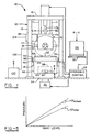
- an apparatus for automatically testing and analyzing tires is designated generally by the numeral 10.
- a pneumatic tire 11 is carried by the apparatus 10 for providing at least a foot print image and load-deflection curves of the tire 11 which are employed to analyze the performance wear characteristics thereof.
- the tire 11 is carried by a frame 12 which includes a plurality of posts 14 that are vertically oriented and supported by a ground surface.
- a pair of side bars 18 interconnect the posts 14 from front to back.
- other cross-pieces and bars may be included to structurally stabilize the frame 12.
- a processor 28 is connected to the hydraulic control system 24 and various data-gathering instruments carried by the frame 12.
- the processor 28 contains the necessary hardware, software and memory to control the operation of the apparatus 10 and to perform at least the tests performed on the tire 11 which will be discussed hereinbelow. Where appropriate, letter designations indicate the connection of the processor 28 to the appropriate component carried by the frame 12.
- a keyboard 30 is connected to the processor 28 and provides the necessary communication between an operator and the apparatus 10.
- a hydraulic lift 32 which is connected to the hydraulic control system 24, is disposed below the ground surface.
- a lift plate 34 which is connected to the hydraulic lift 32, is normally provided at the same level as the ground surface. The lift plate 34 moves the tire 11 from a ground surface position to a position where it can be loaded onto the frame 12. Of course, other means may be employed to lift the tire 11 from the ground surface into the frame 12.
- a pair of opposed slide tracks 40 extend from the side bars 18 to carry a test pod 42. It will be appreciated that the test pod 42 is moved upon the slide tracks 40 by the hydraulic control system 24 and is also connected to the processor 28 for sending test data thereto.
- the test pod 42 includes a housing 44 from which extends a pair of rails 46 that ride on the slide tracks 40. As best seen in Fig. 2, the test pod 42 is movable toward the rear of the apparatus 10 a sufficient distance to allow clearance of the lift plate 34 when the tire 11 is to be loaded onto the frame 12. Upon completion of the loading of the tire 11 onto the frame 12, the test pod 42 is moved into a position underneath the tire 11.
- a pair of housing tracks 48 are disposed at the top lateral edges of the housing 44.
- a transparent plate 50 is carried by the housing 44 and is disposed between the housing tracks 48.
- the transparent plate 50 can be made of any optically clear material, in the preferred embodiment the transparent plate 50 is made of glass.
- a cover plate 52 which is connected to a pneumatic control system (not shown), is received upon the housing tracks 48 and is movable to slide over the transparent plate 50 when desired.
- a pair of lights 54 are disposed near the lateral edges of the transparent plate 50 to provide a substantially constant illumination thereof.
- a pair of light sensors 56 are disposed near corresponding light sources 54 and are connected to a voltage regulator (not shown) to power the lights and maintain a desired illumination level.
- the light sensors 56 provide a feedback to the voltage regulator so that whenever the illumination level of the light sources 54 changes, appropriate corrective action is taken. This ensures that the foot print testing, to be described hereinbelow, is properly performed.
- the housing 44 includes a mirror 58 which is disposed underneath the transparent plate 50 and is disposed at about a 45° angle.
- the mirror 58 reflects an image of the tire 11, which is coupled to the transparent plate 50, to a camera 60 which is connected to the processor 28.
- the camera 60 is a charge coupled device which provides an array of picture elements or pixels in a 640 x 480 array.
- the camera 60 generates a gray-scale image wherein each pixel represents a corresponding area of the tire foot print.
- the processor 28 receives for each pixel, an intensity value between gray levels of 0 (darkest) and 255 (brightest). This two-dimensional array of intensity values is stored in an image data file in the processor 28.
- a frame grabber board (not shown) is connected between the camera 60 and the processor 28 so that the proper image of the tire foot print is stored.
- the mirror 58 is employed to maximize the field of view of the camera 60.
- the structure of the housing 48 can be made more compact by employing the mirror 58 to transfer an image to the camera 60.
- the camera 60 may include more than one camera to obtain the necessary field of view. For example, one camera, which has a 9" x 12" field of view, is typically used to generate an image of a regular passenger tire. Alternatively, a wide-view camera, which can capture a 16" x 20" field of view, may be employed to capture images of race tires.
- a camera mount 62 may carry either or both of the cameras 60 mentioned above. The camera mount 62 is movable in at least two axes to allow adjustment in the viewing angle of the cameras. Movement of the camera 60 facilitates finding the center of the foot print image.
- a reflective paper 64 such as a photographic backing paper, or other medium is disposed on the transparent plate 50 prior to coupling the tire 11 thereto.
- the medium 64 functions as a reflective surface which provides for the generation of internal reflection light when a force is applied to the transparent plate 50.
- the foot print of the tire 11 is apparent through the internal reflection light generated when the tire 11 is forcefully loaded upon the reflective paper 64 against the illuminated transparent plate 50.
- a video cassette recorder (not shown) may be connected to the camera 60 for storage of the foot print image for later analysis.
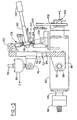
- a loading plate 70 is slidable on a pair of guide bars 71 that extend downwardly from the cross-piece 16.
- the loading plate 70 can provide a load force of up to about 22241 N (5000 pounds) and has at least a 55.88 cm (22-inch) range of motion.
- the loading plate has a front side 72 which faces the tire 11 and a rear side 74 which opposes the front side 72.
- a piston mount 76 extends from the front side 72 and interconnects the load plate 70 to a load piston 78.
- the load piston 78 is actuated by the hydraulic control system 24.
- a load cell 80 which is connected to the processor 28, is positioned on the load piston 78 to accurately provide data which indicates the amount of load applied to the tire 11.
- the loading plate 70 includes a notch 84 near the bottom thereof.
- a pair of opposed camber mounts 86 extend from the front side 72 with the notch 84 therebetween.
- a bushing 88 is provided in each of the camber mounts 86.
- a spindle housing 90 is carried by the camber mounts 86 and is received within the notch 84.
- a pair of camber pins 92 extend outwardly from the spindle housing 90 and are correspondingly received in each of the bushings 88 and pivot thereabout.
- a spindle 94 is rotatably received in the spindle housing 90.
- a tire mount 96 is located at one end of the spindle 94 and receives the tire 11.
- a chuck 98 secures the tire 11 to the tire mount 96 during testing.
- a deflection cell 99 is coupled to the loading plate 70 in a manner well known in the art to measure the amount of deflection thereof during loading.
- An encoder 100 which is connected to the processor 28, is also coupled to the spindle 94 for monitoring the rotation thereof.
- a drive assembly 102 which is connected to an electric motor 104, is mounted on the spindle housing 90 and is connected to the spindle 94 to control the rotation thereof.
- the motor 104 may be actuated by the hydraulic control system 24 or other electric power source.
- a housing mount 106 extends from the spindle housing 90 and is connected to a turnbuckle 108 which is connected at its opposite end to a plate mount 110 which extends from the rear side 74 of the loading plate 70.
- the turnbuckle 108 includes a threaded rod 112 which has a plurality of left-hand threads 114 at the end near the plate mount 110 and a plurality of right-hand threads 116 at the end of the threaded rod 112 near the housing mount 106.
- a hex member 118 is disposed between the left-hand threads 114 and the right-hand threads 116 and is connected to a ratchet 120.
- a lock nut 122 is disposed on the left-hand threads 114 while a lock nut 124 is disposed on the right-hand threads 116.
- a reversing knob 126 is disposed at the end of the ratchet 120 opposite the hex member 118.
- the lock nuts 122 and 124 are loosened and the ratchet 120 is pivoted to expand or retract the turnbuckle 108 between the plate mount 110 and the housing mount 106. Accordingly, as the ratchet 120 is pivoted or stroked, a camber is imparted on the spindle 94. This allows the tire 11 mounted to the spindle 94 to have a camber imparted thereto.
- An angle inclinometer 128 may be coupled to the motor 104, spindle housing 90 or connected attachments to determine the amount of camber imparted by the ratchet 120. These angle readings may be provided to the processor 28. Upon attaining the desired camber angle, the lock nuts 122 and 124 are tightened to hold the spindle housing 90 in place. In the preferred embodiment, the turnbuckle 108 and associated linkage can impart a range of tire camber angles of about +/-6°. It will be appreciated that different camber angles generate different tire foot prints when the tire 11 is coupled to the transparent plate 50. Moreover, these different tire foot print test patterns can provide insight into how the tire may perform during use, such as in wear.
- a pressurized air supply 130 is connected to the processor 28.
- a flexible hose 132 is connected between the pressurized air supply 130 and the tire 11 to provide a monitored air pressure to the tire.
- the tire 11 is inflated by the pressurized air supply 130 to obtain the load-deflection curves.
- the tire 11 is rolled onto the lift plate 34, whereupon the hydraulic lift 32 positions the tire 11 so that it can be easily positioned onto the tire mount 96.
- the operator then tightens the chuck 98 onto the tire mount 96 to secure the tire 11 to the spindle 94.
- the lift plate 34 is retracted to the ground surface and the test pod 42 is positioned underneath the tire 11.
- the cover plate 52 is retracted on the housing tracks 48 to expose the transparent plate 50 to the tire 11.
- the light sources 54 within the housing 44 are illuminated and the medium 64 is placed over the transparent plate 50.
- the tire 11 is inflated to a predetermined pressure by the air supply 130, whereupon the loading plate 70 is lowered to couple the tire 11 to the test pod 42.
- the camera 60 captures a gray-scale digital image of the tire foot print imparted on the medium 64. This tire foot print image is captured by the processor 28, whereupon the testing analysis is performed.
- the spindle housing 90 may be imparted with a desired camber angle as described above.
- the loading plate 70 lifts the spindle housing 90. If desired, the motor 104 engages the drive assembly 102 and rotates the spindle 94 a predetermined amount. Typically, the tire 11 is rotated in about 120° increments to obtain three tire foot prints from a single tire. Upon completion of the rotation of the tire 11, the loading plate 70 is re-coupled with the test pod 42.
- the processor 28 and the hydraulic control system 24 position the cover plate 52 over the transparent plate 50.
- the loading plate 70 is lowered and the tire 11 is coupled to the test pod 42.
- the deflection cell 99 measures the deflection of the tire 11 and transmits this data to the processor 28.
- the processor instructs the loading plate 70 to step through various increments of radial load forces and measures the corresponding deflection measurements provided by the deflection cell 99.
- the processor 28 instructs the hydraulic control system 24 to release the loading plate 70 and the tire is de-coupled from the test pod 42. At this time, the processor 28 increases the tire inflation pressure and the above deflection data is collected for that particular inflation pressure.
- the data collected from the foot print testing and the load-deflection testing can be used to provide various testing analyses.
- a foot print shape analysis can be generated to automatically analyze several geometric attributes of the tire foot print.
- the gray-scale image generated by the camera 60 is analyzed to determine the foot print contact area, the void area (non-contacting area within the foot print perimeter), foot print width and foot print length at various locations across the foot print. These parameters are used in evaluating tire performance with respect to wet and dry traction, tread wear and handling.
- the gray-scale image can also be manipulated to provide a foot print pressure mapping.
- the processor 28 converts the gray level intensity values over the foot print to contact pressure values.
- This pressure data may be converted to a colorized display "map" showing contact pressure changes as color variations in a computer-generated picture of the foot print.
- the foot print pressure mapping can then be utilized to identify locations of non-uniformities or pressure disturbances that can impact tire wear, ride or handling properties.
- the foot print pressure map can be further analyzed for pressure variations (gradients) across lugs and ribs of the tire that specifically correlate to irregular wear performance. This analysis is beneficial because of the high spatial resolution and instantaneous data collection attributes provided by the apparatus 10. This feature is advantageous over the prior art in that traditional pressure measurement methods utilized a pressure probe imbedded in the ground and required multiple tire loadings to sample numerous locations of the foot print which were ill-suited to calculate pressure gradient values.
- radial load-deflection curves can also be derived.
- cover plate 52 By employing the cover plate 52 in the testing of the tire 11, radial load-deflection curves can also be derived.
- radial load-deflection curves By employing an automated process, only two deflection-curve readings are required to forecast other load-deflection curves at other inflation pressures. This data can then be employed to determine a tire radial stiffness which is employed to evaluate tire dynamic and vibrational behavior.
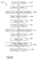
- a first step 152 requires that the tire 11 be loaded onto the apparatus 10 and in particular the spindle 94.
- the loading plate 70 couples the tire 11 to the transparent plate 50 with the medium 64 disposed therebetween, whereupon the processor 28 records the actual load value imparted thereby for designation as LOAD ACTUAL .
- the camera 60 grabs the foot print image of the tire 11 and transfers this gray-scale image to the processor 28.
- a predetermined spatial correction factor adjusts each pixel gray level value based upon pixel location with respect to the light intensity to ensure the accuracy of the pressure mapping.
- the processor 28, at step 160 assigns an arbitrary trial value for the calibration factor (CF TRIAL ) to compute pressure values from the gray level pixel values. As seen in Fig. 5, there is a corresponding relationship between the gray level values and the pressure values. In other words, the CF TRIAL value is multiplied by the gray value of each pixel to compute a pressure value at each pixel location, as designated in step 162.
- these gray level pressure values are summed over the entire foot print area to derive a LOAD TRIAL value.
- the processor 28 computes an actual calibration factor value (CF ACTUAL ) by multiplying CF TRIAL times (LOAD ACTUAL )/(LOAD TRIAL ).
- the processor 28 re-computes the pressure value at each pixel location by multiplying CF ACTUAL times the gray level value of each pixel in the foot print image. This corrected pressure data is then written to the memory within the processor 28 at step 170. The procedure eliminates the need for an independent calibration test to determine CF ACTUAL each time the reflective paper 64 is replaced on the transparent plate 50, thereby saving substantial time and costs. As seen in Figs.
- steps 160-168 generate a linear relation between pressure and gray level. Such a relation has been demonstrated for pressure ranges found in passenger and light truck tires, as well as race tires. As discussed previously, these contact pressure values associated with each pixel are employed in the foot print shape analysis, the foot print pressure mapping and the pressure gradient analysis. Upon collection of the data from a single foot print, the apparatus 10 then rotates the tire 11 to a different position on the tire to collect similar data. This data can then be stored and reviewed at a later time to assist in the design process.
- a method of obtaining load-deflection data from a tire is designated generally by the numeral 200.
- a first step 202 requires that the tire 11 be loaded onto the frame 12 in a manner described above.
- the tire 11 is then inflated by the pressurized air supply 130 to a first inflation pressure at step 204.
- the loading plate 70 couples the tire 11 to the cover plate 52 at predetermined load increments.
- the processor 28 records deflection values from the deflection cell 99 that are associated with the predetermined load increments.
- the processor 28 releases the loading plate 70.
- the processor 28 instructs the pressurized air supply 130 to increase the pressure within the tire to a second inflation pressure.
- the loading plate 70 re-couples the tire 11 to the cover plate 52 at predetermined increments and, at step 216, the processor records the corresponding deflection values.
- the load is released and the tire is dismounted from the apparatus 10.
- the processor 28 computes coefficient values which are employed to determine load-deflection curves at other inflation pressures. Those skilled in the art will appreciate that steps 206 and 208 and steps 212 and 214 collect between 100 to 200 equally spaced measures of load and deflection values over the test.
- the coefficients C 1 , C 2 and C 3 are coeffcients determined by a computer regression analysis implemented by the processor 28. Once the coefficients are determined, load-deflection curves at other inflation pressures can be extrapolated from the above equation, as shown at step [232]. By employing the above equation, time is saved and testing costs are reduced.
- the first inflation pressure is the minimal value desired from the load-deflection curves and the second inflation pressure is the highest value desired of the load-deflection curves. This ensures the accuracy of the extrapolated load-deflection curves.
- test data can be employed to quickly determine whether a design change is beneficial or detrimental to the performance of a tire. This reduces time spent on the tire design phase and allows bringing a tire to market much quicker than had been previously known.
Landscapes
- Physics & Mathematics (AREA)
- General Physics & Mathematics (AREA)
- Tires In General (AREA)
- Length Measuring Devices By Optical Means (AREA)
- Force Measurement Appropriate To Specific Purposes (AREA)
Claims (13)
- Vorrichtung zum Prüfen von Reifen (10), umfassend:ein Gestell (12),eine Belastungsplatte (70), die innerhalb des Gestells (12) befestigt ist;eine Reifenwelle (94), die sich von der Belastungsplatte (70) erstreckt, wobei die Reifenwelle (94), einen zu prüfenden Reifen aufnehmen kann,eine Prüfgondel oder -gehäuse (42), und ein Prozessor (28) zum Steuern des Betriebs der Belastungsplatte (70) um den Reifen mit der Prüfgondel (42) in Verbindung zu bringen, wobei der Prozessor (28) mit der Prüfgondel (42) verbunden ist, wobei der Prozessor und die Prüfgondel ausgelegt sind, entweder ein.digitales Bild des Reifenlaufflächenabdrucks oder einer Vielzahl von Lastbiegungskurven des Reifens zu erzeugen.
- Vorrichtung nach Anspruch 1, bei der die Testgondel (42) folgendes umfaßt:ein Gehäuse (44), das vom Gestell (12) getragen wird,eine transparente Platte (50), die vom Gehäuse (44) getragen wird, undeine Abdeckplatte (52), die vom Gehäuse (44) getragen wird, wobei eine der transparenten Platten (50) und die Abdeckplatte (52) mit dem Reifen (11) verbunden ist, während der Prozessor (28) den Reifenabdruck oder die Kurven erzeugt.
- Vorrichtung nach Anspruch 2, bei der die Abdeckplatte (52) verschiebbar über der transparenten Platte (58) beweglich ist.
- Vorrichtung nach Anspruch 1, bei der die Prüfgondel (42) ferner folgendes umfaßt:einen Spiegel (58), der vom Gehäuse (44) getragen wird, und winkelmässig unterhalb der transparenten Platte (50) positionierbar ist, undmindestens eine Kamera (60), die mit dem Prozessor (28) verbunden ist, und so positionierbar ist, daß ein vom Spiegel (58) reflektiertes Bild aufgefangen wird, wenn der Reifen (11) mit der transparenten Platte (50) in Verbindung steht.
- Vorrichtung nach Anspruch 3, ferner umfassend:eine Kraftmeßdose (80), die mit der Belastungsplatte (70) gekoppelt und mit dem Prozessor (28) verbunden ist,undeinen unter Druck stehender Luftvorrat (130), der mit dem Reifen (11) gekoppelt und mit dem Prozessor (28) verbunden ist, um die Menge der Biegung der Kraftmeßdose (80) und den Aufblasdruck der unter Druck stehenden Luftzufuhr zu überwachen, wenn der Reifen mit der Abdeckplatte (52) verbunden ist, um eine Vielzahl von Lastbiegungskurven zu erzeugen.
- Verfahren zum Erzeugen eines Reifenlaufflächenabdrucks, umfassend folgende Stufen:Vorsehen eines Gestells (12), das eine Belastungsplatte (70) aufnimmt, von der sich eine Reifenwelle (94) erstreckt, die einen Reifen (11) aufnimmt,Befestigen des Reifens (11) auf einer Welle (94),in Verbindung bringen des Reifens mit einer transparenten Platte (50) bei einem vorbestimmten Belastungsniveau, Aufnehmen eines graustufigen Bildes des Reifens mit einer Kamera (60),.die unterhalb der transparenten Platte (50) positioniert ist, wobei das graustufige Bild eine Anordnung von Pixeln umfaßt, in dem jedes Pixel in der Pixelanordnung einem Grauniveauwert zugeordnet ist,Festsetzen eines Prüfungskalibrierungsfaktors, computermäßiges Berechnen eines Prüfungsbelastungswertes mit dem vorbestimmten Belastungsniveau, den Grauniveauwerten, dem Prüfungskalibrierungsfaktor, computermäßiges Errechnen eines tatsächlichen Kalibrierungsfaktors mit dem Prüfungskalibrierungsfaktor, dem vorbestimmten Belastungsniveau und dem Prüfungsbelastungsniveau,computermäßiges Errechnen eines korrigierten Pixeldruckwertes für jedes Pixel mit dem tatsächlichen Kalibrierungsfaktor, undErzeugen eines Laufflächenabdrucks des Reifens.
- Verfahren nach Anspruch 6, ferner umfassend folgende Stufen:Herleiten und Speichern einer ersten Laufflächenabdrucksanalyse mit den korrigierten Pixeldruckwerten,Entkoppeln des Reifens (11) von der transparenten Platte (50),Drehen des Reifens in einem vorbestimmten Ausmaß, Entkoppeln des Reifens von der transparenten Platte (50) und computermäßiges Berechnen eines neuen, korrigierten Pixeldruckwertes, um eine zweite Laufflächenabdrucksanalyse zum Vergleich mit der ersten Laufflächenabdrucksanalyse zu erzeugen.
- Verfahren nach Anspruch 6, ferner umfassend folgende Stufen:Ableiten und Speichern einer ersten Laufflächenabdruckdarstellung mit den korrigierten Pixelwerten,Lösen des Reifens (11) von der transparenten Platte (50), Drehen des Reifens in einem vorbestimmten Ausmaß,Lösen des Reifens von der transparenten Platte (50) und Wiederberechnung eines neuen, korrigierten Pixeldruckwertes, um eine zweite Laufflächenabdruck-Druckdarstellung zum Vergleich mit der ersten Laufflächenabdruck-Druckdarstellung zu erzeugen.
- Verfahren nach Anspruch 6, ferner umfassend folgende Stufe:Ableiten und Speichern einer Laufflächenabdruck-Druckdarstellung aus dem korrigierten Pixelwert.
- Verfahren nach Anspruch 6, ferner umfassend die folgende Stufe:Ableiten und Speichern einer Druckgradientenanalyse aus den korrigierten Pixelwerten.Ableiten und Speichern einer Druckgradientenanalyse aus den korrigierten Pixelwerten.
- Verfahren zum Erzeugen einer Vielzahl von Lastbiegungskurven, umfassend folgende Stufen:Vorsehen eines Gestells (12), das eine Belastungsplatte (70) aufnimmt, von der sich eine Reifenwelle (94) erstreckt, die einen Reifen aufnimmt,Befestigen des Reifens (11) auf einer Welle (94),Aufblasen des Reifens auf einen ersten, vorbestimmten Aufblasdruckwert,Durchbiegen des Reifens auf einer Abdeckplatte (52) bis zu einem vorbestimmten Belastungsniveau,Entladen des Reifens (11) von der Abdeckplatte (52), Aufblasen des Reifens auf einen zweiten, vorbestimmten Aufblasdruckwert,Durchbiegen des Reifens auf der Abdeckplatte (52) bei einem weiteren vorbestimmten Belastungsniveau,Messen einer zweiten Biegungs/Belastungskurve des Reifens, undExtrapolieren der Durchbiegungsausmaße des Reifens bei anderen Aufblasdruckwerten von den ersten und zweiten Biegungs/Belastungskurven.
- Verfahren nach Anspruch 11, bei dem andere Aufblasdruckwerte zwischen dem ersten und zweiten Aufblasdruckwert liegen.
- Verfahren nach Anspruch 11, bei dem Reifensteifheitswerte auf den extra polierten Biegungs/Belastungskurven abgeleitet werden.
Applications Claiming Priority (2)
| Application Number | Priority Date | Filing Date | Title |
|---|---|---|---|
| US08/729,358 US5777219A (en) | 1996-10-16 | 1996-10-16 | Apparatus and related methods for automatically testing and analyzing tires utilizing a test pod with a slidably movable cover plate and a gray scale normalization technique |
| US729358 | 1996-10-16 |
Publications (3)
| Publication Number | Publication Date |
|---|---|
| EP0837308A2 EP0837308A2 (de) | 1998-04-22 |
| EP0837308A3 EP0837308A3 (de) | 1999-03-10 |
| EP0837308B1 true EP0837308B1 (de) | 2003-06-18 |
Family
ID=24930682
Family Applications (1)
| Application Number | Title | Priority Date | Filing Date |
|---|---|---|---|
| EP97117742A Expired - Lifetime EP0837308B1 (de) | 1996-10-16 | 1997-10-14 | Vorrichtung und zugehörige Verfahren zum automatischen Prüfen und Analysieren von Reifen |
Country Status (6)
| Country | Link |
|---|---|
| US (1) | US5777219A (de) |
| EP (1) | EP0837308B1 (de) |
| JP (1) | JP3959162B2 (de) |
| CA (1) | CA2218352A1 (de) |
| DE (1) | DE69722887T2 (de) |
| ES (1) | ES2196230T3 (de) |
Families Citing this family (31)
| Publication number | Priority date | Publication date | Assignee | Title |
|---|---|---|---|---|
| US6134957A (en) * | 1997-07-16 | 2000-10-24 | Ford Global Technologies, Inc. | Multiple degree-of-freedom tire modeling method and system for use with a vehicle spindle-coupled simulator |
| DE19731486C2 (de) * | 1997-07-22 | 2001-02-22 | Beissbarth Gmbh | Reifenprüfvorrichtung |
| US6178814B1 (en) | 1997-08-22 | 2001-01-30 | John Michael Curtis | Portable motorized tire support |
| US6089083A (en) * | 1997-08-22 | 2000-07-18 | Curtis; John Michael | Tire inspection and preparation device |
| US6083268A (en) * | 1998-04-27 | 2000-07-04 | Bridgestone/Firestone, Inc. | Method for designing pneumatic tires for rolling conditions |
| EP1043578B1 (de) * | 1999-04-09 | 2004-10-13 | Steinbichler Optotechnik Gmbh | Optisches Prüfgerät für Reifen |
| JP4363506B2 (ja) * | 2000-08-10 | 2009-11-11 | 横浜ゴム株式会社 | 空気入りタイヤのトレッド摩耗量測定方法 |
| KR20020092527A (ko) * | 2001-06-04 | 2002-12-12 | 한국타이어 주식회사 | 타이어의 접지압 분포 측정장치 |
| ES2222776B1 (es) * | 2002-02-25 | 2006-01-16 | Universidad De Malaga | Sistema medidor de la distribucion de presiones normales y de la geometria del contacto en la huella de contacto de neumaticos con su pista de rodadura. |
| US6763706B1 (en) * | 2003-02-12 | 2004-07-20 | Akron Special Machinery, Inc. | Load cell conicity calibration apparatus and method |
| US6990859B2 (en) * | 2004-04-05 | 2006-01-31 | Bridgestone Firestone North American Tire, Llc | Locking mechanism for load analyzer |
| BRPI0512131A (pt) * | 2004-06-17 | 2008-02-06 | Mts System Corp | método de obter arquivos de ativação para uma máquina de teste para testar aros de roda e máquina de teste para teste de aros de roda |
| US7197920B2 (en) * | 2005-04-05 | 2007-04-03 | Ford Global Technologies, Llc | Test apparatus for accelerated wheel and suspension component structural durability |
| CN100442008C (zh) * | 2005-08-08 | 2008-12-10 | 旭东机械(昆山)有限公司 | 轮胎检测装置 |
| DE102009036145A1 (de) * | 2008-08-05 | 2010-04-29 | Link Engineering Company, Plymouth | Biaxiale Rad-Testanordnung |
| DE102009006705B4 (de) * | 2009-01-29 | 2022-06-30 | Bayerische Motoren Werke Aktiengesellschaft | Verfahren zum Erkennen der Abnutzung an einer Lauffläche von mindestens einem Reifen eines Fahrzeugs |
| WO2011065938A1 (en) * | 2009-11-24 | 2011-06-03 | Michelin Recherche Et Technique, S.A. | On vehicle testing of tire resistance to sidewall aggression |
| WO2011065943A1 (en) * | 2009-11-25 | 2011-06-03 | Michelin Recherche Et Technique, S.A. | Apparatus and method for evaluating tire self-cleaning capability |
| US8705803B2 (en) * | 2009-11-25 | 2014-04-22 | Compagnie Generale Des Etablissements Michelin | Method for evaluating tire self-cleaning capability by analyzing recorded images |
| CN101886983A (zh) * | 2010-06-10 | 2010-11-17 | 沈阳理工大学 | 一种轮胎运动特性仿真系统 |
| US8955374B2 (en) * | 2011-11-08 | 2015-02-17 | Bridgestone Americas Tire Operations, Llc | Footprint test apparatus and method of use |
| CN103454095A (zh) * | 2012-05-29 | 2013-12-18 | 安进轮胎再生资源(上海)有限公司 | 轮胎充气检验机 |
| DE102013107018A1 (de) | 2013-07-04 | 2015-01-08 | Karlsruher Institut für Technologie | Vorrichtung zur Erfassung einer Auflagefläche |
| JP6386304B2 (ja) * | 2014-08-29 | 2018-09-05 | 東洋ゴム工業株式会社 | タイヤ踏面の接地面挙動測定装置、及びタイヤ踏面の接地面挙動測定方法 |
| JP6422162B2 (ja) * | 2015-03-19 | 2018-11-14 | 住友ゴム工業株式会社 | タイヤの剛性感評価方法 |
| JP6637673B2 (ja) * | 2015-04-28 | 2020-01-29 | キヤノン株式会社 | 当接状態確認方法、弾性部材の評価装置、および表面改質した弾性部材の判別方法 |
| EP3519792B1 (de) * | 2016-09-30 | 2024-11-06 | Pirelli Tyre S.p.A. | Verfahren und system zur detektion einer druckverteilung in einem aufstandsflächenbereich eines reifens |
| CN108519242B (zh) * | 2018-04-27 | 2019-11-19 | 安徽工程大学 | 一种汽车轮胎检测平台 |
| IT201800010155A1 (it) | 2018-11-08 | 2020-05-08 | Bridgestone Europe Nv Sa | Unita' e metodo di prova per acquisire otticamente una impronta a terra o una caratteristica analoga di uno pneumatico |
| CN109946002B (zh) * | 2019-02-27 | 2021-02-12 | 江苏大学 | 一种轮胎接地压力的非接触测量台架 |
| CN110095345B (zh) * | 2019-04-12 | 2020-03-06 | 山东科技大学 | 一种加载刚度可调的真三轴试验机及试验方法 |
Family Cites Families (14)
| Publication number | Priority date | Publication date | Assignee | Title |
|---|---|---|---|---|
| US4233838A (en) * | 1979-05-22 | 1980-11-18 | Uniroyal, Inc. | Load control for tire test machine |
| US4434652A (en) * | 1982-01-18 | 1984-03-06 | The Goodyear Tire & Rubber Company | Automated tire measurement techniques |
| JPH081377B2 (ja) * | 1984-12-28 | 1996-01-10 | 株式会社東芝 | タイヤ負荷試験断層撮影装置 |
| JPH0363506A (ja) * | 1989-08-01 | 1991-03-19 | Ohtsu Tire & Rubber Co Ltd :The | タイヤ形状撮影方法及び装置 |
| JPH0749938B2 (ja) * | 1989-11-02 | 1995-05-31 | 住友ゴム工業株式会社 | タイヤ接地面観測装置及び観測方法 |
| JPH0756464B2 (ja) * | 1990-02-01 | 1995-06-14 | 住友ゴム工業株式会社 | タイヤ接地形状・接地圧測定装置 |
| JPH04197802A (ja) * | 1990-11-29 | 1992-07-17 | Sumitomo Rubber Ind Ltd | 二重構造ラジアルタイヤ |
| US5347588A (en) * | 1991-10-11 | 1994-09-13 | Bridgestone | Method and apparatus for video imaging of tire ground contact patch |
| US5245867A (en) * | 1991-12-16 | 1993-09-21 | Bridgestone Corporation | Method and apparatus for measuring tire parameters |
| US5249460A (en) * | 1991-12-16 | 1993-10-05 | Bridgestone Corporation | Method and apparatus for measuring irregular tread wear |
| US5357799A (en) * | 1992-07-14 | 1994-10-25 | Bridgestone Corporation | Method and apparatus for determining abrasion potential of tire treads |
| US5313827A (en) * | 1992-09-28 | 1994-05-24 | The Goodyear Tire & Rubber Company | Method and apparatus for detecting ply defects in pneumatic tires |
| US5481907A (en) * | 1993-12-13 | 1996-01-09 | Mts Systems Corporation | Tire testing system having focused links reducing cosine errors |
| JP2829249B2 (ja) * | 1994-11-01 | 1998-11-25 | 住友ゴム工業株式会社 | 台上摩耗エネルギー測定試験機 |
-
1996
- 1996-10-16 US US08/729,358 patent/US5777219A/en not_active Expired - Lifetime
-
1997
- 1997-10-14 DE DE69722887T patent/DE69722887T2/de not_active Expired - Lifetime
- 1997-10-14 EP EP97117742A patent/EP0837308B1/de not_active Expired - Lifetime
- 1997-10-14 ES ES97117742T patent/ES2196230T3/es not_active Expired - Lifetime
- 1997-10-15 JP JP29646697A patent/JP3959162B2/ja not_active Expired - Fee Related
- 1997-10-15 CA CA002218352A patent/CA2218352A1/en not_active Abandoned
Also Published As
| Publication number | Publication date |
|---|---|
| DE69722887T2 (de) | 2003-12-04 |
| JP3959162B2 (ja) | 2007-08-15 |
| US5777219A (en) | 1998-07-07 |
| CA2218352A1 (en) | 1998-04-16 |
| ES2196230T3 (es) | 2003-12-16 |
| DE69722887D1 (de) | 2003-07-24 |
| JPH10185767A (ja) | 1998-07-14 |
| EP0837308A3 (de) | 1999-03-10 |
| EP0837308A2 (de) | 1998-04-22 |
Similar Documents
| Publication | Publication Date | Title |
|---|---|---|
| EP0837308B1 (de) | Vorrichtung und zugehörige Verfahren zum automatischen Prüfen und Analysieren von Reifen | |
| US6069966A (en) | Apparatus and method for tire condition assessment | |
| US6199424B1 (en) | Portable universal friction testing machine and method | |
| US6883962B2 (en) | Tire wear forecasting method and apparatus | |
| US5092166A (en) | Apparatus for determining shape of contact patch and contact pressure of tires | |
| EP0671621B1 (de) | Tragbare Prüfmaschine für die Gleichförmigkeit eines Reifens | |
| US6546791B2 (en) | Indoor hydroplaning test apparatus and method | |
| US6349587B1 (en) | Portable universal friction testing machine and method | |
| US7614275B2 (en) | Method and apparatus for determining coefficient of friction | |
| Sakai | Measurement and visualization of the contact pressure distribution of rubber disks and tires | |
| CN109269928B (zh) | 一种轮胎磨耗试验机及其检测方法 | |
| CA2553906C (en) | Apparatus and related methods for automatically testing and analyzing tires | |
| US6032522A (en) | Apparatus and method for inspecting inflation of and supported weight on vehicle tires | |
| JPH0763658A (ja) | タイヤ踏面の接地部測定装置 | |
| US3478581A (en) | Apparatus for measuring tire uniformity | |
| JPH05172664A (ja) | すべり摩擦力測定装置 | |
| Roth et al. | Geometric and normal contact stress analysis of a rolling tire footprint | |
| JP2008083015A (ja) | 車両流れ量の管理方法,推定方法およびシステム | |
| JP2005132156A (ja) | タイヤ接地形状観測方法及びその装置 | |
| KR100302061B1 (ko) | 타이어 사이드월 부위의 풋 프린트 형상 측정법 및 그 장치 | |
| CN120628998A (zh) | 一种沥青混合料推平质量检测设备 | |
| RU230068U1 (ru) | Устройство для определения площади пятна контакта шин тракторов и сельскохозяйственных машин | |
| CN214173264U (zh) | 自行车叉骨偏向检测装置 | |
| KR20050017508A (ko) | 하중상태의 타이어 프로파일 측정장치 | |
| JPS647300Y2 (de) |
Legal Events
| Date | Code | Title | Description |
|---|---|---|---|
| PUAI | Public reference made under article 153(3) epc to a published international application that has entered the european phase |
Free format text: ORIGINAL CODE: 0009012 |
|
| AK | Designated contracting states |
Kind code of ref document: A2 Designated state(s): DE ES FR GB IT |
|
| AX | Request for extension of the european patent |
Free format text: AL;LT;LV;RO;SI |
|
| PUAL | Search report despatched |
Free format text: ORIGINAL CODE: 0009013 |
|
| AK | Designated contracting states |
Kind code of ref document: A3 Designated state(s): AT BE CH DE DK ES FI FR GB GR IE IT LI LU MC NL PT SE |
|
| AX | Request for extension of the european patent |
Free format text: AL;LT;LV;RO;SI |
|
| 17P | Request for examination filed |
Effective date: 19990219 |
|
| AKX | Designation fees paid | ||
| RBV | Designated contracting states (corrected) |
Designated state(s): DE ES FR GB IT |
|
| RAP1 | Party data changed (applicant data changed or rights of an application transferred) |
Owner name: BRIDGESTONE/FIRESTONE NORTH AMERICA TIRE LLC |
|
| 17Q | First examination report despatched |
Effective date: 20020809 |
|
| GRAH | Despatch of communication of intention to grant a patent |
Free format text: ORIGINAL CODE: EPIDOS IGRA |
|
| GRAH | Despatch of communication of intention to grant a patent |
Free format text: ORIGINAL CODE: EPIDOS IGRA |
|
| GRAA | (expected) grant |
Free format text: ORIGINAL CODE: 0009210 |
|
| AK | Designated contracting states |
Designated state(s): DE ES FR GB IT |
|
| REG | Reference to a national code |
Ref country code: GB Ref legal event code: FG4D |
|
| REF | Corresponds to: |
Ref document number: 69722887 Country of ref document: DE Date of ref document: 20030724 Kind code of ref document: P |
|
| REG | Reference to a national code |
Ref country code: ES Ref legal event code: FG2A Ref document number: 2196230 Country of ref document: ES Kind code of ref document: T3 |
|
| ET | Fr: translation filed | ||
| PLBE | No opposition filed within time limit |
Free format text: ORIGINAL CODE: 0009261 |
|
| STAA | Information on the status of an ep patent application or granted ep patent |
Free format text: STATUS: NO OPPOSITION FILED WITHIN TIME LIMIT |
|
| 26N | No opposition filed |
Effective date: 20040319 |
|
| PGFP | Annual fee paid to national office [announced via postgrant information from national office to epo] |
Ref country code: GB Payment date: 20050914 Year of fee payment: 9 |
|
| PGFP | Annual fee paid to national office [announced via postgrant information from national office to epo] |
Ref country code: ES Payment date: 20051020 Year of fee payment: 9 |
|
| GBPC | Gb: european patent ceased through non-payment of renewal fee |
Effective date: 20061014 |
|
| PG25 | Lapsed in a contracting state [announced via postgrant information from national office to epo] |
Ref country code: GB Free format text: LAPSE BECAUSE OF NON-PAYMENT OF DUE FEES Effective date: 20061014 |
|
| REG | Reference to a national code |
Ref country code: ES Ref legal event code: FD2A Effective date: 20061016 |
|
| PG25 | Lapsed in a contracting state [announced via postgrant information from national office to epo] |
Ref country code: ES Free format text: LAPSE BECAUSE OF NON-PAYMENT OF DUE FEES Effective date: 20061016 |
|
| PGFP | Annual fee paid to national office [announced via postgrant information from national office to epo] |
Ref country code: FR Payment date: 20101004 Year of fee payment: 14 |
|
| PGFP | Annual fee paid to national office [announced via postgrant information from national office to epo] |
Ref country code: DE Payment date: 20101029 Year of fee payment: 14 |
|
| PGFP | Annual fee paid to national office [announced via postgrant information from national office to epo] |
Ref country code: IT Payment date: 20101016 Year of fee payment: 14 |
|
| REG | Reference to a national code |
Ref country code: FR Ref legal event code: ST Effective date: 20120629 |
|
| PG25 | Lapsed in a contracting state [announced via postgrant information from national office to epo] |
Ref country code: DE Free format text: LAPSE BECAUSE OF NON-PAYMENT OF DUE FEES Effective date: 20120501 |
|
| REG | Reference to a national code |
Ref country code: DE Ref legal event code: R119 Ref document number: 69722887 Country of ref document: DE Effective date: 20120501 |
|
| PG25 | Lapsed in a contracting state [announced via postgrant information from national office to epo] |
Ref country code: IT Free format text: LAPSE BECAUSE OF NON-PAYMENT OF DUE FEES Effective date: 20111014 Ref country code: FR Free format text: LAPSE BECAUSE OF NON-PAYMENT OF DUE FEES Effective date: 20111102 |