EP3028029B1 - Reifen prüfvorrichtung - Google Patents
Reifen prüfvorrichtung Download PDFInfo
- Publication number
- EP3028029B1 EP3028029B1 EP14753179.2A EP14753179A EP3028029B1 EP 3028029 B1 EP3028029 B1 EP 3028029B1 EP 14753179 A EP14753179 A EP 14753179A EP 3028029 B1 EP3028029 B1 EP 3028029B1
- Authority
- EP
- European Patent Office
- Prior art keywords
- tire
- rotating element
- parameter
- wheel assembly
- contact patch
- Prior art date
- Legal status (The legal status is an assumption and is not a legal conclusion. Google has not performed a legal analysis and makes no representation as to the accuracy of the status listed.)
- Active
Links
- 238000012360 testing method Methods 0.000 title claims description 57
- 239000000463 material Substances 0.000 claims description 17
- 238000000034 method Methods 0.000 claims description 16
- 238000009877 rendering Methods 0.000 claims description 2
- 239000000843 powder Substances 0.000 description 15
- 238000012545 processing Methods 0.000 description 9
- 238000004364 calculation method Methods 0.000 description 4
- 238000005096 rolling process Methods 0.000 description 4
- VYPSYNLAJGMNEJ-UHFFFAOYSA-N Silicium dioxide Chemical compound O=[Si]=O VYPSYNLAJGMNEJ-UHFFFAOYSA-N 0.000 description 3
- 238000010586 diagram Methods 0.000 description 3
- 230000006870 function Effects 0.000 description 3
- 230000001276 controlling effect Effects 0.000 description 2
- 239000000428 dust Substances 0.000 description 2
- 238000012544 monitoring process Methods 0.000 description 2
- 239000002245 particle Substances 0.000 description 2
- 239000013618 particulate matter Substances 0.000 description 2
- 230000001133 acceleration Effects 0.000 description 1
- 239000012530 fluid Substances 0.000 description 1
- 238000009533 lab test Methods 0.000 description 1
- 238000005259 measurement Methods 0.000 description 1
- 230000002093 peripheral effect Effects 0.000 description 1
- 230000002250 progressing effect Effects 0.000 description 1
- 230000001105 regulatory effect Effects 0.000 description 1
- 239000004576 sand Substances 0.000 description 1
- 230000008054 signal transmission Effects 0.000 description 1
- 239000000377 silicon dioxide Substances 0.000 description 1
- 239000000126 substance Substances 0.000 description 1
- 239000000454 talc Substances 0.000 description 1
- 229910052623 talc Inorganic materials 0.000 description 1
Images


Classifications
-
- G—PHYSICS
- G01—MEASURING; TESTING
- G01M—TESTING STATIC OR DYNAMIC BALANCE OF MACHINES OR STRUCTURES; TESTING OF STRUCTURES OR APPARATUS, NOT OTHERWISE PROVIDED FOR
- G01M17/00—Testing of vehicles
- G01M17/007—Wheeled or endless-tracked vehicles
- G01M17/02—Tyres
- G01M17/022—Tyres the tyre co-operating with rotatable rolls
Definitions
- Laboratory tire test machines are known and are used to conduct tire tread wear tests on tires such as rubber treaded pneumatic or non-pneumatic tires.
- a tire and wheel assembly is mounted to a spindle where the tire contacts and rolls against a rotating element such as a drum or the like.
- the rotating element can have a texture to simulate desired road surfaces.
- powder e.g. talc, silica sand
- the powder or other particulate matter performs two functions during testing. One function is to provide some control of the friction between the artificial test surface on the rotating element and the tire. The second function is to apply dust to the rubber tread wear particles so they do not stick to the tire or rolling element test surface.
- the tread wear particles can then be removed by a dust collection system.
- Various powders and particulates are used. Many are proprietary to the test researchers. Tread wear on the tire is also affected by changes to the test surface as testing progresses. It is often desirable to maintain a surface friction within some range for proper testing. Delivering the proper amount of powder and particulates to the tire contact patch to obtain the desired results is necessary.
- tire tread wear testing is performed on a curved surface or roller.
- the curved surface introduces geometry differences in the tire contact patch between testing on the laboratory test machine and real world use of the tire where the contact patch is substantially flat. Adjustments are typically needed to compensate for the test conditions.
- Intelligent tires is a term to indicate that the tires have instrumentation or sensor(s) applied to or embedded in the tire to provide feedback to a monitoring system in a vehicle.
- Work on “intelligent tires” is progressing at tire companies and universities in order that data from the tire is provided to the vehicle monitoring system indicative of roadway friction, tire contact patch size and tire forces. This information can be used during vehicle operation in order to improve vehicle handling and/or stability.
- the sensor(s) is installed on/in the tire structure or the tire rim to measure, typically, a mechanical change in the tire structure.
- An algorithm embodied in a computer readable medium that is executed on a processor either within the tire and wheel assembly or outside of the tire and wheel assembly interprets the signal(s) received from the sensor(s). For instance, one method employed by tire companies and universities is to install one or more accelerometers on the inside surface of the tire carcass body or innerliner near the center plane of the tire. The acceleration signal(s) typically is evaluated by the processor executing the algorithm to determine contact patch surface length and characteristics that are indicative of friction between the tire and roadway. It should be noted aspects of the invention described herein do not pertain to algorithms used to evaluate tire friction, but a merely mentioned herein as background information.
- the patent document WO 2012/091719 A1 discloses a system where a sensor embedded in a tire is used within a system for determining the tire load.
- the patent document US 2010/0031740 A1 discloses a test bench for testing a wheel-and-tire assembly including a drum on which the tire to be tested rolls.
- the present invention consists of a tire testing machine as defined in claim 1.
- a tire testing machine having a rotating element, a tire and wheel assembly having a sensor for measuring a parameter related to the tire and wheel assembly as it rotates on the rotating element and providing an output signal indicative thereof, a holder supporting the tire and wheel assembly for rotation against a surface of the rotating element, a processor configured to receive an input at least based on the output signal from the sensor, the processor configured to provide an output signal indicative of a parameter of a contact patch between a tire of the tire and wheel assembly and the rotating element, and a controlled element configured to vary a parameter related to the contact patch.
- the parameter may be a length of the contact patch.
- a tire testing machine in another aspect, includes a rotating element, a tire and wheel assembly having a sensor for measuring a parameter related to the tire and wheel assembly as it rotates on the rotating element and providing an output signal indicative thereof, a holder supporting the tire and wheel assembly for rotation against a surface of the rotating element, a processor configured to receive an input at least based on the output signal from the sensor, the processor configured to provide an output signal indicative of a parameter of friction between a tire of the tire and wheel assembly and the rolling element, and a controlled element configured to vary a parameter related to the friction.
- the controlled element may be, for example, a material supply system to adjust delivery of material to the tire and the rolling element based on an output signal from the processor.
- a method of operating a tire testing machine includes measuring a parameter using a sensor of a tire and wheel assembly of the tire testing machine, providing an output signal based on the measured parameter, receiving an input based on the output signal, generating an output signal indicative of a parameter of a contact patch between a tire of the tire and wheel assembly and a surface of a rotating element of the tire testing machine, and varying the parameter related to the contact patch.
- Generating an output signal may include, for example, estimating friction at the contact patch.
- Varying the parameter may include, for example, one or more of adjusting a position of the tire and wheel assembly relative to the rotating element, estimating friction at the contact patch, and wherein varying the parameter comprises adjusting a pressure of gas in the tire of the tire and wheel assembly, or varying the parameter comprises adjusting delivery of material to an area of the contact patch.
- the parameter may be rendered to a user.
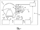
- a tire tread wear test machine is illustrated at 10 in Fig. 1 .
- the test machine 10 includes a rotating element 12 upon which a tire 14 rotates thereon.
- the rotating element 12 can take numerous forms including a large drum or wheel as illustrated or a flat belt assembly having a rotating endless belt, such as disclosed in US Patent 6,584,835 .
- Such systems are available from MTS Systems Corporation of Eden Prairie, Minnesota, USA.
- the rotating element 12 is driven by a drive motor schematically illustrated at 16 and comprising a hydraulic, pneumatic or electric motor.
- the tire 14 is mounted to a suitable wheel 15 (tire and wheel assembly 17) that in turn is mounted to a spindle (i.e. holder) of a wheel positioner, schematically illustrated at 19, which positions the tire 14 upon the rotating element 12.
- the positioner 19 can include various actuators (typically hydraulic, but could also be electric), levers, struts, pivots and the like to adjust the position of the tire and wheel assembly 17 as well as to load (apply a force) the tire 14 upon the rotating element 12. For instance, positioning can include simulated steering position or movement of the tire and wheel assembly 17 about a steering axis 18.
- a material supply system 27 that provides a powder, fluid or other substance to the rotating element 12, the tire 14 and/or otherwise is positioned so as to provide material to the tire contact patch 24.
- the material is provided through a nozzle 28 coupled to a material feeder 29 (hereinafter exemplified as providing powder).
- Material supply systems 27 are well known in the art.
- the receiver 50 is electrically connected to and provides an input signal to a friction estimation processor 60.
- the friction estimation processor 60 provides an estimated value or parameter indicative of friction at the contact patch 24, or another parameter of the tire 14 engaging the rotating element 12.
- the friction estimation processor 60 provides an output signal 64 that forms a command signal to a powder delivery controller 70.
- the powder delivery controller 70 in turn provides a control signal to the powder feeder 29.
- the sensor(s) 40 in the tire 14, along with the friction estimation processor 60 (and any or all of the foregoing hardware to provide an input to the friction estimating processor 60 based on the output signal from the sensor(s) 40) provides a feedback signal to powder delivery controller 70 that adjusts the feed rate of the powder to the tire contact patch 24.
- friction estimation processor 60 need only provide an output signal 64 that can be used to control the application of powder by the powder feeder 29.
- the friction at the tire contact patch 24 ascertained by friction estimation processor 60 can be used to ascertain when a surface (or elements forming the surface) needs to be replaced as indicated by an output signal 67.
- the test machine 10 can measure a length of the tire contact patch 24.
- one or more parameters of the test machine 10 such as any one or more of the parameters of the positioner 19 can be adjusted in order to obtain a desired length of the tire contact patch 24.
- a value indicative of the length of the tire contact patch 24 is outputted from the tire contact patch length calculation processor 90 as signal 91 and provided to a tire contact patch length regulator 120.
- the calculated value of the length of the tire contact patch 24 as calculated by the tire contact patch length calculation processor 90 can be rendered to a user though a suitable rendering device such as a monitor or a printer. The user can then adjust the gas pressure of the tire and wheel assembly 17 manually using a manually operated control valve with or without the rotary union 127.
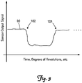
- three axis accelerometers may be employed. Multiple accelerometers may be placed across the width of the tire carcass. Multiple sensors could be installed around the circumference of the tire to increase the rate that tire information is provided from the tire. A single sensor provides information once per tire revolution whereas 2 sensor provide information twice per revolution and so on.
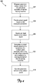
- Figure 5 is a flow chart diagram of another method 500 of operating a tire testing machine.
- Method 500 comprises, in one embodiment, receiving a signal indicative of a parameter of the tire testing machine from an intelligent tire of the tire testing machine in block 502, feeding the signal to a parameter varying system in block 504, and adjusting the parameter based on the feedback signal in block 506.
- processing modules, controllers and regulators indicated above can be implemented with analog and/or digital circuitry. It should also be noted that although separate processing modules, controllers and regulators have been illustrated, this should not be considered limiting wherein this was done in order to provide more clarity for understanding aspects of the invention. Practical embodiments of the tire testing machine 10 may include a single or multiple analog and/or digital circuits to perform one or more of the foregoing processing steps or implement one or more of the controllers, processors and regulators. In addition, it should be understood that the processing steps, or portions thereof, can be performed with hardware and/or software in any combination or portion thereof. The software comprises instructions executed by any suitable processor.
- the processor can be implemented with an electrical circuit having, for instance, a microprocessor and support peripherals such as random access memory (RAM), read only memory (ROM) and/or other computer readable, non-transitory storage mediums communicating with each other over a system bus.
- a circuit board can be used to form the electrical connections for each of the foregoing components and/or one or more components can be implemented as a system-on-a-chip.
- Other components such as analog-to-digital converters, digital-to-analog converters, monitors and user operated input devices (keyboards, pointers, etc.) can also be operably coupled to one or more of the foregoing components such as through the system bus.
Landscapes
- Physics & Mathematics (AREA)
- General Physics & Mathematics (AREA)
- Tires In General (AREA)
Claims (10)
- Reifenprüfmaschine (10), aufweisend:ein Drehelement, wobei das Drehelement von einem Motor angetrieben ist;eine Reifen- und Radbaugruppe (17) mit einem Sensor (40), der zum Messen eines Parameters der Reifen- und Radbaugruppe bei deren Rotation auf dem Drehelement und zum Bereitstellen eines diesen Parameter angebenden Ausgabesignals eingerichtet ist;eine Halterung (19), welche die Reifen- und Radbaugruppe zum Drehen an einer Oberfläche des Drehelements trägt;einen Prozessor (64, 91), der zum Empfangen einer Eingabe eingerichtet ist, die mindestens auf dem Ausgabesignal von dem Sensor basiert, wobei der Prozessor zum Bereitstellen eines Ausgabesignals eingerichtet ist, das mindestens einen aus den folgenden Parametern angibt:einen Parameter einer Kontaktfläche (24) zwischen einem Reifen (14) der Reifen- und Radbaugruppe und dem Drehelement oder einem Reibungsparameter zwischen einem Reifen der Reifen- und Radbaugruppe und dem Drehelement (12); undein gesteuertes Element (29, 132), das zum Variieren eines Parameters in Bezug auf die Kontaktfläche bzw. eines Paramaters in Bezug auf die Reibung eingerichtet ist.
- Reifenprüfmaschine nach Anspruch 1, wobei das gesteuerte Element (29, 132) eine Positioniervorrichtung der Halterung (19) ist, die zum Einstellen einer Position der Reifen- und Radbaugruppe in Bezug auf das Drehelement (12) eingerichtet ist.
- Reifenprüfmaschine nach Anspruch 1, wobei das gesteuerte Element (29, 132) ein Ventil aufweist, das zum Einstellen eines Gasdrucks in der Reifen- und Radbaugruppe eingerichtet ist.
- Reifenprüfmaschine nach einem der Ansprüche 1-3 und ferner aufweisend ein Materialbereitstellungssystem (27) zum Einwirken auf den Kontakts des Reifens (14) an dem Drehelement (12), wobei das Materialbereitstellungssystem die Zuführung von Material auf Basis eines Ausgabesignals vom Prozessor einstellt.
- Reifenprüfmaschine nach einem der Ansprüche 1-4, wobei der Parameter eine Länge der Kontaktfläche (24) umfasst.
- Reifenprüfmaschine nach einem der Ansprüche 1-5, wobei das Drehelement (12) ein rotierendes Rad und/oder einen rotierenden Endlosriemen umfasst.
- Verfahren zum Betreiben einer Reifenprüfmaschine (10), aufweisend:Messen eines Parameters mit einem Sensor (40) einer Reifen- und Radbaugruppe (17) der Reifenprüfmaschine;Bereitstellen eines Ausgabesignals auf Basis des gemessenen Parameters;Empfangen einer Eingabe auf Basis des Ausgabesignals;Erzeugen eines Ausgabesignals, das einen Parameter einer Kontaktfläche (24) zwischen einem Reifen (14) der Reifen- und Radbaugruppe und einer Oberfläche eines Drehelements (12) der Reifenprüfmaschine angibt, wobei das Drehelement von einem Motor angetrieben wird; undVariieren des Parameters, der sich auf die Kontaktfläche bezieht.
- Verfahren nach Anspruch 7, wobei das Erzeugen eines Ausgabesignals das Schätzen der Reibung an der Kontaktfläche (24) umfasst, und ferner aufweisend mindestens einen der folgenden Schritte: Variieren des Parameters, das ein Einstellen einer Position der Reifen- und Radbaugruppe (17) relativ zum Drehelement (12) umfasst; und Variieren des Parameters, das ein Einstellen eines Gasdrucks im Reifen der Reifen- und Radbaugruppe umfasst; und Einstellen der Zuführung von Material zu einem Bereich der Kontaktfläche; und Bestimmen anhand der Reibung an der Kontaktfläche (24), wann die Oberfläche des Drehelements ersetzt werden muss; und Bestimmen anhand der Reibung an der Kontaktfläche, ob ein Materialbereitstellungssystem der Reifenprüfmaschine einwandfrei funktioniert.
- Verfahren nach einem der Ansprüche 7-8, ferner umfassend das Darstellen des Parameters für einen Benutzer.
- Verfahren nach einem der Ansprüche 7-9, wobei das Drehelement (12) einen rotierenden Endlosriemen und/oder ein rotierendes Rad umfasst.
Applications Claiming Priority (2)
| Application Number | Priority Date | Filing Date | Title |
|---|---|---|---|
| US201361861228P | 2013-08-01 | 2013-08-01 | |
| PCT/US2014/049371 WO2015017758A1 (en) | 2013-08-01 | 2014-08-01 | Tire testing apparatus |
Publications (2)
| Publication Number | Publication Date |
|---|---|
| EP3028029A1 EP3028029A1 (de) | 2016-06-08 |
| EP3028029B1 true EP3028029B1 (de) | 2020-05-27 |
Family
ID=51383930
Family Applications (1)
| Application Number | Title | Priority Date | Filing Date |
|---|---|---|---|
| EP14753179.2A Active EP3028029B1 (de) | 2013-08-01 | 2014-08-01 | Reifen prüfvorrichtung |
Country Status (6)
| Country | Link |
|---|---|
| US (1) | US9739690B2 (de) |
| EP (1) | EP3028029B1 (de) |
| JP (1) | JP6373380B2 (de) |
| KR (1) | KR102319564B1 (de) |
| CN (1) | CN105452837B (de) |
| WO (1) | WO2015017758A1 (de) |
Families Citing this family (5)
| Publication number | Priority date | Publication date | Assignee | Title |
|---|---|---|---|---|
| GB2544299B (en) * | 2015-11-11 | 2020-11-11 | Jaguar Land Rover Ltd | Improvements in or relating to tyre testing procedures |
| WO2019005529A1 (en) | 2017-06-30 | 2019-01-03 | Bridgestone Americas Tire Operations, Llc | ENCLOSURE SYSTEM FOR TIRE TEST INDOOR |
| KR102629925B1 (ko) * | 2017-08-03 | 2024-01-30 | 고쿠사이 게이소쿠키 가부시키가이샤 | 산포 장치 및 타이어 시험 장치 |
| WO2021217237A1 (en) * | 2020-04-29 | 2021-11-04 | Whitewater West Industries Ltd. | Apparatus, system, and method for determining an attribute of a ride vehicle |
| KR102324861B1 (ko) * | 2020-05-27 | 2021-11-11 | 한국도로공사 | 타이어에 의한 도로의 포장 마모 및 미세먼지 발생 측정시스템 및 그 방법 |
Family Cites Families (21)
| Publication number | Priority date | Publication date | Assignee | Title |
|---|---|---|---|---|
| JPS559650B2 (de) * | 1973-08-08 | 1980-03-11 | ||
| US4594878A (en) * | 1983-06-24 | 1986-06-17 | Nippo Sangyo Co. Ltd. | Dynamic friction coefficient measuring apparatus |
| US4704900A (en) * | 1986-08-19 | 1987-11-10 | Eagle-Picher Industries, Inc. | Apparatus and method for imposing a desired average radial force on a tire |
| JP3274538B2 (ja) | 1993-06-16 | 2002-04-15 | 株式会社ブリヂストン | タイヤの室内摩耗試験における摩耗ゴムの付着防止方法及び粉末散布装置。 |
| JPH07146217A (ja) * | 1993-11-25 | 1995-06-06 | Sumitomo Rubber Ind Ltd | タイヤの摩耗試験方法 |
| US6050876A (en) * | 1997-08-08 | 2000-04-18 | Cabot Corporation | Automated abrader |
| ATE277783T1 (de) * | 1999-07-30 | 2004-10-15 | Pirelli | Verfahren und system zum steuern des verhaltens eines fahrzeuges, kontrolliert durch seinen reifen |
| US6584835B2 (en) | 2000-02-11 | 2003-07-01 | Mts Systems Corporation | Spindle assembly for a tire or wheel testing machine |
| JP4357074B2 (ja) * | 2000-03-17 | 2009-11-04 | 株式会社ブリヂストン | タイヤの摩耗予測方法及びタイヤの摩耗予測装置 |
| JP4169673B2 (ja) * | 2003-10-09 | 2008-10-22 | 横浜ゴム株式会社 | タイヤ摩耗試験方法及びタイヤ摩耗試験機 |
| JP2005164337A (ja) * | 2003-12-01 | 2005-06-23 | Toyota Motor Corp | タイヤ状態推定装置 |
| JP4358035B2 (ja) * | 2004-06-02 | 2009-11-04 | 株式会社ブリヂストン | 路面摩擦係数の推定方法とその装置 |
| JP5183114B2 (ja) * | 2007-07-11 | 2013-04-17 | 株式会社ブリヂストン | タイヤ摩耗推定方法及びタイヤ摩耗推定装置 |
| US7908916B2 (en) * | 2008-06-09 | 2011-03-22 | Mts Systems Corporation | Flat belt roadway simulator with steer and/or camber adjustment and method for ascertaining rolling loss |
| US7934421B2 (en) * | 2008-08-05 | 2011-05-03 | Link Engineering Company | Biaxial wheel test assembly |
| US20100271191A1 (en) * | 2008-10-07 | 2010-10-28 | De Graff Bassel | Systems, devices, and methods utilizing stretchable electronics to measure tire or road surface conditions |
| JP4979740B2 (ja) * | 2009-06-17 | 2012-07-18 | 株式会社神戸製鋼所 | タイヤ試験装置の空気圧回路、タイヤ試験装置及びタイヤ試験方法 |
| EP2361791B1 (de) * | 2010-02-17 | 2013-06-05 | Snap-on Equipment Srl a unico socio | Démonte-pneu et procédé de mesure des variations de force agissant entre la surface périphérique d'un ensemble roue/pneu et d'un roulement |
| WO2012091719A1 (en) * | 2010-12-30 | 2012-07-05 | Michelin Recherche Et Technique, S.A. | Piezoelectric based system and method for determining tire load |
| EP2540529B1 (de) * | 2011-06-28 | 2015-08-12 | Snap-on Equipment Srl a unico socio | Automatisches Felgenzentrierungssystem für eine Reifenwechselmaschine |
| JP5412494B2 (ja) * | 2011-11-22 | 2014-02-12 | 住友ゴム工業株式会社 | 重荷重用タイヤのビード耐久性の評価方法 |
-
2014
- 2014-08-01 WO PCT/US2014/049371 patent/WO2015017758A1/en active Application Filing
- 2014-08-01 CN CN201480043449.4A patent/CN105452837B/zh active Active
- 2014-08-01 KR KR1020167003126A patent/KR102319564B1/ko active IP Right Grant
- 2014-08-01 EP EP14753179.2A patent/EP3028029B1/de active Active
- 2014-08-01 US US14/449,380 patent/US9739690B2/en active Active
- 2014-08-01 JP JP2016531927A patent/JP6373380B2/ja active Active
Non-Patent Citations (1)
| Title |
|---|
| None * |
Also Published As
| Publication number | Publication date |
|---|---|
| WO2015017758A1 (en) | 2015-02-05 |
| CN105452837A (zh) | 2016-03-30 |
| KR102319564B1 (ko) | 2021-10-29 |
| JP6373380B2 (ja) | 2018-08-15 |
| JP2016527516A (ja) | 2016-09-08 |
| EP3028029A1 (de) | 2016-06-08 |
| US20150033840A1 (en) | 2015-02-05 |
| CN105452837B (zh) | 2019-05-03 |
| KR20160036565A (ko) | 2016-04-04 |
| US9739690B2 (en) | 2017-08-22 |
Similar Documents
| Publication | Publication Date | Title |
|---|---|---|
| EP3028029B1 (de) | Reifen prüfvorrichtung | |
| EP3020578A1 (de) | Reifen mit verschleisskompensationsschätzungssystem und verfahren | |
| KR101179025B1 (ko) | 타이어 시험기의 구동 제어 방법 및 타이어 시험기 | |
| BRPI0318554B1 (pt) | método e sistema para determinar a carga sobre um pneu montado em um veículo durante a marcha do dito veículo sobre uma superfície de rodagem e método para controlar um veículo tendo pelo menos um pneu montado sobre o mesmo | |
| US9840234B2 (en) | Inflator with reactive tire pressure monitoring | |
| JP2008503730A (ja) | 多軸ホイール疲労システムのための制御方法 | |
| CN107179199A (zh) | 一种电动轮综合性能试验模拟系统 | |
| JP4963978B2 (ja) | ゴム摩耗試験機、および、それを用いたタイヤトレッド用ゴムの摩耗試験方法 | |
| JP2001512822A (ja) | 自動摩耗試験装置 | |
| CN108146161B (zh) | 车轮不平衡检测系统及方法 | |
| JP2014190945A (ja) | ゴム摩耗試験方法及びゴム摩耗試験装置 | |
| US20220065753A1 (en) | Vehicle action simulation method and vehicle action simulation system | |
| CN110146306A (zh) | 一种滚动阻力测试装置及滚动阻力测试方法 | |
| WO2016056433A1 (ja) | タイヤユニフォミティ試験機における荷重モデルの推定方法 | |
| WO2020115940A1 (ja) | タイヤ接地特性計測方法、タイヤ接地特性計測装置およびタイヤ接地特性計測システム | |
| JP3821396B2 (ja) | 力変動機械の適応ウォームアップ法 | |
| US20140366617A1 (en) | Method and specimen for testing handling in tires | |
| JP2017090407A (ja) | ゴム摩擦摩耗試験方法 | |
| WO2022229993A1 (en) | Calibration method and system of a sensor for tyres | |
| KR20000029632A (ko) | 타이어균일화장치의측정정확도를향상시키는장치및방법 | |
| BRPI0318560B1 (pt) | Method and system for determining an angle of deviation of a tire mounted on a moving vehicle, and method for controlling a moving vehicle | |
| BRPI0318387B1 (pt) | Method for determining a cargo performed on a tire mounted in a vehicle during the operation of the vehicle on a rolling surface, a method for controlling a vehicle having at least a tire mounted on the vehicle and a system for determining a carry performed on a tire mounted on a vehicle during the operation of the vehicle on a road surface |
Legal Events
| Date | Code | Title | Description |
|---|---|---|---|
| PUAI | Public reference made under article 153(3) epc to a published international application that has entered the european phase |
Free format text: ORIGINAL CODE: 0009012 |
|
| 17P | Request for examination filed |
Effective date: 20160229 |
|
| AK | Designated contracting states |
Kind code of ref document: A1 Designated state(s): AL AT BE BG CH CY CZ DE DK EE ES FI FR GB GR HR HU IE IS IT LI LT LU LV MC MK MT NL NO PL PT RO RS SE SI SK SM TR |
|
| AX | Request for extension of the european patent |
Extension state: BA ME |
|
| DAX | Request for extension of the european patent (deleted) | ||
| STAA | Information on the status of an ep patent application or granted ep patent |
Free format text: STATUS: EXAMINATION IS IN PROGRESS |
|
| 17Q | First examination report despatched |
Effective date: 20181217 |
|
| GRAP | Despatch of communication of intention to grant a patent |
Free format text: ORIGINAL CODE: EPIDOSNIGR1 |
|
| STAA | Information on the status of an ep patent application or granted ep patent |
Free format text: STATUS: GRANT OF PATENT IS INTENDED |
|
| INTG | Intention to grant announced |
Effective date: 20200107 |
|
| GRAS | Grant fee paid |
Free format text: ORIGINAL CODE: EPIDOSNIGR3 |
|
| GRAA | (expected) grant |
Free format text: ORIGINAL CODE: 0009210 |
|
| STAA | Information on the status of an ep patent application or granted ep patent |
Free format text: STATUS: THE PATENT HAS BEEN GRANTED |
|
| AK | Designated contracting states |
Kind code of ref document: B1 Designated state(s): AL AT BE BG CH CY CZ DE DK EE ES FI FR GB GR HR HU IE IS IT LI LT LU LV MC MK MT NL NO PL PT RO RS SE SI SK SM TR |
|
| REG | Reference to a national code |
Ref country code: GB Ref legal event code: FG4D |
|
| REG | Reference to a national code |
Ref country code: CH Ref legal event code: EP |
|
| REG | Reference to a national code |
Ref country code: AT Ref legal event code: REF Ref document number: 1275036 Country of ref document: AT Kind code of ref document: T Effective date: 20200615 |
|
| REG | Reference to a national code |
Ref country code: DE Ref legal event code: R096 Ref document number: 602014065917 Country of ref document: DE |
|
| REG | Reference to a national code |
Ref country code: LT Ref legal event code: MG4D |
|
| PG25 | Lapsed in a contracting state [announced via postgrant information from national office to epo] |
Ref country code: SE Free format text: LAPSE BECAUSE OF FAILURE TO SUBMIT A TRANSLATION OF THE DESCRIPTION OR TO PAY THE FEE WITHIN THE PRESCRIBED TIME-LIMIT Effective date: 20200527 Ref country code: LT Free format text: LAPSE BECAUSE OF FAILURE TO SUBMIT A TRANSLATION OF THE DESCRIPTION OR TO PAY THE FEE WITHIN THE PRESCRIBED TIME-LIMIT Effective date: 20200527 Ref country code: GR Free format text: LAPSE BECAUSE OF FAILURE TO SUBMIT A TRANSLATION OF THE DESCRIPTION OR TO PAY THE FEE WITHIN THE PRESCRIBED TIME-LIMIT Effective date: 20200828 Ref country code: FI Free format text: LAPSE BECAUSE OF FAILURE TO SUBMIT A TRANSLATION OF THE DESCRIPTION OR TO PAY THE FEE WITHIN THE PRESCRIBED TIME-LIMIT Effective date: 20200527 Ref country code: NO Free format text: LAPSE BECAUSE OF FAILURE TO SUBMIT A TRANSLATION OF THE DESCRIPTION OR TO PAY THE FEE WITHIN THE PRESCRIBED TIME-LIMIT Effective date: 20200827 Ref country code: IS Free format text: LAPSE BECAUSE OF FAILURE TO SUBMIT A TRANSLATION OF THE DESCRIPTION OR TO PAY THE FEE WITHIN THE PRESCRIBED TIME-LIMIT Effective date: 20200927 Ref country code: PT Free format text: LAPSE BECAUSE OF FAILURE TO SUBMIT A TRANSLATION OF THE DESCRIPTION OR TO PAY THE FEE WITHIN THE PRESCRIBED TIME-LIMIT Effective date: 20200928 |
|
| REG | Reference to a national code |
Ref country code: NL Ref legal event code: MP Effective date: 20200527 |
|
| PG25 | Lapsed in a contracting state [announced via postgrant information from national office to epo] |
Ref country code: LV Free format text: LAPSE BECAUSE OF FAILURE TO SUBMIT A TRANSLATION OF THE DESCRIPTION OR TO PAY THE FEE WITHIN THE PRESCRIBED TIME-LIMIT Effective date: 20200527 Ref country code: HR Free format text: LAPSE BECAUSE OF FAILURE TO SUBMIT A TRANSLATION OF THE DESCRIPTION OR TO PAY THE FEE WITHIN THE PRESCRIBED TIME-LIMIT Effective date: 20200527 Ref country code: BG Free format text: LAPSE BECAUSE OF FAILURE TO SUBMIT A TRANSLATION OF THE DESCRIPTION OR TO PAY THE FEE WITHIN THE PRESCRIBED TIME-LIMIT Effective date: 20200827 Ref country code: RS Free format text: LAPSE BECAUSE OF FAILURE TO SUBMIT A TRANSLATION OF THE DESCRIPTION OR TO PAY THE FEE WITHIN THE PRESCRIBED TIME-LIMIT Effective date: 20200527 |
|
| REG | Reference to a national code |
Ref country code: AT Ref legal event code: MK05 Ref document number: 1275036 Country of ref document: AT Kind code of ref document: T Effective date: 20200527 |
|
| PG25 | Lapsed in a contracting state [announced via postgrant information from national office to epo] |
Ref country code: NL Free format text: LAPSE BECAUSE OF FAILURE TO SUBMIT A TRANSLATION OF THE DESCRIPTION OR TO PAY THE FEE WITHIN THE PRESCRIBED TIME-LIMIT Effective date: 20200527 Ref country code: AL Free format text: LAPSE BECAUSE OF FAILURE TO SUBMIT A TRANSLATION OF THE DESCRIPTION OR TO PAY THE FEE WITHIN THE PRESCRIBED TIME-LIMIT Effective date: 20200527 |
|
| PG25 | Lapsed in a contracting state [announced via postgrant information from national office to epo] |
Ref country code: RO Free format text: LAPSE BECAUSE OF FAILURE TO SUBMIT A TRANSLATION OF THE DESCRIPTION OR TO PAY THE FEE WITHIN THE PRESCRIBED TIME-LIMIT Effective date: 20200527 Ref country code: IT Free format text: LAPSE BECAUSE OF FAILURE TO SUBMIT A TRANSLATION OF THE DESCRIPTION OR TO PAY THE FEE WITHIN THE PRESCRIBED TIME-LIMIT Effective date: 20200527 Ref country code: CZ Free format text: LAPSE BECAUSE OF FAILURE TO SUBMIT A TRANSLATION OF THE DESCRIPTION OR TO PAY THE FEE WITHIN THE PRESCRIBED TIME-LIMIT Effective date: 20200527 Ref country code: DK Free format text: LAPSE BECAUSE OF FAILURE TO SUBMIT A TRANSLATION OF THE DESCRIPTION OR TO PAY THE FEE WITHIN THE PRESCRIBED TIME-LIMIT Effective date: 20200527 Ref country code: ES Free format text: LAPSE BECAUSE OF FAILURE TO SUBMIT A TRANSLATION OF THE DESCRIPTION OR TO PAY THE FEE WITHIN THE PRESCRIBED TIME-LIMIT Effective date: 20200527 Ref country code: SM Free format text: LAPSE BECAUSE OF FAILURE TO SUBMIT A TRANSLATION OF THE DESCRIPTION OR TO PAY THE FEE WITHIN THE PRESCRIBED TIME-LIMIT Effective date: 20200527 Ref country code: EE Free format text: LAPSE BECAUSE OF FAILURE TO SUBMIT A TRANSLATION OF THE DESCRIPTION OR TO PAY THE FEE WITHIN THE PRESCRIBED TIME-LIMIT Effective date: 20200527 Ref country code: AT Free format text: LAPSE BECAUSE OF FAILURE TO SUBMIT A TRANSLATION OF THE DESCRIPTION OR TO PAY THE FEE WITHIN THE PRESCRIBED TIME-LIMIT Effective date: 20200527 |
|
| PG25 | Lapsed in a contracting state [announced via postgrant information from national office to epo] |
Ref country code: SK Free format text: LAPSE BECAUSE OF FAILURE TO SUBMIT A TRANSLATION OF THE DESCRIPTION OR TO PAY THE FEE WITHIN THE PRESCRIBED TIME-LIMIT Effective date: 20200527 Ref country code: PL Free format text: LAPSE BECAUSE OF FAILURE TO SUBMIT A TRANSLATION OF THE DESCRIPTION OR TO PAY THE FEE WITHIN THE PRESCRIBED TIME-LIMIT Effective date: 20200527 |
|
| REG | Reference to a national code |
Ref country code: DE Ref legal event code: R097 Ref document number: 602014065917 Country of ref document: DE |
|
| PG25 | Lapsed in a contracting state [announced via postgrant information from national office to epo] |
Ref country code: MC Free format text: LAPSE BECAUSE OF FAILURE TO SUBMIT A TRANSLATION OF THE DESCRIPTION OR TO PAY THE FEE WITHIN THE PRESCRIBED TIME-LIMIT Effective date: 20200527 |
|
| REG | Reference to a national code |
Ref country code: CH Ref legal event code: PL |
|
| PLBE | No opposition filed within time limit |
Free format text: ORIGINAL CODE: 0009261 |
|
| STAA | Information on the status of an ep patent application or granted ep patent |
Free format text: STATUS: NO OPPOSITION FILED WITHIN TIME LIMIT |
|
| GBPC | Gb: european patent ceased through non-payment of renewal fee |
Effective date: 20200827 |
|
| PG25 | Lapsed in a contracting state [announced via postgrant information from national office to epo] |
Ref country code: LI Free format text: LAPSE BECAUSE OF NON-PAYMENT OF DUE FEES Effective date: 20200831 Ref country code: CH Free format text: LAPSE BECAUSE OF NON-PAYMENT OF DUE FEES Effective date: 20200831 Ref country code: LU Free format text: LAPSE BECAUSE OF NON-PAYMENT OF DUE FEES Effective date: 20200801 |
|
| 26N | No opposition filed |
Effective date: 20210302 |
|
| REG | Reference to a national code |
Ref country code: BE Ref legal event code: MM Effective date: 20200831 |
|
| PG25 | Lapsed in a contracting state [announced via postgrant information from national office to epo] |
Ref country code: SI Free format text: LAPSE BECAUSE OF FAILURE TO SUBMIT A TRANSLATION OF THE DESCRIPTION OR TO PAY THE FEE WITHIN THE PRESCRIBED TIME-LIMIT Effective date: 20200527 |
|
| PG25 | Lapsed in a contracting state [announced via postgrant information from national office to epo] |
Ref country code: BE Free format text: LAPSE BECAUSE OF NON-PAYMENT OF DUE FEES Effective date: 20200831 Ref country code: IE Free format text: LAPSE BECAUSE OF NON-PAYMENT OF DUE FEES Effective date: 20200801 Ref country code: GB Free format text: LAPSE BECAUSE OF NON-PAYMENT OF DUE FEES Effective date: 20200827 |
|
| PG25 | Lapsed in a contracting state [announced via postgrant information from national office to epo] |
Ref country code: TR Free format text: LAPSE BECAUSE OF FAILURE TO SUBMIT A TRANSLATION OF THE DESCRIPTION OR TO PAY THE FEE WITHIN THE PRESCRIBED TIME-LIMIT Effective date: 20200527 Ref country code: MT Free format text: LAPSE BECAUSE OF FAILURE TO SUBMIT A TRANSLATION OF THE DESCRIPTION OR TO PAY THE FEE WITHIN THE PRESCRIBED TIME-LIMIT Effective date: 20200527 Ref country code: CY Free format text: LAPSE BECAUSE OF FAILURE TO SUBMIT A TRANSLATION OF THE DESCRIPTION OR TO PAY THE FEE WITHIN THE PRESCRIBED TIME-LIMIT Effective date: 20200527 |
|
| PG25 | Lapsed in a contracting state [announced via postgrant information from national office to epo] |
Ref country code: MK Free format text: LAPSE BECAUSE OF FAILURE TO SUBMIT A TRANSLATION OF THE DESCRIPTION OR TO PAY THE FEE WITHIN THE PRESCRIBED TIME-LIMIT Effective date: 20200527 |
|
| P01 | Opt-out of the competence of the unified patent court (upc) registered |
Effective date: 20230531 |
|
| PGFP | Annual fee paid to national office [announced via postgrant information from national office to epo] |
Ref country code: FR Payment date: 20230825 Year of fee payment: 10 Ref country code: DE Payment date: 20230829 Year of fee payment: 10 |