EP3028029B1 - Tire testing apparatus - Google Patents
Tire testing apparatus Download PDFInfo
- Publication number
- EP3028029B1 EP3028029B1 EP14753179.2A EP14753179A EP3028029B1 EP 3028029 B1 EP3028029 B1 EP 3028029B1 EP 14753179 A EP14753179 A EP 14753179A EP 3028029 B1 EP3028029 B1 EP 3028029B1
- Authority
- EP
- European Patent Office
- Prior art keywords
- tire
- rotating element
- parameter
- wheel assembly
- contact patch
- Prior art date
- Legal status (The legal status is an assumption and is not a legal conclusion. Google has not performed a legal analysis and makes no representation as to the accuracy of the status listed.)
- Active
Links
- 238000012360 testing method Methods 0.000 title claims description 57
- 239000000463 material Substances 0.000 claims description 17
- 238000000034 method Methods 0.000 claims description 16
- 238000009877 rendering Methods 0.000 claims description 2
- 239000000843 powder Substances 0.000 description 15
- 238000012545 processing Methods 0.000 description 9
- 238000004364 calculation method Methods 0.000 description 4
- 238000005096 rolling process Methods 0.000 description 4
- VYPSYNLAJGMNEJ-UHFFFAOYSA-N Silicium dioxide Chemical compound O=[Si]=O VYPSYNLAJGMNEJ-UHFFFAOYSA-N 0.000 description 3
- 238000010586 diagram Methods 0.000 description 3
- 230000006870 function Effects 0.000 description 3
- 230000001276 controlling effect Effects 0.000 description 2
- 239000000428 dust Substances 0.000 description 2
- 238000012544 monitoring process Methods 0.000 description 2
- 239000002245 particle Substances 0.000 description 2
- 239000013618 particulate matter Substances 0.000 description 2
- 230000001133 acceleration Effects 0.000 description 1
- 239000012530 fluid Substances 0.000 description 1
- 238000009533 lab test Methods 0.000 description 1
- 238000005259 measurement Methods 0.000 description 1
- 230000002093 peripheral effect Effects 0.000 description 1
- 230000002250 progressing effect Effects 0.000 description 1
- 230000001105 regulatory effect Effects 0.000 description 1
- 239000004576 sand Substances 0.000 description 1
- 230000008054 signal transmission Effects 0.000 description 1
- 239000000377 silicon dioxide Substances 0.000 description 1
- 239000000126 substance Substances 0.000 description 1
- 239000000454 talc Substances 0.000 description 1
- 229910052623 talc Inorganic materials 0.000 description 1
Images


Classifications
-
- G—PHYSICS
- G01—MEASURING; TESTING
- G01M—TESTING STATIC OR DYNAMIC BALANCE OF MACHINES OR STRUCTURES; TESTING OF STRUCTURES OR APPARATUS, NOT OTHERWISE PROVIDED FOR
- G01M17/00—Testing of vehicles
- G01M17/007—Wheeled or endless-tracked vehicles
- G01M17/02—Tyres
- G01M17/022—Tyres the tyre co-operating with rotatable rolls
Definitions
- Laboratory tire test machines are known and are used to conduct tire tread wear tests on tires such as rubber treaded pneumatic or non-pneumatic tires.
- a tire and wheel assembly is mounted to a spindle where the tire contacts and rolls against a rotating element such as a drum or the like.
- the rotating element can have a texture to simulate desired road surfaces.
- powder e.g. talc, silica sand
- the powder or other particulate matter performs two functions during testing. One function is to provide some control of the friction between the artificial test surface on the rotating element and the tire. The second function is to apply dust to the rubber tread wear particles so they do not stick to the tire or rolling element test surface.
- the tread wear particles can then be removed by a dust collection system.
- Various powders and particulates are used. Many are proprietary to the test researchers. Tread wear on the tire is also affected by changes to the test surface as testing progresses. It is often desirable to maintain a surface friction within some range for proper testing. Delivering the proper amount of powder and particulates to the tire contact patch to obtain the desired results is necessary.
- tire tread wear testing is performed on a curved surface or roller.
- the curved surface introduces geometry differences in the tire contact patch between testing on the laboratory test machine and real world use of the tire where the contact patch is substantially flat. Adjustments are typically needed to compensate for the test conditions.
- Intelligent tires is a term to indicate that the tires have instrumentation or sensor(s) applied to or embedded in the tire to provide feedback to a monitoring system in a vehicle.
- Work on “intelligent tires” is progressing at tire companies and universities in order that data from the tire is provided to the vehicle monitoring system indicative of roadway friction, tire contact patch size and tire forces. This information can be used during vehicle operation in order to improve vehicle handling and/or stability.
- the sensor(s) is installed on/in the tire structure or the tire rim to measure, typically, a mechanical change in the tire structure.
- An algorithm embodied in a computer readable medium that is executed on a processor either within the tire and wheel assembly or outside of the tire and wheel assembly interprets the signal(s) received from the sensor(s). For instance, one method employed by tire companies and universities is to install one or more accelerometers on the inside surface of the tire carcass body or innerliner near the center plane of the tire. The acceleration signal(s) typically is evaluated by the processor executing the algorithm to determine contact patch surface length and characteristics that are indicative of friction between the tire and roadway. It should be noted aspects of the invention described herein do not pertain to algorithms used to evaluate tire friction, but a merely mentioned herein as background information.
- the patent document WO 2012/091719 A1 discloses a system where a sensor embedded in a tire is used within a system for determining the tire load.
- the patent document US 2010/0031740 A1 discloses a test bench for testing a wheel-and-tire assembly including a drum on which the tire to be tested rolls.
- the present invention consists of a tire testing machine as defined in claim 1.
- a tire testing machine having a rotating element, a tire and wheel assembly having a sensor for measuring a parameter related to the tire and wheel assembly as it rotates on the rotating element and providing an output signal indicative thereof, a holder supporting the tire and wheel assembly for rotation against a surface of the rotating element, a processor configured to receive an input at least based on the output signal from the sensor, the processor configured to provide an output signal indicative of a parameter of a contact patch between a tire of the tire and wheel assembly and the rotating element, and a controlled element configured to vary a parameter related to the contact patch.
- the parameter may be a length of the contact patch.
- a tire testing machine in another aspect, includes a rotating element, a tire and wheel assembly having a sensor for measuring a parameter related to the tire and wheel assembly as it rotates on the rotating element and providing an output signal indicative thereof, a holder supporting the tire and wheel assembly for rotation against a surface of the rotating element, a processor configured to receive an input at least based on the output signal from the sensor, the processor configured to provide an output signal indicative of a parameter of friction between a tire of the tire and wheel assembly and the rolling element, and a controlled element configured to vary a parameter related to the friction.
- the controlled element may be, for example, a material supply system to adjust delivery of material to the tire and the rolling element based on an output signal from the processor.
- a method of operating a tire testing machine includes measuring a parameter using a sensor of a tire and wheel assembly of the tire testing machine, providing an output signal based on the measured parameter, receiving an input based on the output signal, generating an output signal indicative of a parameter of a contact patch between a tire of the tire and wheel assembly and a surface of a rotating element of the tire testing machine, and varying the parameter related to the contact patch.
- Generating an output signal may include, for example, estimating friction at the contact patch.
- Varying the parameter may include, for example, one or more of adjusting a position of the tire and wheel assembly relative to the rotating element, estimating friction at the contact patch, and wherein varying the parameter comprises adjusting a pressure of gas in the tire of the tire and wheel assembly, or varying the parameter comprises adjusting delivery of material to an area of the contact patch.
- the parameter may be rendered to a user.
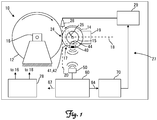
- a tire tread wear test machine is illustrated at 10 in Fig. 1 .
- the test machine 10 includes a rotating element 12 upon which a tire 14 rotates thereon.
- the rotating element 12 can take numerous forms including a large drum or wheel as illustrated or a flat belt assembly having a rotating endless belt, such as disclosed in US Patent 6,584,835 .
- Such systems are available from MTS Systems Corporation of Eden Prairie, Minnesota, USA.
- the rotating element 12 is driven by a drive motor schematically illustrated at 16 and comprising a hydraulic, pneumatic or electric motor.
- the tire 14 is mounted to a suitable wheel 15 (tire and wheel assembly 17) that in turn is mounted to a spindle (i.e. holder) of a wheel positioner, schematically illustrated at 19, which positions the tire 14 upon the rotating element 12.
- the positioner 19 can include various actuators (typically hydraulic, but could also be electric), levers, struts, pivots and the like to adjust the position of the tire and wheel assembly 17 as well as to load (apply a force) the tire 14 upon the rotating element 12. For instance, positioning can include simulated steering position or movement of the tire and wheel assembly 17 about a steering axis 18.
- a material supply system 27 that provides a powder, fluid or other substance to the rotating element 12, the tire 14 and/or otherwise is positioned so as to provide material to the tire contact patch 24.
- the material is provided through a nozzle 28 coupled to a material feeder 29 (hereinafter exemplified as providing powder).
- Material supply systems 27 are well known in the art.
- the receiver 50 is electrically connected to and provides an input signal to a friction estimation processor 60.
- the friction estimation processor 60 provides an estimated value or parameter indicative of friction at the contact patch 24, or another parameter of the tire 14 engaging the rotating element 12.
- the friction estimation processor 60 provides an output signal 64 that forms a command signal to a powder delivery controller 70.
- the powder delivery controller 70 in turn provides a control signal to the powder feeder 29.
- the sensor(s) 40 in the tire 14, along with the friction estimation processor 60 (and any or all of the foregoing hardware to provide an input to the friction estimating processor 60 based on the output signal from the sensor(s) 40) provides a feedback signal to powder delivery controller 70 that adjusts the feed rate of the powder to the tire contact patch 24.
- friction estimation processor 60 need only provide an output signal 64 that can be used to control the application of powder by the powder feeder 29.
- the friction at the tire contact patch 24 ascertained by friction estimation processor 60 can be used to ascertain when a surface (or elements forming the surface) needs to be replaced as indicated by an output signal 67.
- the test machine 10 can measure a length of the tire contact patch 24.
- one or more parameters of the test machine 10 such as any one or more of the parameters of the positioner 19 can be adjusted in order to obtain a desired length of the tire contact patch 24.
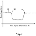
- a value indicative of the length of the tire contact patch 24 is outputted from the tire contact patch length calculation processor 90 as signal 91 and provided to a tire contact patch length regulator 120.
- the calculated value of the length of the tire contact patch 24 as calculated by the tire contact patch length calculation processor 90 can be rendered to a user though a suitable rendering device such as a monitor or a printer. The user can then adjust the gas pressure of the tire and wheel assembly 17 manually using a manually operated control valve with or without the rotary union 127.
- three axis accelerometers may be employed. Multiple accelerometers may be placed across the width of the tire carcass. Multiple sensors could be installed around the circumference of the tire to increase the rate that tire information is provided from the tire. A single sensor provides information once per tire revolution whereas 2 sensor provide information twice per revolution and so on.
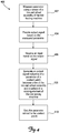
- Figure 5 is a flow chart diagram of another method 500 of operating a tire testing machine.
- Method 500 comprises, in one embodiment, receiving a signal indicative of a parameter of the tire testing machine from an intelligent tire of the tire testing machine in block 502, feeding the signal to a parameter varying system in block 504, and adjusting the parameter based on the feedback signal in block 506.
- processing modules, controllers and regulators indicated above can be implemented with analog and/or digital circuitry. It should also be noted that although separate processing modules, controllers and regulators have been illustrated, this should not be considered limiting wherein this was done in order to provide more clarity for understanding aspects of the invention. Practical embodiments of the tire testing machine 10 may include a single or multiple analog and/or digital circuits to perform one or more of the foregoing processing steps or implement one or more of the controllers, processors and regulators. In addition, it should be understood that the processing steps, or portions thereof, can be performed with hardware and/or software in any combination or portion thereof. The software comprises instructions executed by any suitable processor.
- the processor can be implemented with an electrical circuit having, for instance, a microprocessor and support peripherals such as random access memory (RAM), read only memory (ROM) and/or other computer readable, non-transitory storage mediums communicating with each other over a system bus.
- a circuit board can be used to form the electrical connections for each of the foregoing components and/or one or more components can be implemented as a system-on-a-chip.
- Other components such as analog-to-digital converters, digital-to-analog converters, monitors and user operated input devices (keyboards, pointers, etc.) can also be operably coupled to one or more of the foregoing components such as through the system bus.
Description
- Laboratory tire test machines are known and are used to conduct tire tread wear tests on tires such as rubber treaded pneumatic or non-pneumatic tires. Generally, a tire and wheel assembly is mounted to a spindle where the tire contacts and rolls against a rotating element such as a drum or the like. The rotating element can have a texture to simulate desired road surfaces. In the alternative or in addition, powder (e.g. talc, silica sand) or other forms of particulate matter can be provided at the tire contact patch. The powder or other particulate matter performs two functions during testing. One function is to provide some control of the friction between the artificial test surface on the rotating element and the tire. The second function is to apply dust to the rubber tread wear particles so they do not stick to the tire or rolling element test surface. The tread wear particles can then be removed by a dust collection system. Various powders and particulates are used. Many are proprietary to the test researchers. Tread wear on the tire is also affected by changes to the test surface as testing progresses. It is often desirable to maintain a surface friction within some range for proper testing. Delivering the proper amount of powder and particulates to the tire contact patch to obtain the desired results is necessary.
- On some laboratory tire test machines tire tread wear testing is performed on a curved surface or roller. The curved surface introduces geometry differences in the tire contact patch between testing on the laboratory test machine and real world use of the tire where the contact patch is substantially flat. Adjustments are typically needed to compensate for the test conditions.
- The idea of an "intelligent tire" has been advanced. "Intelligent tires" is a term to indicate that the tires have instrumentation or sensor(s) applied to or embedded in the tire to provide feedback to a monitoring system in a vehicle. Work on "intelligent tires" is progressing at tire companies and universities in order that data from the tire is provided to the vehicle monitoring system indicative of roadway friction, tire contact patch size and tire forces. This information can be used during vehicle operation in order to improve vehicle handling and/or stability. The sensor(s) is installed on/in the tire structure or the tire rim to measure, typically, a mechanical change in the tire structure. An algorithm embodied in a computer readable medium that is executed on a processor either within the tire and wheel assembly or outside of the tire and wheel assembly interprets the signal(s) received from the sensor(s). For instance, one method employed by tire companies and universities is to install one or more accelerometers on the inside surface of the tire carcass body or innerliner near the center plane of the tire. The acceleration signal(s) typically is evaluated by the processor executing the algorithm to determine contact patch surface length and characteristics that are indicative of friction between the tire and roadway. It should be noted aspects of the invention described herein do not pertain to algorithms used to evaluate tire friction, but a merely mentioned herein as background information. The patent document
WO 2012/091719 A1 discloses a system where a sensor embedded in a tire is used within a system for determining the tire load. The patent documentUS 2010/0031740 A1 discloses a test bench for testing a wheel-and-tire assembly including a drum on which the tire to be tested rolls. - The present invention consists of a tire testing machine as defined in claim 1. One aspect disclosed is a tire testing machine having a rotating element, a tire and wheel assembly having a sensor for measuring a parameter related to the tire and wheel assembly as it rotates on the rotating element and providing an output signal indicative thereof, a holder supporting the tire and wheel assembly for rotation against a surface of the rotating element, a processor configured to receive an input at least based on the output signal from the sensor, the processor configured to provide an output signal indicative of a parameter of a contact patch between a tire of the tire and wheel assembly and the rotating element, and a controlled element configured to vary a parameter related to the contact patch. In one embedment, the parameter may be a length of the contact patch.
- The controlled element may include, for example, one or more of a positioner of the holder configured to adjust a position of the tire and wheel assembly relative to the rotating element, a valve configured to adjust a pressure of gas in the tire and wheel assembly, or a material supply system to affect contact of the tire against the rotating element, the material supply system adjusting delivery of material based on an output signal from the processor.
- The rotating element may include, for example, a rotating wheel or a rotating endless belt.
- In another aspect, a tire testing machine includes a rotating element, a tire and wheel assembly having a sensor for measuring a parameter related to the tire and wheel assembly as it rotates on the rotating element and providing an output signal indicative thereof, a holder supporting the tire and wheel assembly for rotation against a surface of the rotating element, a processor configured to receive an input at least based on the output signal from the sensor, the processor configured to provide an output signal indicative of a parameter of friction between a tire of the tire and wheel assembly and the rolling element, and a controlled element configured to vary a parameter related to the friction. The controlled element may be, for example, a material supply system to adjust delivery of material to the tire and the rolling element based on an output signal from the processor.
- In yet another aspect, a method of operating a tire testing machine includes measuring a parameter using a sensor of a tire and wheel assembly of the tire testing machine, providing an output signal based on the measured parameter, receiving an input based on the output signal, generating an output signal indicative of a parameter of a contact patch between a tire of the tire and wheel assembly and a surface of a rotating element of the tire testing machine, and varying the parameter related to the contact patch.
- Generating an output signal may include, for example, estimating friction at the contact patch. Varying the parameter may include, for example, one or more of adjusting a position of the tire and wheel assembly relative to the rotating element, estimating friction at the contact patch, and wherein varying the parameter comprises adjusting a pressure of gas in the tire of the tire and wheel assembly, or varying the parameter comprises adjusting delivery of material to an area of the contact patch.
- The method may also further include one or more of determining when the surface of the rotating element is in need of replacement based on the friction at the contact patch, and determining whether a material delivery system of the tire testing machine is properly functioning based on the friction at the contact patch.
- In still another aspect, a method of operating a tire testing machine includes receiving a signal indicative of a parameter of the tire testing machine from an intelligent tire of the tire testing machine, feeding the signal to a parameter varying system, and adjusting the parameter based on the feedback signal. Adjusting the parameter may include providing feedback from the intelligent tire to the parameter varying system, and varying the parameter by one or more of controlling friction at an area of a contact patch between the intelligent tire and a surface of a rotating element of the tire testing machine, and varying the parameter by controlling air pressure in the intelligent tire.
- In one or more embodiments, the parameter may be rendered to a user.
- Two or more of the foregoing features can be combined together as desired.
-
-
Figure 1 is a schematic view of a tire testing machine according to an embodiment of the present disclosure; -
Figure 2 is a schematic view of a tire testing machine according to another embodiment of the present disclosure; -
Figure 2 is a schematic view of a tire testing machine according to another embodiment of the present disclosure; -
Figure 3 is a graph of accelerometer output of an accelerometer according to an embodiment of the present disclosure; -
Figure 4 is a flow chart of a method according to an embodiment of the present disclosure; and -
Figure 5 is a flow chart diagram of a method according to another embodiment of the present disclosure. - A tire tread wear test machine is illustrated at 10 in
Fig. 1 . Thetest machine 10 includes a rotatingelement 12 upon which atire 14 rotates thereon. The rotatingelement 12 can take numerous forms including a large drum or wheel as illustrated or a flat belt assembly having a rotating endless belt, such as disclosed inUS Patent 6,584,835 . Such systems are available from MTS Systems Corporation of Eden Prairie, Minnesota, USA. - The rotating
element 12 is driven by a drive motor schematically illustrated at 16 and comprising a hydraulic, pneumatic or electric motor. Thetire 14 is mounted to a suitable wheel 15 (tire and wheel assembly 17) that in turn is mounted to a spindle (i.e. holder) of a wheel positioner, schematically illustrated at 19, which positions thetire 14 upon the rotatingelement 12. Thepositioner 19 can include various actuators (typically hydraulic, but could also be electric), levers, struts, pivots and the like to adjust the position of the tire andwheel assembly 17 as well as to load (apply a force) thetire 14 upon the rotatingelement 12. For instance, positioning can include simulated steering position or movement of the tire andwheel assembly 17 about asteering axis 18. Other positioning parameters can also include adjusting the camber of the tire andwheel assembly 17 as it rotates upon the rotatingelement 12. In the embodiment illustrated, the camber adjustment can be about anaxis 20 extending through atire contact patch 24 of thetire 14 with the rotatingelement 12. If desired, the positioner can also adjust acaster angle 25 of thesteering axis 18 relative to a reference axis, for instance, that is perpendicular to the surface of the rotatingelement 12 through the tire contact patch. It should be understood that thepositioner 19 need not provide any or all of the position adjustments of the tire andwheel assembly 17, but rather the foregoing position adjustments of the tire and wheel assembly are merely illustrative. Asystem controller 28 provides control signals to control operation of thetesting machine 10 such as but not limited to themotor 16 and thepositioner 19. - In the embodiment of
Fig. 1 , amaterial supply system 27 that provides a powder, fluid or other substance to therotating element 12, thetire 14 and/or otherwise is positioned so as to provide material to thetire contact patch 24. In the embodiment illustrated, the material is provided through anozzle 28 coupled to a material feeder 29 (hereinafter exemplified as providing powder).Material supply systems 27 are well known in the art. - One or
more sensors 40 are disposed on or in the tire andwheel assembly 17 so as to provide output signal(s) indicative of measured parameter(s). The output signal(s) from the sensor(s) 40 are typically to a transmitter or processing module 41 that can include a transmitter 42, if desired. The processing module 41 can be mounted to thetire 14 along with the sensor(s) 40, or be mounted to thewheel 15, such as indicated at 44. Typically, the transmitter 42 is wirelessly coupled to areceiver 50 as illustrated, although if desired, a wired signal transmission system can couple the sensor(s) 40, processing module 41, and/or transmitter 42 directly to areceiver 50 using a wired connection formed with a slip ring assembly, not shown, but provided on a tire andwheel assembly 17. - The
receiver 50 is electrically connected to and provides an input signal to afriction estimation processor 60. Thefriction estimation processor 60 provides an estimated value or parameter indicative of friction at thecontact patch 24, or another parameter of thetire 14 engaging therotating element 12. In the embodiment illustrated, thefriction estimation processor 60 provides anoutput signal 64 that forms a command signal to apowder delivery controller 70. Thepowder delivery controller 70 in turn provides a control signal to thepowder feeder 29. The sensor(s) 40 in thetire 14, along with the friction estimation processor 60 (and any or all of the foregoing hardware to provide an input to thefriction estimating processor 60 based on the output signal from the sensor(s) 40) provides a feedback signal topowder delivery controller 70 that adjusts the feed rate of the powder to thetire contact patch 24. It should be noted aspects of the invention described herein do not pertain to algorithms used byfriction estimation processor 60 to evaluate tire friction. For purposes of aspects of the invention,friction estimation processor 60 need only provide anoutput signal 64 that can be used to control the application of powder by thepowder feeder 29. In another embodiment, the friction at thetire contact patch 24 ascertained byfriction estimation processor 60 can be used to ascertain when a surface (or elements forming the surface) needs to be replaced as indicated by anoutput signal 67. - It should be noted that the calculated friction or other parameter of the tire and
wheel assembly 17 or at thetire contact patch 24 can also be rendered to a user by any suitable device such as a monitor, printer or electronic file recording device. A desired value of the parameter such as friction at thetire contact patch 24, for example, can be obtained, or maintained within a desired range by the user. Likewise, if desired, the friction at thetire contact patch 24 can be adjusted using thepowder feeder 29 as controlled by thepowder delivery controller 70 and associated equipment described above throughout or during a test, thereby, providing the user the ability to create more complicated and/or real world tire tests. - In addition, or in the alternative to adjusting the friction of the
tire 14 upon therotating element 12 at thetire contact patch 24, thetest machine 10 can measure a length of thetire contact patch 24. With measurement of the length of thetire contact patch 24, one or more parameters of thetest machine 10 such as any one or more of the parameters of thepositioner 19 can be adjusted in order to obtain a desired length of thetire contact patch 24. -
Fig. 2 schematically illustrates another technique for adjusting a length of thetire contact patch 24 that can be used by itself or in conjunction with adjusting one or more of the parameters of thepositioner 19. In particular, adjustment of the length of thetire contact patch 24 inFig. 2 is obtained by adjusting or regulating the gas pressure in the tire andwheel assembly 17. By measuring the length of thetire contact patch 24, the gas pressure can be adjusted (and/or other parameters of the test machine can be adjusted) so as to obtain the desired length of thetire contact patch 24. Adjustment of the length of thetire contact patch 24 is particularly advantageous when thetest machine 10 includes a round drum, wheel or the like that provides a curved surface upon which thetire 14 rotates. Using the sensor(s) 40, processing module 41, transmitter 42 and/orreceiver 50, aninput signal 80 is provided to a tire contact patchlength calculation processor 90 that calculates the length of thetire contact patch 24, which is provided as anoutput signal 91. - Referring to
Fig. 3 , in one illustrative embodiment, the sensor(s) 40 can each comprise an accelerometer that provides an output signal that varies over one revolution of thetire 14. In particular, the accelerometer can provide a signal indicated at 80 that is substantially constant during rotation of thetire 14 but for at thetire contact patch 24. As illustrated inFig. 3 , when thetire 14 contacts the surface of the rollingelement 12 at the beginning of thetire contact patch 24, the accelerometer senses this contact as indicated at 102 inFig. 3 . Another change in the output signal from the accelerometer is indicated at 104, which corresponds to the end of thetire contact patch 24 or where the portion of thetire 14 having thesensor 40 leaves or disengages from the surface of therotating element 12. By measuring the time between the changes in the output signal betweenpoints wheel assembly 17 between these points, or using other suitable processing techniques that can include other parameters of the tire andwheel assembly 17 ortest machine 10 as needed, such as but not limited to the rotational speed of the tire andwheel assembly 17, a value indicative of the length of thetire contact patch 24 is outputted from the tire contact patchlength calculation processor 90 assignal 91 and provided to a tire contactpatch length regulator 120. The tire contactpatch length regulator 120 compares the output receipt from the tire contact patchlength calculation processor 90 with asignal 130 indicative of the desired length of thetire contact patch 24 and provides, in the embodiment illustrated, anoutput signal 122 to a tireinflation pressure controller 124 that in turn controls avalve 126 connected to anair supply 132 in order to increase or decrease the gas pressure in the tire andwheel assembly 17 viaair hose 134. In the embodiment illustrated, thevalve 126 andhose 134 are operably coupled through arotary union 127 to the tire andwheel assembly 17 so as to allow the gas pressure to be adjusted as the tire andwheel assembly 17 rotates. It should be noted in another embodiment, if desired, the calculated value of the length of thetire contact patch 24 as calculated by the tire contact patchlength calculation processor 90 can be rendered to a user though a suitable rendering device such as a monitor or a printer. The user can then adjust the gas pressure of the tire andwheel assembly 17 manually using a manually operated control valve with or without therotary union 127. - For example, three axis accelerometers may be employed. Multiple accelerometers may be placed across the width of the tire carcass. Multiple sensors could be installed around the circumference of the tire to increase the rate that tire information is provided from the tire. A single sensor provides information once per tire revolution whereas 2 sensor provide information twice per revolution and so on.
-
Figure 4 is a flow chart diagram of amethod 400 of operating a tire testing machine.Method 400 comprises, in one embodiment, measuring a parameter using a sensor of a tire and wheel assembly of the tire testing machine inblock 402, providing an output signal based on the measured parameter inblock 404, receiving an input based on the output signal inblock 406, generating an output signal indicative of a parameter of a contact patch between a tire of the tire and wheel assembly and a surface of a rotating element of the tire testing machine inblock 408, and varying the parameter related to the contact patch inblock 410. -
Figure 5 is a flow chart diagram of anothermethod 500 of operating a tire testing machine.Method 500 comprises, in one embodiment, receiving a signal indicative of a parameter of the tire testing machine from an intelligent tire of the tire testing machine inblock 502, feeding the signal to a parameter varying system inblock 504, and adjusting the parameter based on the feedback signal inblock 506. - It should also be understood that in the embodiments provided above if desired a plurality of
sensors 40 can be disposed along the width of thetire 14 to measure the length of thetire contact patch 24 at selected locations along the width of thetire 14. - Each of the processing modules, controllers and regulators indicated above can be implemented with analog and/or digital circuitry. It should also be noted that although separate processing modules, controllers and regulators have been illustrated, this should not be considered limiting wherein this was done in order to provide more clarity for understanding aspects of the invention. Practical embodiments of the
tire testing machine 10 may include a single or multiple analog and/or digital circuits to perform one or more of the foregoing processing steps or implement one or more of the controllers, processors and regulators. In addition, it should be understood that the processing steps, or portions thereof, can be performed with hardware and/or software in any combination or portion thereof. The software comprises instructions executed by any suitable processor. The processor can be implemented with an electrical circuit having, for instance, a microprocessor and support peripherals such as random access memory (RAM), read only memory (ROM) and/or other computer readable, non-transitory storage mediums communicating with each other over a system bus. A circuit board can be used to form the electrical connections for each of the foregoing components and/or one or more components can be implemented as a system-on-a-chip. Other components such as analog-to-digital converters, digital-to-analog converters, monitors and user operated input devices (keyboards, pointers, etc.) can also be operably coupled to one or more of the foregoing components such as through the system bus. - Although the subject matter has been described in language specific to structural features and/or methodological acts, it is to be understood that the subject matter defined in the appended claims is not necessarily limited to the specific features or acts described above as has been held by the courts. Rather, the specific features and acts described above are disclosed as example forms of implementing the claims.
Claims (10)
- A tire testing machine (10) comprising:a rotating element, the rotating element driven by a motor;a tire and wheel assembly (17) having a sensor 940) configured to measure a parameter related to the tire and wheel assembly as it rotates on the rotating element and providing an output signal indicative thereof;a holder (19) supporting the tire and wheel assembly for rotation against a surface of the rotating element;a processor (64, 91) configured to receive an input at least based on the output signal from the sensor, the processor configured to provide an output signal indicative of at least one of a parameter of a contact patch (24) between a tire (14) of the tire and wheel assembly and the rotating element or a parameter of friction between a tire of the tire and wheel assembly and the rotating element (12); anda controlled element (29, 132) configured to vary a parameter related to the contact patch or a parameter related to the friction respectively.
- The tire testing machine of claim 1 wherein the controlled element (29, 132) is a positioner of the holder (19) configured to adjust a position of the tire and wheel assembly relative to the rotating element (12).
- The tire testing machine of claim 1 wherein the controlled element (29, 132) comprises a valve configured to adjust a pressure of gas in the tire and wheel assembly.
- The tire testing machine of any one of claims 1-3, and further comprising a material supply system (27) to affect contact of the tire (14) against the rotating element (12), the material supply system adjusting delivery of material based on an output signal from the processor.
- The tire testing machine of any one of claims 1-4, wherein the parameter comprises a length of the contact patch (24).
- The tire testing machine of any one of claims 1-5, wherein the rotating element (12) comprises a rotating wheel and/or a rotating endless belt.
- A method of operating a tire testing machine (10), comprising:measuring a parameter using a sensor (40) of a tire and wheel assembly (17)of the tire testing machine;providing an output signal based on the measured parameter;receiving an input based on the output signal;generating an output signal indicative of a parameter of a contact patch (24) between a tire (14) of the tire and wheel assembly and a surface of a rotating element (12) of the tire testing machine, wherein the rotating element is driven by a motor; andvarying the parameter related to the contact patch.
- The method of claim 7, wherein generating an output signal comprises estimating friction at the contact patch (24), and further comprising at least one of varying the parameter comprising adjusting a position of the tire and wheel assembly (17) relative to the rotating element (12); and varying the parameter comprising adjusting a pressure of gas in the tire of the tire and wheel assembly; and adjusting delivery of material to an area of the contact patch; and determining when the surface of the rotating element is in need of replacement based on the friction at the contact patch (24); and determining whether a material delivery system of the tire testing machine is properly functioning based on the friction at the contact patch.
- The method of any one of claims 7-8, and further comprising rendering the parameter to a user.
- The method of any one of claims 7-9, wherein the rotating element (12) comprises a rotating endless belt and/or a rotating wheel.
Applications Claiming Priority (2)
| Application Number | Priority Date | Filing Date | Title |
|---|---|---|---|
| US201361861228P | 2013-08-01 | 2013-08-01 | |
| PCT/US2014/049371 WO2015017758A1 (en) | 2013-08-01 | 2014-08-01 | Tire testing apparatus |
Publications (2)
| Publication Number | Publication Date |
|---|---|
| EP3028029A1 EP3028029A1 (en) | 2016-06-08 |
| EP3028029B1 true EP3028029B1 (en) | 2020-05-27 |
Family
ID=51383930
Family Applications (1)
| Application Number | Title | Priority Date | Filing Date |
|---|---|---|---|
| EP14753179.2A Active EP3028029B1 (en) | 2013-08-01 | 2014-08-01 | Tire testing apparatus |
Country Status (6)
| Country | Link |
|---|---|
| US (1) | US9739690B2 (en) |
| EP (1) | EP3028029B1 (en) |
| JP (1) | JP6373380B2 (en) |
| KR (1) | KR102319564B1 (en) |
| CN (1) | CN105452837B (en) |
| WO (1) | WO2015017758A1 (en) |
Families Citing this family (5)
| Publication number | Priority date | Publication date | Assignee | Title |
|---|---|---|---|---|
| GB2544299B (en) * | 2015-11-11 | 2020-11-11 | Jaguar Land Rover Ltd | Improvements in or relating to tyre testing procedures |
| WO2019005529A1 (en) | 2017-06-30 | 2019-01-03 | Bridgestone Americas Tire Operations, Llc | Enclosure system for indoor tire testing |
| JP7154614B2 (en) * | 2017-08-03 | 2022-10-18 | 国際計測器株式会社 | Spreader and tire tester |
| WO2021217237A1 (en) * | 2020-04-29 | 2021-11-04 | Whitewater West Industries Ltd. | Apparatus, system, and method for determining an attribute of a ride vehicle |
| KR102324861B1 (en) * | 2020-05-27 | 2021-11-11 | 한국도로공사 | Measuring system of the paved road wear and fine dusts and method thereof |
Family Cites Families (21)
| Publication number | Priority date | Publication date | Assignee | Title |
|---|---|---|---|---|
| JPS559650B2 (en) * | 1973-08-08 | 1980-03-11 | ||
| US4594878A (en) * | 1983-06-24 | 1986-06-17 | Nippo Sangyo Co. Ltd. | Dynamic friction coefficient measuring apparatus |
| US4704900A (en) * | 1986-08-19 | 1987-11-10 | Eagle-Picher Industries, Inc. | Apparatus and method for imposing a desired average radial force on a tire |
| JP3274538B2 (en) * | 1993-06-16 | 2002-04-15 | 株式会社ブリヂストン | A method for preventing adhesion of wear rubber in a tire indoor wear test and a powder spraying device. |
| JPH07146217A (en) * | 1993-11-25 | 1995-06-06 | Sumitomo Rubber Ind Ltd | Wear testing method for tire |
| US6050876A (en) | 1997-08-08 | 2000-04-18 | Cabot Corporation | Automated abrader |
| WO2001008908A1 (en) * | 1999-07-30 | 2001-02-08 | Pirelli Pneumatici S.P.A. | Method and system for controlling the behaviour of a vehicle by controlling its tyres |
| US6584835B2 (en) | 2000-02-11 | 2003-07-01 | Mts Systems Corporation | Spindle assembly for a tire or wheel testing machine |
| JP4357074B2 (en) * | 2000-03-17 | 2009-11-04 | 株式会社ブリヂストン | Tire wear prediction method and tire wear prediction apparatus |
| JP4169673B2 (en) * | 2003-10-09 | 2008-10-22 | 横浜ゴム株式会社 | Tire wear test method and tire wear tester |
| JP2005164337A (en) * | 2003-12-01 | 2005-06-23 | Toyota Motor Corp | Tire state estimation system |
| JP4358035B2 (en) * | 2004-06-02 | 2009-11-04 | 株式会社ブリヂストン | Method and apparatus for estimating road friction coefficient |
| JP5183114B2 (en) * | 2007-07-11 | 2013-04-17 | 株式会社ブリヂストン | Tire wear estimation method and tire wear estimation apparatus |
| WO2009152129A1 (en) * | 2008-06-09 | 2009-12-17 | Mts Systems Corporation | Flat belt roadway simulator with steer and/or camber adjustment and method for ascertaining rolling loss |
| DE102009036145A1 (en) * | 2008-08-05 | 2010-04-29 | Link Engineering Company, Plymouth | Biaxial wheel test arrangement |
| US20100271191A1 (en) * | 2008-10-07 | 2010-10-28 | De Graff Bassel | Systems, devices, and methods utilizing stretchable electronics to measure tire or road surface conditions |
| JP4979740B2 (en) * | 2009-06-17 | 2012-07-18 | 株式会社神戸製鋼所 | Pneumatic circuit of tire test apparatus, tire test apparatus and tire test method |
| EP2634016B1 (en) * | 2010-02-17 | 2017-12-20 | Snap-on Equipment Srl a unico socio | Tyre changer and a method of measuring force variations acting between a peripheral surface of a wheel/tyre assembly and a roller |
| CN103347712B (en) | 2010-12-30 | 2015-11-25 | 米其林集团总公司 | For determining the system and method based on piezoelectricity of loading of tire |
| EP2540529B1 (en) * | 2011-06-28 | 2015-08-12 | Snap-on Equipment Srl a unico socio | Automatic rim centering system for a tyre changing machine |
| JP5412494B2 (en) * | 2011-11-22 | 2014-02-12 | 住友ゴム工業株式会社 | Evaluation method of bead durability of heavy duty tires |
-
2014
- 2014-08-01 KR KR1020167003126A patent/KR102319564B1/en active IP Right Grant
- 2014-08-01 WO PCT/US2014/049371 patent/WO2015017758A1/en active Application Filing
- 2014-08-01 US US14/449,380 patent/US9739690B2/en active Active
- 2014-08-01 EP EP14753179.2A patent/EP3028029B1/en active Active
- 2014-08-01 CN CN201480043449.4A patent/CN105452837B/en active Active
- 2014-08-01 JP JP2016531927A patent/JP6373380B2/en active Active
Non-Patent Citations (1)
| Title |
|---|
| None * |
Also Published As
| Publication number | Publication date |
|---|---|
| WO2015017758A1 (en) | 2015-02-05 |
| CN105452837B (en) | 2019-05-03 |
| KR20160036565A (en) | 2016-04-04 |
| EP3028029A1 (en) | 2016-06-08 |
| CN105452837A (en) | 2016-03-30 |
| JP6373380B2 (en) | 2018-08-15 |
| US9739690B2 (en) | 2017-08-22 |
| JP2016527516A (en) | 2016-09-08 |
| US20150033840A1 (en) | 2015-02-05 |
| KR102319564B1 (en) | 2021-10-29 |
Similar Documents
| Publication | Publication Date | Title |
|---|---|---|
| EP3028029B1 (en) | Tire testing apparatus | |
| EP3020578A1 (en) | Tire wear compensated load estimation system and method | |
| JP4904260B2 (en) | Control method for multi-axis wheel fatigue system | |
| KR101298777B1 (en) | Driving control method of tire testing machine and tire testing machine | |
| BRPI0419077B1 (en) | method and system for determining a bending angle of a tire during vehicle advancement, and method for controlling a vehicle having at least one tire installed thereon during advancement of said vehicle | |
| BRPI0318554B1 (en) | method and system for determining the load on a vehicle mounted tire while driving said vehicle on a tread and method for controlling a vehicle having at least one tire mounted on it | |
| US9840234B2 (en) | Inflator with reactive tire pressure monitoring | |
| CN107179199A (en) | A kind of Electric Motor Wheel comprehensive performance test simulation system | |
| JP4963978B2 (en) | Rubber abrasion tester and tire tread rubber abrasion test method using the same | |
| JP2001512822A (en) | Automatic wear test equipment | |
| CN108146161B (en) | Wheel imbalance detection system and method | |
| JP2014190945A (en) | Method and device of testing rubber abrasion | |
| CN110146306A (en) | A kind of rolling resistance test device and rolling resistance test method | |
| WO2016056433A1 (en) | Method for estimating load model in tyre uniformity tester | |
| WO2020115940A1 (en) | Tire ground contact characteristic measuring method, tire ground contact characteristic measuring device, and tire ground contact characteristic measuring system | |
| JP3821396B2 (en) | Adaptive warm-up method for force fluctuation machines | |
| JP2017090407A (en) | Rubber friction abrasion testing method | |
| WO2022229993A1 (en) | Calibration method and system of a sensor for tyres | |
| KR20000029632A (en) | Method of enhancing the measurement accuracy of a tire uniformity machine | |
| BRPI0318560B1 (en) | Method and system for determining an angle of deviation of a tire mounted on a moving vehicle, and method for controlling a moving vehicle | |
| BRPI0318387B1 (en) | METHOD FOR DETERMINING A POSITION PERFORMED ON A TIRE MOUNTED IN A VEHICLE DURING THE OPERATION OF THE VEHICLE ON A ROLLING SURFACE METHOD FOR CONTROLLING A VEHICLE HAVING AT LEAST A MOUNTED ON THE VEHICLE AND A SYSTEM FOR A DETERMINED MOUNTED ON A VEHICLE DURING THE OPERATION OF THE VEHICLE ON A ROAD SURFACE |
Legal Events
| Date | Code | Title | Description |
|---|---|---|---|
| PUAI | Public reference made under article 153(3) epc to a published international application that has entered the european phase |
Free format text: ORIGINAL CODE: 0009012 |
|
| 17P | Request for examination filed |
Effective date: 20160229 |
|
| AK | Designated contracting states |
Kind code of ref document: A1 Designated state(s): AL AT BE BG CH CY CZ DE DK EE ES FI FR GB GR HR HU IE IS IT LI LT LU LV MC MK MT NL NO PL PT RO RS SE SI SK SM TR |
|
| AX | Request for extension of the european patent |
Extension state: BA ME |
|
| DAX | Request for extension of the european patent (deleted) | ||
| STAA | Information on the status of an ep patent application or granted ep patent |
Free format text: STATUS: EXAMINATION IS IN PROGRESS |
|
| 17Q | First examination report despatched |
Effective date: 20181217 |
|
| GRAP | Despatch of communication of intention to grant a patent |
Free format text: ORIGINAL CODE: EPIDOSNIGR1 |
|
| STAA | Information on the status of an ep patent application or granted ep patent |
Free format text: STATUS: GRANT OF PATENT IS INTENDED |
|
| INTG | Intention to grant announced |
Effective date: 20200107 |
|
| GRAS | Grant fee paid |
Free format text: ORIGINAL CODE: EPIDOSNIGR3 |
|
| GRAA | (expected) grant |
Free format text: ORIGINAL CODE: 0009210 |
|
| STAA | Information on the status of an ep patent application or granted ep patent |
Free format text: STATUS: THE PATENT HAS BEEN GRANTED |
|
| AK | Designated contracting states |
Kind code of ref document: B1 Designated state(s): AL AT BE BG CH CY CZ DE DK EE ES FI FR GB GR HR HU IE IS IT LI LT LU LV MC MK MT NL NO PL PT RO RS SE SI SK SM TR |
|
| REG | Reference to a national code |
Ref country code: GB Ref legal event code: FG4D |
|
| REG | Reference to a national code |
Ref country code: CH Ref legal event code: EP |
|
| REG | Reference to a national code |
Ref country code: AT Ref legal event code: REF Ref document number: 1275036 Country of ref document: AT Kind code of ref document: T Effective date: 20200615 |
|
| REG | Reference to a national code |
Ref country code: DE Ref legal event code: R096 Ref document number: 602014065917 Country of ref document: DE |
|
| REG | Reference to a national code |
Ref country code: LT Ref legal event code: MG4D |
|
| PG25 | Lapsed in a contracting state [announced via postgrant information from national office to epo] |
Ref country code: SE Free format text: LAPSE BECAUSE OF FAILURE TO SUBMIT A TRANSLATION OF THE DESCRIPTION OR TO PAY THE FEE WITHIN THE PRESCRIBED TIME-LIMIT Effective date: 20200527 Ref country code: LT Free format text: LAPSE BECAUSE OF FAILURE TO SUBMIT A TRANSLATION OF THE DESCRIPTION OR TO PAY THE FEE WITHIN THE PRESCRIBED TIME-LIMIT Effective date: 20200527 Ref country code: GR Free format text: LAPSE BECAUSE OF FAILURE TO SUBMIT A TRANSLATION OF THE DESCRIPTION OR TO PAY THE FEE WITHIN THE PRESCRIBED TIME-LIMIT Effective date: 20200828 Ref country code: FI Free format text: LAPSE BECAUSE OF FAILURE TO SUBMIT A TRANSLATION OF THE DESCRIPTION OR TO PAY THE FEE WITHIN THE PRESCRIBED TIME-LIMIT Effective date: 20200527 Ref country code: NO Free format text: LAPSE BECAUSE OF FAILURE TO SUBMIT A TRANSLATION OF THE DESCRIPTION OR TO PAY THE FEE WITHIN THE PRESCRIBED TIME-LIMIT Effective date: 20200827 Ref country code: IS Free format text: LAPSE BECAUSE OF FAILURE TO SUBMIT A TRANSLATION OF THE DESCRIPTION OR TO PAY THE FEE WITHIN THE PRESCRIBED TIME-LIMIT Effective date: 20200927 Ref country code: PT Free format text: LAPSE BECAUSE OF FAILURE TO SUBMIT A TRANSLATION OF THE DESCRIPTION OR TO PAY THE FEE WITHIN THE PRESCRIBED TIME-LIMIT Effective date: 20200928 |
|
| REG | Reference to a national code |
Ref country code: NL Ref legal event code: MP Effective date: 20200527 |
|
| PG25 | Lapsed in a contracting state [announced via postgrant information from national office to epo] |
Ref country code: LV Free format text: LAPSE BECAUSE OF FAILURE TO SUBMIT A TRANSLATION OF THE DESCRIPTION OR TO PAY THE FEE WITHIN THE PRESCRIBED TIME-LIMIT Effective date: 20200527 Ref country code: HR Free format text: LAPSE BECAUSE OF FAILURE TO SUBMIT A TRANSLATION OF THE DESCRIPTION OR TO PAY THE FEE WITHIN THE PRESCRIBED TIME-LIMIT Effective date: 20200527 Ref country code: BG Free format text: LAPSE BECAUSE OF FAILURE TO SUBMIT A TRANSLATION OF THE DESCRIPTION OR TO PAY THE FEE WITHIN THE PRESCRIBED TIME-LIMIT Effective date: 20200827 Ref country code: RS Free format text: LAPSE BECAUSE OF FAILURE TO SUBMIT A TRANSLATION OF THE DESCRIPTION OR TO PAY THE FEE WITHIN THE PRESCRIBED TIME-LIMIT Effective date: 20200527 |
|
| REG | Reference to a national code |
Ref country code: AT Ref legal event code: MK05 Ref document number: 1275036 Country of ref document: AT Kind code of ref document: T Effective date: 20200527 |
|
| PG25 | Lapsed in a contracting state [announced via postgrant information from national office to epo] |
Ref country code: NL Free format text: LAPSE BECAUSE OF FAILURE TO SUBMIT A TRANSLATION OF THE DESCRIPTION OR TO PAY THE FEE WITHIN THE PRESCRIBED TIME-LIMIT Effective date: 20200527 Ref country code: AL Free format text: LAPSE BECAUSE OF FAILURE TO SUBMIT A TRANSLATION OF THE DESCRIPTION OR TO PAY THE FEE WITHIN THE PRESCRIBED TIME-LIMIT Effective date: 20200527 |
|
| PG25 | Lapsed in a contracting state [announced via postgrant information from national office to epo] |
Ref country code: RO Free format text: LAPSE BECAUSE OF FAILURE TO SUBMIT A TRANSLATION OF THE DESCRIPTION OR TO PAY THE FEE WITHIN THE PRESCRIBED TIME-LIMIT Effective date: 20200527 Ref country code: IT Free format text: LAPSE BECAUSE OF FAILURE TO SUBMIT A TRANSLATION OF THE DESCRIPTION OR TO PAY THE FEE WITHIN THE PRESCRIBED TIME-LIMIT Effective date: 20200527 Ref country code: CZ Free format text: LAPSE BECAUSE OF FAILURE TO SUBMIT A TRANSLATION OF THE DESCRIPTION OR TO PAY THE FEE WITHIN THE PRESCRIBED TIME-LIMIT Effective date: 20200527 Ref country code: DK Free format text: LAPSE BECAUSE OF FAILURE TO SUBMIT A TRANSLATION OF THE DESCRIPTION OR TO PAY THE FEE WITHIN THE PRESCRIBED TIME-LIMIT Effective date: 20200527 Ref country code: ES Free format text: LAPSE BECAUSE OF FAILURE TO SUBMIT A TRANSLATION OF THE DESCRIPTION OR TO PAY THE FEE WITHIN THE PRESCRIBED TIME-LIMIT Effective date: 20200527 Ref country code: SM Free format text: LAPSE BECAUSE OF FAILURE TO SUBMIT A TRANSLATION OF THE DESCRIPTION OR TO PAY THE FEE WITHIN THE PRESCRIBED TIME-LIMIT Effective date: 20200527 Ref country code: EE Free format text: LAPSE BECAUSE OF FAILURE TO SUBMIT A TRANSLATION OF THE DESCRIPTION OR TO PAY THE FEE WITHIN THE PRESCRIBED TIME-LIMIT Effective date: 20200527 Ref country code: AT Free format text: LAPSE BECAUSE OF FAILURE TO SUBMIT A TRANSLATION OF THE DESCRIPTION OR TO PAY THE FEE WITHIN THE PRESCRIBED TIME-LIMIT Effective date: 20200527 |
|
| PG25 | Lapsed in a contracting state [announced via postgrant information from national office to epo] |
Ref country code: SK Free format text: LAPSE BECAUSE OF FAILURE TO SUBMIT A TRANSLATION OF THE DESCRIPTION OR TO PAY THE FEE WITHIN THE PRESCRIBED TIME-LIMIT Effective date: 20200527 Ref country code: PL Free format text: LAPSE BECAUSE OF FAILURE TO SUBMIT A TRANSLATION OF THE DESCRIPTION OR TO PAY THE FEE WITHIN THE PRESCRIBED TIME-LIMIT Effective date: 20200527 |
|
| REG | Reference to a national code |
Ref country code: DE Ref legal event code: R097 Ref document number: 602014065917 Country of ref document: DE |
|
| PG25 | Lapsed in a contracting state [announced via postgrant information from national office to epo] |
Ref country code: MC Free format text: LAPSE BECAUSE OF FAILURE TO SUBMIT A TRANSLATION OF THE DESCRIPTION OR TO PAY THE FEE WITHIN THE PRESCRIBED TIME-LIMIT Effective date: 20200527 |
|
| REG | Reference to a national code |
Ref country code: CH Ref legal event code: PL |
|
| PLBE | No opposition filed within time limit |
Free format text: ORIGINAL CODE: 0009261 |
|
| STAA | Information on the status of an ep patent application or granted ep patent |
Free format text: STATUS: NO OPPOSITION FILED WITHIN TIME LIMIT |
|
| GBPC | Gb: european patent ceased through non-payment of renewal fee |
Effective date: 20200827 |
|
| PG25 | Lapsed in a contracting state [announced via postgrant information from national office to epo] |
Ref country code: LI Free format text: LAPSE BECAUSE OF NON-PAYMENT OF DUE FEES Effective date: 20200831 Ref country code: CH Free format text: LAPSE BECAUSE OF NON-PAYMENT OF DUE FEES Effective date: 20200831 Ref country code: LU Free format text: LAPSE BECAUSE OF NON-PAYMENT OF DUE FEES Effective date: 20200801 |
|
| 26N | No opposition filed |
Effective date: 20210302 |
|
| REG | Reference to a national code |
Ref country code: BE Ref legal event code: MM Effective date: 20200831 |
|
| PG25 | Lapsed in a contracting state [announced via postgrant information from national office to epo] |
Ref country code: SI Free format text: LAPSE BECAUSE OF FAILURE TO SUBMIT A TRANSLATION OF THE DESCRIPTION OR TO PAY THE FEE WITHIN THE PRESCRIBED TIME-LIMIT Effective date: 20200527 |
|
| PG25 | Lapsed in a contracting state [announced via postgrant information from national office to epo] |
Ref country code: BE Free format text: LAPSE BECAUSE OF NON-PAYMENT OF DUE FEES Effective date: 20200831 Ref country code: IE Free format text: LAPSE BECAUSE OF NON-PAYMENT OF DUE FEES Effective date: 20200801 Ref country code: GB Free format text: LAPSE BECAUSE OF NON-PAYMENT OF DUE FEES Effective date: 20200827 |
|
| PG25 | Lapsed in a contracting state [announced via postgrant information from national office to epo] |
Ref country code: TR Free format text: LAPSE BECAUSE OF FAILURE TO SUBMIT A TRANSLATION OF THE DESCRIPTION OR TO PAY THE FEE WITHIN THE PRESCRIBED TIME-LIMIT Effective date: 20200527 Ref country code: MT Free format text: LAPSE BECAUSE OF FAILURE TO SUBMIT A TRANSLATION OF THE DESCRIPTION OR TO PAY THE FEE WITHIN THE PRESCRIBED TIME-LIMIT Effective date: 20200527 Ref country code: CY Free format text: LAPSE BECAUSE OF FAILURE TO SUBMIT A TRANSLATION OF THE DESCRIPTION OR TO PAY THE FEE WITHIN THE PRESCRIBED TIME-LIMIT Effective date: 20200527 |
|
| PG25 | Lapsed in a contracting state [announced via postgrant information from national office to epo] |
Ref country code: MK Free format text: LAPSE BECAUSE OF FAILURE TO SUBMIT A TRANSLATION OF THE DESCRIPTION OR TO PAY THE FEE WITHIN THE PRESCRIBED TIME-LIMIT Effective date: 20200527 |
|
| P01 | Opt-out of the competence of the unified patent court (upc) registered |
Effective date: 20230531 |
|
| PGFP | Annual fee paid to national office [announced via postgrant information from national office to epo] |
Ref country code: FR Payment date: 20230825 Year of fee payment: 10 Ref country code: DE Payment date: 20230829 Year of fee payment: 10 |