EP1136263B1 - Dispositif pour transporter une feuille pour une machine d'impression rotative - Google Patents
Dispositif pour transporter une feuille pour une machine d'impression rotative Download PDFInfo
- Publication number
- EP1136263B1 EP1136263B1 EP01103697.7A EP01103697A EP1136263B1 EP 1136263 B1 EP1136263 B1 EP 1136263B1 EP 01103697 A EP01103697 A EP 01103697A EP 1136263 B1 EP1136263 B1 EP 1136263B1
- Authority
- EP
- European Patent Office
- Prior art keywords
- sheet
- grippers
- gripper
- trailing
- suction
- Prior art date
- Legal status (The legal status is an assumption and is not a legal conclusion. Google has not performed a legal analysis and makes no representation as to the accuracy of the status listed.)
- Revoked
Links
Images


Classifications
-
- B—PERFORMING OPERATIONS; TRANSPORTING
- B41—PRINTING; LINING MACHINES; TYPEWRITERS; STAMPS
- B41F—PRINTING MACHINES OR PRESSES
- B41F21/00—Devices for conveying sheets through printing apparatus or machines
- B41F21/10—Combinations of transfer drums and grippers
- B41F21/102—Combinations of transfer drums and grippers with pneumatic means
Definitions
- the invention relates to a device for transporting a sheet for a sheet-processing machine, in particular a Rotationsduckmaschine, in a processing direction with operatively rotating in a first direction first grippers for detecting the arc on an advancing in the processing direction gripper edge, a cylinder carrying the first gripper with a support surface formed on its circumference for the sheet gripped by the first gripper, operatively rotating in a second direction opposite to the first direction second grippers which take over the leading gripper edge from the first grippers and at least one pair operatively in the second direction around one Rotary axis of rotating arch supports, each having a concentric to the axis of rotation rolling surface whose extent along the axis of rotation is smaller than the width of a respective pressure-free side edge d bow and which presses the sheet within a respective side edge in areas of common normal of the support surface and the rolling surfaces to the support surface, as well as a machine equipped with the sheet processing machine, in particular a rotary printing press.
- a device of the type mentioned is from the document JP SHO 55-18194 Y2 known and used according to this, to pass a printed sheet from a printing unit to a boom comprising an endless conveyor with arranged on rotating gripper jaws grippers, by means of which a leading gripper edge of the sheet detectable and the sheet after leaving the printing cylinder in itself left behind trailing edge of the sheet is notedortransportierbar.
- this merely ensures that the sheet is forcibly guided on the pressure-free side edges thereof until its trailing edge passes through the regions of the common normal of the rolling surfaces and the support surface of the printing cylinder.
- the German patent no. 627 851 is a proposal for realizing the detection of the trailing gripper edge by means of trailing edge grippers removed.
- the sheet is taken by means of leading edge grippers of a printing cylinder and pulled by means of the leading edge gripper first chain drive over guide rails extending below the arch pulling down the bottom strand of the first chain drive along these strands.
- a second chain drive is arranged, whose upper strands move in the same direction as the lower strands of the first chain drive.
- the second chain drive carries rear edge gripper, which should detect the trailing gripper edge when this gripper edge of the supported on the guide rail arc has reached a place where leave the upper strands of the second chain drive with respect to the direction of these Trume upstream deflecting.
- the trailing gripper edge of the sheet is prevented from descending below a predetermined level by means of the guide rails, it is not ensured that said gripper edge does not whip after running onto the guide rails.
- this concept is only suitable for Perfecting, and only if any markings occurring on the unprinted side of the sheet can be accepted by its loops on the guide rails, especially in a subsequent printing the back of the sheet in another pass unlikely to apply.
- the US 2,757,610 shows a turning device with a storage drum and a downstream of this in the sheet transport direction turning drum.
- the turning drum has a gripper system for selectively gripping a sheet leading edge (straight printing operation) or sheet trailing edge (reverse printing operation).
- the DE 3036790 shows a turning device with a storage drum, a storage drum upstream transfer drum and a storage drum downstream turning drum.
- the storage drum has grippers for detecting the sheet leading edge and suction pads for detecting the sheet trailing edge.
- the storage drum on a composite of segments Trommelkörpfer on which the sheet is transported.
- the US 4,024,814 shows a turning device with a storage drum, this is a transfer drum upstream and downstream of a beater.
- the drum body of the storage drum has for sheet support on a plurality of axially arranged segments.
- the invention has the object of providing the aforementioned device in such a way that a printed sheet is waiving abschmierzy waiving fixed baffles.
- the device mentioned is equipped with operatively rotating in the second direction suction pads, which take over an applied by means of the arch supports to the support surface of the cylinder trailing gripper edge of the arc from the cylinder.
- the sheet grasped by the second grippers becomes first from the support surface of the first grippers peeled off the supporting cylinder, wherein a respective peeled-off portion of the arc extends from the second grippers to the common normal of the support surface and the rolling surfaces.
- the second grippers pass through a circular arc path when they have passed the said common normals.
- the pressure-free zones representing lateral edges of the peeled off from the support surface portion of the sheet are thus wound on the rolling surfaces of the arch supports.
- the bending forces exerted on the sheet by the first grippers cause these opposing reaction forces of the sheet to bias unexposed portions of the sheet towards the support surface of the cylinder.
- the invention makes use of this effect which leads to the fact that these reaction forces also press a trailing gripper edge of the sheet against the support surface, so that this gripper edge, when passing said common normals, rests in a straight line on the support surface and is therefore accessible to defined gripping means ,
- These gripper means are designed with respect to the closed surface forming support surface of the cylinder as a suction pad. After the takeover of the trailing gripper edge by the suction gripper, the sheet is then stabilized at all its edges; he is thus a safe access of mechanically opening and closing grippers accessible especially at the trailing gripper edge, so that any further transport of the sheet under restraint of his leading and trailing gripper edge is possible.
- a sheet guiding drum which comprises the second grippers, the sheet supports and the suction grippers.
- Such a sheet guide drum is used in a preferred use of the same in the case of a series construction of the rotary printing machine for transporting the sheet from a processing station, in particular a printing unit to the subsequent processing station, for example, another printing unit or a coating plant, etc., and it saves the conventional sheet transfer devices between the processing stations required, usually pneumatically supported sheet guiding devices.
- a further development is characterized by a downstream of the sheet guiding drum, operatively rotating in the first direction transfer drum with third grippers, which take over the leading gripper edge of the second grippers, and with the third grippers lagging suckers, which take over the trailing gripper edge of the suction pads, and by an operatively encircling pregrippers and Nachgreifer comprehensive endless conveyor whose pregrippers take over the leading gripper edge of the third grippers and its Nachgreifer the trailing gripper edge of the suckers.
- the transfer drum in a preferred embodiment of the same in the same manner as the sheet guide drum arch supports with concentric to the axis of rotation of the transfer drum Wälzdon that press the sheet exclusively within the side edges of the sheet guiding drum in areas of common normal of the rolling surfaces on the one hand the sheet guiding drum and on the other the transfer drum.
- the transfer drum has a plurality of concentric to its axis of rotation surfaces, which follow each other in the axial direction of the transfer drum forming respective gaps.
- the intermediate spaces are dimensioned so that the suckers find in this place and in a preferred embodiment of the further allow a dipping of Nachgreifer in the same space by a sucker is arranged.
- the sheet is then under forced operation of his leading and trailing gripper edge especially in the direction of a stacking station of the rotary printing machine transportable, without the need for this conventional control devices for greasing-free sheet guiding.
- the above-mentioned device in their inventive equipment with operatively rotating in the second direction suction pads, which apply a means of the arch supports to the support surface of the cylinder trailing gripper edge of the arc from the cylinder has in a preferred development on a operationally rotating endless conveyor on which to take over the leading gripper edge of the first grippers provided second gripper and trailing edge gripper includes, which take over the trailing gripper edge of the suction pads.
- the case provided endless conveyor can be used in the manner described above for transporting the sheet in the direction of a stacking station and this the cylinder carrying the first gripper immediately downstream, said cylinder having a full area supporting the sheet support surface, as is the case in particular in a printing cylinder.
- the endless conveyor immediately following the cylinder its trailing edge grippers engage the trailing gripper edge in the outfeed gore between the support surface and the rolling surfaces.
- This allows measures by means of which the trailing edge grippers of the endless conveyor can pass the areas of common normal of the support surface of the cylinder and the rolling surfaces of the arch supports collision-free.
- the measures preferably provided for this purpose have in common that the trailing edge grippers pass through the cylinder within an envelope surface, which can be laid around the circulating suction grippers.
- the mutual distance of the sheet supports is adjustable so that sheets can be processed with respect to the processing direction of different width.
- a further preferred embodiment provides that the extension of the rolling surfaces in their circumferential direction is adjustable. Furthermore, it is preferably provided that the phase position of the suction pads and the phase position of the suckers is adjustable.
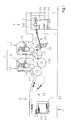
- the printing units 1.1 and 1.2 operate according to the wet offset method and accordingly each comprise an inking unit 1.3 and a dampening unit 1.4, a plate cylinder 1.5 in connection therewith, a blanket cylinder 1.6 operatively rolling on it and a printing cylinder 1.7 guiding a respective sheet.
- a sheet feeder 2 For feeding the printing units 1.1 and 1.2 with a sheet feeder 2 is provided which picks up a respective top sheet 2.2 by a stack 2.3 by means of a separating device 2.1 and transfers to a transport and alignment device 2.4, which leading each in the processing direction leading to an imbricated formation isolated sheet according to which in particular by means of a Saugb basicticians done transport in the direction of front edge stops on these and at least one side stop aligns.
- One of the first processing station here the printing unit 1.1, associated oscillating pre-gripper 1.8 accepts the respectively aligned sheet 2.2 and transfers it to a feed drum 1.9 which in turn passes it to the printing cylinder 1.7 of the printing unit 1.1.
- the printing cylinder 1.7 transfers the sheet 2.2 to a transfer device in the form of a sheet guiding drum 1.10, which is connected between the printing cylinders 1.7 of the two printing units 1.1 and 1.2 and which is discussed in detail elsewhere becomes.
- the printing cylinder 1.7 of the printing unit 1.2 accepts the sheet from the sheet guide drum 1.10, leads him through the other printing gap and then passes it to a, explained in more detail elsewhere transfer device comprising a operatively revolving endless conveyor, which the respective sheet 2.2 to a stacking station 3.1 transported and releases there to form a Druckgutstapels.
- the level of production at the stack 2.3 in the feeder 2 i. H. the height of the respective uppermost sheet 2.2, and in the stacking station 3.1, the drop height of the released sheet 2.2 by corresponding tracking respective stack 2.3 or the Druckgutstapel 3.2 supporting platforms 2.5 and 3.3 maintained by respective hoists, of which only the platforms 2.5 and 3.3 carrying lifting chains 2.6 and 3.4 are indicated.
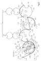
- exemplary reproduced constellation of printing cylinders and transfer devices substantially corresponds to in Fig. 1 illustrated conditions and represents two successive printing units 1.1 'and 1.2' of a machine section 1 ', wherein one of the transfer devices, the sheet 2.2 transported from one to the other of the printing cylinder 1.7.
- This transfer device comprises operationally in a first direction in accordance with the direction arrow 1.11 circumferential first gripper 1.12 holding the machine section 1 'fed sheet 2.2 to a leading in the processing direction gripper edge 2.2 "of the same, and the first gripper 1.12 bearing cylinder, here the impression cylinder 1.7, which forms on the circumference of a support surface 1.13 for the part of the first gripper detected sheet 2.2 ..
- the transfer device operatively in a for first opposite second direction according to the direction arrow 1.11 'circumferential second gripper 1.14. These pass through the first grippers 1.12 and take over from them the leading gripper edge 2.2 "of the sheet 2.2 It is understood that the second grippers 1.14 are formed contrary to the simplified graphic representation by means of gripper fingers and similarly as these encircling gripper finger supports.
- the transfer device comprises at least one pair - in the present embodiment with half-round rotating second grippers 1.14 according to Fig. 2 two pairs - in the second direction according to direction arrow 1.11 'about a rotation axis 1.15 rotating arches 1.16, each having a concentric to the rotation axis 1.15 rolling surface 1.17 whose extension along the axis of rotation 1.15 is smaller than the width of a respective non-pressure side edge of the sheet 2.2.
- a respective rolling surface 1.17 runs against the second grippers 1.14 and follows them.
- the extent of the rolling surfaces 1.17 in the circumferential direction substantially corresponds to the extension of the largest possible processable with the rotary printing machine sheet in the processing direction.
- the arch supports 1.16 are dimensioned and placed such that their rolling surfaces press a respective sheet 2.2 within its pressure-free side edges 2.2 'in areas of common normal of the rolling surfaces 1.17 and the support surface 1.13 to the latter while the leading gripper edge 2.2 "clamped holding second gripper 1.14 peel off the part 2.2 of the support surface 1.13 taken over by the first grippers 1.12 and wind it up on the rolling surfaces 1.17.
- the transfer device still operatively in the second direction according to directional arrow 1.11 'circumferential suction pads 1.18, which take a by means of the sheet supports 1.16 to the support surface 1.13 of the printing cylinder 1.7 applied trailing gripper edge 2.2'"of the sheet 2.2 from the impression cylinder 1.7
- Suction openings that open into a lying around the rolling surfaces 1.17 of the arch supports 1.16 envelope surface and they hurry the second grippers 1.14 in such a phase position that they pass the pressure cylinder 1.7 at a time in their operational circulation in which these suction openings the trailing gripper edge 2.2 '"face.
- the sheet 2.2 was already clamped at this time in the second gripper 1.14 and wound on the rolling surfaces 1.17 and from this time on the trailing gripper edge 2.2 '"of the sheet 2.2 is guided by means of the suction pads 1.18 additionally defined.
- the transfer of the device ultimately intended transfer of such a stabilized sheet to the printing cylinder 1.7 of the printing unit 1.2 'then takes place in such a way that the first grippers 1.12 on the printing cylinder 1.7 of the printing unit 1.1' corresponding first gripper 1.12 of the subsequent printing cylinder 1.7, the sheet 2.2 of the take over second grippers 1.14.
- the second gripper 1.14 represent the arch supports 1.16 and the suction pads 1.18 as components of the sheet guide drum 1.10.
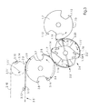
- Fig. 3 is a preferred use of the bow guide drum 1.10 equivalent sheet guide drum 3.6 reproduced, which here a Component of a transfer device for discharging the example, in the printing units 1.1 and 1.2 or 1.1 'and 1.2' processed sheet 2.2 represents.
- the sheet guiding drum is in this case a last sheet-guiding cylinder, downstream of the printing cylinder 1.7 of the printing unit 1.2 or 1.2 'in the present examples, and cooperates therewith in the manner set out in connection with the sheet guiding drum 1.10.
- the transfer device provided for discharging the processed sheets 2.2 further preferably comprises a transfer drum 3 .7 downstream of the sheet guiding drum 3. 1, operatively in the first direction (ie in the direction of rotation of the printing cylinder 1 .7), with third grippers 3. 8, which arrange the second one arranged here on the sheet guiding drum 3 Grapples 1.14 intermesh and pass from them the anticipatory gripper edge 2.2 '.
- the endless conveyor 3.5 ' comprises two chain pairs which are in each case operational in the second direction according to the directional arrow 1.11'.
- Each chain 3.10 of the chain pairs wraps around a deflecting body formed in particular in the form of a sprocket and one of four coaxial synchronously rotating sprockets 3.11, which are arranged in pairs at a mutual distance which is greater than that which can be processed in the largest possible in the machine section 1 or 1 ' bow present extent of the arc transverse to the processing direction.
- gripper bridges 3.12 supported by the chains 3.10 extend, on which pregrippers 3.13 for detecting the leading gripper edge 2.2 'are arranged.
- gripper bridges 3.14, carried by these chains 3.10 are arranged on which post grippers 3.15 for detecting the trailing gripper edge 2.2 '' are adjusted.
- the phase positions of the pregrippers 3.13 and the Nachgreifer 3.15 are adjusted so that the pregrippers 3.13 assume the leading gripper edge 2.2 "of the sheet 2.2 of the third grippers 3.8 and the grippers 3.15 the trailing gripper edge 2.2 '" of the sheet 2.2 of the suckers 3.9.
- Fig. 4 are shown in a spatial representation and simplified a sheet guiding drum and a transfer drum, the one another and on the one hand with the pressure cylinder 1.7 according to Fig. 3 and on the other hand with the endless conveyor 3.5 'according to Fig. 3 in terms of Fig. 3 explained way, so that in Fig. 4 the components that those of Fig. 3 correspond, are provided with the same reference numerals as in Fig. 3 , even in the case of constructive deviations that are irrelevant to the function. The same applies to the reference numerals in the Figures 2 and 3 ,
- Fig. 4 clarifies in particular the Figures 2 and 3 non-removable details that serve to adapt the transfer device to different formats of the sheet 2.2.
- drum shell transfer drum 3.7 according to the example of Figures 3 and 4 are provided for adjusting the phase position of the suction 3.9 in the drum shell surface circumferential grooves 3.16, along which the suckers 3.9 arranged therein are adjustable in a manner not shown.
- These circumferential grooves 3.16 have such a mutual distance, such a width and such a depth that arranged at a mutual distance along a respective gripper bridge 3.14 and take over the sheet 2.2 of the suction pads forming a suction 3.9 with these combing Nachgreifer 3.15 in this acquisition immerse each in the same circumferential groove in which a suction 3.9 is arranged.
- Said drum shell surface is preferably formed color repellent.
- the pregrippers 3.13 and the Nachgreifer 3.15 are preferably biased in a known manner by spring force in the closing direction and are opened in a known manner on Rollenhebelan kannen, which in turn are actuated by cams and, if necessary, with the pregrippers 3.13 or 3.15 with the Nachgreifern rotatably connected gripper shaft rotate in the sense of a gripper opening by a certain angle.
- the pre-gripper 3.13 and the Nachgreifer 3.15 go through in the embodiment according to Fig. 3 on one and the same surface lying tracks. However, this is not mandatory required.
- each of the two webs have common standards with an envelope drum enclosing the transfer drum 3.7 in the circumferential direction thereof and that, after gripping the trailing gripper edge 2.2 '' until a later release of the sheet 2.2, the distance of the pregripper leading to a bow 3.13
- An impermissible change in the distance would be, in particular, such an enlargement of the distance that the sheet 2.2 is pulled out of the pregrippers 3.13 or the picking grippers 3.15
- a permissible and preferably provided change in spacing exists, in particular, in a preferably temporary reduction of the distance Distance to the extent that the sheet 2.2 can form in a known manner a bead drawn into a nip of an unwinding device
- An intended unwinding device is preferably designed such that it excludes the gripper bars 3.12 and 3.14 A slack of the sheet 2.2 occurring in the region of a deflection of the endless conveyors 3.5 or 3.5 'is counteracted by means of blowing air.
- FIG. 4 is an example of a suitable design of the sheet guiding drum 3.6 removed, which in the same configuration, the Function of the sheet guiding drum 1.10 according to FIG Fig. 2 Fulfills.
- the sheet guide drum 3.6 comprises a drum core 3.17, to which - here only schematically indicated - the second gripper are arranged 1.14, which are also biased in a known manner in a closing direction and are opened on roller lever assemblies and these actuated cams as needed.
- the drum core 3.17 is provided in the present example with T-slots 3.18 extending in the longitudinal direction of the sheet guide drum 3.6 and record correspondingly T-shaped, provided on the arch supports 1.16 feet, which are clamped by means of clamping screws 3.19 in the T-slots 3.18.
- the drum core further has a recess 3.20, in which a suction device 3.21 with respect to the axis of rotation 3.22 of the sheet guiding drum 3.6 is arranged in a manner not shown pivotable and lockable.
- the suction device 3.21 forms a longitudinal direction of the sheet guiding drum 3.6, not shown, connected to a vacuum generator suction air duct 3.23.
- the suction grippers 1.18 have suction openings 1.18 'which communicate with the interior of the suction air shaft 3.23 and which open in the area between the sheet supports 1.16 into an enveloping surface spanned by the rolling surfaces 1.17.
- the suction pad 1.18 are preferably rigidly connected to the suction air shaft 2.23, while lying outside the smallest format suction pads 1.18 are so adjustable in the direction of the axis of rotation 3.22 out that a Adjustment of the arch supports 1.16 in the directions indicated by the double arrows 3.24 directions is possible to adjust the arch supports 1.16 on the pressure-free side edges 2.2 'of the sheet 2.2 can.
- the rolling surfaces 1.17 of the sheet guide drums 3.6 and 1.10 provided sheet supports 1.16 are preferably formed on a non-illustrated elastic coating of the sheet supports 1.16, wherein the coating has a hardness which is preferably about 50 Shore.
- the rolling surfaces are 1.17 formed on corresponding underlegbaren tread. This adaptation to larger differences in thickness of the sheet 2.2 is possible.
- the axis of rotation 3.22 of the sheet guiding drum 3.6 in the sense of the double arrow 3.25 (see FIG. 4 ) displaceable in order to press the rolling surfaces 1.17 under a sufficient pressing force against the side edges 2.2 'of the sheet 2.2 resting on the support surface 1.13.
- an in Fig. 2 illustrated transfer device for discharging the sheet 2.2 is provided, in which the sheets are transferred from the last processing station (here the printing unit 1.2 ') to an endless conveyor 3.5, which passes directly through the last processing station.
- This endless conveyor is constructed analogously to the already described endless conveyor 3.5 'and also includes two operatively in the second direction according to direction arrow 1.11' circulating chain pairs.
- each Chain 3.10 'of the chain pairs wraps around one of four operatively synchronously rotating same sprockets 3.11', which are analogous to the endless conveyor 3.5 'spaced apart and have a common axis of rotation 3.26.
- a first of these pairs of chains carries gripper bars 3.27, to which the second gripper designated here for the assumption of the leading gripper edge 2.2 'of the first grippers 1.12, here designated by 1.14' are arranged.
- the extension of the arch supports 1.16 'in the circumferential direction thereof is adjustable, namely to adapt to different extents of the processed sheet 2.2 in the processing direction.
- a leading arch support section is 1.16 " rotatably connected to a sprocket 3.28, which is rotatably connected to those sprockets 3.11 ', which is wrapped by the pair of chains, which carries the gripper bars 3.27 with the second grippers 1.14'.
- a trailing arch support section 1.16 '" is non-rotatably connected to a 3.36 concentric to the sprocket 3.28, which in turn is rotatably connected to those of the sprockets 3.11', which is looped by the pair of chains, which gripper 3.30 carries, on which trailing edge gripper 3.31 for gripping the trailing
- spoke-like arranged ribs are provided, with respect to which a respective arch support section 1.16 "and 1.16'.
- the adjustment along the sprocket shaft 3.28 takes place analogously to the arch supports 1.16 of the sheet guiding drum 3.6 according to FIG Fig. 4 along T-shaped guides.
- the phase position of the hollow shaft 3.29 is adjusted relative to the sprocket shaft 3.28 in the present case.
- FIGS. 2a to 2c For this purpose, suitable embodiments of the arch support sections 1.16 “and 1.16 '" shown.
- a first embodiment according to Fig. 2a Each of the two arch support sections 1.16 “and 1.16 '” with a rolling surfaces 1.17 forming rubber elastic tread 3.32 provided, which is fixedly arranged for example by vulcanization, so that the two treads 3.32 act in adjacent tracks of the side edges 2.2'.
- the arch support sections 1.16 "and 1.16 '" are laminated and they have a common tread 3.33 or 3.33' on.
- the winding device 3.34 up and unwound the winding device is preferably biased in terms of shortening the unwound tread 3.33 or 3.33' .
- the treads 3.33 and 3.33 ' preferably comprise a strain-resistant carrier tape.
- the treads 3.32 or 3.33 or 3.33 ' preferably have such an elasticity that they adapt to the most varied thicknesses of the processed sheet 2.2.
- the transferred transfer device for discharging the sheets 2.2 further comprises the downstream suction gripper 1.18 'which lifts the trailing gripper edge 2.2''from the support surface 1.13 of the printing cylinder 1.7 of the printing unit 1.2'
- the rear edge grippers 3.31 pass through the areas of common normal of the support surface 1.13 and the rolling surfaces 1.17 radially within the path traversed by the rolling surfaces 1.17 take over the trailing gripper edge 2.2 '"from the suction grippers 1.18 in the expiring gusset between the support surface 1.13 and the rolling surfaces 1.17. This is an already indicated difference in the design of the endless conveyor 3.5 to the endless conveyor 3.5 '.
Landscapes
- Feeding Of Articles By Means Other Than Belts Or Rollers (AREA)
- Discharge By Other Means (AREA)
Claims (9)
- Dispositif pour le transport d'une feuille destinée à une machine de traitement de feuille, en particulier une machine d'impression rotative, avec- des premiers organes de préhension (1.12) tournant fonctionnellement dans une première direction pour la préhension de la feuille à son bord allant dans la direction de traitement,- un cylindre (1.7) portant les premières organes de préhension (1.12) comprenant une surface d'appui (1.13) ménagée sur sa périphérie pour la feuille saisie du côté des premiers organes de préhension (1.12),- des seconds organes de préhension (1.14') tournant fonctionnellement dans une seconde direction opposée à la première direction, qui prennent en charge depuis premiers organes de préhension (1.12) le bord de préhension avant (2.2"), et- une paire unique de supports de feuilles (1.16, 1.16') vue dans la direction de l'axe de rotation qui tourne fonctionnellement dans la seconde direction autour de l'axe de rotation, les supports de feuille (1.16, 1.16') présentant une surface de roulement (1.17) concentrique avec l'axe de rotation, dont l'extension le long de l'axe de rotation est inférieure à la largeur d'un bord latéral respectif sans pression (2.2') de la feuille, et ne pressant la feuille contre la surface de support (1.13) qu'à l'intérieur du bord latéral respectif sans pression dans des zones de normales communes de la surface d'appui et des surfaces de roulement (1.13), caractérisé par
des ventouses de préhension (1.18) tournant fonctionnellement dans la seconde direction lesquelles prennent en charge depuis le cylindre (1.7) un bord de préhension (2.2"') de la feuille (2.2) arrière appliquée contre la surface d'appui (1.13) et un tambour guide-feuille (3.6) comprenant les seconds organes de préhension (1.14'), les supports de feuille (1.16) et les ventouses de préhension (1.18). - Dispositif selon la revendication 1,
caractérisé par- un tambour de transfert (3.7) rotatif fonctionnellement dans la première direction et placé en aval du tambour guide-feuille (3.6) avec des troisièmes organes de préhension (3.8) qui prennent en charge des deux seconds organes de préhension (1.14), le bord de préhension avant (2.2"), et des ventouses (3.9) suivant les troisièmes organes de préhension (3.8), qui prennent en charge, depuis les organes de préhension aspirants (1.18), le bord avant de préhension (2.2"') et- un convoyeur sans fin (3.5) comprenant des pré-organes de préhension tournant fonctionnellement et des post-organes de préhension (3.15), dont les pré-organes de préhension (3.13) prennent en charge depuis les organes de préhension (3.8) le bord de de préhension avant (2.2") et dont les post-organes de préhension (3.15) prennent en charge, depuis les ventouses (3.9), le bord arrière de préhension (2.2"'). - Dispositif selon la revendication 1,
caractérisé par
un convoyeur sans fin (3.5) tournant fonctionnellement, qui comprend les seconds organes de préhension (1.14') prévus pour la prise en charge du bord arrière de préhension (2.2"), depuis les premiers organes de préhension (1.12), et des organes de préhension de bords arrière (3.31), qui prennent en charge, depuis les organes de préhension ventouses (1.18), le bord de préhension (2.2"'). - Dispositif selon la revendication 3,
caractérisé en ce
que les organes de préhension de bord arrière (3.31) saisissent le bord arrière de préhension (2.2"') dans l'interstice de sortie entre la surface d'appui (1.13) et les surfaces de roulement (1.17). - Dispositif selon au moins l'une des revendications 1 à 4, caractérisé en ce
que la distance réciproque des supports de feuilles (1.16 ; 1.16') est réglable. - Dispositif selon au moins l'une des revendications 1 à 5, caractérisé en ce
que l'extension des surfaces de roulement (1.17) est réglable dans leur direction périphérique. - Dispositif selon au moins l'une des revendications 1 à 6, caractérisé en ce
que la position de phase des ventouses de préhension (1.18) est réglable. - Dispositif selon la revendication 2,
caractérisé en ce
que la position de phase des ventouses (3.9) est réglable. - Machine de traitement en particulier une machine d'impression rotative
caractérisée par
un dispositif pour le transport d'une feuille selon au moins l'une des revendications 1 à 8.
Applications Claiming Priority (2)
| Application Number | Priority Date | Filing Date | Title |
|---|---|---|---|
| DE10014417A DE10014417A1 (de) | 2000-03-24 | 2000-03-24 | Vorrichtung zum Transport eines Bogens für eine Rotationsdruckmaschine |
| DE10014417 | 2000-03-24 |
Publications (3)
| Publication Number | Publication Date |
|---|---|
| EP1136263A2 EP1136263A2 (fr) | 2001-09-26 |
| EP1136263A3 EP1136263A3 (fr) | 2005-08-10 |
| EP1136263B1 true EP1136263B1 (fr) | 2015-09-02 |
Family
ID=7636039
Family Applications (1)
| Application Number | Title | Priority Date | Filing Date |
|---|---|---|---|
| EP01103697.7A Revoked EP1136263B1 (fr) | 2000-03-24 | 2001-02-26 | Dispositif pour transporter une feuille pour une machine d'impression rotative |
Country Status (4)
| Country | Link |
|---|---|
| US (1) | US6578846B2 (fr) |
| EP (1) | EP1136263B1 (fr) |
| JP (1) | JP4657479B2 (fr) |
| DE (1) | DE10014417A1 (fr) |
Families Citing this family (45)
| Publication number | Priority date | Publication date | Assignee | Title |
|---|---|---|---|---|
| DE10164255A1 (de) * | 2001-12-27 | 2003-07-17 | Heidelberger Druckmasch Ag | Drei-Trommel-Wendeeinrichtung für bogenverarbeitende Maschine |
| DE10343428B4 (de) * | 2002-10-25 | 2021-02-25 | Heidelberger Druckmaschinen Ag | Bogen verarbeitende Rotationsdruckmaschine mit einem Nachgreifer aufweisenden Ausleger |
| DE50310965D1 (de) * | 2002-10-30 | 2009-02-05 | Heidelberger Druckmasch Ag | Bogentransporttrommel einer Bedruckstoffbogen verarbeitenden Maschine |
| DE10257497B4 (de) * | 2002-12-10 | 2008-02-21 | Koenig & Bauer Aktiengesellschaft | Bogenfördermodul und bogenverarbeitende Maschine |
| DE102004007599A1 (de) | 2003-03-27 | 2004-10-07 | Heidelberger Druckmaschinen Ag | Bogen verarbeitende Maschine mit einem Bogenentroller |
| JP4638165B2 (ja) | 2003-07-16 | 2011-02-23 | ハイデルベルガー ドルツクマシーネン アクチエンゲゼルシヤフト | 枚葉紙を処理する機械 |
| JP2005126234A (ja) | 2003-10-22 | 2005-05-19 | Heidelberger Druckmas Ag | 印刷技術機械を通して枚葉紙を搬送するための装置 |
| DE102004053099B4 (de) * | 2003-11-18 | 2016-12-22 | Heidelberger Druckmaschinen Ag | Verfahren zur Glättung eines Bogens aus Bedruckstoff |
| DE10358171A1 (de) * | 2003-12-12 | 2005-07-07 | Heidelberger Druckmaschinen Ag | Vorrichtung zum Fördern eines Bogens durch eine drucktechnische Maschine |
| DE102004009703A1 (de) * | 2004-02-27 | 2005-09-15 | Heidelberger Druckmaschinen Ag | Maschine zum Verarbeiten von Bogen aus Bedruckstoff |
| DE102005030813B4 (de) * | 2004-07-27 | 2013-10-31 | Heidelberger Druckmaschinen Ag | Maschine zum Verarbeiten eines Bogens aus Bedruckstoff |
| JP4709605B2 (ja) | 2004-07-27 | 2011-06-22 | ハイデルベルガー ドルツクマシーネン アクチエンゲゼルシヤフト | 被印刷体からなる枚葉紙を処理する機械 |
| US7448625B2 (en) | 2004-08-30 | 2008-11-11 | Heidelberger Druckmaschinen Ag | Apparatus for conveying a sheet through a printing machine with radially moving suction grippers |
| CN1847123B (zh) * | 2005-01-26 | 2010-04-14 | 海德堡印刷机械股份公司 | 具有用于分送出所选出的页张的装置的处理页张的机器 |
| US8302955B2 (en) * | 2005-06-17 | 2012-11-06 | Hewlett-Packard Development Company, L.P. | Rotating vacuum fingers for removal of printing media from an impression drum |
| DE102005050070A1 (de) * | 2005-10-19 | 2007-04-26 | Koenig & Bauer Ag | Bogenführender Rotationskörper |
| DE102006019029B4 (de) * | 2006-04-25 | 2013-10-17 | manroland sheetfed GmbH | Verarbeitungsmaschine für Bogenmaterial |
| EP1880846B1 (fr) * | 2006-07-18 | 2012-12-19 | Heidelberger Druckmaschinen AG | Presse offset à feuilles |
| JP5175079B2 (ja) | 2006-11-21 | 2013-04-03 | ハイデルベルガー ドルツクマシーネン アクチエンゲゼルシヤフト | 印刷技術的な機械を通ってシートを搬送するための装置 |
| DE102007051203B4 (de) | 2006-11-21 | 2020-01-23 | Heidelberger Druckmaschinen Ag | Vorrichtung zum Fördern eines Bogens durch eine drucktechnische Maschine |
| DE102007035435B4 (de) * | 2007-07-28 | 2009-04-16 | WINKLER+DüNNEBIER AG | Vorrichtung und Verfahren zum Einziehen von Flachmaterialstücken und registergenauen Transportieren der Flachmaterialstücke |
| DE102008014811B4 (de) | 2008-03-18 | 2017-03-09 | Koenig & Bauer Ag | Vorrichtung zum Fördern eines Bogens durch eine bogenverarbeitende Maschine |
| DE102008018314A1 (de) * | 2008-04-11 | 2009-10-15 | Koenig & Bauer Aktiengesellschaft | Bogendruckmaschine mit einem Ausleger, welcher mindestens zwei Bogenfördersysteme mit umlaufenden Fixierorganen enthält |
| DE102009000218B4 (de) | 2009-01-14 | 2020-01-23 | Koenig & Bauer Ag | Auslage einer bogenverarbeitenden Maschine mit einem Bogenfördersystem zum Übernehmen der Bogen von einem Bogenführungszylinder |
| DE102010003010B4 (de) * | 2010-03-18 | 2017-05-04 | manroland sheetfed GmbH | Vorrichtung zum Fördern eines Bogens in einem Bogenausleger einer Bogendruckmaschine |
| CN102189750B (zh) * | 2010-03-19 | 2015-02-18 | 海德堡印刷机械股份公司 | 用于输送页张通过印刷技术机器的装置 |
| JP5422458B2 (ja) * | 2010-03-25 | 2014-02-19 | 富士フイルム株式会社 | 媒体搬送装置及び画像形成装置並びに媒体搬送方法 |
| DE102013220059B4 (de) | 2012-10-05 | 2023-11-23 | Koenig & Bauer Ag | Auslagevorrichtung für eine bogenverarbeitende Maschine mit einem ersten Fördersystem für Bogenvorderkanten und einem zweiten Fördersystem für Bogenhinterkanten |
| DE102013220058B4 (de) | 2012-10-05 | 2023-11-23 | Koenig & Bauer Ag | Auslagevorrichtung für eine bogenverarbeitende Maschine mit einem ersten Fördersystem für Bogenvorderkanten und einem zweiten Fördersystem für Bogenhinterkanten und Verfahren zum Einstellen eines Greifersystems auf verschiedene Bogenformate |
| DE102013224489A1 (de) | 2012-12-04 | 2014-06-05 | Koenig & Bauer Ag | Bogenverarbeitende Maschine mit einer Bogentransporttrommel zum Umführen von Bogen und Verfahren zum Transport von Bogen |
| DE102013226315A1 (de) | 2012-12-21 | 2014-06-26 | Koenig & Bauer Aktiengesellschaft | Bogenverarbeitende Maschine mit einem Bearbeitungswerk und einer Auslage und Verfahren zum Betreiben einer bogenverarbeitenden Maschine |
| CN103600579B (zh) * | 2013-10-24 | 2017-01-04 | 沈阳达尔科技开发有限公司 | 用于印刷机中的空气流体式送纸装置 |
| DE102015204113A1 (de) | 2014-03-26 | 2015-10-01 | Koenig & Bauer Ag | Bogentransportvorrichtung für eine bogenverarbeitende Maschine und Verfahren zum Transportieren von Bogen von einem Bogenführungszylinder an ein Bogenfördersystem |
| DE102015226325B4 (de) | 2015-12-21 | 2019-06-13 | Koenig & Bauer Ag | Bogenverarbeitende Maschine mit einem einer Doppelgreiferauslage vorgeordneten Bogenführungszylinder und Verfahren zum Ablegen von Bogen |
| DE102015226327B4 (de) | 2015-12-21 | 2021-06-24 | Koenig & Bauer Ag | Bogenverarbeitende Maschine mit einem einer Doppelgreiferauslage vorgeordneten Bogenführungszylinder und Verfahren zum Ablegen von Bogen |
| DE102017218413A1 (de) | 2017-10-13 | 2019-04-18 | Koenig & Bauer Ag | Bogentransportvorrichtung und Verfahren zum Transportieren von Bogen von einem Bogenführungszylinder an ein Bogenfördersystem |
| DE102017218412A1 (de) | 2017-10-13 | 2019-04-18 | Koenig & Bauer Ag | Bogentransportvorrichtung und Verfahren zum Transportieren von Bogen von einem Bogenführungszylinder an ein Bogenfördersystem |
| DE102017218410B4 (de) | 2017-10-13 | 2021-06-17 | Koenig & Bauer Ag | Bogentransportvorrichtung und Verfahren zum Transportieren von Bogen von einem Bogenführungszylinder an ein Bogenfördersystem |
| EP3694719B1 (fr) * | 2017-10-13 | 2021-12-01 | Koenig & Bauer AG | Machine de traitement de feuilles dotée d'un dispositif de transport de feuilles, et procédé pour transporter des feuilles, d'un cylindre de guidage de feuilles à un système convoyeur de feuilles |
| DE102017012198B9 (de) | 2017-10-13 | 2022-10-06 | Koenig & Bauer Ag | Bogentransportvorrichtung und Verfahren zum Transportieren von Bogen von einem Bogenführungszylinder an ein Bogenfördersystem |
| DE102017218411B4 (de) | 2017-10-13 | 2021-06-10 | Koenig & Bauer Ag | Bogentransportvorrichtung und Verfahren zum Transportieren von Bogen von einem Bogenführungszylinder an ein Bogenfördersystem |
| EP3694718B1 (fr) * | 2017-10-13 | 2021-12-01 | Koenig & Bauer AG | Machine de traitement de feuilles dotée d'un dispositif de transport de feuilles et procédé de transport de feuilles d'un cylindre de guidage de feuilles vers un système de transport de feuilles |
| DE102017218407B4 (de) | 2017-10-13 | 2021-06-17 | Koenig & Bauer Ag | Bogentransportvorrichtung und Verfahren zum Transportieren von Bogen von einem Bogenführungszylinder an ein Bogenfördersystem |
| DE102017218409A1 (de) | 2017-10-13 | 2019-04-18 | Koenig & Bauer Ag | Bogentransportvorrichtung und Verfahren zum Transportieren von Bogen von einem Bogenführungszylinder an ein Bogenfördersystem |
| CN111315581B (zh) * | 2017-10-13 | 2022-03-11 | 柯尼格及包尔公开股份有限公司 | 加工单张纸的机器和用于由单张纸引导滚筒将单张纸传送给单张纸给送系统的方法 |
Citations (7)
| Publication number | Priority date | Publication date | Assignee | Title |
|---|---|---|---|---|
| DE220801C (fr) | ||||
| DE517004C (de) | 1930-01-23 | 1931-02-04 | Koenig & Bauer Schnellpressfab | Bogenausfuehrvorrichtung an Haltzylinderschnellpressen |
| DE629435C (de) | 1934-04-26 | 1936-05-05 | Alfred Winkler | Vorrichtung zum Ablegen und Anstapeln von? í¡? Werkstuecken |
| DE2621250B1 (de) | 1976-05-13 | 1977-03-17 | Heidelberger Druckmasch Ag | Bogenabfragevorrichtung in einer rotationsdruckmaschine |
| JPS5522953A (en) | 1978-08-08 | 1980-02-19 | Marubeni Harris Insatsu Kikai Kk | Device for sending printed paper out without damaging surface |
| JPS5518194Y2 (fr) * | 1975-07-03 | 1980-04-26 | ||
| DE4218421A1 (de) * | 1992-06-04 | 1993-12-09 | Heidelberger Druckmasch Ag | Bogenführung im Ausleger einer Druckmaschine |
Family Cites Families (10)
| Publication number | Priority date | Publication date | Assignee | Title |
|---|---|---|---|---|
| DE627851C (de) * | 1934-07-18 | 1936-03-25 | Maschf Augsburg Nuernberg Ag | Auslegevorrichtung fuer Bogendruckmaschinen |
| FR792636A (fr) | 1934-07-18 | 1936-01-07 | Maschf Augsburg Nuernberg Ag | Dispositif receveur à transport de feuille pour machines à imprimer par feuilles |
| US2757610A (en) * | 1952-03-18 | 1956-08-07 | Miller Printing Machinery Co | Sheet handling mechanism and method for multi-color perfector press |
| GB1230314A (fr) * | 1969-10-23 | 1971-04-28 | ||
| US4122773A (en) | 1974-04-24 | 1978-10-31 | Heidelberger Druckmaschinen Ag | Change-over means for a storage drum for sheet transferral |
| AR206823A1 (es) * | 1974-11-02 | 1976-08-23 | Heidelberger Druckmasch Ag | Tambor de traslacion en maquinas impresoras rotativas de pliegos |
| DE2832061A1 (de) * | 1978-07-21 | 1980-01-31 | Bosch Gmbh Robert | Durch einen gleichstrommotor ein- oder ausfahrbare teleskopantenne |
| DE3036790C2 (de) * | 1980-09-30 | 1982-11-11 | Heidelberger Druckmaschinen Ag, 6900 Heidelberg | Bogenübergabetrommel für auf Schön- und Widerdruck umstellbare Bogenrotationsdruckmaschinen |
| DE3535621A1 (de) * | 1985-10-05 | 1987-04-09 | Heidelberger Druckmasch Ag | Bogenuebergabetrommel |
| JP2898529B2 (ja) * | 1993-12-02 | 1999-06-02 | 株式会社桜井グラフィックシステムズ | 枚葉印刷機の枚葉紙反転機構 |
-
2000
- 2000-03-24 DE DE10014417A patent/DE10014417A1/de not_active Ceased
-
2001
- 2001-02-26 EP EP01103697.7A patent/EP1136263B1/fr not_active Revoked
- 2001-03-26 JP JP2001087826A patent/JP4657479B2/ja not_active Expired - Fee Related
- 2001-03-26 US US09/817,577 patent/US6578846B2/en not_active Expired - Lifetime
Patent Citations (7)
| Publication number | Priority date | Publication date | Assignee | Title |
|---|---|---|---|---|
| DE220801C (fr) | ||||
| DE517004C (de) | 1930-01-23 | 1931-02-04 | Koenig & Bauer Schnellpressfab | Bogenausfuehrvorrichtung an Haltzylinderschnellpressen |
| DE629435C (de) | 1934-04-26 | 1936-05-05 | Alfred Winkler | Vorrichtung zum Ablegen und Anstapeln von? í¡? Werkstuecken |
| JPS5518194Y2 (fr) * | 1975-07-03 | 1980-04-26 | ||
| DE2621250B1 (de) | 1976-05-13 | 1977-03-17 | Heidelberger Druckmasch Ag | Bogenabfragevorrichtung in einer rotationsdruckmaschine |
| JPS5522953A (en) | 1978-08-08 | 1980-02-19 | Marubeni Harris Insatsu Kikai Kk | Device for sending printed paper out without damaging surface |
| DE4218421A1 (de) * | 1992-06-04 | 1993-12-09 | Heidelberger Druckmasch Ag | Bogenführung im Ausleger einer Druckmaschine |
Also Published As
| Publication number | Publication date |
|---|---|
| JP2001270079A (ja) | 2001-10-02 |
| EP1136263A2 (fr) | 2001-09-26 |
| DE10014417A1 (de) | 2001-09-27 |
| EP1136263A3 (fr) | 2005-08-10 |
| US20020135123A1 (en) | 2002-09-26 |
| US6578846B2 (en) | 2003-06-17 |
| JP4657479B2 (ja) | 2011-03-23 |
Similar Documents
| Publication | Publication Date | Title |
|---|---|---|
| EP1136263B1 (fr) | Dispositif pour transporter une feuille pour une machine d'impression rotative | |
| DE3413159C2 (de) | Bogen-Rotations-Offsetdruckmaschine zur Herstellung von einseitigen Mehrfarbendruck oder Schön- und Widerdruck | |
| EP0161522B1 (fr) | Machine à imprimer rotative à feuilles pour impression polychrome unilatérale ou impression recto-verso | |
| EP0769376B1 (fr) | Machine d'impression de feuilles | |
| DE3710257C2 (fr) | ||
| DE19835003A1 (de) | Ausleger für eine Druckmaschine | |
| DE2724621A1 (de) | Bogenwendevorrichtung einer bogen- rotations-druckmaschine in reihenbauart | |
| EP1132324B1 (fr) | Entraínement par courroie pour une machine de traitement de matériaux imprimés plats | |
| DE102005012527A1 (de) | Anlegeeinheit für eine Bogenverarbeitungsmaschine, Bogenverarbeitungsmaschine und Verfahren zum Anlegen von Bogen | |
| DE102004007599A1 (de) | Bogen verarbeitende Maschine mit einem Bogenentroller | |
| EP0158129B1 (fr) | Rotative pour feuilles pour imprimer à retiration ou en plusieurs couleurs | |
| DE3114581C2 (de) | Fördervorrichtung für eine Bogen-Rotationsdruckmaschine | |
| DE102015226325B4 (de) | Bogenverarbeitende Maschine mit einem einer Doppelgreiferauslage vorgeordneten Bogenführungszylinder und Verfahren zum Ablegen von Bogen | |
| EP0241663B1 (fr) | Dispositif pour convoyer et tourner des feuilles pour machines traitant des feuilles | |
| DE102015226328A1 (de) | Auslage für eine bogenverarbeitende Maschine und Verfahren zum Ablegen von Bogen | |
| EP0968821A2 (fr) | Cylindre à transport des feuilles dans une presse à feuilles rotative | |
| DE4220011C2 (de) | Verfahren und Einrichtung zum automatischen Ein- und/oder Auszug von flexiblen Druckplatten | |
| DE102015226327B4 (de) | Bogenverarbeitende Maschine mit einem einer Doppelgreiferauslage vorgeordneten Bogenführungszylinder und Verfahren zum Ablegen von Bogen | |
| DE3444849C2 (fr) | ||
| DE19720742A1 (de) | Einrichtung in Bogenauslegern | |
| DE102017207052B4 (de) | Vorrichtung zum Aufziehen eines Aufzuges auf einem Druckwerkszylinder eines Druckwerks und Vorrichtung zum Wechseln eines Aufzuges an einem Druckwerkzylinder | |
| DE10211007A1 (de) | Vorrichtung zum Unterfangen von Bogen | |
| EP3615338B1 (fr) | Unité d'impression prévue pour imprimer des supports d'impression en feuille, machine pour impression sur métaux avec une telle unité d'impression et procédé de montage d'ascenseurs dans les cylindres d'une unité d'impression pour imprimante sur feuilles | |
| DE102008014811B4 (de) | Vorrichtung zum Fördern eines Bogens durch eine bogenverarbeitende Maschine | |
| DE102015226332B4 (de) | Auslage für eine bogenverarbeitende Maschine und Verfahren zum Ablegen von Bogen |
Legal Events
| Date | Code | Title | Description |
|---|---|---|---|
| PUAI | Public reference made under article 153(3) epc to a published international application that has entered the european phase |
Free format text: ORIGINAL CODE: 0009012 |
|
| AK | Designated contracting states |
Kind code of ref document: A2 Designated state(s): AT BE CH CY DE DK ES FI FR GB GR IE IT LI LU MC NL PT SE TR |
|
| AX | Request for extension of the european patent |
Free format text: AL;LT;LV;MK;RO;SI |
|
| PUAL | Search report despatched |
Free format text: ORIGINAL CODE: 0009013 |
|
| AK | Designated contracting states |
Kind code of ref document: A3 Designated state(s): AT BE CH CY DE DK ES FI FR GB GR IE IT LI LU MC NL PT SE TR |
|
| AX | Request for extension of the european patent |
Extension state: AL LT LV MK RO SI |
|
| 17P | Request for examination filed |
Effective date: 20050906 |
|
| AKX | Designation fees paid |
Designated state(s): AT BE CH CY DE DK ES FI FR GB GR IE IT LI LU MC NL PT SE TR |
|
| GRAP | Despatch of communication of intention to grant a patent |
Free format text: ORIGINAL CODE: EPIDOSNIGR1 |
|
| INTG | Intention to grant announced |
Effective date: 20150422 |
|
| RIN1 | Information on inventor provided before grant (corrected) |
Inventor name: MAUL, ALBERT Inventor name: RAUTERT, JUERGEN |
|
| GRAS | Grant fee paid |
Free format text: ORIGINAL CODE: EPIDOSNIGR3 |
|
| GRAA | (expected) grant |
Free format text: ORIGINAL CODE: 0009210 |
|
| AK | Designated contracting states |
Kind code of ref document: B1 Designated state(s): AT BE CH CY DE DK ES FI FR GB GR IE IT LI LU MC NL PT SE TR |
|
| REG | Reference to a national code |
Ref country code: GB Ref legal event code: FG4D Free format text: NOT ENGLISH |
|
| REG | Reference to a national code |
Ref country code: AT Ref legal event code: REF Ref document number: 746299 Country of ref document: AT Kind code of ref document: T Effective date: 20150915 Ref country code: CH Ref legal event code: EP |
|
| REG | Reference to a national code |
Ref country code: IE Ref legal event code: FG4D Free format text: LANGUAGE OF EP DOCUMENT: GERMAN |
|
| REG | Reference to a national code |
Ref country code: DE Ref legal event code: R096 Ref document number: 50116498 Country of ref document: DE |
|
| PG25 | Lapsed in a contracting state [announced via postgrant information from national office to epo] |
Ref country code: FI Free format text: LAPSE BECAUSE OF FAILURE TO SUBMIT A TRANSLATION OF THE DESCRIPTION OR TO PAY THE FEE WITHIN THE PRESCRIBED TIME-LIMIT Effective date: 20150902 Ref country code: GR Free format text: LAPSE BECAUSE OF FAILURE TO SUBMIT A TRANSLATION OF THE DESCRIPTION OR TO PAY THE FEE WITHIN THE PRESCRIBED TIME-LIMIT Effective date: 20151203 |
|
| REG | Reference to a national code |
Ref country code: NL Ref legal event code: MP Effective date: 20150902 |
|
| PG25 | Lapsed in a contracting state [announced via postgrant information from national office to epo] |
Ref country code: SE Free format text: LAPSE BECAUSE OF FAILURE TO SUBMIT A TRANSLATION OF THE DESCRIPTION OR TO PAY THE FEE WITHIN THE PRESCRIBED TIME-LIMIT Effective date: 20150902 Ref country code: ES Free format text: LAPSE BECAUSE OF FAILURE TO SUBMIT A TRANSLATION OF THE DESCRIPTION OR TO PAY THE FEE WITHIN THE PRESCRIBED TIME-LIMIT Effective date: 20150902 |
|
| PG25 | Lapsed in a contracting state [announced via postgrant information from national office to epo] |
Ref country code: NL Free format text: LAPSE BECAUSE OF FAILURE TO SUBMIT A TRANSLATION OF THE DESCRIPTION OR TO PAY THE FEE WITHIN THE PRESCRIBED TIME-LIMIT Effective date: 20150902 Ref country code: IT Free format text: LAPSE BECAUSE OF FAILURE TO SUBMIT A TRANSLATION OF THE DESCRIPTION OR TO PAY THE FEE WITHIN THE PRESCRIBED TIME-LIMIT Effective date: 20150902 |
|
| PG25 | Lapsed in a contracting state [announced via postgrant information from national office to epo] |
Ref country code: PT Free format text: LAPSE BECAUSE OF FAILURE TO SUBMIT A TRANSLATION OF THE DESCRIPTION OR TO PAY THE FEE WITHIN THE PRESCRIBED TIME-LIMIT Effective date: 20160104 Ref country code: BE Free format text: LAPSE BECAUSE OF NON-PAYMENT OF DUE FEES Effective date: 20160229 |
|
| REG | Reference to a national code |
Ref country code: DE Ref legal event code: R026 Ref document number: 50116498 Country of ref document: DE |
|
| PLBI | Opposition filed |
Free format text: ORIGINAL CODE: 0009260 |
|
| 26 | Opposition filed |
Opponent name: KOENIG & BAUER AG Effective date: 20160601 |
|
| PLAX | Notice of opposition and request to file observation + time limit sent |
Free format text: ORIGINAL CODE: EPIDOSNOBS2 |
|
| PLBB | Reply of patent proprietor to notice(s) of opposition received |
Free format text: ORIGINAL CODE: EPIDOSNOBS3 |
|
| PG25 | Lapsed in a contracting state [announced via postgrant information from national office to epo] |
Ref country code: DK Free format text: LAPSE BECAUSE OF FAILURE TO SUBMIT A TRANSLATION OF THE DESCRIPTION OR TO PAY THE FEE WITHIN THE PRESCRIBED TIME-LIMIT Effective date: 20150902 |
|
| PG25 | Lapsed in a contracting state [announced via postgrant information from national office to epo] |
Ref country code: MC Free format text: LAPSE BECAUSE OF FAILURE TO SUBMIT A TRANSLATION OF THE DESCRIPTION OR TO PAY THE FEE WITHIN THE PRESCRIBED TIME-LIMIT Effective date: 20150902 Ref country code: LU Free format text: LAPSE BECAUSE OF FAILURE TO SUBMIT A TRANSLATION OF THE DESCRIPTION OR TO PAY THE FEE WITHIN THE PRESCRIBED TIME-LIMIT Effective date: 20160226 |
|
| REG | Reference to a national code |
Ref country code: CH Ref legal event code: PL |
|
| GBPC | Gb: european patent ceased through non-payment of renewal fee |
Effective date: 20160226 |
|
| PG25 | Lapsed in a contracting state [announced via postgrant information from national office to epo] |
Ref country code: CH Free format text: LAPSE BECAUSE OF NON-PAYMENT OF DUE FEES Effective date: 20160229 Ref country code: LI Free format text: LAPSE BECAUSE OF NON-PAYMENT OF DUE FEES Effective date: 20160229 |
|
| REG | Reference to a national code |
Ref country code: FR Ref legal event code: ST Effective date: 20161028 |
|
| REG | Reference to a national code |
Ref country code: IE Ref legal event code: MM4A |
|
| PG25 | Lapsed in a contracting state [announced via postgrant information from national office to epo] |
Ref country code: IE Free format text: LAPSE BECAUSE OF NON-PAYMENT OF DUE FEES Effective date: 20160226 Ref country code: GB Free format text: LAPSE BECAUSE OF NON-PAYMENT OF DUE FEES Effective date: 20160226 Ref country code: FR Free format text: LAPSE BECAUSE OF NON-PAYMENT OF DUE FEES Effective date: 20160229 |
|
| REG | Reference to a national code |
Ref country code: AT Ref legal event code: MM01 Ref document number: 746299 Country of ref document: AT Kind code of ref document: T Effective date: 20160226 |
|
| PGFP | Annual fee paid to national office [announced via postgrant information from national office to epo] |
Ref country code: DE Payment date: 20170228 Year of fee payment: 17 |
|
| PG25 | Lapsed in a contracting state [announced via postgrant information from national office to epo] |
Ref country code: AT Free format text: LAPSE BECAUSE OF NON-PAYMENT OF DUE FEES Effective date: 20160226 |
|
| REG | Reference to a national code |
Ref country code: DE Ref legal event code: R064 Ref document number: 50116498 Country of ref document: DE Ref country code: DE Ref legal event code: R103 Ref document number: 50116498 Country of ref document: DE |
|
| RDAF | Communication despatched that patent is revoked |
Free format text: ORIGINAL CODE: EPIDOSNREV1 |
|
| STAA | Information on the status of an ep patent application or granted ep patent |
Free format text: STATUS: THE PATENT HAS BEEN GRANTED |
|
| RDAG | Patent revoked |
Free format text: ORIGINAL CODE: 0009271 |
|
| STAA | Information on the status of an ep patent application or granted ep patent |
Free format text: STATUS: PATENT REVOKED |
|
| 27W | Patent revoked |
Effective date: 20171025 |
|
| REG | Reference to a national code |
Ref country code: AT Ref legal event code: MA03 Ref document number: 746299 Country of ref document: AT Kind code of ref document: T Effective date: 20171025 |
|
| PG25 | Lapsed in a contracting state [announced via postgrant information from national office to epo] |
Ref country code: CY Free format text: LAPSE BECAUSE OF FAILURE TO SUBMIT A TRANSLATION OF THE DESCRIPTION OR TO PAY THE FEE WITHIN THE PRESCRIBED TIME-LIMIT Effective date: 20150902 |
|
| PG25 | Lapsed in a contracting state [announced via postgrant information from national office to epo] |
Ref country code: TR Free format text: LAPSE BECAUSE OF FAILURE TO SUBMIT A TRANSLATION OF THE DESCRIPTION OR TO PAY THE FEE WITHIN THE PRESCRIBED TIME-LIMIT Effective date: 20150902 |