EP1112149B1 - Einhandbetätigbare, sich selbst zustellende zange - Google Patents
Einhandbetätigbare, sich selbst zustellende zange Download PDFInfo
- Publication number
- EP1112149B1 EP1112149B1 EP99946136A EP99946136A EP1112149B1 EP 1112149 B1 EP1112149 B1 EP 1112149B1 EP 99946136 A EP99946136 A EP 99946136A EP 99946136 A EP99946136 A EP 99946136A EP 1112149 B1 EP1112149 B1 EP 1112149B1
- Authority
- EP
- European Patent Office
- Prior art keywords
- pliers
- spring
- section
- limb
- bow
- Prior art date
- Legal status (The legal status is an assumption and is not a legal conclusion. Google has not performed a legal analysis and makes no representation as to the accuracy of the status listed.)
- Expired - Lifetime
Links
Images


Classifications
-
- B—PERFORMING OPERATIONS; TRANSPORTING
- B25—HAND TOOLS; PORTABLE POWER-DRIVEN TOOLS; MANIPULATORS
- B25B—TOOLS OR BENCH DEVICES NOT OTHERWISE PROVIDED FOR, FOR FASTENING, CONNECTING, DISENGAGING OR HOLDING
- B25B7/00—Pliers; Other hand-held gripping tools with jaws on pivoted limbs; Details applicable generally to pivoted-limb hand tools
- B25B7/06—Joints
- B25B7/10—Joints with adjustable fulcrum
Definitions
- the invention relates to a one-hand operated, self-adjusting pliers according to the features of the preamble of claim 1.
- the invention deals with the task of one self-tongs in a simple advantageous embodiment specify.
- the spring drive consists of a spring supported on both pliers legs, so is designed that both a The jaws are spaced apart, as well as a method of moving the pliers leg in the largest mouth opening position, while rotating the Pliers leg is caused by this spring, being at least on one side a rotating support of the spring is formed on the pliers leg and the spring this side in the actuated state against one on the Pliers limb trained rotary stop, when moving the movable pliers leg in a jaw closing position that grips a workpiece Spring only after power is applied when the jaws of the pliers are in contact on the workpiece from the rotary stop comes. This results in a self-contained power system, integrated into a control.
- the feather is so biased that the movable pliers leg with the pliers released into the open position fast.
- the control is supported by a pair of pliers legs Spring is formed, which at the same time the pliers mouth preloads the open position.
- the rotation stop is designed as a supporting flank. This can be done technically easy to take into account.
- Provided at one Leg spring are two spring sections, that are differently rigid. That yields a working order of the spring drive. Brings further the invention in proposal that the different Rigidity due to a different length of the spring sections is achieved.
- the Spring into the two spring sections by means of one Spring winding is divided.
- Such a multi-layer executable spring turn contains a customized stored Spring force reserve.
- the spring articulation points differently close to that Pliers mouth are arranged. Specifically, it looks like that the pivot point of the longer spring section closer is on the pliers mouth.
- the shorter spring section is supported against the pliers mouth not exceedable. Provisions have been made that a Rotational mobility of the short spring section in the Articulation point is limited in angle. It is intended here that the angle of rotation is an acute angle. Is further provided that the spring two turns side by side having. This results in an even more balanced one Force system, especially a good spring characteristic.
- the rigid section is like the short section of spring, going against the pliers mouth supported not exceedable. It is still proposed that the spring section is formed by a spiral spring. It can be here even dealing with a leaf spring with a central one non-circular cross-section of slip-free end turn. It is advantageous that the rigid section is a handlebar, at one end the spring element is attached in the manner described and its other end rotatably arranged on the pliers leg is, again here with the proviso that it cannot be exceeded Support.
- the handlebar is formed in pairs and by spacing the two Handlebars a space for the spring and the spring attachment leaves. It is advantageous that the Spring attachment by a winding package Passing spring turn, connecting the handlebars Trunnion is achieved. The spring is tied up so securely. It is also favorable that the rigid section facing spring section as a torsion spring trained spring itself on the rigid section supported. The support can be cut free Tongue of the handlebar; alternatively can the support of one that also connects the handlebars Be formed cones. Then in proposal brought that spring to two knee-like together connected rigid sections is supported.
- a pair of pliers with a minimum of components is achieved if the spring as a bow spring with bow arms and a bracket turn is formed, the bracket arms on one of the pliers legs and the stirrups another of the pliers legs is supported.
- spring and Control elements are designed integrally.
- the bow arms or the stirrups are one on one Pliers legs supported on a rotatably mounted rigid section.
- the spring preload of the spring drive as well the spring force itself is thereby applied that the cantilever arms on a rigid section or a pliers leg over different axes of rotation are rotatably supported.
- the distance between the axes of rotation is aimed at pivoting the pliers legs Implemented spring force.
- the bow arms are different long trained.
- the bow arms can be curved Show course, for example in the sense of an already easy Precurvature.
- the curvature faces the forceps mouth concave.
- the loop turn is helical.
- the bearing eye is not claimed in the sense of a torsion effect.
- the loop turn on a pliers leg is supported for longitudinal movement. A simple assignment is achieved in that the stirrups in an elongated hole in a pair of pliers is included.
- the support the stirrup is profiled with one inclined to the longitudinal direction of the pliers leg and the initial support surface that traps the bend.
- An alternative feature is that at the Stirrups a one acting in the longitudinal direction of the pliers legs Tension spring attacks.
- the pliers 1 of all exemplary embodiments have two intersecting pliers legs 2 and 3. The latter are in the crossing area via a hinge pin 4 articulated against each other.
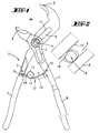
- the hinge pin 4 passes through a longitudinal slot 9 of the Pliers leg 2.
- the hinge pin 4 is mounted in the penetrated pliers legs 3.
- the hinge pin 4 carries a pawl 10. This acts with tooth gaps 11 on the mouth side horizontal tooth profile of the penetrating Pliers legs 2 together.
- Fig. 2 shows that in Fig. 1st present release position, FIG. 6 that in FIG. 5 engaged latching position of this locking toothing.
- Longitudinal slot 9 and tooth gaps 11 can instead of the penetrating Pliers legs 3 formed his.
- the penetrated leg of the pliers corresponds 3 geometrically the pliers leg 2 in the attached drawing, only with the difference that these pliers legs then two across the longitudinal plane of the pliers spaced and provided with tooth gaps 11 slots having.
- the penetrating pliers leg geometrically otherwise according to the pliers leg 2 trained according to the attached drawing, recorded.
- the pliers 1 is open-mouthed via a spring drive 12 Basic position held (see Fig. 1, 11, 17, 18, 19, 20, 22, 24, 26). To do this, it works in the space between Pliers legs 2, 3 accommodated spring drive 12 spreading pliers legs.
- the end position is defined by Stop at the lower end of the slot-like longitudinal slot 9th
- the spring drive 12 has a preload as a dash-dotted position in Fig. 1. Insofar the opening position is effective, but preloaded so that it can be overcome. Closing the spread pliers legs 2, 3 moves the jaw 6 of the sliding and pivotable pliers leg 3 in the direction the pliers jaw 5 of the penetrating pliers leg 2. This can be seen from Fig. 3. The open position 1 is accordingly understandable after relieving the grip sections 7, 8 of the pliers legs 2, 3 completely automatically by the described Spring-loaded.
- the cross the gusset area of the pliers legs 2, 3 or bridging spring drive 12 also takes over Function of a control element 13. That protrudes, is supported from the penetrating pliers leg 2, on the gusset side freestanding. It forms a kind of cantilever, whereby in a first movement section of the spring drive 12 Forceps jaws 5, 6 to drive one another and in a second movement section an engagement of the pawl 10 of the hinge pin 4 in the locking teeth 11 he follows. After this, a force twist of the movable, thus penetrated pliers legs 3 or his Forceps jaw 6, going around the hinge pin 4, can be carried out. Overlapping movements take place here.
- the spring drive / control element 12/13 provides the first two embodiments, a spring 14, more precisely a leg spring.
- the ends of the spring 14 are each on one of the Pliers legs 2, 3 articulated.
- the articulation point on enforced pliers legs 3 is designated 15. It is a pivot point.
- the most assertive Pliers leg 2 is the articulation point 16.
- the geometric axes of the articulation points 15, 16 are parallel to the geometric axis of the hinge pin 4th
- the spring 14 or leg spring has two spring sections different effective stiffness.
- the a spring section a is the more spring-friendly.
- the other spring section b His Resilience can even go to zero. This Spring section b is assigned to the pliers leg 2.
- the different resilience is based on different Lengths of the spring sections a, b made of wire, regardless of whether one of the spring sections is still in there is a (further) turn 17 such as that Embodiment of FIG. 11
- the two are more stretched or curved Spring sections a, b assume a common spring turn 17 out. It lies on the hinge pin 4 facing side of the spring 14.
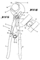
- the spring articulation points 15, 16 are different arranged close to the pliers mouth M. So lies the articulation point 15 of the longer spring section a Forceps M closer. The approaching becomes even clearer with closed pliers 1 or with object handle.
- the corresponding Object for example a pipe, is designated 18 (see e.g. Fig. 5).
- the leg spring springs out with respect to the spring turn 17 on the handle section side.
- the articulation points 15, 16 and the end supported position the hinge pin 4 form an inherently stable hinge triangle, caused by the restoring force of the preloaded Spring 14.
- the shorter spring section b is on the handle leg side supported.
- the support flank as a turning stop bears the reference number 19. It is such that the shorter spring section b only faces away from the pivot pin can pivot about its hinge point 16. From the support surface 19 goes one the end section close to the joint of the shorter spring section 9 securing nose 20.
- the rotational mobility of the shorter spring section b is also limited in angle. It is a acute-angled free range of motion.
- the top The angle includes about 30 to 40 °.
- the one that forms the longer spring section a The end is rolled into a bearing eye 22 at the end. The other end forms an angled bearing journal 23rd
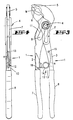
- the spring drive 12 is according to the second embodiment basically the same structure.
- the reference numbers are transferred analogously, without repeated text.
- the difference is that the spring 14 two Spring turns 17 provides. They are close together so that in principle there is an eight. They too selected there with respect to the shorter spring section b Support surface is designated 19. It stretches now instead of across, in the longitudinal direction of the penetrating Pliers legs 2.
- the shorter spring section b now strictly stretched, whereas he has an obtuse angle according to the first embodiment Kink shows. It is predetermined and can be found when it hits on the stop edge 21 even more concise train, so be included in the suspension.
- the control element 12 is there from a spring section a and a rigid section b '. In a figurative sense, this shorter spring section forms now a practically non-resilient element.
- the spring section a is the outer end section of a Spiral spring 25. It takes a slightly arched, seen from the handle sections 7, 8 convex Course and passes into the bearing eye 22. The inner one End turn of the spiral spring 25 is on the rigid section b ' attached. The fixing is on a square 26 performed. The protrudes transversely from a handlebar 27.
- the Handlebar 27 can be formed in pairs, such that the wound section of the spiral spring 25 is covered, thus, as it were, receives a spring chamber.
- the square 26 is fixed to the handlebar (s) 27 connected.
- the other end of the handlebar 27 is rotatable articulated on the penetrating pliers leg 2, also here forming the articulation point 16.
- This too Embodiment includes the provision that the shorter section of the spring drive 12, here the Rigid section b ', not going against the jaw M is supported by the Support flank 19 of the pliers leg 2 shown.
- the spring is thus advantageously used that they also function as an actuator (Control element 13) takes over.
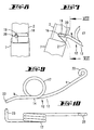
- Control element 13 can Feathers - as indicated - also in the form of a leaf spring be realized as the fourth according to FIG. 17 Embodiment is also apparent.
- With empty Closing the mouth M essentially only springs the one, longer spring section a using a stored in the form of turns 17 (see also FIG. 18) Spring force reserve.
- the shorter section of the spring practically remains in its through a support flank given basic position.
- becomes a gripping object gripped by the mouth M of the pliers 1 so takes place in a kind of reverse thrust over the longer spring section a a pivoting of the shorter spring section b instead, be it that it also springs or is rigid.
- the course of the spring 14 is also an S-shaped course conceivable (see FIG. 18), with the S-web the spring turn 17 has.
- the longer spring section is a aligned as shown in the exemplary embodiments, whereas the shorter spring section b is a U-turn 28 takes in the direction of the pivot pin 4.
- This Spring section is a little longer and also spring joyful.
- the winding cavities can be in all Embodiments by push-button connectable Plates or buttons must be closed.
- the fifth embodiment shown in FIG. 19 the pliers 1 is the pliers according to the third embodiment structurally close, the control element 13 from a combination spring section a and Rigid section b '.
- the one provided here Rotary stop in the form of a support flank 19 secures the Fold-out folding movement of the spring drive 12.
- the Reference numbers are used analogously, in part without repeated text.
- the Spring section b not continuously to the articulation point 16 trained; rather, it is within the open space the pair of links 27 supported.
- the Spring section b occurs against a pin 30, which is spaced from the support pin 29 the spring chamber formative free space.
- the ends of the cones 29 and 30 are in the plate-shaped parts of the handlebar 27 attached.
- Such a torsion spring is also the sixth Embodiment used. It is on the figures 20 and 21 referenced.
- This spring 14 is knee-like interconnected rigid sections b 'assigned. The knee joint there bears the reference symbol 31. The mutually pointing ends of the two rigid sections b 'are via articulation points 15, 16 with the Pliers legs 2, 3 articulated. The buckling direction the knee joint is also facing away from the mouth.
- the two rigid sections b ' are of nested U-profile sections formed. In the area of the knee joint 31 is on a stop-forming Attention overlap of the ends there. The results in a defined, caused by the spring 14 Stretching position of the two rigid sections b '. This one both spring sections labeled a act accordingly in the direction facing away from the mouth Rigid sections b '.
- the pliers legs 2, 3 or their grip sections 7, 8 spreading spring drive 13 is still here by another arranged on the handle section 8
- Spring 32 supports Accordingly, it works in the same direction with regard to the stretched position of the rigid section b 'to each other, which are so well biased.
- the stretched position is that the two Rigid sections in the stretched state between them an opening angle of less than 180 ° on the mouth side lock in.
- the knee pivot 31 can not in one Dead center position between the articulation points 15 and 16 occur. All other spring drives 12 can only face away from the mouth buckle, e.g. because of the handle section accordingly Curvature or an angular course of rigid section b 'and spring section a.
- the further spring 32 is with one over the articulation point 15 outgoing rigid section b '' connected.
- This rigid section b '' gives the rigid section b ' a double-armed figure.
- the spring 32 is a tension spring. In return, the shorter arm of the double-armed could Rigid section b '/ b' 'there also as a compression spring attack.
- the spring 32 expediently comes in the free space F of the pliers leg 3 under.
- the pliers 1 according to the seventh embodiment has a bow spring B as the spring 14 on. It has two bracket arms 33, 33 '. The one as it were closed U forming bow spring B has a relative briefly designed bow turn 33 ''. The bow arms 33, 33 'are of different lengths. The one labeled 33 is the shorter arm. assessment basis is the bend that lies across the bracket arms 33 ".
- the bow spring B provides the spring drive 12 at the same time the handlebar-like control element 13.
- the latter is with respect to a plane of symmetry of the pliers 1 inclined.
- the bracket arms 33, 33 'on the pliers leg designated by 3 forming joints supported.
- the bow turn is 33 '' supported on the pliers legs designated by 2.
- the joint point on the pliers leg 3 has two digits.
- the articulation point for the shorter arm 33 bears the reference numeral 15 'that of the longer bracket arm 33 'the symbol 15' '.
- the latter articulation point is located maul closer.
- This control element 13 is as a hairpin U-shaped.
- the bow turn 33 "acts as a torsion spring bar.
- the bow turn 33 '' is supported on the pliers leg 2 and guided longitudinally. It crosses an elongated hole 34 of the pliers leg 2 and is included.
- the Slot 34 is of such a length that when biting the pliers 1 the corresponding evasive movement can be carried out is.
- the corresponding evasion of the Control element 13 is not shown because it is light imaginable.
- the support of the U-shaped bend 33 is achieved through profiling, specifically through a to the longitudinal direction of the pliers leg 2 inclined initial support surface underlining the bow turn 33 '' 36th
- the bow spring B can simply be attached the inside of the pliers leg 2 on a rail guided support.
- the bow turn 33 '' only needs have a corresponding leadership profile, For example, in the form of a W-shaped fold of the wire Bow spring B.
- the rail could be in the open position 22 defining lug 38 exhibit.
- the eighth embodiment is based on FIG. 24 again on a combination of spring section a and Hard section b ', here again provided by one Handlebar 27.
- the reference numerals are, as far as understandable required, applied analogously here again partly without repeated text.
- bracket arms 33, 33 'on a pair of pliers, namely the pliers leg designated 2, rotatable Stored section b 'attacks or supported is.
- the shorter bracket arm 33 lies here the mouth M closer to the pliers 1.
- the bracket arms 33, 33 ' also give this embodiment by operating the pliers 1 in an overlap position, caused by the steering around Articulation point 16 pivoting rigid section b ', that is Handlebar 27.
- the handlebar-side axes of rotation are included here 16 'and 16' 'respectively.
- Forming axes with respect to the pivot points at both Solution according to the seventh embodiment as well those according to the eighth embodiment are angled inward, ends overlapping one another, forming plug pins 39, 39 '(see Fig. 23).
- the loop turn 33 ′′ takes on the object according to FIG. 24 a helical course. It is a camp eye 40 designed. Its cavity penetrates the Joint 15 bringing the pin.
- the ninth embodiment corresponds essentially that of the eighth embodiment. However lies now again based on a toggle-type solution. It is the articulation of the bow spring B from the seventh embodiment taken over, i.e. formation of the articulation points 15 ', 15' 'on the pliers leg 3. This is how that on the rigid portion b 'with the spring 14, the bow spring B, so cooperating stop 42 is formed. It sits as the outside of the Handlebar 27 outstanding pin on this and hits against the side of the bow spring B facing away from the mouth M The bow turn 33 '' represents the knee pivot here 31. Grasping an object 18 kicks the knee-like Spring drive / control unit 12/13 facing away from the mouth off, also here in the green position an extended position having the buckling only in this direction allows.
Description
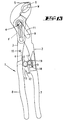
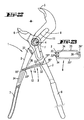
- Fig. 1
- die Zange in Seitenansicht in federbelasteter Grundstellung, gemäß erstem Ausführungsbeispiel,
- Fig. 2
- eine Herausvergrößerung der Fig. 1, die Position des Gelenkbolzens darstellend,
- Fig. 3
- die Zange in Seitenansicht, geschlossen,
- Fig. 4
- die Rückansicht der Zange,
- Fig. 5
- eine Seitenansicht der Zange mit gegriffenem Objekt,
- Fig. 6
- eine Herausvergrößerung, die dann vorliegende Position des Gelenkbolzens zeigend,
- Fig. 7
- eine Herausvergrößerung der Anlenkung der Feder,
- Fig. 8
- den Schnitt gemäß Linie VIII-VIII in Fig. 7,
- Fig. 9
- die Feder in Seitenansicht,
- Fig. 10
- die Feder in Draufsicht,
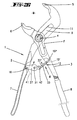
- Fig. 11
- die Zange in Seitenansicht, gemäß zweitem Ausführungsbeispiel, in federbelasteter Öffnungsstellung,
- Fig. 12
- die andere Seite der Zange zeigend in Stellung gemäß Fig. 11,
- Fig. 13
- diese Zange geschlossen,
- Fig. 14
- die Zange unter Greifen eines Objekts,
- Fig. 15
- die Feder dieser Zange in Seitenansicht,
- Fig. 16
- eine Draufsicht hierzu,
- Fig. 17
- die Zange in Seitenansicht, gemäß drittem Ausführungsbeispiel, in federbelasteter Öffnungsstellung,
- Fig. 18
- die Zange in Seitenansicht gemäß viertem Ausführungsbeispiel, in federbelasteter Öffnungsstellung,
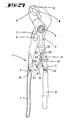
- Fig. 19
- die Zange in Seitenansicht, gemäß fünftem Ausführungsbeispiel in federbelasteter Öffnungsstellung,
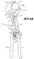
- Fig. 20
- die Zange in Seitenansicht, gemäß sechstem Ausführungsbeispiel, in federbelasteter Öffnungsstellung,
- Fig. 21
- den Schnitt gemäß Linie XXI-XXI in Fig. 20, vergrößert,
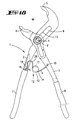
- Fig. 22
- die Zange in Seitenansicht, gemäß siebtem Ausführungsbeispiel, in federbelasteter Öffnungsstellung,
- Fig. 23
- die Feder in Einzeldarstellung, die Führungsanlenkung in dem einen Zangenschenkel zeigend,
- Fig. 24
- die Zange in Seitenansicht, gemäß achtem Ausführungsbeispiel, in federbelasteter Öffnungsstellung,
- Fig. 25
- diese Zange in Seitenansicht, geschlossen, ohne Objekt,
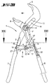
- Fig. 26
- die Zange in Seitenansicht gemäß neuntem Ausführungsbeispiel, in federbelasteter Öffnungsstellung,
- Fig. 27
- diese Zange in Seitenansicht, geschlossen, ohne Objekt.
Claims (15)
- Einhandbetätigbare, sich selbst zustellende Zange (1) mit zwei Zangenschenkeln (2, 3), die mittels eines Gelenkbolzens (4) in einem Kreuzungsbereich miteinander verbunden sind, wobei an einer Seite des Kreuzungsbereichs der Zangenschenkel (2, 3) ein Zangenmaul (M) und an der gegenüberliegenden Seite unterhalb des Kreuzungsbereichs an den Zangenschenkeln (2, 3) Griffabschnitte (7, 8) ausgebildet sind, wobei der eine zur Veränderung der Größe des Zangenmaules (M) im Kreuzungsbereich relativ zum anderen Zangenschenkel (2) verstellbare Zangenschenkel (3) einen Freiraum (F) aufweist, der vom anderen Zangenschenkel (2) durchsetzt ist oder der nicht verstellbare Zangenschenkel vom verstellbaren Zangenschenkel durchsetzt ist, und wobei weiter die Zangenschenkel (2, 3) über ein Steuerelement (13) und einen Federtrieb (12), der das Zangenmaul (M) in eine Öffnungsstellung vorspannt, verbunden sind, welche Öffnungsstellung sich nach Entlastung der Griffabschnitte (7,8) selbsttätig federbelastet herbeiführt, wobei überdies in einem ersten Bewegungsabschnitt des Federtriebs (12) die Zangenmaulbacken (5, 6) aufeinander zu fahren und in einem zweiten Bewegungsabschnitt ein Eingriff einer Klinke (10) des Gelenkbolzens (4) in eine Rastverzahnung (11) erfolgt, wonach eine Kraftverdrehung der beweglichen Zangenmaulbacke (6) um den Gelenkbolzen (4) durchführbar ist, dadurch gekennzeichnet, dass der Federtrieb (12) zugleich die Funktion des Steuerelements 13 erfüllt, wobei dieser Federtrieb (12) sich aus einer Feder (14) mit zwei Federabschnitten (a, b') zusammensetzt, weibei ein Federabschnitt (b') als Starrabschnitt (27) ausgebildet ist, wobei der Starrabschnitt (27) mit dem anderen Zangenschenkel (2) und der Federabschnitt (a) mit dem verstellbaren Schenkel (3) verbunden sind, wobei ein Drehanschlag (19) für den Starrabschnitt (27) an dem anderen Zangenschenkel (2) ausgebildet ist, so dass in unbetätigtem Zustand der Starrabschnitt (27) gegen den an dem anderen Zangenschenkel (2) ausgebildeten Drehanschlag (19) anliegt, und dass bei Verlagerung des verstellbaren Zangenschenkels (3) in eine ein Werkstück erfassende Maulschließlage der Starrabschnitt (27) erst nach Kraftbetätigung bei Anlage der Zangenmaulbacken (5, 6) an dem Werkstück von dem Drehanschlag (19) freikommt.
- Zange nach Anspruch 1, dadurch gekennzeichnet, dass der Starrabschnitt (b') ein Lenker (27) ist, an dessen einem Ende das Federelement befestigt ist, und dessen anderes Ende drehbar an dem Zangenschenkel (2) angeordnet ist.
- Zange nach Anspruch 2, dadurch gekennzeichnet, dass der Lenker (27) paarig ausgebildet ist und durch Beabstandung der beiden Lenker (27) einen Freiraum für die Feder (14) und die Federbefestigung beläßt.
- Zange nach einem der Ansprüche 1 bis 3, dadurch gekennzeichnet, dass der Federabschnitt (a) durch eine Spiralfeder (25) gebildet ist.
- Zange nach Anspruch 3 oder 4, dadurch gekennzeichnet, dass die Federbefestigung durch einen das Windungspaket der Federwindung (17) durchsetzenden, die Lenker (27) verbindenden Tragzapfen (29) erzielt ist.
- Zange nach einem der Ansprüche 1 bis 5, dadurch gekennzeichnet, dass der dem Starrabschnitt (b') zugewandte Federabschnitt (b) der als Drehschenkelfeder ausgebildeten Feder (14) sich am Starrabschnitt (b') abstützt.
- Zange nach Anspruch 6, dadurch gekennzeichnet, dass die Abstützung von einem gleichfalls die Lenker (27) verbindenden Zapfen (30) gebildet ist.
- Zange nach einem der Ansprüche 1 bis 7, dadurch gekennzeichnet, dass die Feder (14) als Bügelfeder (B) mit Bügelarmen (33, 33') und einer Bügelkehre (33") ausgebildet ist, wobei die Bügelarme (33, 33') oder die Bügelkehre (33") vermittels des an einem Zangenschenkel (2) drehbar gelagenten Starrabschnitts (b') abgestützt sind.
- Zange nach Anspruch 8, dadurch gekennzeichnet, dass die Bügelarme (33, 33') an einem Starrabschnitt (b') bzw. einem Zangenschenkel (2 bzw. 3) über unterschiedliche Drehachsen (15', 15", 16', 16") drehbar abgestützt sind.
- Zange nach einem der Ansprüche 8 oder 9, dadurch gekennzeichnet, dass die Bügelarme (33, 33') unterschiedlich lang ausgebildet sind.
- Zange nach einem der Ansprüche 8 bis 10, dadurch gekennzeichnet, dass die Bügelarme (33, 33') einen gekrümmten Verlauf aufweisen.
- Zange nach Anspruch 11, dadurch gekennzeichnet, dass die Krümmung dem Zangenmaul (M) zugewandt konkav ist.
- Zange nach einem der Ansprüche 8 bis 12, dadurch gekennzeichnet, dass die Bügelkehre (33") U-förmig ausgebildet ist.
- Zange nach einem der Ansprüche 8 bis 12, dadurch gekennzeichnet, dass die Bügelkehre (33") wendelförmig ausgebildet ist.
- Zange nach einem der Ansprüche 1 bis 14 dadurch gekennzeichnet, dass an dem Starrabschnitt (b') ein bei Streckstellung des Federtriebs (12) mit der Feder (14) zusammenwirkender Anschlag (42) ausgebildet ist.
Applications Claiming Priority (5)
| Application Number | Priority Date | Filing Date | Title |
|---|---|---|---|
| DE19840741 | 1998-09-07 | ||
| DE19840741 | 1998-09-07 | ||
| DE19940485 | 1999-08-26 | ||
| DE19940485.2A DE19940485B4 (de) | 1998-09-07 | 1999-08-26 | Einhandbetätigbare, sich selbst zustellende Zange |
| PCT/EP1999/006560 WO2000013856A1 (de) | 1998-09-07 | 1999-09-07 | Einhandbetätigbare, sich selbst zustellende zange |
Publications (2)
| Publication Number | Publication Date |
|---|---|
| EP1112149A1 EP1112149A1 (de) | 2001-07-04 |
| EP1112149B1 true EP1112149B1 (de) | 2003-11-12 |
Family
ID=26048682
Family Applications (1)
| Application Number | Title | Priority Date | Filing Date |
|---|---|---|---|
| EP99946136A Expired - Lifetime EP1112149B1 (de) | 1998-09-07 | 1999-09-07 | Einhandbetätigbare, sich selbst zustellende zange |
Country Status (8)
| Country | Link |
|---|---|
| US (1) | US6502482B1 (de) |
| EP (1) | EP1112149B1 (de) |
| JP (1) | JP4412851B2 (de) |
| CN (1) | CN1144655C (de) |
| AU (1) | AU5861199A (de) |
| ES (1) | ES2209505T3 (de) |
| RU (1) | RU2261168C2 (de) |
| WO (1) | WO2000013856A1 (de) |
Families Citing this family (31)
| Publication number | Priority date | Publication date | Assignee | Title |
|---|---|---|---|---|
| DE29907864U1 (de) | 1999-05-03 | 1999-07-29 | Odo Klose & Partner Prof | Wasserpumpenzange mit Einhandbedienung |
| US20030167881A1 (en) * | 2000-05-12 | 2003-09-11 | Eric Chauffeteau | Collar clamping pliers |
| US20040217547A1 (en) * | 2000-07-17 | 2004-11-04 | Lau Edward E. | Method of playing a new wagering card game |
| DE10343412A1 (de) * | 2003-05-22 | 2004-12-09 | Knipex-Werk C. Gustav Putsch Kg | Einhandbetätigbare Zange |
| JP4490972B2 (ja) * | 2003-05-22 | 2010-06-30 | クニペックス−ウエルク・ツエ・グスタフ・プッチュ・カーゲー | 片手で操作できるペンチ |
| US7144402B2 (en) * | 2003-06-16 | 2006-12-05 | Synovis Life Technologies, Inc. | Vascular clamp |
| US7406898B1 (en) | 2003-09-03 | 2008-08-05 | Hall Jr Herbert L | Adjustable pliers having slidably mounted jaw |
| US7191688B1 (en) | 2003-09-03 | 2007-03-20 | Hall Jr Herbert L | Force augmentation and jaw adjustment means for hand held tools |
| JP4740842B2 (ja) * | 2004-03-26 | 2011-08-03 | 株式会社牧野フライス製作所 | 切削加工方法及び装置 |
| GB0721292D0 (en) * | 2007-10-30 | 2007-12-12 | Buchanan Nigel A | Hand operated gripping tool |
| US7347125B1 (en) * | 2006-09-13 | 2008-03-25 | Daniel Juieng | Automatic adjustable head wrench |
| US8276429B2 (en) * | 2006-10-02 | 2012-10-02 | Emerson Electric Co. | Hand tools and handles therefor |
| DE102007049032B4 (de) * | 2006-10-24 | 2021-03-18 | Knipex-Werk C. Gustav Putsch Kg | Zange |
| GB2453331A (en) * | 2007-10-01 | 2009-04-08 | Wendeng Maxpower Tool Group Co Ltd | Self-adjusting pliers with spacing means |
| US7681477B2 (en) * | 2008-01-31 | 2010-03-23 | The Stanley Works | Adjustable pliers |
| DE102008012969A1 (de) | 2008-03-06 | 2009-09-10 | Will Werkzeuge Gmbh & Co. Kg | Einhandbetätigbare Zange |
| CN201455835U (zh) * | 2009-07-16 | 2010-05-12 | 杭州巨星科技股份有限公司 | 快速水泵钳 |
| FI20096328A (fi) * | 2009-12-15 | 2011-06-16 | Fiskars Brands Finland Oy Ab | Menetelmä käsityökalun kädensijan valmistamiseksi ja käsityökalun kädensija |
| US8137379B2 (en) * | 2010-05-03 | 2012-03-20 | Josiah Labash | Pressure-applying device |
| US9106062B2 (en) | 2011-06-06 | 2015-08-11 | Hubbell Incorporated | Geared spacer assembly for conductor bundle |
| JP5289513B2 (ja) * | 2011-06-30 | 2013-09-11 | 株式会社ツノダ | 開閉作業工具 |
| CN203077167U (zh) * | 2013-01-25 | 2013-07-24 | 浙江亿洋工具制造有限公司 | 一种管子钳 |
| DE102013217874B3 (de) * | 2013-09-06 | 2014-11-27 | Wiha Werkzeuge Gmbh | Zange |
| DE102014102927A1 (de) * | 2014-03-05 | 2015-09-10 | Knipex-Werk C. Gustav Putsch Kg | Zange |
| US10406655B2 (en) | 2014-06-30 | 2019-09-10 | Hangzhou Great Star Tools Co., Ltd | Adjustable plier |
| JP5972934B2 (ja) * | 2014-06-30 | 2016-08-17 | 株式会社ツノダ | 開閉作業工具 |
| GB2540621A (en) * | 2015-07-24 | 2017-01-25 | Stanley Works (Europe) Ag | Adjustable pliers |
| US9807992B2 (en) | 2015-09-14 | 2017-11-07 | Deshano, Inc. | Crankbait tuning device |
| CN107344340B (zh) * | 2016-05-06 | 2019-05-17 | 共茂工业股份有限公司 | 可自动夹固的钳子 |
| US20190105757A1 (en) * | 2017-10-09 | 2019-04-11 | Clifton Jackson | Multiple function tool apparatus |
| DE102018111873A1 (de) * | 2018-05-17 | 2019-11-21 | Gustav Klauke Gmbh | Presszange |
Family Cites Families (19)
| Publication number | Priority date | Publication date | Assignee | Title |
|---|---|---|---|---|
| US1048298A (en) * | 1912-03-13 | 1912-12-24 | John K Daniels | Wrench. |
| US2531285A (en) * | 1948-03-08 | 1950-11-21 | Edward L Manspeaker | Wrench with self-adjusting jaws |
| US2906155A (en) | 1956-09-07 | 1959-09-29 | Wendell S Miller | Pliers with automatic fulcrum shift |
| US3176551A (en) * | 1962-03-19 | 1965-04-06 | Burton R Hansen | Convertible jaw pliers |
| FR2052020A5 (de) * | 1969-07-11 | 1971-04-09 | Stephanoises Forges | |
| US4651598B1 (en) | 1984-09-26 | 1997-09-09 | William A Warheit | Self-adjusting utility plier |
| US4893530A (en) * | 1987-03-19 | 1990-01-16 | Warheit William A | Plier-type tool |
| US5850768A (en) * | 1995-09-07 | 1998-12-22 | Chow; Jessie | Pliers for gripping workpieces of different sizes |
| EP0854011B1 (de) * | 1997-01-20 | 2001-03-28 | Tool Design Corporation Hand | Zange zum Greifen von Werkstücken verschiedener Abmessungen |
| US6161455A (en) * | 1997-08-12 | 2000-12-19 | Great Neck Saw Manufacturers, Inc. | Adjustable plier |
| US6116124A (en) * | 1997-08-12 | 2000-09-12 | Great Neck Saw Manufacturers, Inc. | Adjustable pliers |
| US5887495A (en) * | 1997-10-24 | 1999-03-30 | Kao; Hung-Tien | Pliers |
| US6000303A (en) * | 1998-03-05 | 1999-12-14 | Chang; Jong-Shing | Pliers |
| US5970827A (en) * | 1998-03-06 | 1999-10-26 | Lin; Chien-Jung | Adjustable plier device |
| DE29803998U1 (de) * | 1998-03-06 | 1998-05-28 | Chang Jong Shing | Zange |
| ES1043181Y (es) * | 1999-05-03 | 2000-04-01 | Super Ego Tools | Tenaza ajustable perfeccionada. |
| DE29907864U1 (de) * | 1999-05-03 | 1999-07-29 | Odo Klose & Partner Prof | Wasserpumpenzange mit Einhandbedienung |
| CA2276121C (en) * | 1999-06-21 | 2004-03-30 | Super-Ego Tools, S.A. | Self-adjusting pliers |
| US6155142A (en) * | 1999-08-13 | 2000-12-05 | B!G Ventures, Llc | Pliers with force augmentation and self-adjustment capability |
-
1999
- 1999-09-07 JP JP2000568645A patent/JP4412851B2/ja not_active Expired - Fee Related
- 1999-09-07 WO PCT/EP1999/006560 patent/WO2000013856A1/de active IP Right Grant
- 1999-09-07 EP EP99946136A patent/EP1112149B1/de not_active Expired - Lifetime
- 1999-09-07 US US09/786,670 patent/US6502482B1/en not_active Expired - Lifetime
- 1999-09-07 AU AU58611/99A patent/AU5861199A/en not_active Abandoned
- 1999-09-07 RU RU2001109237/11A patent/RU2261168C2/ru not_active IP Right Cessation
- 1999-09-07 ES ES99946136T patent/ES2209505T3/es not_active Expired - Lifetime
- 1999-09-07 CN CNB998106364A patent/CN1144655C/zh not_active Expired - Fee Related
Also Published As
| Publication number | Publication date |
|---|---|
| AU5861199A (en) | 2000-03-27 |
| CN1144655C (zh) | 2004-04-07 |
| RU2261168C2 (ru) | 2005-09-27 |
| WO2000013856A1 (de) | 2000-03-16 |
| US6502482B1 (en) | 2003-01-07 |
| CN1316941A (zh) | 2001-10-10 |
| EP1112149A1 (de) | 2001-07-04 |
| ES2209505T3 (es) | 2004-06-16 |
| JP4412851B2 (ja) | 2010-02-10 |
| JP2002524284A (ja) | 2002-08-06 |
| RU2001109237A (ru) | 2003-05-10 |
Similar Documents
| Publication | Publication Date | Title |
|---|---|---|
| EP1112149B1 (de) | Einhandbetätigbare, sich selbst zustellende zange | |
| EP1236543B1 (de) | Klemm- oder Spreizzange | |
| EP2054195B1 (de) | Zange mit entgegen der kraft einer feder bewegbarem gelenkbolzen | |
| DE102006013847B4 (de) | Kraftfahrzeugsitz | |
| EP2493663B1 (de) | Montagezange mit lösbarer gegenklinke | |
| DE2713410A1 (de) | Zange, insbesondere zum anbringen von ohrmarkierungen bei tieren | |
| DE1801310B2 (de) | Verdecktes Scharniergelenk für Türen, Klappen o.dgl | |
| EP1624996B1 (de) | Einhandbetätigbare zange | |
| DE2831291C2 (de) | Fahrzeugsitz | |
| EP2512744A1 (de) | Zange | |
| WO2001005646A1 (de) | Roller | |
| DE102018123160A1 (de) | Rahmen | |
| DE3642958A1 (de) | Einstueckiger, elastisch schliessender klemmbuegel | |
| EP3563973B1 (de) | Zange | |
| DE19933033B4 (de) | Klemm- oder Spreizzange | |
| DE19940485A1 (de) | Einhandbetätigbare, sich selbst zustellende Zange | |
| CH666799A5 (de) | Verkuerzbarer schirm. | |
| DE2638550A1 (de) | Haar-clip mit blattfederscharnier | |
| EP2252435B1 (de) | Einhandbetätigbare zange | |
| DE867152C (de) | Selbstschliessender Taschenbuegel | |
| EP2418094B1 (de) | Zirkel | |
| EP0366147B1 (de) | Abklappbarer Aussenspiegel für Fahrzeuge | |
| DE920216C (de) | Gartenschere | |
| DE160956C (de) | ||
| WO1994029078A1 (de) | Zange mit zwei zangenschenkeln und einem zangenmaul |
Legal Events
| Date | Code | Title | Description |
|---|---|---|---|
| PUAI | Public reference made under article 153(3) epc to a published international application that has entered the european phase |
Free format text: ORIGINAL CODE: 0009012 |
|
| 17P | Request for examination filed |
Effective date: 20010317 |
|
| AK | Designated contracting states |
Kind code of ref document: A1 Designated state(s): AT BE CH CY DE DK ES FI FR GB GR IE IT LI LU MC NL PT SE |
|
| 17Q | First examination report despatched |
Effective date: 20010719 |
|
| GRAH | Despatch of communication of intention to grant a patent |
Free format text: ORIGINAL CODE: EPIDOS IGRA |
|
| GRAS | Grant fee paid |
Free format text: ORIGINAL CODE: EPIDOSNIGR3 |
|
| GRAA | (expected) grant |
Free format text: ORIGINAL CODE: 0009210 |
|
| RAP1 | Party data changed (applicant data changed or rights of an application transferred) |
Owner name: KNIPEX-WERK C. GUSTAV PUTSCH KG |
|
| AK | Designated contracting states |
Kind code of ref document: B1 Designated state(s): DE ES FR GB IT SE |
|
| REG | Reference to a national code |
Ref country code: GB Ref legal event code: FG4D Free format text: NOT ENGLISH |
|
| REF | Corresponds to: |
Ref document number: 59907739 Country of ref document: DE Date of ref document: 20031218 Kind code of ref document: P |
|
| REG | Reference to a national code |
Ref country code: IE Ref legal event code: FG4D Free format text: GERMAN |
|
| REG | Reference to a national code |
Ref country code: SE Ref legal event code: TRGR |
|
| GBT | Gb: translation of ep patent filed (gb section 77(6)(a)/1977) |
Effective date: 20040225 |
|
| ET | Fr: translation filed | ||
| REG | Reference to a national code |
Ref country code: ES Ref legal event code: FG2A Ref document number: 2209505 Country of ref document: ES Kind code of ref document: T3 |
|
| REG | Reference to a national code |
Ref country code: IE Ref legal event code: FD4D |
|
| PLBE | No opposition filed within time limit |
Free format text: ORIGINAL CODE: 0009261 |
|
| STAA | Information on the status of an ep patent application or granted ep patent |
Free format text: STATUS: NO OPPOSITION FILED WITHIN TIME LIMIT |
|
| 26N | No opposition filed |
Effective date: 20040813 |
|
| PGFP | Annual fee paid to national office [announced via postgrant information from national office to epo] |
Ref country code: GB Payment date: 20110907 Year of fee payment: 13 Ref country code: SE Payment date: 20110907 Year of fee payment: 13 |
|
| PGFP | Annual fee paid to national office [announced via postgrant information from national office to epo] |
Ref country code: ES Payment date: 20110905 Year of fee payment: 13 |
|
| PG25 | Lapsed in a contracting state [announced via postgrant information from national office to epo] |
Ref country code: SE Free format text: LAPSE BECAUSE OF NON-PAYMENT OF DUE FEES Effective date: 20120908 |
|
| REG | Reference to a national code |
Ref country code: SE Ref legal event code: EUG |
|
| GBPC | Gb: european patent ceased through non-payment of renewal fee |
Effective date: 20120907 |
|
| PG25 | Lapsed in a contracting state [announced via postgrant information from national office to epo] |
Ref country code: GB Free format text: LAPSE BECAUSE OF NON-PAYMENT OF DUE FEES Effective date: 20120907 |
|
| REG | Reference to a national code |
Ref country code: ES Ref legal event code: FD2A Effective date: 20131018 |
|
| PG25 | Lapsed in a contracting state [announced via postgrant information from national office to epo] |
Ref country code: ES Free format text: LAPSE BECAUSE OF NON-PAYMENT OF DUE FEES Effective date: 20120908 |
|
| REG | Reference to a national code |
Ref country code: FR Ref legal event code: PLFP Year of fee payment: 18 |
|
| PGFP | Annual fee paid to national office [announced via postgrant information from national office to epo] |
Ref country code: FR Payment date: 20160915 Year of fee payment: 18 |
|
| PGFP | Annual fee paid to national office [announced via postgrant information from national office to epo] |
Ref country code: IT Payment date: 20160928 Year of fee payment: 18 |
|
| PGFP | Annual fee paid to national office [announced via postgrant information from national office to epo] |
Ref country code: DE Payment date: 20171016 Year of fee payment: 19 |
|
| REG | Reference to a national code |
Ref country code: FR Ref legal event code: ST Effective date: 20180531 |
|
| PG25 | Lapsed in a contracting state [announced via postgrant information from national office to epo] |
Ref country code: FR Free format text: LAPSE BECAUSE OF NON-PAYMENT OF DUE FEES Effective date: 20171002 Ref country code: IT Free format text: LAPSE BECAUSE OF NON-PAYMENT OF DUE FEES Effective date: 20170907 |
|
| REG | Reference to a national code |
Ref country code: DE Ref legal event code: R119 Ref document number: 59907739 Country of ref document: DE |
|
| PG25 | Lapsed in a contracting state [announced via postgrant information from national office to epo] |
Ref country code: DE Free format text: LAPSE BECAUSE OF NON-PAYMENT OF DUE FEES Effective date: 20190402 |