EP1108674A2 - Einbaumethode Einer Rolltreppe - Google Patents
Einbaumethode Einer Rolltreppe Download PDFInfo
- Publication number
- EP1108674A2 EP1108674A2 EP00105220A EP00105220A EP1108674A2 EP 1108674 A2 EP1108674 A2 EP 1108674A2 EP 00105220 A EP00105220 A EP 00105220A EP 00105220 A EP00105220 A EP 00105220A EP 1108674 A2 EP1108674 A2 EP 1108674A2
- Authority
- EP
- European Patent Office
- Prior art keywords
- escalator
- pit
- stairway
- drilled
- frame
- Prior art date
- Legal status (The legal status is an assumption and is not a legal conclusion. Google has not performed a legal analysis and makes no representation as to the accuracy of the status listed.)
- Granted
Links
Images
Classifications
-
- B—PERFORMING OPERATIONS; TRANSPORTING
- B66—HOISTING; LIFTING; HAULING
- B66B—ELEVATORS; ESCALATORS OR MOVING WALKWAYS
- B66B21/00—Kinds or types of escalators or moving walkways
Definitions
- the present invention relates to an escalator installation method for installing an escalator at a position where a stairway is provided in a station and the like.
- a first drilled portion is formed by drilling an upper floor positioned on an upper side of a stairway; a second drilled portion is formed by drilling a lower floor positioned on a lower side of the stairway; an upper flat portion of the escalator is housed in the first drilled portion of the upper floor; a lower flat portion of the escalator is housed in the second drilled portion of the lower floor; and an inclined portion of the escalator is arranged on the stairway portion positioned between the first drilled portion and the second drilled portion.
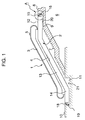
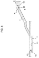
- escalator which is a target of the present invention will be explained in conjunction with Figs. 1 to 3.
- the escalator shown in Figs. 1 to 3 is, e.g., a thin escalator in which a height of a frame forming a main body is smaller than that in a regular escalator as will be described later.
- the escalator 1 shown in Fig. 1 includes a frame 2 for forming a main body; a balustrade 3 erected on the frame 2, steps 4 for conveying a passenger, a handrail 5 for moving in synchronism with the steps 4, and others.
- the escalator 1 depicted in Fig. 1 has such a structure as that the entire frame 2 is constituted by an integral structure and, for example, the balustrade 3 erected on the frame 2, the steps 4 and the handrail 5 are also integrally provided to the frame 2.
- An architectural structure 6 provided with the escalator 1 includes a stairway 7, and a first drilled portion, i.e., an upper pit 9 obtained by partially drilling an upper floor positioned on the upper side of the stairway 7, i.e., an upper story floor 8 is provided to the upper story floor 8. Further, to a lower floor positioned on the lower side of the stairway 7, i.e., a lower story floor 10 is provided a second drilled portion, i.e., a lower pit 11 obtained by partially drilling the lower story floor 10.
- An upper flat portion 12 of the escalator 1 is provided in the upper pit 9 whilst a lower flat portion 14 is provided in the lower pit 10, and an inclined portion 13 is so arranged as to be opposed to the stairway 7.
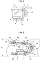
- an upper end portion 15 of the frame 2 is supported on a building beam 16 through a shim 17.
- a lower end portion 18 of the frame 2 is supported on a building beam 19 of the architectural structure 6 through the shim.
- the escalator 1 has such a structure as that a part of the upper flat portion 12 positioned below the upper end portion 15 of the frame 2 is distanced from a bottom surface 20 of the upper pit 9 as shown in Fig. 1. Similarly, a part of the lower flat portion 14 positioned below the lower end portion 18 of the frame 2 is distanced from a bottom surface 21 of the lower pit 11.
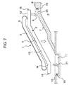
- a drive sprocket 23 which has a smaller diameter than that in a general escalator and has, e.g., 18 wheel teeth is arranged in the reverse portion 22 of the step 4 provided to the upper flat portion 12 of the frame 2.
- a front wheel 24 of the step 4 is guided by a front wheel guide rail 25, and a rear wheel 26 of the step 4 is guided by a rear wheel guide rail 27.
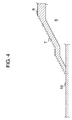
- a movement locus of the front wheel guide rail 25 is positioned outside the rear wheel guide rail 27 in the width direction of the frame 2, i.e., a direction orthogonal to the page of Fig. 3.
- the front wheel shaft of each step 4 is connected to the chains 28.
- a triangular specific link 29 is connected to the chains 28 every six links (pitches) and the front wheel shaft is connected to the specific link 29.
- An oval hole 30 for enabling displacement of the front wheel shaft is formed in the specific link 29.
- the oval hole 30 is extended in a direction substantially orthogonal to an extensional direction of the chain 28.
- step 4 moving in an outward route becomes close to the reverse portion 22
- the tread of the step 4 is turned up and horizontally held and the front wheel shaft is positioned on the lower end of the oval hole 30 of the specific link 29 when the step 4 is still positioned on the near side.
- the front wheel shaft move so as to be parallel to the extensional direction of the oval hole 30 of the specific line 29 and, when the front wheel 24 comes closer to the substantially intermediate-height position of the drive sprocket 23, the front wheel shaft 24 is positioned on the upper end of the over hole 30, i.e., the rightmost end in Fig. 3.
- the front wheel shaft is again positioned on the lower end of the over hole 30 of the specific link 29.
- Such an operation causes the movement locus 31 of the chain 28 and the movement locus 32 of the front wheel shaft of the step 4 to substantially coincide with each other in the outward route to the reverse portion 22 and the inward route after passing the reverse portion 22, but the movement locus 32 of the front wheel shaft is positioned outside the movement locus 31 of the chain 28 in the reverse portion 22. That is, it becomes a movement locus approximating the counterpart of the chain wound around the drive sprocket provided to the regular escalator which is not thin. Therefore, the step 4 which is to be reversed and the step 4 adjacent thereto do not interfere with each other, thereby smoothing the reversal operation of these steps 4.
- a height H of the frame 2 illustrated in Fig. 3 can be reduced, e.g., 20 to 30% in the first embodiment as compared with the height of the frame in the regular escalator. Accordingly, the escalator 1 can be constructed as a thin escalator whose overall height is lower than that of the regular escalator.
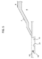
- the first embodiment is a method for installing the thin escalator 1 to the aforesaid architectural structure 6 and, as shown in Fig. 4, the architectural structure 6 is provided with the upper story floor 8 and the lower story floor 10, and the stairway 7 forming a pedestrian passage is provided between the upper story floor 8 and the lower story floor 10.
- This architectural structure 6 is, for example, a railroad station, and the escalator 1 is provided on the existing stairway 7 in the first embodiment.
- a part of the lower story floor 10 positioned in the vicinity of the lowermost portion of the stairway 7 is first drilled to carry out a first process for forming the lower pit 11.
- the vicinity of the uppermost portion of the stairway 7 and a part of the upper story floor 8 are then drilled to conduct a second process for forming the upper pit 9, as shown in Fig. 6.
- a part of the stairway 7 positioned between the upper pit 9 and the lower pit 9 are maintained so as not to be drilled, and a third process is performed by which: the escalator 1 constituted by the above-described thin integral structure described with reference to Figs. 1 to 3 is carried to the stairway 7; the lower flat portion 14 is accommodated in the lower pit 11; the upper flat portion 12 is housed in the upper pit 9; and escalator 1 is installed in such a manner that the inclined portion 13 is arranged above the part of the stairway 7 positioned between the upper pit 9 and the lower pit 11.
- the third process there are effected an operation for supporting the upper end portion 15 of the frame 2 in the escalator 1 on the building beam 16 of the architectural structure 6 through the shim 17 (Fig. 2) and another operation for supporting the lower end portion 18 of the frame 2 on the building beam 19 of the architectural structure 6 through the shim.
- the part of the upper flat portion 12 positioned below the upper end portion 15 of the frame 2 is so arranged as to be distanced from the bottom surface 20 of the upper pit 9
- the part of the lower flat portion 14 positioned below the lower end portion 18 of the frame 2 is so arranged as to be distanced from the bottom surface 21 of the lower pit 11.
- the top face of the upper flat portion 12 of the thin escalator 1 and the upper story floor 8 are formed in plane; the top face of the lower flat portion 14 and the lower story floor 10 are formed in plane; and the inclined portion 13 positioned between the upper flat portion 12 and the lower flat portion 14 is installed so as to be distanced away from the stairway 7.
- the escalator 1 can be installed without requiring the drilling operation over the entire length of the escalator 1, i.e., the chipping operation for the stairway 7. Therefore, a number of processes in the drilling operation can be reduced to improve the installing operation efficiency. This also enables reduction in the time period required for installing the escalator 1, which can satisfy the need for using the escalator as soon as possible.
- the thin escalator 1 is installed in the first embodiment, although not shown in Fig. 1 and others, the sufficient height from the stairway 7 to a ceiling portion can be assured if the architectural structure 6 has the ceiling portion, and no problem occurs in conveyance of passengers by this escalator 1.
- the entire escalator 1, including the frame 2 is constituted by the integral structure, the operation for connecting the frame is not required in the installation on the spot, which further reduces a number of processes in the installing operation, contributing to improvement in the operation efficiency.
- the building beams 16 and 19 receive a load of the escalator 1, which can stabilize the escalator 1, thereby realizing the installation with high accuracy.
- the load of the escalator 1 is not transmitted to the bottom surface 20 of the upper pit 9 and the bottom surface 21 of the lower pit 11, and the safety protection for the installation environment of the escalator 1 can be realized without a concern of a deformation of or a damage to the bottom surfaces 20 and 21.
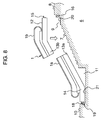
- Fig. 8 is a side elevation showing a primary part in section for explaining a second embodiment of an installation method according to the present invention.
- the escalator 1 is constituted by a thin escalator and includes, for example, a lower divided portion la including a frame first divided portion 13a and an upper divided portion 1b including a frame second divided portion 13b.
- a part of the lower story floor 10 positioned in the vicinity of the lowermost portion of the stairway 7 is drilled to form the lower pit 11 as the first process.
- the vicinity of the uppermost portion of the stairway 7 and a part of the upper story floor 8 are drilled to form the upper pit 9.
- the part of the stairway 7 positioned between the upper pit 9 and the lower pit 11 is maintained so as not to be drilled.
- the lower flat portion 14 included in the lower divided portion la is provided in the lower pit 11 with no upper divided portion 1b existing in the installation position of the escalator 1, and the upper flat portion 12 included in the upper divided portion 1b is then provided in the upper pit 9. Thereafter, the lower divided portion 1a and the upper divided portion 1b are connected to each other.
- the upper flat portion 12 included in the upper divided portion 1b is provided in the upper pit 9 with no lower divided portion la existing in the installation position of the escalator 1, and the lower flat portion 14 included in the lower divided portion 1a is then provided in the lower pit 11. Subsequently, the upper divided portion 1b and the lower divided portion la are connected to each other.
- the operation is carried out by which the lower end portion 18 of the lower divided portion la is supported on the building beam 19 of the architectural structure 6 through the shim; the upper end portion 15 of the upper divided portion 1b is supported on the building beam 16 of the architectural structure 6 through the shim; the part of the lower flat portion 14 positioned below the lower end portion 18 of the lower divided portion la is arranged so as to be distanced from the bottom surface 21 of the lower pit 11; and the part of the upper flat portion 12 positioned below the upper end portion 15 of the upper divided portion 1b is arranged so as to be distanced from the bottom surface 20 of the upper pit 9.
- the part of the stairway 7 positioned between the upper pit 9 and the lower pit 11 is not drilled, and hence the results similar to those in the first embodiment can be obtained.
- the lower divided portion 13a is carried to the vicinity of the lower pit 11 to be set to a predetermined position with no upper divided portion 13b existing in the installation position of the escalator 1.
- the upper divided portion 13b is carried to the vicinity of the upper pit 9 to be set to a predetermined position with no lower divided portion la existing in the installation position of the escalator 1.
- the respective divided portions 1b and 1a can be readily treated since the these divided portions 1b and 1a are light in weight as compared with the escalator which is entirely constituted by the integral structure, and the installation operation can be thereby facilitated, which contributes to improvement in the operation efficiency.
- the thin escalator 1 is installed in the foregoing embodiments, the conventionally-used regular escalator may be installed if the ceiling portion has a sufficient height.
- the present invention is not restricted to these processes, and the upper pit 9 may be formed by drilling as the first process and the lower pit 11 may be formed by drilling as the second process.
- the escalator 1 is supported by the both building beams 16 and 19 of the architectural structure 6 in the foregoing embodiments, but it may be supported by either one. Further, the escalator 1 may be supported by any other support without using the building beams 16 and 19.
- the part of the upper flat portion 12 positioned below the upper end portion 15 of the escalator 1 and the part of the lower flat portion 14 positioned below the lower end portion 18 are distanced from the bottom surface 20 of the upper pit 9 and the bottom surface 21 of the lower pit 21, respectively, in the foregoing embodiments, either of these parts may be mounted on the bottom surface of the pit. If the sufficient strength of the bottom surface of the pit is assured, the both parts may be mounted on the bottom surfaces of the pits.
- the escalator 1 takes the shape of the integral structure in the first embodiment, only the frame 2 may be constituted by the integral structure and other members such as the balustrade 3, the step 4 and the handrail 5 may be disposed after carrying in the frame 2.
- the lower divided portion la takes the shape of the integral structure including the frame first divided portion 13a
- the upper divided portion 1b takes the form of another integral structure including the frame second divided portion 13b, the balustrade portion, the step portion and the handrail portion in the second embodiment, the balustrade, the step, the handrail and others may be disposed after carrying in the frame first divided portion 13a and the frame second divided portion 13b, respectively.
- the escalator 1 is constituted by the two divided portions in the second embodiment, but it may be constituted by three or more divided portions.
- the regular escalator may be constituted in the divided manner when installing the escalator at the position where the sufficient upper space can be assured.
- the escalator can be installed without requiring the drilling operation over the entire length of the escalator to thereby reduce a number of processes in the drilling operation, and the drilling operation efficiency can be improved as compared with the prior art.
- the time period required in the installation of the escalator can be further reduced as compared with the prior art, which can satisfy the need for using the escalator as soon as possible.
Landscapes
- Escalators And Moving Walkways (AREA)
Applications Claiming Priority (2)
| Application Number | Priority Date | Filing Date | Title |
|---|---|---|---|
| JP35805999A JP3456932B2 (ja) | 1999-12-16 | 1999-12-16 | エスカレータの据付工法 |
| JP35805999 | 1999-12-16 |
Publications (3)
| Publication Number | Publication Date |
|---|---|
| EP1108674A2 true EP1108674A2 (de) | 2001-06-20 |
| EP1108674A3 EP1108674A3 (de) | 2004-01-28 |
| EP1108674B1 EP1108674B1 (de) | 2011-12-14 |
Family
ID=18457328
Family Applications (1)
| Application Number | Title | Priority Date | Filing Date |
|---|---|---|---|
| EP00105220A Expired - Lifetime EP1108674B1 (de) | 1999-12-16 | 2000-03-13 | Einbauverfahren für eine Rolltreppe |
Country Status (7)
| Country | Link |
|---|---|
| US (1) | US6247574B1 (de) |
| EP (1) | EP1108674B1 (de) |
| JP (1) | JP3456932B2 (de) |
| CN (1) | CN1176005C (de) |
| MY (1) | MY123419A (de) |
| SG (1) | SG85163A1 (de) |
| TW (1) | TWI237004B (de) |
Cited By (1)
| Publication number | Priority date | Publication date | Assignee | Title |
|---|---|---|---|---|
| WO2010115410A3 (de) * | 2009-04-09 | 2010-12-16 | Kone Corporation | Einrichtung zum personentransport |
Families Citing this family (7)
| Publication number | Priority date | Publication date | Assignee | Title |
|---|---|---|---|---|
| IL151654A (en) * | 2002-09-09 | 2011-02-28 | Oscar Sircovich | Stair raising system |
| US6685002B1 (en) * | 2002-10-15 | 2004-02-03 | Kone Corporation | Method of escalator modernization |
| JP2013508243A (ja) * | 2009-10-19 | 2013-03-07 | オーチス エレベータ カンパニー | 乗客コンベアのトラス構造 |
| ES2894733T3 (es) * | 2013-12-06 | 2022-02-15 | Inventio Ag | Soporte para el montaje en el sitio de un dispositivo de transporte de personas |
| JP6383628B2 (ja) * | 2014-10-14 | 2018-08-29 | 株式会社日立製作所 | 乗客コンベア |
| US9440820B2 (en) * | 2015-01-09 | 2016-09-13 | Kone Coporation | Escalator lifting frame and method of using the same |
| WO2017126177A1 (ja) * | 2016-01-21 | 2017-07-27 | 三菱電機株式会社 | 乗客コンベヤ |
Family Cites Families (6)
| Publication number | Priority date | Publication date | Assignee | Title |
|---|---|---|---|---|
| DE1456371A1 (de) * | 1966-07-30 | 1968-12-05 | Lutz Dr Ing Hermann | Rolltreppe |
| JPH0671995B2 (ja) * | 1986-05-10 | 1994-09-14 | 株式会社日立製作所 | 乗客コンベアのフレームの組立方法 |
| JPH07179284A (ja) * | 1993-12-24 | 1995-07-18 | Hitachi Ltd | 通路設備 |
| CN1187256C (zh) * | 1998-06-11 | 2005-02-02 | 因温特奥股份公司 | 电梯或移动通道 |
| JP2000203781A (ja) * | 1999-01-14 | 2000-07-25 | Nippon Fillester Co Ltd | エスカレ―タの設置構造 |
| JP4410339B2 (ja) * | 1999-05-24 | 2010-02-03 | 三菱電機株式会社 | 乗客コンベヤーの設置方法 |
-
1999
- 1999-12-16 JP JP35805999A patent/JP3456932B2/ja not_active Expired - Fee Related
-
2000
- 2000-03-13 SG SG200001498A patent/SG85163A1/en unknown
- 2000-03-13 EP EP00105220A patent/EP1108674B1/de not_active Expired - Lifetime
- 2000-03-13 MY MYPI20000969A patent/MY123419A/en unknown
- 2000-03-14 US US09/525,027 patent/US6247574B1/en not_active Expired - Fee Related
- 2000-03-15 CN CNB001043188A patent/CN1176005C/zh not_active Expired - Fee Related
- 2000-04-26 TW TW089107903A patent/TWI237004B/zh not_active IP Right Cessation
Cited By (2)
| Publication number | Priority date | Publication date | Assignee | Title |
|---|---|---|---|---|
| WO2010115410A3 (de) * | 2009-04-09 | 2010-12-16 | Kone Corporation | Einrichtung zum personentransport |
| EA021474B1 (ru) * | 2009-04-09 | 2015-06-30 | Коне Корпорейшн | Устройство для перемещения пассажиров |
Also Published As
| Publication number | Publication date |
|---|---|
| EP1108674A3 (de) | 2004-01-28 |
| JP3456932B2 (ja) | 2003-10-14 |
| US6247574B1 (en) | 2001-06-19 |
| CN1176005C (zh) | 2004-11-17 |
| TWI237004B (en) | 2005-08-01 |
| JP2001171961A (ja) | 2001-06-26 |
| CN1299771A (zh) | 2001-06-20 |
| MY123419A (en) | 2006-05-31 |
| SG85163A1 (en) | 2001-12-19 |
| EP1108674B1 (de) | 2011-12-14 |
Similar Documents
| Publication | Publication Date | Title |
|---|---|---|
| US7159705B2 (en) | Passenger conveyor device | |
| US6247574B1 (en) | Escalator installation method | |
| JP2013508243A (ja) | 乗客コンベアのトラス構造 | |
| JP2013067461A (ja) | 乗客コンベア | |
| JP2567957B2 (ja) | 乗客コンベアの改造方法 | |
| EP3231760A1 (de) | Befestigungsmodule und paletten für eine palettentransportvorrichtung | |
| CN1302765A (zh) | 乘客运送装置 | |
| JP2013184796A (ja) | 乗客コンベア | |
| JP2004124358A (ja) | 駐車装置改造方法 | |
| JP7118252B2 (ja) | 乗客コンベヤのトラス | |
| JP7086037B2 (ja) | 乗客コンベア | |
| JP4313692B2 (ja) | 乗客コンベヤーの据付方法 | |
| WO2021205544A1 (ja) | 乗客コンベアのトラス構造 | |
| CN111824915A (zh) | 桁架结构及自动扶梯或自动人行道 | |
| JP6608326B2 (ja) | 乗客コンベア及び乗客コンベアの脱落防止装置 | |
| EP4495046B1 (de) | Fahrtreppenmodul und fahrtreppe | |
| JP5486387B2 (ja) | 乗客コンベア | |
| JP3583046B2 (ja) | 乗客コンベア | |
| CN210193162U (zh) | 自动扶梯 | |
| EP1108635A1 (de) | Bahnsteiganordnung | |
| JP2025171492A (ja) | スカートモール及び乗客コンベア | |
| JP2006069800A (ja) | 乗客コンベア | |
| JP2001187682A (ja) | エスカレーター | |
| JP2001240352A (ja) | 階段通路設備及びそれに用いる乗客コンベア | |
| JP6367408B1 (ja) | 乗客コンベア |
Legal Events
| Date | Code | Title | Description |
|---|---|---|---|
| PUAI | Public reference made under article 153(3) epc to a published international application that has entered the european phase |
Free format text: ORIGINAL CODE: 0009012 |
|
| AK | Designated contracting states |
Kind code of ref document: A2 Designated state(s): AT BE CH CY DE DK ES FI FR GB GR IE IT LI LU MC NL PT SE |
|
| AX | Request for extension of the european patent |
Free format text: AL;LT;LV;MK;RO;SI |
|
| PUAL | Search report despatched |
Free format text: ORIGINAL CODE: 0009013 |
|
| AK | Designated contracting states |
Kind code of ref document: A3 Designated state(s): AT BE CH CY DE DK ES FI FR GB GR IE IT LI LU MC NL PT SE |
|
| AX | Request for extension of the european patent |
Extension state: AL LT LV MK RO SI |
|
| 17P | Request for examination filed |
Effective date: 20040224 |
|
| AKX | Designation fees paid |
Designated state(s): DE FR GB |
|
| 17Q | First examination report despatched |
Effective date: 20080326 |
|
| GRAP | Despatch of communication of intention to grant a patent |
Free format text: ORIGINAL CODE: EPIDOSNIGR1 |
|
| GRAS | Grant fee paid |
Free format text: ORIGINAL CODE: EPIDOSNIGR3 |
|
| GRAA | (expected) grant |
Free format text: ORIGINAL CODE: 0009210 |
|
| AK | Designated contracting states |
Kind code of ref document: B1 Designated state(s): DE FR GB |
|
| REG | Reference to a national code |
Ref country code: GB Ref legal event code: FG4D |
|
| REG | Reference to a national code |
Ref country code: DE Ref legal event code: R096 Ref document number: 60046736 Country of ref document: DE Effective date: 20120209 |
|
| PGFP | Annual fee paid to national office [announced via postgrant information from national office to epo] |
Ref country code: GB Payment date: 20120220 Year of fee payment: 13 |
|
| PLBE | No opposition filed within time limit |
Free format text: ORIGINAL CODE: 0009261 |
|
| STAA | Information on the status of an ep patent application or granted ep patent |
Free format text: STATUS: NO OPPOSITION FILED WITHIN TIME LIMIT |
|
| 26N | No opposition filed |
Effective date: 20120917 |
|
| REG | Reference to a national code |
Ref country code: DE Ref legal event code: R097 Ref document number: 60046736 Country of ref document: DE Effective date: 20120917 |
|
| PGFP | Annual fee paid to national office [announced via postgrant information from national office to epo] |
Ref country code: DE Payment date: 20130306 Year of fee payment: 14 |
|
| GBPC | Gb: european patent ceased through non-payment of renewal fee |
Effective date: 20130313 |
|
| PG25 | Lapsed in a contracting state [announced via postgrant information from national office to epo] |
Ref country code: GB Free format text: LAPSE BECAUSE OF NON-PAYMENT OF DUE FEES Effective date: 20130313 |
|
| PGFP | Annual fee paid to national office [announced via postgrant information from national office to epo] |
Ref country code: FR Payment date: 20140311 Year of fee payment: 15 |
|
| REG | Reference to a national code |
Ref country code: DE Ref legal event code: R119 Ref document number: 60046736 Country of ref document: DE |
|
| REG | Reference to a national code |
Ref country code: DE Ref legal event code: R119 Ref document number: 60046736 Country of ref document: DE Effective date: 20141001 |
|
| PG25 | Lapsed in a contracting state [announced via postgrant information from national office to epo] |
Ref country code: DE Free format text: LAPSE BECAUSE OF NON-PAYMENT OF DUE FEES Effective date: 20141001 |
|
| REG | Reference to a national code |
Ref country code: FR Ref legal event code: ST Effective date: 20151130 |
|
| PG25 | Lapsed in a contracting state [announced via postgrant information from national office to epo] |
Ref country code: FR Free format text: LAPSE BECAUSE OF NON-PAYMENT OF DUE FEES Effective date: 20150331 |