EP1107448A2 - Motorsteuerungsvorrichtung - Google Patents
Motorsteuerungsvorrichtung Download PDFInfo
- Publication number
- EP1107448A2 EP1107448A2 EP00122392A EP00122392A EP1107448A2 EP 1107448 A2 EP1107448 A2 EP 1107448A2 EP 00122392 A EP00122392 A EP 00122392A EP 00122392 A EP00122392 A EP 00122392A EP 1107448 A2 EP1107448 A2 EP 1107448A2
- Authority
- EP
- European Patent Office
- Prior art keywords
- motor
- voltage
- control device
- current
- magnetic pole
- Prior art date
- Legal status (The legal status is an assumption and is not a legal conclusion. Google has not performed a legal analysis and makes no representation as to the accuracy of the status listed.)
- Granted
Links
Images


Classifications
-
- H—ELECTRICITY
- H02—GENERATION; CONVERSION OR DISTRIBUTION OF ELECTRIC POWER
- H02P—CONTROL OR REGULATION OF ELECTRIC MOTORS, ELECTRIC GENERATORS OR DYNAMO-ELECTRIC CONVERTERS; CONTROLLING TRANSFORMERS, REACTORS OR CHOKE COILS
- H02P6/00—Arrangements for controlling synchronous motors or other dynamo-electric motors using electronic commutation dependent on the rotor position; Electronic commutators therefor
- H02P6/14—Electronic commutators
- H02P6/16—Circuit arrangements for detecting position
- H02P6/18—Circuit arrangements for detecting position without separate position detecting elements
- H02P6/182—Circuit arrangements for detecting position without separate position detecting elements using back-emf in windings
-
- H—ELECTRICITY
- H02—GENERATION; CONVERSION OR DISTRIBUTION OF ELECTRIC POWER
- H02P—CONTROL OR REGULATION OF ELECTRIC MOTORS, ELECTRIC GENERATORS OR DYNAMO-ELECTRIC CONVERTERS; CONTROLLING TRANSFORMERS, REACTORS OR CHOKE COILS
- H02P25/00—Arrangements or methods for the control of AC motors characterised by the kind of AC motor or by structural details
- H02P25/02—Arrangements or methods for the control of AC motors characterised by the kind of AC motor or by structural details characterised by the kind of motor
- H02P25/08—Reluctance motors
- H02P25/086—Commutation
- H02P25/089—Sensorless control
-
- H—ELECTRICITY
- H02—GENERATION; CONVERSION OR DISTRIBUTION OF ELECTRIC POWER
- H02P—CONTROL OR REGULATION OF ELECTRIC MOTORS, ELECTRIC GENERATORS OR DYNAMO-ELECTRIC CONVERTERS; CONTROLLING TRANSFORMERS, REACTORS OR CHOKE COILS
- H02P6/00—Arrangements for controlling synchronous motors or other dynamo-electric motors using electronic commutation dependent on the rotor position; Electronic commutators therefor
- H02P6/14—Electronic commutators
- H02P6/16—Circuit arrangements for detecting position
- H02P6/18—Circuit arrangements for detecting position without separate position detecting elements
Definitions
- the present invention relates to a motor control device which controls a synchronous motor including a reluctance motor with a high performance, and, in particular, relates to a motor control device which performs the control with a sensorless manner.
- a first method thereof is disclosed, for example, in JP-A-7-245981 (1995) and in a paper No.170 at Heisei 8th National Meeting of Industrial Application Division for Japan Electrical Engineering's Society, which relates to a method of estimating the magnetic pole position based on a parallel motor current component and an orthogonal motor current component (current components in rotary coordinate system) in response to AC voltage application, and is characterized in that the detection of a magnetic pole position at a standstill and during a low speed rotation of the motor can be realized without using a magnetic pole position sensor.
- a second method of superposing an additional voltage is disclosed, for example, in JP-A-11-150983 (1999) and JP-A-11-69884 (1999) in which method an additional voltage is applied so as to prevent magnetic flux saturation even in a high torque region, thereby, sensorless detection of a magnetic pole position is realized in a range from a low load to a heavy load at a standstill or during a low speed rotation.
- a third method is, for example, disclosed in JP-A-8-205578 (1996) in which a salient pole property of a synchronous motor is detected from a correlation between a voltage vector applied to the synchronous motor through a pulse width modulation control (PWM control) and a motor current ripple component (in vector amount) corresponding thereto. Further, since the third method utilizes usual PWM signals for controlling the synchronous motor, an advantage is obtained that no additional signals for the detection is required.
- the second method is intended to improve performance when the motor is driven from a standstill condition or at a low speed rotating condition, however, the timing of current detection and the relation with the PWM signals which become important for a high speed drive of the motor are not disclosed as well as no measures for realizing the position detection with a high accuracy are disclosed.
- the third method it is necessary to detect correlation between the motor current condition and the applied voltage every time when the PWM signals vary. Namely, it is the base requirement that the detection of the motor current condition and recognition of the applied voltage condition have to be performed at least six times for every one cycle of the carrier waves which requires a high performance controller.
- a first object of the present invention is to provide a motor control device which estimates a magnetic detection of motor current over a broad range from a standstill condition to a high speed rotating condition while using a non-expensive controller and controls a synchronous motor including a reluctance motor with a high response characteristic and which can compensate a current follow-up property based on counter electromotive force information even if the motor speed varies.
- a motor control device is provided with an AC motor, an electric power inverter which applies a voltage to the AC motor and a control unit which controls the applied voltage with PWM signals in synchronism with carrier waves, wherein a magnetic pole position on a rotor of the AC motor is estimated through detection of current in the AC motor in synchronism with the carrier waves. For example, in a synchronous motor having a salient characteristic a current in the motor is detected while varying the applied voltage for every half cycle of the carrier waves and a current difference vector (a vector in static coordinate system) for the every half cycle is determined.
- the present invention is effective for sensorless approach in a field of motor control requiring a high response property.
- the counter electromotive force of the synchronous motor can be detected accurately.
- a counter electromotive force compensation in the current control system is effected, thereby, a control system having a good current follow-up property is constituted in comparison with the conventional compensation of counter electromotive force which was estimated from the speed.
- the inventers found out a variety of methods of detecting the magnetic pole position other than the above explained which will be explained below in detail.
- the present embodiment relates to a method in which a magnetic pole position is detected by making use of a counter electromotive force of a synchronous motor 1.
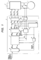
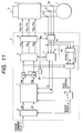
- Fig. 1 is a block diagram of a motor control system in which the synchronous motor 1 is driven with DC energy from a battery 2.
- a DC voltage of the battery 2 is inverted by an inverter 3 into three phase AC voltage which is applied to the synchronous motor 1.
- the applied voltage is determined by a controller 4 after performing the following calculation.
- a current command value generating unit 6 d-axis current command value idr and q-axis current command value iqr are determined with respect to a torque command value ⁇ r to be generated by the motor 1.
- d-axis designates the direction of magnetic pole position (magnetic fluxes) and q-axis designates the direction electrically orthogonal to the d-axis and with both of which d-q axis coordinate system is constituted.
- the ratio of idr and iqr can be varied under the condition of the same motor speed ⁇ and the same motor torque ⁇ being generated, although motor loss thereof varies. Therefore, when a motor speed ⁇ is inputted to the current command value generating unit 6, optimum idr and iqr which show a minimum motor loss with respect to a torque command value ⁇ r are designed to be outputted. Further, the motor speed w is detected in a speed detection unit 13 based on a variation amount of magnetic pole position ⁇ which will be explained later.
- the object of the present embodiment is to detect the phase ⁇ of the magnetic pole (hereinbelow called as magnetic pole position ⁇ ) from a current. If d-axis current and q-axis current can be controlled in an alignment with the command values, the synchronous motor 1 can generate a torque to meet with the command value ⁇ r. Further, the torque command value ⁇ r is either commanded directly as illustrated or may be commanded from a speed control calculation circuit (not shown).
- U phase current iu and V phase current iv detected by current sensors 5u and 5v are sampled in a current detection unit 10 at the timing of current detection pulses pd which will be explained later, and are converted into d-axis current id and q-axis current iq in d-q axis coordinate system at a coordinate conversion unit 11.
- currents detected in the current detection unit 10 are two phase currents iu and iv for U and V phases, because current iw can be determined from iu and iv, the detection of W phase current iw is omitted.
- the present invention is of course applicable when all of the three phase currents are detected.
- a current control unit 7 d-axis current deviation between d-axis current command value idr and d-axis current id and q-axis current deviation between q-axis current command value iqr and q-axis current iq are calculated, and d-axis voltage command value Vds and q-axis voltage command value Vqs for the respective current deviation are obtained through proportion and integration control calculation. Further, as a control method of compensating counter electromotive force a method of performing a noninterfering control making use of motor speed ⁇ has also been proposed.
- phase voltage command value Vus, Vvs and Vws for the static coordinate system are calculated according to magnetic pole position ⁇ .
- the three phase voltage command values are respectively added to detection use voltage command values Vup, Vvp and Vwp outputted from a magnetic pole position detection unit 12 which will be explained later, and are inputted to a PWM signal generating unit 9.
- PWM signal generating unit 9 three phase PWM pulses Pup, Pvp, Pwp, Pun, Pvn and Pwn are outputted to the inverter 3. Thereby, a voltage to be applied to the synchronous motor 1 is determined.
- the PWM pulses Pup, Pvp and Pwp between times t(2n) and t(2n+2) show respectively symmetric shapes with respect to time t(2n+1), therefore, the average values of the applied voltages for the respective phase from time t(2n) to time t(2n+2) are equal to those from time t(2n+1) to time t(2n+2).
- the magnetic pole position detection unit 12 which is one of important elements in Fig. 1 embodiment will be explained.
- the magnetic pole position detection unit 12 is inputted of the U phase current iu and the V phase current iv and output the detection use voltage command values Vup, Vvp and Vwp according to flowchart as shown in Fig. 4 as well as calculates the magnetic pole position ⁇ based on iu and iv.
- a processing method performed in the magnetic pole position detection unit 12 will be explained with reference to Fig. 4.
- step 101 as detection use voltage command values Vup(2n), Vvp(2n) and Vwp(2n) from time t(2n) to time t(2n+1), -Vus(2n), -Vvs(2n) and -Vws(2n) are outputted (wherein n is an integer). It is designed that at time t(2n) these values are automatically set and the voltage command values Vur, Vvr and Vwr for respective phases from time t(2n) to time t(2n+1) assume respectively 0. More specifically, the voltage command values in time periods t(2n) ⁇ t(2n+1) and t(2n+2) ⁇ t(2n+3) in the time chart as shown in Fig.
- step 103 currents iu(2n) and iv(2n) at time t(2n) are inputted.
- step 104 in synchronism with the leading edge of current detection pulses Pd which are generated at times t(2n) and t(2n+2), the detected currents are inputted.
- step 104 as the detection use voltage command values Vup(2n+1), Vvp(2n+1) and Vwp(2n+1) from time t(2n+1) to time t(2n+2), Vus(2n), Vvs(2n) and Vws(2n) are respectively outputted.
- Vup(2n+1), Vvp(2n+1) and Vwp(2n+1) are respectively outputted.
- the voltage command values in the time period t(2n+1) ⁇ t(2n+2) are respectively 2Vus(2n), 2Vvs(2n) and 2Vws(2n).
- average values of the voltage command values in the time period t(2n) ⁇ t(2n+2) assume Vus( 2n), Vvs(2n) and Vws(2n), and it is obtained that although the phases of the PWM pulses Pup, Pvp and Pwp vary from those in Fig. 2, but the pulse widths thereof are equal to those in Fig. 2. Namely, it is equivalent that a control of shifting phases of the PWM pulses is performed.
- the present embodiment shows a characteristic that no substantial influence is affected to the current control performance. Further, there was a problem conventionally that when detection use AC voltage is applied, noises are generated, however, since the detection use voltage command values are controlled for every half cycle of the carrier waves in synchronism therewith, the present embodiment shows a characteristic that no noises exceeding those caused by the normal PWM switching are generated.
- step 106 currents iu(2n+1) and iv(2n+1) at time t(2n+1) are inputted. Subsequently, at step 107 variation amounts of respective phase currents iu(2n+ 1)-iu(2n), iv(2n+1)-iv(2n), namely current difference values ⁇ iu(2n) and ⁇ iv(2n) from time t(2n) to time (2n+1) are determined. At the subsequent step 108, phase ⁇ q of the current difference vector ⁇ i(2n) is obtained from the current difference values ⁇ iu(2n) and ⁇ iv(2n).
- the applied voltages at time period t(2n) ⁇ t(2n+1) are the same for the respective phases, in that assume zero voltage vector state.
- a current difference vector ⁇ i(2n) of the synchronous motor 1 varies by its counter electromotive force
- the phase of the current difference vector ⁇ i(2n) assumes in negative direction in q-axis. Accordingly, the phase advanced by ⁇ /2 [rad] with respect to the phase ⁇ q of the current difference vector ⁇ i corresponds to the magnetic pole position, therefore, at step 109, the magnetic pole position ⁇ is determined by adding ⁇ /2 [rad] to the phase ⁇ q.
- the magnetic pole position detection can be realized only with the current changes in the half cycle of the carrier waves, therefore, the advantages that the magnetic pole position is rapidly detected without increasing noises. Further, it is unnecessary to use motor parameters including those of a synchronous motor having a salient pole characteristic, therefore, a further advantage that the magnetic pole position can be detected further accurately. Still further, when it is required to take into account of a dead time, the applied voltage can be adjusted so to assume zero voltage vector depending on the current directions of the respective phases.
- Fig. 5 is a modification of the magnetic pole position detection unit 12 which is effective when a synchronous motor 1 has an inverted salient pole characteristic (which implies that d-axis inductance is smaller than q-axis inductance).
- the magnetic pole position detection unit 12 as shown in Fig. 5 is constituted by a current difference calculation unit 14, a current difference difference vector phase calculation unit 15, a magnetic pole position estimation unit 16 and a detection use voltage generation unit 17.
- the detection use voltage command values Vup(2n), Vvp(2n) and Vwp(2n) from time t(2n) to time t(2n+1) are calculated according to the following equations (1) ⁇ (3) and the calculation results are outputted therefrom;
- Vup(2n) V0cos( ⁇ vp(2n))
- Vvp(2n) V0cos( ⁇ vp(2n)+2 ⁇ /3)
- Vwp(2n) V0cos( ⁇ vp(2n)+4 ⁇ /3) wherein, ⁇ vp(2n) is an output at time t(2n) from the magnetic pole position estimation unit 16.
- the vector phase of the detection use voltage command value is ⁇ vp(2n).
- the detection use voltage command values Vup(2n+1), Vvp( 2n+1) and Vwp(2n+1) from time t(2n+1) to time t(2n+2) are calculated according to the following equations (4) ⁇ (6) and the calculation results are outputted from the detection use voltage generation unit 17;
- Vup(2n+1) V0cos( ⁇ vp(2n)+ ⁇ )
- Vvp(2n+1) V0cos( ⁇ vp(2n)+5 ⁇ /3)
- Vwp(2n+1) V0cos( ⁇ vp(2n)+ ⁇ /3)
- the vector phase of the detection use voltage command value at this instance is ⁇ vp(2n)+ ⁇ , namely directs to the opposite direction as the vector phase of the detection use voltage command value from time t(2n) to time t(2n+1).
- current difference values ⁇ iu(2n) and ⁇ iv(2n) from time 2(2n) to time t(2n+1) are respectively calculated from the currents iu(2n) and iv(2n) at time t(2n) and the currents iu(2n+1) and iv(2n+1) at time t(2n+1), and a current difference vector ⁇ ia(2n) is determined according to these calculated values.
- current difference values ⁇ iu(2n+1) and ⁇ iv(2n+1) from time t(2n+1) to time t(2n+2) are calculated from currents iu(2n+1) and iv(2n+1) at time t(2n+1) and currents iu(2n+2) and iv(2n+2) at time t(2n+2) and the current difference vector ⁇ ib(2n+1) is determined according to these calculated values.
- the difference between the current difference vector ⁇ ib(2n+1) and the current difference vector ⁇ ia(2n) is the current difference difference vector ⁇ i(2n), and its phase ⁇ ip(2n) is calculated in the current difference difference vector phase calculation unit 15. It is to be noted that both the current difference vector and the current difference difference vector are values in the static coordinate system of which importance will be explained later.
- the magnetic pole position estimation unit 16 performs a control so as to make the vector phase ⁇ vp(2n) of the detection use voltage command value come close to the phase ⁇ ip(2n) of the current difference difference vector ⁇ i(2n).
- the phase ⁇ vp assumes d-axis, namely corresponds to the magnetic pole position ⁇ . Further, if the phase of d-axis varies more than several times during one cycle of the carrier waves (namely, in a case that the motor speed ⁇ is high), a control of correcting the phase depending on motor speed ⁇ is performed.
- Fig. 6A shows the state of current difference vector when only the three phase voltage command values Vus, Vvs and Vws outputted from the coordinate conversion unit 8 are applied to the synchronous motor 1, in that the voltage vector Vs(2n) from time t(2n) to time t(2n+2) corresponds to the three phase voltage command values Vus, Vvs and Vws.
- the current difference vector ⁇ i(2n) is a vector sum of a first current difference vector ⁇ ivs(2n), a second current difference vector ⁇ i ⁇ (2n) and a third current difference vector ⁇ ii(2n) of which component are respectively affected by the voltage vector Vs( 2n), the counter electromotive force vector -j ⁇ (2n) and the current vector i(2n).
- the second current differential vector ⁇ i ⁇ (2n) assumes the same phase as the counter electromotive force vector -j ⁇ (2n) regardless to whether or not the synchronous motor 1 shows a salient pole characteristic (including a reverse salient pole characteristic).
- the third current difference vector ⁇ ii(2n) is small in comparison with other current difference vectors and can be assumed as 0.
- the phase of the voltage vector Vs(2n) is neither directed to d-axis direction nor to q-axis direction, the phase of the first current differential vector ⁇ ivs(2n) does not coincide with the phase of the voltage vector Vs(2n) due to the salient pole characteristic of the synchronous motor 1.
- the current difference vector ⁇ i(2n) is affected by the voltage vector Vs( 2n) and the counter electromotive force vector -j ⁇ (2n), it is difficult to detect the magnetic pole position under this condition.
- Va(2n) representing a vector sum of the voltage vector Vs(2n) and the detection use voltage vector Vp(2n) is applied as shown in the vector diagram in Fig. 6B.
- the detected current difference vector ⁇ ia(2n) represents the vector sum of the current difference vector ⁇ ivp(2n) induced by the detection use voltage vector Vp(2n) and the current difference vector ⁇ i( 2n) as shown in Fig. 6A.
- Vb(2n+1) representing a vector sum of the voltage vector Vs(2n) and the detection use voltage vector Vp(2n+1) is applied as shown in Fig. 6C.
- the detected current difference vector ⁇ ib(2n+1) represents a vector sum of the current difference vector ⁇ ivp(2n+1) induced by the detection use voltage vector Vp(2n+1) and the current difference vector ⁇ i(2n+1) as shown in Fig. 6A.
- ⁇ i(2n+1) in Fig. 6C substantially coincides with ⁇ i(2n) in Fig. 6B.
- ⁇ ivp(2n) is a component induced by applying the detection use voltage vector Vp(2n).
- Vp(2n) and Aivp(2n) are respectively ⁇ vp(2n) and ⁇ ip(2n).
- ⁇ vp(2n) coincides with ⁇ ip(2n).
- ⁇ vp(2n) does not coincide with ⁇ ip(2n)
- ⁇ i(2n) (herein, indicated as 2 ⁇ ivp) is placed closer to d-axis than Vp(2n) as shown in Fig. 6D. Therefore, as explained in connection with the magnetic pole position estimation unit 16 as shown in Fig. 5, when the control of shifting ⁇ vp(2n) close to ⁇ ip(2n) is performed, the ⁇ vp(2n) stabilizes at d-axis. Further, whether positive or negative direction in d-axis can be estimated with reference to the counter electromotive force direction.
- a torque control or a speed control of the synchronous motor having an inverted salient pole characteristic can be performed from a standstill condition to a high speed rotation with no magnetic pole position sensor. Moreover, since the magnetic pole position can be detected within one cycle of the carrier waves, it is possible to obtain substantially the same degree of response characteristic as when a magnetic pole position sensor is installed. Further, with regard to a synchronous motor having a salient pole characteristic other than the inverted salient pole characteristic the sensorless control can be performed on the same principle.
- Fig. 7 is another embodiment of the synchronous motor control which permits to select one of a plurality of methods of detecting a magnetic pole position with no magnetic pole position sensor depending on motor speed ⁇ .
- the overall motor control structure is the same as Fig. 1 embodiment, however, the structure of the magnetic pole position detection unit 12 is modified from those in Figs. 1 and 5.
- Fig. 7 shows a block diagram of the magnetic pole position detection unit 12 which is constituted by a current difference calculation unit 14, a first magnetic pole position detection unit 19, a second magnetic pole position detection unit 20, a third magnetic pole position detection unit 21 and a calculation method change-over unit 18.
- the current difference calculation unit 14 performs the calculation as explained in Fig. 5 modification.
- the first magnetic pole position detection unit 19 the calculation as explained in connection with Fig. 5 embodiment is performed.
- the principle of magnetic pole position estimation by this calculation makes use of the current variation in relation to the salient pole characteristic (or the inverted salient pole characteristic) of the synchronous motor 1, the magnetic pole position detection can be performed from the standstill condition to a medium speed region of the synchronous motor with this calculation method.
- the second magnetic pole position detection unit 20 relates to a method of extracting the current difference vector due to the counter electromotive force from information on the applied voltage.
- the present method is effective for a motor speed range from a medium speed to a high speed.
- the third magnetic pole position detection unit 21 relates to an estimation method which makes use of a current difference vector caused by magnetic flux rotation without varying the applied voltage, the present method is particularly effective for magnetic pole position detection at the time of high speed rotation of the motor.
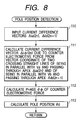
- the second magnetic pole position calculation unit 20 which is constituted by an in-short circuit current difference phase calculation unit 22, a magnetic pole position estimation unit 23 and detection use voltage generation unit 24.
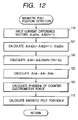
- the in-short circuit current difference phase calculation unit 22 calculates the phase of the counter electromotive force and estimates the magnetic pole position through performing the calculation as shown in Fig. 8 flowchart.
- current difference vectors ⁇ ia(2n) and ⁇ ib(2n+1) are inputted.
- ⁇ ia(2n) is the current difference vector, when a voltage Va(2n) is applied during interval t(2n) ⁇ t(2n+1).
- Va(2n) is a vector sum of the voltage vector Vs(2n) and the detection use voltage vector Vp(2n) of which relationship is shown in Fig. 9A.
- ⁇ ib(2n+1) is a current difference vector, when voltage Vb(2n) is applied during interval t(2n+1) ⁇ t(2n+2).
- the applied voltage Vb(2n+1) at this instance is a vector sum of the voltage vector Vs(2n) and the detection use voltage vector -Vp(2n) of which relationship is shown in Fig. 9B.
- a current difference vector ⁇ i ⁇ (2n) due to a counter electromotive force is calculated from a vector coordinate defined by two crossing straight lines, one running in parallel with the applied voltage Va(2n) and passing on the apex of ⁇ ia(2n) and the other running in parallel with the applied voltage Vb(2n+1) and passing on the apex of ⁇ ib(2n+1), of which implication will be explained with reference to Fig. 9C.
- a current difference component ⁇ iaq(2n) among the current difference vector ⁇ ia(2n) which is orthogonal to the applied voltage Va(2n) is hardly affected by the applied voltage Va(2n).
- ⁇ iaq(2n) can be treated mostly as a component of the current difference vector ⁇ i ⁇ (2n) due to the counter electromotive force.
- the current difference component ⁇ ibq(2n+1) among the current difference vector ⁇ ib(2n+1) which is orthogonal to the applied voltage Vb(2n+1) is hardly affected by the applied voltage Vb(2n+1), and can be treated mostly as a component of the current difference vector ⁇ i ⁇ (2n) due to the counter electromotive force.
- a component of the current difference vector ⁇ i ⁇ (2n) which is orthogonal to Va(2n) is ⁇ iaq(2n)
- another component of ⁇ i ⁇ (2n) which is orthogonal to Vb(2n+1) is ⁇ ibq(2n+1). Accordingly, when performing the calculation at step 111, the current difference vector ⁇ i ⁇ (2n) can be determined.
- the phase ⁇ of ⁇ i ⁇ (2n) is calculated, of which phase is the very phase of the counter electromotive force as has been explained above. Since the phase ⁇ of the vector ⁇ i ⁇ (2n) corresponds to q-axis (in negative direction) as shown in Fig.
- the magnetic pole position ⁇ d can be obtained by adding ⁇ /2 [rad] to this phase ⁇ of which calculation is performed at step 113.
- the magnetic pole position can be determined based on the counter electromotive force.
- the processings as shown in Fig. 8 are performed in view of the salient pole characteristic of which effect varies depending on the speed, thereby, a further accurate magnetic pole position detection can be realized.
- the magnetic pole position estimation unit 23 feeds back the magnetic pole position ⁇ vp which was determined by the processings performed until the last time, thereby, a filtering with respect to noises is performed.
- the detection use voltage generation unit 24 functions to output the detection use applied voltage Vp as shown in Figs. 9A and 9B, and determines Vp according to the magnetic pole position ⁇ vp and d-axis voltage command value and q-axis voltage command value outputted from the current control unit 7.
- Vp the detection use applied voltage
- the calculation is performed so that Vp directs to the direction orthogonal to the voltage vector Vs as shown in Figs. 9A through 9C, which is determined in a consideration that the absolute values of Va and Vb do not exceedingly increase.
- the third magnetic pole position detection unit 21 is a means for performing the magnetic pole position detection with a high accuracy when the motor speed ⁇ increases.
- the fundamental principle of the present invention is to detect a magnetic pole position from variation of current which is in synchronism with the carrier waves and since the time interval for the current variation used for the calculation is short (for example, one cycle time of the carrier waves), therefore, it is assumed that during the short time interval the variation of the magnetic pole position is very small. However, when the motor speed increases exceedingly high, it sometimes happens that the magnetic pole position varies more than 10° during the short time interval.
- the magnetic pole position is calculated by detecting the variation of the current difference vector due to variation of the position (phase) of the counter magnetomotive force without varying the applied voltage of which method is effective when the motor speed ⁇ is high, because it is unnecessary to increase the applied voltage.
- the third magnetic pole position detection unit 21 is constituted by an under flux rotation current difference phase calculation unit 25, a magnetic pole position estimation unit 26 and a detection use voltage generation unit 27.
- the detection use voltage generation unit 27, in practice, always outputs value 0.
- the under flux rotation current difference phase calculation unit 25 determines a difference between the current difference vectors ⁇ ia(2n) and ⁇ ib(2n+1), namely the current difference difference vector ⁇ i( 2n), of which calculation itself is identical to that performed in the current difference difference vector phase calculation unit 15. Since the detection use voltage Vup, Vvp and Vwp are always 0, the current difference difference vector ⁇ i(2n) will primarily be 0.
- an averaged magnetic pole position from time t(2n) to time t(2n+1) and an averaged magnetic pole position from time t(2n+1) to time t(2n+2) are different, therefore, average counter electromotive forces Vemf(2n) and Vemf(2n+1) at the two time intervals are different. Accordingly, due to a difference between Vemf(2n+1) and Vemf(2n), in that counter electromotive force difference vector ⁇ Vemf( 2n) the current difference difference vector ⁇ i(2n) can not assume 0, but shows a certain amount of vector.
- the direction of ⁇ emf(2n) is almost orthogonal to the direction of q-axis, in that in the direction of d-axis (in negative direction). Accordingly, the direction of ⁇ i(2n) also assumes the direction of ⁇ Vemf(2n), in that d-axis direction (in negative direction thereof) - ⁇ d. Through the calculation of the direction of the current difference difference vector ⁇ i(2n) in this way, - ⁇ d can be obtained.
- the magnetic position estimation unit 26 performs a noise processing by making use of the magnetic pole position ⁇ and - ⁇ d obtained by the last processings, and outputs a magnetic pole position ⁇ .
- the third magnetic pole position detection unit 21 estimates the magnetic pole position by making use of the current difference vector induced by the rotation of magnetic fluxes without varying the applied voltage of which method is particularly effective for the detection of the magnetic pole position at the time of high speed rotation of the synchronous motor.
- the calculation method change-over unit 18 estimates a motor speed ⁇ based on the magnetic pole position ⁇ (or ⁇ vp) obtained by the magnetic pole position estimation units and performs processing of selecting an optimum magnetic pole position estimation method in response to the estimated motor speed.
- the magnetic pole position can always be detected in a moment with a high accuracy over a motor speed range from 0 to its maximum speed, thereby, a motor control system having a high response and high performance control property can be provided. Further, when a current sensor having an accurate current detection and less noise property is used, the magnetic pole position can be estimated in a moment for every one cycle of the carrier waves, while eliminating the filtering processing at the magnetic pole position estimation units 23 and 26. Further, in the combination of the magnetic pole position detection methods to be changed-over, a further magnetic pole position detection method which will be explained later can be included.
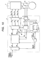
- Fig. 10 is still another embodiment showing a magnetic pole position detection method in which the calculation therefor is simplified.
- Primary differences of Fig. 10 embodiment from 1 and Fig. 5 embodiments are that the two current sensors are increased to three, the output Vp of the detection use voltage generation unit 28 is added to the d-axis voltage command, and the processing method in the magnetic pole position detection unit 12 is simplified.
- the W phase current iw can be determined from iu and iv, therefore, the detection of the W phase current iw can be omitted, however, in the present embodiment the W phase current iw is likely detected with a current sensor 5w.
- the detection use voltage generation unit 28 representing features of the present embodiment will be explained.
- the detection use applied voltage Vp is applied in positive and negative direction of an estimated d-axis in synchronism with the carrier waves. For this reason, in the detection use voltage generation unit 28 a process of adding the detection use applied voltage Vp of positive and negative values alternatively to the d-axis voltage Vds in response to the current detection pulses Pd.
- the magnetic pole position detection unit 12 is constituted by the current difference calculation unit 14 and the current difference difference vector phase calculation unit 15 which have been explained in connection with Fig. 5 embodiment.
- the current difference vector ⁇ ia(2n) during time from t(2n) to t(2n-1) and the current difference vector ⁇ ib(2n+1) during time from t(2n+1) to t(2n+2) are calculated respectively from the three phase currents iu, iv and iw, and are outputted to the current difference vector phase calculation unit 15.
- the current difference difference vector phase calculation unit 15 the current difference difference vector ⁇ i(2n) is determined from a difference between ⁇ ib(2n+1) and ⁇ ia(2n), and the phase ⁇ ip(2n) is calculated.
- the phase ⁇ ip(2n) of ⁇ i(2n), as it is, is assumed as the magnetic pole position and is outputted to the coordinate conversion units 8 and 11 and the speed detection unit 13 so as to constitute the control system.
- the phase ⁇ ip(2n) of the current difference difference vector ⁇ i(2n) is closer to the actual d-axis with respect to the estimated d-axis direction to which the detection use voltage Vp is applied.
- the magnetic pole position detection can be performed through a more simplified calculation than the other calculation methods, therefore, a motor control system with more low cost can be provided. Further, such as a noise removal use low pass filter and the magnetic pole position estimation unit 16 can be added to the magnetic pole position detection unit 12 in Fig. 10.
- a further embodiment as shown in Fig. 11 through Fig. 13 relates to a method of estimating a magnetic pole position by making use of a counter electromotive force and is different from the embodiment as shown in Fig. 7 through Fig. 9.
- Primary features of Fig. 11 embodiment is that a voltage gain setting unit 29 is provided and a different calculation method is used in a magnetic pole position estimation unit 30.
- a value of voltage gain Kp is either increased or decreased in response to the current detection pulses Pd. For example, during time from t(2n) to t(2n+1) Kp is set larger than 1 and during time from t(2n+1) to t(2n+2) Kp is set smaller than 1.
- d-axis voltage command value Vds and q-axis voltage command value Vqs respectively either increase or decrease depending on Kp.
- the voltage vector Va(2n) during time from t(2n) to t(2n+1) is in-phase with the voltage command vector Vs (vector sum of Vds and Vqs) and the absolute value thereof is larger than Vs
- the voltage vector Vb(2n+1) during time from t(2n+1) to t(2n+2) is in-phase with Vs and the absolute value thereof is smaller than Vs.
- an average value of Va(2n) and Vb(2n+1) can be set at Vs.
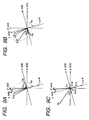
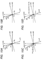
- the current difference vectors ⁇ ia(2n) and ⁇ ib(2n+1) in such exemplified instance are illustrated in Figs. 13A and 13B. These vectors are affected not only by the applied voltage vectors Va(2n) and Vb(2n+1) but also by the counter electromotive force (-j ⁇ ). Thus, the phase of the counter electromotive force is detected according to the method as shown in Fig. 12 flowchart.
- the magnetic pole position detection unit 12 as shown in Fig. 11 is constituted by the current difference calculation unit 14 and the magnetic pole position estimation unit 30.
- the current difference calculation unit 14 calculates the current difference vectors ⁇ ia(2n) and ⁇ ib(2n+1), and these values are inputted into the magnetic pole position estimation unit 30 where the calculation according to Fig. 12 flowchart is performed.
- the current difference difference vector ⁇ i(2n) representing the difference between ⁇ ia(2n) and ⁇ ib( 2n+1) is calculated at step 121.
- ⁇ i(2n) is a difference of current difference, an influence of the counter electromotive force can be eliminated, and which represents current difference vector determined by ⁇ Vb(2n+1)-Va(2n) ⁇ of which vector relationship is shown in Fig. 13C.
- ⁇ i( 2n)Vb/(Vb-Va) is calculated to determine the current difference vector ⁇ ibv(2n+1).
- the current difference vector ⁇ ibv(2n+1) is a current difference vector when Vb(2n+1) is applied under no counter electromotive force.
- a difference between ⁇ ib(2n+1) and ⁇ ibv(2n+1) and the counter electromotive force current difference vector ⁇ id are calculated.
- ⁇ ib( 2n+1) is a current difference vector affected by Vb(2n+1) and the counter electromotive force
- ⁇ ibv(2n+1) is a current difference vector affected only by Vb(2n+1)
- the difference ⁇ id ⁇ therebetween is a component affected by the counter electromotive force of which vector diagram is shown in Fig. 13D. Accordingly, through calculation of the phase ⁇ of the counter electromotive force current difference vector ⁇ i ⁇ at step 124 q-axis (negative direction thereof) can be determined.
- step 113 in Fig. 12 through adding ⁇ /2 [rad] to the phase ⁇ d-axis namely the magnetic pole position 6 is obtained.
- the magnetic pole position detection can be realized as well as through a correct drawing of vector diagram of the current different vector the phase of the counter electromotive force can be easily detected.
- Fig. 14 is a control block diagram showing a further embodiment in which the characteristic of the current control system is improved by correctly detecting the counter electromotive force.
- the present embodiment is directed to a motor control system including a magnetic pole position sensor 50 and is intended to realize a different object than that for the control systems with no magnetic pole sensors as has been explained. Therefore, the magnetic pole position ⁇ detected by the magnetic pole position sensor 50 is outputted such as to the coordinate conversion units 8 and 11 and to the speed detection unit 13 so as to use the motor control.
- Primary differences other than the above performed in Fig. 14 embodiment are those in the current control unit 7 and in a counter electromotive force detection unit 51.
- d-axis and q-axis components Vde and Vqe in the counter electromotive force are calculated from the three phase currents iu, iv and iw and the magnetic pole position ⁇ . These values are inputted into the current control unit 7 and are used for counter electromotive force compensation in the current control system, thereby, a current control characteristic such as at a time of sudden speed change can be improved.
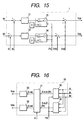
- Fig. 15 is a block diagram showing processing contents performed in the current control unit 7 wherein valid / invalid of the current control system is changed over in response to the current detection pulses Pd.
- a d-axis current control calculation unit 31 and a q-axis current control calculation unit 32 respectively feed back d-axis current and q-axis current for d-axis and q-axis current command values idr and iqr and perform control calculation so as to assume their current deviations zero.
- d-axis and q-axis change-over units 33 and 34 it is changed-over whether the calculation result of the d-axis and q-axis current control calculation units 31 and 32 is outputted or zero is outputted in response to the current detection pulses Pd. More specifically, during interval from time t(2n) to time t(2n+1) zero is outputted and during interval from time t(2n+1) to time t(2n+2) the current control calculation result is outputted. In other words, when seen the above from a point as a current control system only 1/2 voltage in average is outputted. Therefore, in this control system by doubling the normal gain of the current control system an equal current control characteristic can be ensured.
- the counter electromotive force detection unit 51 is constituted by an ⁇ -axis current difference detection unit 35, a ⁇ -axis current difference detection unit 36, a coordinate conversion unit 37, a d-axis counter electromotive force calculation unit 38 and a q-axis counter electromotive force calculation unit 39.
- the ⁇ -axis current difference detection unit 35 and the ⁇ -axis current difference detection unit 36 are inputted of three phase currents iu, iv and iw and output a current difference vector ⁇ ia(2n) during interval from time t(2n) to time t(2n+1), in that an ⁇ -axis component ⁇ ia ⁇ (2n) and a ⁇ -axis component ⁇ ia ⁇ (2n) in the current difference vector ⁇ ia(2n) are detected.
- Fig. 17 is a motor control system block diagram representing a further embodiment which improves the performance at a moment of motor speed sudden change in comparison with that of a conventional current control without using a magnetic pole position sensor.
- major differences are that the magnetic pole position sensor 50 is omitted, the detection of the magnetic pole position ⁇ and the counter electromotive force is performed at the magnetic pole position detection unit 12 and the compensation for the counter electromotive force is performed by applying to the respective phase voltages in the static coordinate system other than the current control unit 7.
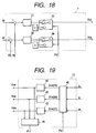
- the calculation method performed in the current control unit 7 in Fig. 17 is shown in block diagram in Fig. 18 which is substantially the same as with Fig. 15 embodiment and substantially the same calculation is performed therein. Only the difference of Fig.
- Fig. 19 shows a block diagram of the magnetic pole position detection unit 12 which performs an important process in the present embodiment.
- a current difference detection unit 40 respective phase current difference values ⁇ iu(2n), ⁇ iv(2n) and iw(2n) during interval from time t(2n) to time t(2n+1) are calculated in response to timing of the current detection pulses Pd. These values contain same information as in ⁇ iad(2n) and ⁇ ia ⁇ (2n) as shown in Fig. 16. Even in Fig.
- 17 system is constituted by a method of using a counter electromotive force, however, a method can be applied which permits both to detect the magnetic pole position by making use of the salient pole property (the inverted salient pole property) and to keep the current control property by the counter electromotive force estimation.
- the present invention is applicable to the synchronous motor having both a cylindrical type rotor and a rotor having a salient pole property. Further, other than the synchronous motor, the present invention is also applicable to a reluctance motor while making use of its salient pole property. Further, although in order to avoid complexing explanation of the embodiments, an explanation on a calculation of the magnetic pole position in view of influences that the motor rotor rotates during sampling is omitted, however, such calculation can, of course, be included to the present embodiments.
- the method of detecting the magnetic pole position for every one cycle of the carrier waves has been explained, however, the detection can be realized in the same manner such as with amethod of detecting the magnetic pole position by using current variation of one cycle in every plurality of cycles of the carrier waves and a method of detecting the magnetic pole position based on current variation for a unit of a plurality of cycles of the carrier waves.
- the present embodiments can be applied to such as an electric car and a hybrid car, besides when the present embodiments are applied to a magnet motor to which a sensorless control is now effected through an inverter control of 120° current conduction method, a sensorless system of no torque ripple and low noises can be provided through an inverter control of 180° current conduction method.
- the magnetic pole position can be detected on-line while performing the usual PWM control, thereby, a synchronous motor drive system with low noises and excellent torque control property can be provided with low cost without using a magnetic pole position sensor measuring a rotating position mechanically.
Landscapes
- Engineering & Computer Science (AREA)
- Power Engineering (AREA)
- Control Of Motors That Do Not Use Commutators (AREA)
- Control Of Ac Motors In General (AREA)
Applications Claiming Priority (2)
| Application Number | Priority Date | Filing Date | Title |
|---|---|---|---|
| JP34294399 | 1999-12-02 | ||
| JP34294399A JP3454212B2 (ja) | 1999-12-02 | 1999-12-02 | モータ制御装置 |
Publications (4)
| Publication Number | Publication Date |
|---|---|
| EP1107448A2 true EP1107448A2 (de) | 2001-06-13 |
| EP1107448A3 EP1107448A3 (de) | 2003-01-02 |
| EP1107448B1 EP1107448B1 (de) | 2009-02-11 |
| EP1107448B8 EP1107448B8 (de) | 2009-04-08 |
Family
ID=18357725
Family Applications (1)
| Application Number | Title | Priority Date | Filing Date |
|---|---|---|---|
| EP00122392A Expired - Lifetime EP1107448B8 (de) | 1999-12-02 | 2000-10-25 | Motorsteuerungsvorrichtung |
Country Status (4)
| Country | Link |
|---|---|
| US (1) | US6555988B2 (de) |
| EP (1) | EP1107448B8 (de) |
| JP (1) | JP3454212B2 (de) |
| DE (1) | DE60041529D1 (de) |
Cited By (8)
| Publication number | Priority date | Publication date | Assignee | Title |
|---|---|---|---|---|
| DE10226974A1 (de) * | 2002-06-17 | 2004-01-08 | Siemens Ag | Verfahren und Vorrichtung zur Bestimmung einer Rotorlage einer feldorientiert betriebenen Drehfeldmaschine ohne mechanischen Sensor |
| EP1280266A3 (de) * | 2001-07-24 | 2004-04-21 | Hitachi, Ltd. | Motorsteuerung |
| FR2855679A1 (fr) * | 2003-06-02 | 2004-12-03 | Alstom | Procede et systeme de regulation du couple electromagnetique instantane, et support d'enregistrement pour la mise en oeuvre du procede |
| EP1492223A4 (de) * | 2002-03-22 | 2005-12-14 | Matsushita Electric Industrial Co Ltd | Synchron-reluktanzmotorsteuereinrichtung |
| EP1401093A3 (de) * | 2002-09-18 | 2006-01-11 | Hitachi, Ltd. | Verfahren zur Motorregelung ohne Positionssensor und Vorrichtung |
| CN1333518C (zh) * | 2005-12-30 | 2007-08-22 | 上海新时达电气有限公司 | 测量永磁同步电机的初始转子位置方法 |
| FR3003415A1 (fr) * | 2013-03-13 | 2014-09-19 | Bosch Gmbh Robert | Installation et procede de commande d'une machine a champ tournant |
| EP4020793A1 (de) * | 2020-12-23 | 2022-06-29 | Schneider Toshiba Inverter Europe SAS | Drehzahlvariabler antrieb für die sensorlose pwm-steuerung eines wechselstrommotors mit stromrauschunterdrückung |
Families Citing this family (78)
| Publication number | Priority date | Publication date | Assignee | Title |
|---|---|---|---|---|
| GB2347283B (en) * | 1998-10-30 | 2003-03-12 | Toshiba Kk | Synchronous motor controller |
| JP3678151B2 (ja) * | 2001-01-11 | 2005-08-03 | 日産自動車株式会社 | 電気車両の地絡検出装置 |
| JP3840905B2 (ja) * | 2001-03-08 | 2006-11-01 | 株式会社日立製作所 | 同期電動機の駆動装置 |
| JP3695342B2 (ja) * | 2001-04-11 | 2005-09-14 | 株式会社日立製作所 | 電動機の制御装置 |
| EP1411629A1 (de) * | 2001-07-04 | 2004-04-21 | Kabushiki Kaisha Yaskawa Denki | Verfahren und einrichtung zur steuerung von strömen eines synchronen motors |
| KR100421376B1 (ko) * | 2001-07-10 | 2004-03-09 | 엘지전자 주식회사 | 동기 릴럭턴스 모터의 회전 속도 제어장치 |
| JP4075338B2 (ja) * | 2001-07-18 | 2008-04-16 | 株式会社豊田自動織機 | 電動圧縮機の制御方法 |
| JP4665360B2 (ja) * | 2001-08-06 | 2011-04-06 | 株式会社安川電機 | 電動機制御装置 |
| JP2003079200A (ja) * | 2001-09-04 | 2003-03-14 | Hitachi Ltd | 電動機駆動システム |
| JP3501370B2 (ja) * | 2001-09-04 | 2004-03-02 | 株式会社デンソー | 同期モータの制御方法および制御装置 |
| DE10206191B4 (de) * | 2001-11-27 | 2006-02-02 | Siemens Ag | Verfahren zur feldorientierten Regelung einer permanenterregten Synchronmaschine mit Reluktanzmoment |
| JP3692085B2 (ja) * | 2002-02-21 | 2005-09-07 | 株式会社東芝 | モータ制御方法及び装置 |
| JP4059039B2 (ja) * | 2002-08-30 | 2008-03-12 | 株式会社安川電機 | 同期電動機の制御装置 |
| JP2004343833A (ja) * | 2003-05-13 | 2004-12-02 | Toshiba Corp | モータ制御装置 |
| JP4619040B2 (ja) * | 2004-05-14 | 2011-01-26 | アイシン・エィ・ダブリュ株式会社 | 電動駆動制御装置、電動駆動制御方法及びプログラム |
| JP4398312B2 (ja) * | 2004-07-06 | 2010-01-13 | 矢崎総業株式会社 | 半導体スイッチの制御装置 |
| CA2512374A1 (en) * | 2004-08-23 | 2006-02-23 | Agile Systems Inc. | System and method for sensor less magnetic field control of a motor |
| US6967461B1 (en) * | 2004-08-31 | 2005-11-22 | Hamilton Sundstrand Corporation | North-south pole determination for carrier injection sensorless position sensing systems |
| JP4592385B2 (ja) * | 2004-10-27 | 2010-12-01 | 株式会社東芝 | 同期機の制御装置 |
| US7211984B2 (en) * | 2004-11-09 | 2007-05-01 | General Motors Corporation | Start-up and restart of interior permanent magnet machines |
| EP1834402A1 (de) * | 2005-01-07 | 2007-09-19 | Ronald De Four | Selbststartendes verfahren und vorrichtung zur sensorlosen kommutierung von bürstenlosen gleichstrommotoren |
| KR100657489B1 (ko) * | 2005-03-08 | 2006-12-19 | 엘지전자 주식회사 | 센서가 부착되지 않은 모터의 기동 판정 방법 및 장치 |
| US7652441B2 (en) * | 2005-07-01 | 2010-01-26 | International Rectifier Corporation | Method and system for starting a sensorless motor |
| US7256564B2 (en) * | 2005-09-29 | 2007-08-14 | Agile Systems Inc. | System and method for attenuating noise associated with a back electromotive force signal in a motor |
| US7477034B2 (en) * | 2005-09-29 | 2009-01-13 | Agile Systems Inc. | System and method for commutating a motor using back electromotive force signals |
| US7592761B2 (en) * | 2005-09-29 | 2009-09-22 | Agile Systems Inc. | System and method for starting and operating a motor |
| US7288911B2 (en) * | 2005-09-29 | 2007-10-30 | Agile Systems Inc. | System and method for commutating a motor |
| US7279860B2 (en) * | 2005-09-29 | 2007-10-09 | Agile Systems Inc. | System and method for evaluating back electromotive force in a motor |
| US20070069677A1 (en) * | 2005-09-29 | 2007-03-29 | Mackay David K | System and method for applying energy to a motor |
| JP4674525B2 (ja) * | 2005-10-13 | 2011-04-20 | 株式会社デンソー | 磁極位置推定方法及びモータ制御装置 |
| JP4657892B2 (ja) * | 2005-11-04 | 2011-03-23 | 本田技研工業株式会社 | Dcブラシレスモータのロータ角度推定装置およびロータ角度推定方法 |
| JP4675766B2 (ja) * | 2005-12-12 | 2011-04-27 | 本田技研工業株式会社 | 電動機の制御装置 |
| DE102006046638A1 (de) * | 2005-12-15 | 2007-06-21 | Strothmann, Rolf, Dr.rer.nat. | Vorrichtung und Verfahren zur Ermittlung der Drehlage des Rotors einer elektrischen Maschine |
| DE112006003675T5 (de) * | 2006-01-17 | 2008-12-18 | Kabushiki Kaisha Yaskawa Denki, Kitakyushu-Shi | Einphasen-Ausgangswechselrichter und Ausgangsstrom-Erfassungsverfahren |
| JP4835845B2 (ja) * | 2006-07-11 | 2011-12-14 | 株式会社ジェイテクト | ブラシレスモータ用制御装置 |
| US7932692B2 (en) | 2006-11-13 | 2011-04-26 | Denso Corporation | Control system for rotary electric machine with salient structure |
| JP4279886B2 (ja) * | 2007-02-28 | 2009-06-17 | 株式会社日立製作所 | 同期モータ駆動装置および方法 |
| JP5176420B2 (ja) * | 2007-08-02 | 2013-04-03 | 株式会社ジェイテクト | ブラシレスモータのセンサレス制御装置 |
| JP4270316B2 (ja) * | 2007-10-24 | 2009-05-27 | ダイキン工業株式会社 | 電力変換装置 |
| JP4508236B2 (ja) * | 2007-12-19 | 2010-07-21 | 株式会社デンソー | 回転機の制御装置 |
| KR101561922B1 (ko) * | 2007-12-21 | 2015-10-20 | 엘지전자 주식회사 | 공기조화기의 전동기 제어방법 |
| JP5175569B2 (ja) * | 2008-02-07 | 2013-04-03 | ルネサスエレクトロニクス株式会社 | 同期電動機の駆動システム |
| GB0803279D0 (en) | 2008-02-22 | 2008-04-02 | Univ Gent | Sensorless control of salient pole machines |
| JP2009268218A (ja) * | 2008-04-24 | 2009-11-12 | Juki Corp | 多軸モータ制御システム |
| DE102008041856B4 (de) * | 2008-09-08 | 2016-06-09 | Robert Bosch Gmbh | Lageerkennung eines Rotors einer elektronisch kommutierten elektrischen Maschine |
| EP2192413A1 (de) * | 2008-12-01 | 2010-06-02 | ABB Oy | Verfahren und Vorrichtung zur Bestimmung der Drehzahl eines elektrischen Motors |
| JP5396876B2 (ja) | 2009-01-21 | 2014-01-22 | 株式会社安川電機 | 交流電動機の制御装置 |
| JP5271409B2 (ja) * | 2009-03-25 | 2013-08-21 | 三菱電機株式会社 | 回転電機の制御装置 |
| US8294413B2 (en) * | 2010-01-05 | 2012-10-23 | GM Global Technology Operations LLC | Induction motor control systems and methods |
| CN103098366B (zh) * | 2010-07-12 | 2016-05-18 | 松下电器产业株式会社 | 相位偏移检测装置、马达驱动装置、无刷马达以及相位偏移检测方法 |
| TW201212525A (en) * | 2010-09-15 | 2012-03-16 | Fitipower Integrated Tech Inc | Control method for voice coil motor control method and lens focusing system |
| CN102468803A (zh) * | 2010-11-05 | 2012-05-23 | 天钰科技股份有限公司 | 音圈电机的控制方法及镜头对焦系统 |
| JP5348153B2 (ja) | 2011-02-14 | 2013-11-20 | 株式会社デンソー | 回転機の制御装置 |
| JP5321614B2 (ja) | 2011-02-28 | 2013-10-23 | 株式会社デンソー | 回転機の制御装置 |
| FR2972583B1 (fr) * | 2011-03-11 | 2013-03-01 | Schneider Toshiba Inverter | Procede de commande mis en oeuvre dans un convertisseur de puissance pour identifier des parametres lies a la saturation magnetique d'un moteur electrique |
| US8963459B2 (en) * | 2011-09-07 | 2015-02-24 | Samsung Techwin Co., Ltd. | Method and apparatus for driving alternating-current motor |
| JP5534252B2 (ja) | 2012-02-22 | 2014-06-25 | 株式会社デンソー | 交流電動機の制御装置 |
| JP5488845B2 (ja) | 2012-02-22 | 2014-05-14 | 株式会社デンソー | 交流電動機の制御装置 |
| JP5621998B2 (ja) * | 2012-02-22 | 2014-11-12 | 株式会社デンソー | 交流電動機の制御装置 |
| JP5598767B2 (ja) | 2012-02-22 | 2014-10-01 | 株式会社デンソー | 交流電動機の制御装置 |
| GB2503039B (en) * | 2012-06-15 | 2020-05-27 | Danfoss Drives As | Method for controlling a synchronous reluctance electric motor |
| GB2503040B (en) * | 2012-06-15 | 2020-05-06 | Danfoss Drives As | Variable torque angle for electric motor |
| JP6194466B2 (ja) * | 2013-04-11 | 2017-09-13 | パナソニックIpマネジメント株式会社 | モータ駆動装置 |
| JP6208005B2 (ja) * | 2013-12-25 | 2017-10-04 | 株式会社東芝 | 電動機の磁極位置推定装置、インバータ装置及び電動機システム |
| US9571019B2 (en) | 2014-09-19 | 2017-02-14 | Seiko Epson Corporation | Control device of motor, electronic apparatus, recording apparatus, robot, and control method of motor |
| CN104811095B (zh) * | 2015-04-28 | 2018-03-27 | 广东美的暖通设备有限公司 | 电动机的启动控制方法、装置和空调器 |
| TWI558090B (zh) * | 2015-07-24 | 2016-11-11 | 茂達電子股份有限公司 | 用於消除直流馬達內轉子之充磁誤差的控制裝置及其方法 |
| US9995119B2 (en) | 2015-11-16 | 2018-06-12 | Ge Oil & Gas Esp, Inc. | Electric submersible pumping system with permanent magnet motor |
| JP6914787B2 (ja) | 2017-09-20 | 2021-08-04 | 株式会社東芝 | モータ制御用集積回路 |
| JP2020048337A (ja) * | 2018-09-19 | 2020-03-26 | 株式会社東芝 | ロータ位置推定装置、モータ制御装置及びプログラム |
| JP7070330B2 (ja) | 2018-10-26 | 2022-05-18 | 株式会社デンソー | 回転電機の制御装置 |
| US11075597B2 (en) | 2018-12-04 | 2021-07-27 | Aisin Seiki Kabushiki Kaisha | Motor control device |
| CN110146211B (zh) * | 2019-05-20 | 2020-09-11 | 北京理工大学 | 一种基于电机驱动电流的电动缸输出力检测方法 |
| KR102675527B1 (ko) | 2019-11-28 | 2024-06-13 | 가부시키가이샤 도요다 지도숏키 | 전동기의 제어 장치 |
| JP7259811B2 (ja) * | 2019-11-28 | 2023-04-18 | 株式会社豊田自動織機 | 電動機の制御装置 |
| CN110995095B (zh) * | 2020-03-05 | 2020-06-05 | 中国科学院宁波材料技术与工程研究所 | 无位置传感器的永磁同步电机控制方法及汽车动力系统 |
| WO2022110107A1 (zh) * | 2020-11-30 | 2022-06-02 | 华为技术有限公司 | 角度获取方法及相关装置 |
| DE102024200726A1 (de) * | 2024-01-26 | 2025-07-31 | Robert Bosch Gesellschaft mit beschränkter Haftung | Verfahren zum Betreiben einer Antriebseinheit eines Nabenantriebs eines Elektrofahrrads |
Family Cites Families (14)
| Publication number | Priority date | Publication date | Assignee | Title |
|---|---|---|---|---|
| AT399602B (de) * | 1992-04-07 | 1995-06-26 | Elin Energieanwendung | Verfahren und schaltungsanordnung zur rotorlage- bestimmung und zur momentenaufbringung an einer über einen umrichter gespeisten reluktanzmaschine |
| AT397440B (de) * | 1991-04-19 | 1994-04-25 | Elin Energieanwendung | Verfahren und schaltungsanordnung zur sensorlosen drehwinkelerfassung einer vorzugsweise permanentmagneterregten, über einen stromrichter gespeisten synchronmaschine |
| JP3312472B2 (ja) | 1994-03-01 | 2002-08-05 | 富士電機株式会社 | 電動機の磁極位置検出装置 |
| US5652495A (en) * | 1994-05-25 | 1997-07-29 | Matsushita Electric Industrial Co., Ltd. | Controller for permanent magnet synchronous motor |
| US5448149A (en) * | 1994-06-20 | 1995-09-05 | Texas A&M University | Indirect rotor position sensor for a sinusoidal synchronous reluctance machine |
| JP3312520B2 (ja) | 1995-01-24 | 2002-08-12 | 富士電機株式会社 | 電動機の磁極位置検出装置 |
| US5903129A (en) * | 1995-02-10 | 1999-05-11 | Denso Corporation | Method and apparatus for sensor-less control of permanent magnet synchronous motor |
| US5821713A (en) * | 1995-09-11 | 1998-10-13 | Advanced Motion Controls, Inc. | Commutation position detection system and method |
| EP0792537A4 (de) * | 1995-09-20 | 1998-11-18 | Georgia Tech Res Inst | Verfahren und vorrichtung zur regelung eines geschalteten reluktanz-motors |
| JP3401155B2 (ja) * | 1997-02-14 | 2003-04-28 | 株式会社日立製作所 | 同期電動機制御装置および電気車 |
| JP3168953B2 (ja) | 1997-08-21 | 2001-05-21 | トヨタ自動車株式会社 | 電気角検出装置およびその設計方法 |
| JP3168967B2 (ja) | 1997-09-12 | 2001-05-21 | トヨタ自動車株式会社 | 電気角検出装置および方法、並びにモータ制御装置 |
| US6281656B1 (en) * | 1998-09-30 | 2001-08-28 | Hitachi, Ltd. | Synchronous motor control device electric motor vehicle control device and method of controlling synchronous motor |
| US6153956A (en) * | 1999-09-16 | 2000-11-28 | A. O. Smith Corporation | Switched reluctance position sensing |
-
1999
- 1999-12-02 JP JP34294399A patent/JP3454212B2/ja not_active Expired - Lifetime
-
2000
- 2000-10-25 EP EP00122392A patent/EP1107448B8/de not_active Expired - Lifetime
- 2000-10-25 DE DE60041529T patent/DE60041529D1/de not_active Expired - Lifetime
- 2000-12-01 US US09/726,595 patent/US6555988B2/en not_active Expired - Lifetime
Cited By (12)
| Publication number | Priority date | Publication date | Assignee | Title |
|---|---|---|---|---|
| EP1280266A3 (de) * | 2001-07-24 | 2004-04-21 | Hitachi, Ltd. | Motorsteuerung |
| US6844697B2 (en) | 2001-07-24 | 2005-01-18 | Hitachi, Ltd. | Motor controller |
| EP1492223A4 (de) * | 2002-03-22 | 2005-12-14 | Matsushita Electric Industrial Co Ltd | Synchron-reluktanzmotorsteuereinrichtung |
| DE10226974A1 (de) * | 2002-06-17 | 2004-01-08 | Siemens Ag | Verfahren und Vorrichtung zur Bestimmung einer Rotorlage einer feldorientiert betriebenen Drehfeldmaschine ohne mechanischen Sensor |
| EP1401093A3 (de) * | 2002-09-18 | 2006-01-11 | Hitachi, Ltd. | Verfahren zur Motorregelung ohne Positionssensor und Vorrichtung |
| FR2855679A1 (fr) * | 2003-06-02 | 2004-12-03 | Alstom | Procede et systeme de regulation du couple electromagnetique instantane, et support d'enregistrement pour la mise en oeuvre du procede |
| EP1484835A3 (de) * | 2003-06-02 | 2006-01-18 | Alstom | Verfahren und System zum Steuern des augenblickligen elektromagnetischen Drehmoments, und Datenträger zum Durchführen des Verfahrens |
| US7095197B2 (en) | 2003-06-02 | 2006-08-22 | Alstom | Method and system for regulating instantaneous electromagnetic torque and storage medium for implementing the method |
| CN1333518C (zh) * | 2005-12-30 | 2007-08-22 | 上海新时达电气有限公司 | 测量永磁同步电机的初始转子位置方法 |
| FR3003415A1 (fr) * | 2013-03-13 | 2014-09-19 | Bosch Gmbh Robert | Installation et procede de commande d'une machine a champ tournant |
| EP4020793A1 (de) * | 2020-12-23 | 2022-06-29 | Schneider Toshiba Inverter Europe SAS | Drehzahlvariabler antrieb für die sensorlose pwm-steuerung eines wechselstrommotors mit stromrauschunterdrückung |
| US11791759B2 (en) | 2020-12-23 | 2023-10-17 | Schneider Toshiba Inverter Europe Sas | Towards an industrially implementable PWM-injection scheme |
Also Published As
| Publication number | Publication date |
|---|---|
| JP3454212B2 (ja) | 2003-10-06 |
| US20010002784A1 (en) | 2001-06-07 |
| US6555988B2 (en) | 2003-04-29 |
| EP1107448A3 (de) | 2003-01-02 |
| EP1107448B8 (de) | 2009-04-08 |
| JP2001169590A (ja) | 2001-06-22 |
| DE60041529D1 (de) | 2009-03-26 |
| EP1107448B1 (de) | 2009-02-11 |
Similar Documents
| Publication | Publication Date | Title |
|---|---|---|
| US6555988B2 (en) | Motor control device | |
| JP3695436B2 (ja) | 位置センサレスモータ制御方法および装置 | |
| US6344725B2 (en) | Method and apparatus for controlling a synchronous motor | |
| JP3805336B2 (ja) | 磁極位置検出装置及び方法 | |
| US6531843B2 (en) | Driving system of AC motor | |
| CN102751936B (zh) | 电力变换装置、电动机驱动系统 | |
| US6501243B1 (en) | Synchronous motor-control apparatus and vehicle using the control apparatus | |
| EP1378990B1 (de) | Steuergerät für einen Elektromotor | |
| US6400107B1 (en) | Motor control device capable of driving a synchronous motor with high efficiency and high reliability | |
| JP3755424B2 (ja) | 交流電動機の駆動制御装置 | |
| JP3661642B2 (ja) | モータの制御装置及びその制御方法 | |
| JP2004282969A (ja) | 交流電動機の制御装置及び制御方法 | |
| EP1492225B1 (de) | Regelungssystem für einen Wechselstrommotor | |
| JP2004048886A (ja) | 同期電動機の駆動制御装置 | |
| JPH11299297A (ja) | 永久磁石同期電動機の制御装置 | |
| US7157876B2 (en) | Motor magnetic pole position estimation device and control device | |
| JP2003125594A (ja) | 永久磁石同期電動機の制御装置 | |
| CN110838810A (zh) | 电机控制方法和装置 | |
| US7161324B1 (en) | Device for estimating pole position of synchronous motor | |
| JP2007221999A (ja) | 交流電動機の制御装置及び制御方法 | |
| EP1681762B1 (de) | Synchronmotorantriebssystem und Verfahren | |
| KR20020007050A (ko) | 교류 전동기의 자속 기준 제어 방법 및 시스템 | |
| JP4023280B2 (ja) | モータ制御装置 | |
| KR100459470B1 (ko) | 유도전동기에서 고주파 주입을이용한 속도 센서리스 벡터 제어기 | |
| JP3578096B2 (ja) | モータ制御装置 |
Legal Events
| Date | Code | Title | Description |
|---|---|---|---|
| PUAI | Public reference made under article 153(3) epc to a published international application that has entered the european phase |
Free format text: ORIGINAL CODE: 0009012 |
|
| AK | Designated contracting states |
Kind code of ref document: A2 Designated state(s): AT BE CH CY DE DK ES FI FR GB GR IE IT LI LU MC NL PT SE |
|
| AX | Request for extension of the european patent |
Free format text: AL;LT;LV;MK;RO;SI |
|
| RIC1 | Information provided on ipc code assigned before grant |
Free format text: 7H 02P 21/00 A, 7H 02P 6/18 B |
|
| PUAL | Search report despatched |
Free format text: ORIGINAL CODE: 0009013 |
|
| AK | Designated contracting states |
Kind code of ref document: A3 Designated state(s): AT BE CH CY DE DK ES FI FR GB GR IE IT LI LU MC NL PT SE |
|
| AX | Request for extension of the european patent |
Free format text: AL;LT;LV;MK;RO;SI |
|
| 17P | Request for examination filed |
Effective date: 20030325 |
|
| AKX | Designation fees paid |
Designated state(s): DE FR GB |
|
| 17Q | First examination report despatched |
Effective date: 20040204 |
|
| 17Q | First examination report despatched |
Effective date: 20040308 |
|
| GRAP | Despatch of communication of intention to grant a patent |
Free format text: ORIGINAL CODE: EPIDOSNIGR1 |
|
| GRAS | Grant fee paid |
Free format text: ORIGINAL CODE: EPIDOSNIGR3 |
|
| GRAA | (expected) grant |
Free format text: ORIGINAL CODE: 0009210 |
|
| AK | Designated contracting states |
Kind code of ref document: B1 Designated state(s): DE FR GB |
|
| REG | Reference to a national code |
Ref country code: GB Ref legal event code: FG4D |
|
| RAP2 | Party data changed (patent owner data changed or rights of a patent transferred) |
Owner name: HITACHI, LTD. |
|
| REF | Corresponds to: |
Ref document number: 60041529 Country of ref document: DE Date of ref document: 20090326 Kind code of ref document: P |
|
| PLBE | No opposition filed within time limit |
Free format text: ORIGINAL CODE: 0009261 |
|
| STAA | Information on the status of an ep patent application or granted ep patent |
Free format text: STATUS: NO OPPOSITION FILED WITHIN TIME LIMIT |
|
| 26N | No opposition filed |
Effective date: 20091112 |
|
| PGFP | Annual fee paid to national office [announced via postgrant information from national office to epo] |
Ref country code: DE Payment date: 20141023 Year of fee payment: 15 Ref country code: GB Payment date: 20141022 Year of fee payment: 15 Ref country code: FR Payment date: 20141008 Year of fee payment: 15 |
|
| REG | Reference to a national code |
Ref country code: DE Ref legal event code: R119 Ref document number: 60041529 Country of ref document: DE |
|
| GBPC | Gb: european patent ceased through non-payment of renewal fee |
Effective date: 20151025 |
|
| PG25 | Lapsed in a contracting state [announced via postgrant information from national office to epo] |
Ref country code: GB Free format text: LAPSE BECAUSE OF NON-PAYMENT OF DUE FEES Effective date: 20151025 Ref country code: DE Free format text: LAPSE BECAUSE OF NON-PAYMENT OF DUE FEES Effective date: 20160503 |
|
| REG | Reference to a national code |
Ref country code: FR Ref legal event code: ST Effective date: 20160630 |
|
| PG25 | Lapsed in a contracting state [announced via postgrant information from national office to epo] |
Ref country code: FR Free format text: LAPSE BECAUSE OF NON-PAYMENT OF DUE FEES Effective date: 20151102 |