EP1086821B1 - Printer - Google Patents
Printer Download PDFInfo
- Publication number
- EP1086821B1 EP1086821B1 EP00120149A EP00120149A EP1086821B1 EP 1086821 B1 EP1086821 B1 EP 1086821B1 EP 00120149 A EP00120149 A EP 00120149A EP 00120149 A EP00120149 A EP 00120149A EP 1086821 B1 EP1086821 B1 EP 1086821B1
- Authority
- EP
- European Patent Office
- Prior art keywords
- paper
- feed mechanism
- paper feed
- cover
- mechanism section
- Prior art date
- Legal status (The legal status is an assumption and is not a legal conclusion. Google has not performed a legal analysis and makes no representation as to the accuracy of the status listed.)
- Expired - Lifetime
Links
Images


Classifications
-
- B—PERFORMING OPERATIONS; TRANSPORTING
- B41—PRINTING; LINING MACHINES; TYPEWRITERS; STAMPS
- B41J—TYPEWRITERS; SELECTIVE PRINTING MECHANISMS, i.e. MECHANISMS PRINTING OTHERWISE THAN FROM A FORME; CORRECTION OF TYPOGRAPHICAL ERRORS
- B41J15/00—Devices or arrangements of selective printing mechanisms, e.g. ink-jet printers or thermal printers, specially adapted for supporting or handling copy material in continuous form, e.g. webs
- B41J15/04—Supporting, feeding, or guiding devices; Mountings for web rolls or spindles
- B41J15/042—Supporting, feeding, or guiding devices; Mountings for web rolls or spindles for loading rolled-up continuous copy material into printers, e.g. for replacing a used-up paper roll; Point-of-sale printers with openable casings allowing access to the rolled-up continuous copy material
-
- B—PERFORMING OPERATIONS; TRANSPORTING
- B41—PRINTING; LINING MACHINES; TYPEWRITERS; STAMPS
- B41J—TYPEWRITERS; SELECTIVE PRINTING MECHANISMS, i.e. MECHANISMS PRINTING OTHERWISE THAN FROM A FORME; CORRECTION OF TYPOGRAPHICAL ERRORS
- B41J11/00—Devices or arrangements of selective printing mechanisms, e.g. ink-jet printers or thermal printers, for supporting or handling copy material in sheet or web form
- B41J11/0045—Guides for printing material
Definitions
- the present invention relates to a printer adapted to print on paper drawn off a paper roll accommodated in a paper receptacle inside the printer. More particularly, the invention relates to a printer of a type in which replacement of the paper roll is accomplished via an opening formed in the front surface of a printer case.
- JP-A-62-158067, JP-A-3-258575 and US-A-4,860,031 disclose a printer for printing on paper drawn off a paper roll, in which an opening/closing cover for replacing a paper roll is attached to the front surface of the printer. When the cover is pulled down forward, the paper receptacle is exposed. The paper receptacle is formed on the inner side of the cover and is, thus, tilted toward the use when he opens the cover.
- a printing head is arranged above the paper receptacle, and a platen roller is arranged opposite thereto.
- the paper delivered from a paper roll in the paper receptacle is printed while passing a printing position, and is then discharged through a paper discharge port formed above an opening that is provided on the front portion of the printer for replacement of the paper roll.
- a cutter is attached near the paper discharge port to permit cutting off, automatically or manually, the printed portion from the rest of the tape-like paper.
- the cover blocking the opening of the paper receptacle is locked by a locking mechanism in a closing position, so that, by releasing the lock, the cover falls down forwardly by a spring force to expose the paper receptacle.
- the platen roller which is a component part of a paper feed mechanism is attached on the side of the cover to facilitate replacement of the paper roll via the opening and setting of the new paper.
- US-A-4,663,638 discloses a printer that differs from the foregoing one only in that the opening/closing cover for replacing a paper roll is attached to the upper rather than the front surface of the printer.
- EP-A-0 925 947 discloses another printer for printing on roll paper.
- a paper receptacle for accommodating a paper roll is provided inside a printer case. The paper receptacle is accessible through an opening.
- a cover is supported on a main body frame so that it can be pivoted between a closed position closing said opening and an opened position allowing access to the paper receptacle.
- a platen roller is mounted to a carriage supported on a cover frame so as to be tiltable together with the cover and slidable relative to it. In a first stage of the closing movement of the cover, the carriage is pivoted together with the cover frame.
- printers using a paper roll as the supply of paper to print on are widely employed as receipt issuing printers at the pay window of a kiosk, for instance, and in such and similar cases, the available space for installation is often small.
- a printer which is smaller or compacter than known printers in this field of application it is desirable to configure a locking mechanism for locking the cover blocking the paper receptacle at the closed position thereof, and a mechanism for releasing the lock, into a compact shape without the need for a large space for installation.
- An object of the present invention is to provide a printer which allows replacement of the paper roll by opening a cover attached to the front surface of the printer, and which permits a simple replacement operation of the paper roll.
- Another object of the invention is to provide a printer which allows replacement of the paper roll by opening a cover attached to the front surface of the printer, in which component parts of a feed mechanism for feeding the paper to and past a printing head are moved together with the cover, and which permits accurate return of these moving parts, when the cover is closed, to prescribed operating positions.
- a further object of the invention is to provide such a printer which is capable of feeding the paper without slip.
- Another object of the invention is to provide a printer which allows replacement of the paper roll by opening a cover attached to the front surface of the printer, and in which a locking mechanism for locking the cover in its closed position and a mechanism for releasing the cover from the locked state are small and compact in size.
- Another object of the invention is to provide a printer which allows replacement of the paper roll by opening a cover attached to the front surface of the printer, and which permits a simple and safe opening/closing operation of the cover.
- paper is to be understood in a broad sense covering all kind of recording medium as long as it is supplied from a roll as opposed to a supply of individual sheets.
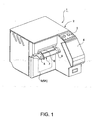
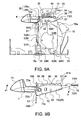
- the printer 1 of this embodiment has an exterior case 2.
- the case 2 has a substantially parallelepiped shaped case main part, and a case extension which has a roughly trapezoidal shape and projects from the right-side portion of the front surface of the case main part.
- An operating panel 3 is formed on the upper surface of this case extension, and the portion following this upper surface portion and declining toward the front forms a cover 4 of a compartment for replaceably accommodating an ink cartridge.
- the cover 5 of this embodiment is rotatable between an upright closed position 5A as shown in Fig. 1, and a full-open position 5B where the cover has fallen down to the substantially horizontal position shown in Fig. 2.
- the cover 5 is fully opened as shown in Fig. 2, the paper receptacle 11 is exposed. In this state, a paper roll 10 can bemounted or replaced.
- An operating lever 7 for opening/closing the cover 5 projects substantially horizontally forward from this discharge port 6.
- the operating lever 7 has a left end portion serving as an operating knob 8, and to the right of the operating knob, a portion serving as a discharge table 9 for guiding horizontally the paper discharged from the discharge port 6.
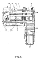
- a paper feed mechanism 32 for transferring the paper 10a delivered from a paper roll 10 in the paper receptacle 11 is incorporated at a position above the paper receptacle 11.
- the ink-jet head 13 is mounted on a carriage 16 reciprocating along a main guide shaft 14 and a sub-guide shaft 15 extending in the width direction of the printer.
- the carriage 16 is connected to a timing belt 17 stretched in the width direction of the printer.
- the timing belt 17 is driven by a carriage motor 18.
- a paper feed motor 23 is arranged immediately below the carriage motor 18, and its motor shaft 23a drives a reducing gear train comprising three gears 24a-24c.
- Gear 24c is fixed to the shaft of a feed roller 25 (see Fig. 3), which is a component part of the feed mechanism 32 described later.
- the feed roller 25 advances the paper 10a delivered from the paper roll 10 to and past the printing position at which the paper 10a is printed by the ink-jet head 13.
- the printed portion of the paper 10a is discharged to the outside through the discharge port 6.
- An auto-cutter 26 is arranged directly above this discharge port 6 to automatically cut the printed part off the paper 10a to discharge a printed sheet of prescribed length.
- the cover 5 constitutes a part of the front surface of the case 2.
- Right and left brackets 5a attached to the lower end on the rear or inner side of the cover 5 are supported rotatably on right and left pins 31, respectively, attached to the main body frame 1A and defining the pivot axis of the cover 5.
- this pivot axis extends in the width direction of the printer.
- the overall configuration and operations of the mechanism for opening and closing the cover 5 are as follows. As described later, the cover 5 is opened and closed together with an operation of right and left parallel link mechanisms (parallelogram linkages) each forming a four-node link mechanism.
- a cover-side feed mechanism section 35 of the feed mechanism 32 is supported on the upper ends of the parallel link mechanisms, and the aforementioned operating lever 7 is attached to this feed mechanism section.
- a locking mechanism is provided for locking the cover 5 and the feed mechanism section 35 in an operating position of the latter corresponding to the closed position of the cover; the locked state is released by operating the operating lever 7.
- the feed mechanism section 35 is moved forward by the parallel link mechanisms while keeping the same posture, and the cover 5 opens along with this.
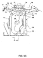
- the feed mechanism 32 has the above mentioned cover-side feed mechanism section 35 which is movable, together with the cover 5, relative to the main body frame 1A, and a frame-side feed mechanism section 34 which is fixed relative to the main body frame 1A.
- Feed mechanism section 34 is located above the transport path of the paper 10a, while feed mechanism section 35 is located below that transport path.
- the feed mechanism section 34 comprises the feed roller 25 (first roller), and a discharge pinch roller 36 (second roller) arranged between the feed roller 25 and the discharge port 6. These rollers are installed on the main body frame 1 A so as to extend horizontally in the printer width direction at substantially the same height.
- the feed roller 25 is arranged upstream of the ink-jet head 13, i.e., toward the rear side of the printer; the pinch roller 36 is arranged toward the front side of the printer, i.e., downstream of the ink-jet head 13 (note that, unless specified otherwise, all references to "upstream” and “downstream” in this text are with respect to the transport direction of the paper).
- the feed mechanism section 35 comprises a feed pinch roller 37 (third roller) resiliently pressed from below against the feed roller 25, and a discharge roller 38 (fourth roller) in contact from below with the pinch roller 36.
- the feed mechanism section 35 further comprises a platen member 39 having an upper surface arranged horizontally between the rollers 37 and 38, and a movable guide 41 arranged behind the roller 37, i.e., on the upstream side thereof.
- the horizontal upper surface of the platen member 39 faces the ink nozzle surface of the ink-jet head 13 with a constant gap in between and defines a printing position 40 of the ink-jet head 13.
- the purpose of the guide 41 is to direct the paper 10a to the nip portion between the feed roller 25 and the pinch roller 37.
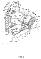
- the discharge roller 38 is connected to a gear train comprising gears 42, 43 and 44 attached rotatably to a frame member of the feed mechanism section 35 (see Fig. 7).
- the gear 44 engages a gear 45 provided at the end of the feed roller 25 (see Fig. 9C) and is thus coupled to the paper feed motor 23.
- the reduction ratio of the gears 42 to 44 is preferably set so that the rotary speed of the discharge roller 38 is slightly higher than that of the feed roller 25. As a result, it is possible to impart a slight tension to the paper 10a passing the printing position 40, and hence to maintain an appropriate gap between the ink-jet head 13 and the printing surface of the paper 10a.
- the pinch roller 36 comprises a plurality of disk-like rollers 36a coaxially carried on a common shaft 36b at uniform intervals; the disk rollers 36a have a sharp or narrow outer peripheral surface.
- the shaft 36b is formed from a coil spring. Therefore, the contact area between the respective peripheral surface of each of the rollers 36a on the one hand and the printing surface of the paper 10a on the other hand is small and there is only a slight contact pressure.
- the rollers 36a come into contact with the printing surface of the paper 10a after printing. However, because the contact area between the recording surface and each roller 36a is small and there is only a slight contact pressure, it is possible to avoid the print quality being reduced by the rollers 36a rubbing the ink immediately after printing, or by staining of the printed surface with ink.
- the first and fourth rollers are driven rollers to which the driving force from the paper feed motor 23 is transferred, while the second and third rollers are pinch rollers.
- either one of the first and third rollers, which come in contact with each other when the feed mechanism section 35 is at its operating position, may be the driven roller, and the other one the pinch roller.
- either one of the second and fourth rollers may be the driven roller and the other one the pinch roller.
- the first and fourth rollers may be pinch rollers and the second and third rollers may be driven rollers.
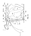
- rollers 37 and 38 of the feed mechanism section 35 are attached to the platen member 39, which in turn is supported on upper ends of the right and left parallel link mechanisms 50L and 50R (only 50R being visible in Fig. 9A).
- Mechanism 50R has a front swinging arm 53R and a rear swinging arm 54R both extending vertically in the closed position of the cover 5.
- Their upper ends 55R and 56R, respectively, are hinge-connected to the right end of a front supporting shaft 51 and rear supporting shaft 52, respectively, that are installed on the platen member 39 to extend in the printer width direction in parallel to each other and horizontally at the same height.
- the lower ends 57R and 58R of these swinging arms 53R and 54R are similarly hinge-connected a front supporting shaft 59R and a rear supporting shaft 60R attached at the same height to the main body frame 1 A.
- the parallel link mechanism 50R comprises, as described above, the platen member 39 of the feed mechanism section 35, the supporting shafts 51, 52, 59R and 60R and the swinging arms 53R and 54R.
- the other parallel link mechanism 50L has the same structure comprising the platen member 39, the supporting shafts 51, 52, 59L and 60L, and a pair of swinging arms 53L and 54L. Due to this linkage, when the platen member 39 is pulled toward the operator, it moves forward and downward while keeping its posture.
- a fixed cutting blade 26b of the auto-cutter 26 is attached to a position of the platen member 39 on the printer front end side, while a movable cutting blade 26a is fixed to the main body frame 1 A side.
- the operating lever 7 comprises a lever body 71 (formed integrally with the operating knob 8 and the discharge table 9), a lever supporting member 72 to which the lever body 71 is attached, and locking hooks 73L (not visible in Fig. 9A) and 73R formed on two rear ends of the lever supporting member 72.
- the lever supporting member 72 comprises a horizontally extending lever body supporting plate portion 72a, a fixed cutting blade cover plate portion 72b, and a coupling plate portion 72c extending from the plate portion 72a rearward while slightly inclining upward. Plate portion 72b is bent downward and rearward from the plate portion 72a and extends from the front to directly below the cutting blade 26b. The rear end portion of the coupling plate portion 72c is bent upward, and the guide 41 is integrally formed therewith.
- Both end portions of the coupling plate portion 72c in the printer width direction form brackets 72d(L) (left) and 72d(R) (right) bent upward at right angles.
- the hooks 73L and 73R are formed at the end of rearward extensions of these brackets 72d(L) and 72d(R).
- the two ends of the supporting shaft 52 rotatably passing through the platen member 39 similarly rotatably pass through middle positions in the forward/backward direction of the brackets 72d(L) and 72d(R).
- the operating lever 7 having the above-mentioned configuration is always pulled diagonally downward, relative to the supporting shaft 52 serving as the rotary center of the operating lever 7, by a pair of coil springs 74R and 74L, whose lower ends are attached to the cover 5, on both end portions on the printer front side.
- These coil springs 74R and 74R urge claws of the hooks 73L and 73R into engagement from below with a pair of left and right hook engaging grooves or cutouts 75L and 75R formed at appropriate positions in the main body frame 1A (see Figs. 6 and 7).
- the claws of the hooks 73L and 73R are released from the grooves 75L and 75R.
- Fig. 10 illustrates a state immediately after such release.
- the locking mechanism is thus composed of the hooks 73L and 73R, the hook engaging groove 75L and 75R, and the coil springs 74L and 74R.
- the upper end portion of the cover 5 is always pressed by the pair of left and right coil springs 74L and 74R against the front swinging arms 53R and 53L.
- the cover 5 therefore rotates forward and backward integrally with the swinging arms 53R and 53L. More specifically, when the feed mechanism section 35 is moved to its operating position, the cover 5 moves to the closed position 5A in linkage therewith. In order to open the cover 5 to the full-open position 5B, on the contrary, it suffices to unlock the mechanism by operating the operating lever 7, and pull the operating lever 7 toward the operator.
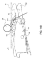
- the guide 41 is integrally formed at the rear end of the lever supporting member 72 of the operating lever 7. By rotating the operating lever 7 around the supporting shaft 52, therefore, the guide 41 also moves up and down around the supporting shaft 52. Operations of the guide 41 will now be described with reference mainly to Figs. 14A to 14C.
- the paper 10a directed by the guide surface 41a to the nip portion between the rollers 25 and 37 is directed from the side of the feed roller 25 diagonally to that nip portion.
- Fig. 14B shows a state in which the operating lever 7 is lifted and locking by the locking mechanism is released to open the cover 5.
- the guide 41 moves downward.
- the highest position of its guide surface 41a when the hooks 73L and 73R have just been released from engagement with the grooves 75R, 75L, is set to be lower than the nip portion between the feed roller 25 and the pinch roller 37.
- the guide 41 is at a position lower than the feed roller 25. Therefore, as shown in Fig. 14C, even when the feed mechanism section 35 moves substantially horizontally toward the front side of the printer as the cover is opened, the guide 41 never comes into contact with the feed roller 25.
- the movable guide 41 shown in Fig. 14C represents a case in the state corresponding to the intermediate one (73B) of the three positions of the hooks 73R (73L) shown in Fig. 10.
- a first control mechanism comprises first engaging portions 77R and 77L formed on the front side of the upper ends of the swinging arms 53R and 53L, respectively, and a second engaging portion, namely the corner portion 72e at the lower end of the plate portion 72b of the operating lever 7. More particularly, as shown in Fig. 10, the engaging portions 77R and 77L draw a locus represented by a one-point chain line B as the swinging arms 53R and 53L pivot around the supporting shaft 59R (59L). Due to the structure explained above, in response to the same movement, corner portion 72e tends to draw a locus C having a radius of curvature smaller than the locus B.
- these loci B and C cross each other, as shown in Fig. 10, at a certain angular position of the cover 5 slightly before the closed position 5A (state shown in Figs. 9A and 9C).
- the engaging portions 77R and 77L abut against the corner portion 72e of the operating lever 7 from below.
- the corner portion 72e is forced to follow the locus B resulting in the front side of the operating lever 7 being pushed up.
- the engaging portions 77R and 77L come off the corner portion 72e.
- the front side of the operating lever 7 therefore moves down under the effect of the spring force of the coil springs 74L and 74R.
- the hooks 73L and 73R of the operating lever 7 move from a position 73A represented by a solid line in Fig. 10 through a position 73B represented by an imaginary line to a locking position 73C represented by another imaginary line.
- the operating lever 7 is forcibly moved to avoid the hooks 73L and 73R hitting and sliding over the surface portions of the main body frame 1A that are in front of the grooves 75L and 75R. According to this embodiment, therefore, only a small operating force is required for locking the cover 5 at the closed position 5A, thus permitting improvement of operability for opening and closing the cover 5.
- the second control mechanism is provided for turning the operating lever's front side upward as the cover is being opened.
- the second control mechanism comprises engagement projections 72f(L) (left) and 72f(R) (right) formed on the left bracket 72d(L) and the right bracket 72d(R), respectively, of the operating lever 7, and contact surfaces 78L and 78R formed on a part of the rear side end face of the upper end portions of the front left and right swinging arms 53L and 53R.
- the positions of these engagement projections and the contact surfaces are set so as to ensure the following operations.
- the engagement projections 72f(L) and 72f(R) of the operating lever 7 come into contact with the contact surfaces 78L and 78R, respectively.
- the engagement projections 72f(L) and 72f(R) are forced to follow the loci of the contact surfaces resulting in the engagement projections being pushed up, such that operating lever 7 is turned around the supporting shaft 52 (in a clockwise direction as viewed in Fig. 10).
- the operating lever 7 With the cover 5 fully opened the operating lever 7 is, therefore, directed diagonally upward, so that there is a sufficiently wide gap under its front end (the end facing the operator).
- the cover 5 Upon closing the cover 5, it is easily possible to insert a finger under the front end of the operating lever 7 and lift the operating lever, hence permitting the closing operation of the cover 5 with a high operability.
- the printer 1 of this embodiment is provided with a microswitch for detecting the guide 41 for the purpose of detecting whether or not the cover 5 is closed and the feed mechanism section 35 is at its operating position.
- a microswitch for detecting whether or not paper 10a is drawn out to the discharge port 6 side, and runs between the frame-side feed mechanism section 34 and the cover-side feed mechanism section 35.
- Microswitches 81 and 82 and actuating levers 83 and 84 serving as detecting elements thereof are attached to the main body frame 1A.
- a downward force is always imparted by a force imparting member (not shown) such as a torsion spring to the levers 83 and 84.
- a force imparting member such as a torsion spring
- the lever 83 is pressed against the guide surface 41a of the guide 41.
- the lever 83 is urged into its lower limit position by the spring force.
- the microswitch 81 is turned on or off in response to the position of the swinging lever 83, thus detecting whether or not the feed mechanism section 35 is at its operating position, i.e., whether or not the cover 5 is at its closed position.
- a slit 41 b is formed in the center portion of the guide 41 in the width direction thereof.
- a force imparting member such as a coil spring that biases the lever into this slit 41 b.
- the state in which the lever 84 is inserted into the slit 41 b represents the lowest limit of the pivotal range of the lever 84.
- levers 83 and 84 serve also as paper retainer for pressing the paper onto the guide surface 41 a to prevent it from floating above the guide surface 41 a.
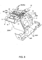
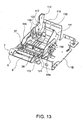
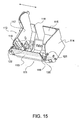
- the paper receptacle 11 has a shape permitting drop-charging of a paper roll 10 from above, and comprises a roll holder 111 and a roll guide 112.
- the roll holder 111 comprises a front wall portion 113, a right side wall portion 114, a rear wall portion 115, and a bottom wall portion 116.
- the roll guide 112 comprises a left side wall portion 117, a rear wall portion 118 and a bottom wall portion 119.
- the roll holder 111 is rotatably supported on a supporting shaft 120 passing horizontally through the bottom wall portion 116 of the roll holder 111 in the printer width direction.
- the supporting shaft 120 is supported by a bottom plate portion 1 B of the main body frame 1A.
- An engagement projection 121 projecting in the transverse direction is formed at a front side position of the right side wall portion 114 of the roll holder 111.
- the roll holder 111 is also tilted forward around the supporting shaft 120 such that its upper opening is directed diagonally forward. It is thus possible to drop a paper roll from diagonally above into the roll holder 111.
- the charging operation of the paper roll is therefore simplified as compared with the case where the paper roll 10 has to dropped from directly above.
- the roll guide 112 is also supported by the supporting shaft 120 which extends through the bottom wall portion of the roll guide 112.
- the roll guide 112 is thus movable along the supporting shaft 120 in the printer width direction, i.e., in the direction of the arrow in Fig. 15. This allows varying the gap between the left side wall portion 117 of the roll guide 112 and the right side wall portion 114 of the roll holder 111. Therefore, the width of the paper receptacle 11 can be adapted to the width of the paper roll 10.
- a detection lever 122 for detecting the remaining amount of paper on the paper roll 10 is attached to the roll guide 112.
- all constituent parts of the roll holder 111 namely the front wall portion 113, the right side wall portion 114, the rear wall portion 115 and the bottom wall portion 116, constitute a holder moving section which rotates forward as the cover 5 is opened.
- the holder moving section need not necessarily include all these constituent parts but should include at least the front wall portion 113.
- the operator uses his fingers or the like to push up the operating lever 7 against the spring force of the coil springs 74L and 74R.
- the operating lever 7 rotates around the supporting shaft 52, and the hooks 73L and 73R go down to come off the grooves 75L and 75R, thereby locking is released (see Fig. 10).
- the mechanism for unlocking is simplified, and this is advantageous for downsizing the printer.
- the guide 41 Upon unlocking, the guide 41 also moves down, together with the hooks 73L and 73R, to avoid coming into contact with the feed roller 25 of the frame-side feed mechanism section 34.
- the platen member 39 After unlocking, the platen member 39 is displaced forward while keeping its horizontal posture under the action of the parallel link mechanisms 50L and 50R by pulling the leading end portion of the operating lever 7.
- the cover 5 By pulling the operating lever 7 toward the printer front, as described above, the cover 5 can be opened.
- the cover 5 falls down forward, the front end surface 54a of the swinging arm 54R of the right parallel link mechanism 50R comes into contact from the rear side with the engagement projection 121 of the roll holder 111. Subsequently, the roll holder 111 also falls down forward around the supporting shaft 120.
- the rollers 37 and 38, and the fixed cutting blade 26b are attached to the platen member 39, and the feed mechanism section 35 comprising these components is separated from the feed mechanism section 34 attached to the main body frame 1 A.
- the paper drawn off the paper roll 10 on the feed mechanism section 35 and then closing the cover 5, the paper is automatically arranged in a printable state. It is thus possible to very easily accomplish the setting of the paper after a new paper roll has been inserted.
- the roll holder 111 also falls down forward when the cover 5 is opened, it is, furthermore, possible to easily insert the paper roll 10 into the paper receptacle 11 as compared with the conventional case where the paper roll 10 has to be dropped into the roll holder 111 from above beyond the front wall portion 113 of the paper receptacle.
- the effective opening area of the paper receptacle for loading or replacing a paper roll is enlarged. It is therefore easily possible to load a paper roll with a high operability.
- the effective opening of the paper receptacle 11 can be enlarged in the open state of the cover 5 without the need to enlarge the opening of the paper receptacle. It is therefore possible to reduce the opening of the paper receptacle without the risk of impairing operability of the charging operation of the paper roll. This is very advantageous for achieving a small-sized and compact printer.
- the plate portion 72b of the operating lever 7 moves upward.
- the cutting edge of the fixed cutting blade 26b is covered with the plate portion 72b.
- the cover-side feed mechanism section supported by the parallel link mechanisms moves along with this from the position above the paper receptacle toward the front of the printer. It is therefore possible to provide a wide space for charging a paper roll into the paper receptacle in the opened state of the cover.
- the cover-side feed mechanism section moves closer to the frame-side feed mechanism section while keeping its posture. It is thus possible to automatically achieve the printable state with the paper held between the two sections. Since the cover-side feed mechanism section is supported by the parallel link mechanisms, it is possible to always position with a high accuracy this feed mechanism section at an appropriate position relative to the printing head fixed to the main body frame.
Landscapes
- Accessory Devices And Overall Control Thereof (AREA)
- Replacement Of Web Rolls (AREA)
- Handling Of Sheets (AREA)
- Particle Formation And Scattering Control In Inkjet Printers (AREA)
- Massaging Devices (AREA)
Applications Claiming Priority (14)
| Application Number | Priority Date | Filing Date | Title |
|---|---|---|---|
| JP26939499 | 1999-09-22 | ||
| JP26939499 | 1999-09-22 | ||
| JP2000022908 | 2000-01-31 | ||
| JP2000022908A JP4221866B2 (ja) | 2000-01-31 | 2000-01-31 | ロール紙装填機構およびロール紙プリンタ |
| JP2000024424 | 2000-02-01 | ||
| JP2000024424A JP2001213551A (ja) | 2000-02-01 | 2000-02-01 | ロール紙装填機構およびロール紙プリンタ |
| JP2000104971A JP3855591B2 (ja) | 2000-04-06 | 2000-04-06 | ロール紙装填機構およびロール紙プリンタ |
| JP2000104971 | 2000-04-06 | ||
| JP2000111216A JP3947897B2 (ja) | 2000-04-12 | 2000-04-12 | プリンタ |
| JP2000111216 | 2000-04-12 | ||
| JP2000169242A JP3855605B2 (ja) | 2000-06-06 | 2000-06-06 | ロール紙装填機構およびロール紙プリンタ |
| JP2000169241A JP3855604B2 (ja) | 2000-06-06 | 2000-06-06 | ロール紙装填機構およびロール紙プリンタ |
| JP2000169241 | 2000-06-06 | ||
| JP2000169242 | 2000-06-06 |
Publications (3)
| Publication Number | Publication Date |
|---|---|
| EP1086821A2 EP1086821A2 (en) | 2001-03-28 |
| EP1086821A3 EP1086821A3 (en) | 2001-05-16 |
| EP1086821B1 true EP1086821B1 (en) | 2006-07-26 |
Family
ID=27566775
Family Applications (1)
| Application Number | Title | Priority Date | Filing Date |
|---|---|---|---|
| EP00120149A Expired - Lifetime EP1086821B1 (en) | 1999-09-22 | 2000-09-21 | Printer |
Country Status (7)
| Country | Link |
|---|---|
| US (1) | US6474883B1 (zh) |
| EP (1) | EP1086821B1 (zh) |
| KR (1) | KR100566221B1 (zh) |
| CN (1) | CN1170690C (zh) |
| AT (1) | ATE334003T1 (zh) |
| DE (1) | DE60029526T2 (zh) |
| ES (1) | ES2267440T3 (zh) |
Cited By (2)
| Publication number | Priority date | Publication date | Assignee | Title |
|---|---|---|---|---|
| DE102006056590A1 (de) * | 2006-11-29 | 2008-06-05 | Kurt Vignold Gmbh & Co. Handels Kg | Verfahren zum Erstellen von Proofs und Druckersystem zur Durchführung des vorgenannten Verfahrens |
| CN109147158A (zh) * | 2018-11-07 | 2019-01-04 | 苏州日宝科技有限责任公司 | 一种纸币存款机 |
Families Citing this family (42)
| Publication number | Priority date | Publication date | Assignee | Title |
|---|---|---|---|---|
| AUPP702498A0 (en) * | 1998-11-09 | 1998-12-03 | Silverbrook Research Pty Ltd | Image creation method and apparatus (ART77) |
| FR2796001B1 (fr) * | 1999-07-09 | 2001-10-05 | A P S Engineering | Dispositif de deverrouillage d'un compartiment d'un mecanisme ouvrant |
| FR2830003B1 (fr) * | 2001-09-21 | 2003-12-05 | Axiohm | Appareil distributeur de troncons d'un ruban |
| JP3864941B2 (ja) * | 2003-08-22 | 2007-01-10 | 船井電機株式会社 | プリンタ |
| JP4107261B2 (ja) * | 2003-11-14 | 2008-06-25 | セイコーエプソン株式会社 | カッタ機構を備えたプリンタ |
| JP4517743B2 (ja) * | 2004-06-23 | 2010-08-04 | セイコーエプソン株式会社 | 印刷ユニット |
| US7517165B2 (en) * | 2004-06-23 | 2009-04-14 | Seiko Epson Corporation | Printing unit with frame locking mechanism and release lever |
| US20050286960A1 (en) * | 2004-06-29 | 2005-12-29 | Le-Jen Wang | Self-positioning guard of a printer for controlling access to an opening on a housing of the printer |
| JP4587474B2 (ja) * | 2005-06-30 | 2010-11-24 | シチズンホールディングス株式会社 | プリンタ |
| JP2007083478A (ja) * | 2005-09-21 | 2007-04-05 | Seiko Epson Corp | ロール紙プリンタ |
| US7971989B2 (en) * | 2005-12-07 | 2011-07-05 | Seiko Epson Corporation | Printer used with rolled sheet |
| US7878724B2 (en) * | 2005-12-27 | 2011-02-01 | Seiko Epson Corporation | Printer |
| BRPI0600440B1 (pt) * | 2006-03-06 | 2018-10-09 | Bematech Ind E Comercio De Equipamentos Eletronicos S/A | impressora com cartucho modular |
| BRPI0600439B1 (pt) * | 2006-03-06 | 2019-01-22 | Bematech S A | impressora térmica e respectivo método de acionamento |
| JP2008049641A (ja) * | 2006-08-28 | 2008-03-06 | Canon Inc | 印刷装置および印刷装置の制御方法 |
| CN100493922C (zh) * | 2007-02-07 | 2009-06-03 | 上海博施电子技术有限公司 | 一种打印机用推抬式开仓机构 |
| JP5082749B2 (ja) | 2007-10-15 | 2012-11-28 | セイコーエプソン株式会社 | プリンタ |
| JP5109616B2 (ja) * | 2007-11-20 | 2012-12-26 | セイコーエプソン株式会社 | プリンタ |
| US8128298B2 (en) * | 2007-12-05 | 2012-03-06 | International Business Machines Corporation | Hinge with sliding pivot transfer |
| JP5200567B2 (ja) * | 2008-02-07 | 2013-06-05 | セイコーエプソン株式会社 | プリンタの開閉蓋構造およびプリンタ |
| JP5298954B2 (ja) * | 2008-04-10 | 2013-09-25 | セイコーエプソン株式会社 | プリンターの記録紙搬送制御方法およびプリンター |
| JP5316087B2 (ja) * | 2009-03-02 | 2013-10-16 | セイコーエプソン株式会社 | オートカッターおよびオートカッター付きプリンター |
| CA2666239A1 (en) * | 2009-05-20 | 2010-11-20 | The Imaging Systems Group Inc. | Hybrid printer-feeder mechanism |
| JP5445028B2 (ja) * | 2009-10-23 | 2014-03-19 | セイコーエプソン株式会社 | プラテン支持機構およびロール紙プリンター |
| JP5471583B2 (ja) | 2010-02-24 | 2014-04-16 | セイコーエプソン株式会社 | ロール媒体給送装置及び記録装置 |
| JP5621294B2 (ja) * | 2010-03-29 | 2014-11-12 | セイコーエプソン株式会社 | ロール紙プリンター及びロール紙プリンターのカバー開閉方法 |
| JP5471779B2 (ja) * | 2010-04-28 | 2014-04-16 | セイコーエプソン株式会社 | ロール紙装填機構および印刷装置 |
| JP2012006728A (ja) | 2010-06-25 | 2012-01-12 | Seiko Epson Corp | 消費材収容装置、液体噴射装置、および消費材収容装置の制御方法 |
| JP2012068492A (ja) * | 2010-09-24 | 2012-04-05 | Fuji Xerox Co Ltd | 搬送装置および画像形成装置 |
| US9944484B2 (en) * | 2012-12-17 | 2018-04-17 | Seiko Epson Corporation | Transport device and recording apparatus |
| KR101525501B1 (ko) * | 2013-05-15 | 2015-06-03 | 코스테크 주식회사 | 소재 공급 장치 |
| JP6398174B2 (ja) * | 2013-10-22 | 2018-10-03 | セイコーエプソン株式会社 | 記録装置 |
| JP6248599B2 (ja) * | 2013-12-13 | 2017-12-20 | セイコーエプソン株式会社 | 印刷装置 |
| WO2015093008A1 (ja) | 2013-12-18 | 2015-06-25 | セイコーエプソン株式会社 | 液体供給ユニット |
| US20150183248A1 (en) * | 2013-12-27 | 2015-07-02 | Seiko Epson Corporation | Recording apparatus |
| JP6250438B2 (ja) * | 2014-02-28 | 2017-12-20 | 富士通コンポーネント株式会社 | プリンタ装置 |
| JP6435848B2 (ja) * | 2014-12-22 | 2018-12-12 | セイコーエプソン株式会社 | 印刷装置 |
| JP2016124226A (ja) | 2015-01-06 | 2016-07-11 | セイコーエプソン株式会社 | 印刷装置 |
| JP2018001719A (ja) * | 2016-07-08 | 2018-01-11 | 東芝テック株式会社 | プリンタ |
| JP6891610B2 (ja) * | 2017-04-13 | 2021-06-18 | ブラザー工業株式会社 | 印刷装置 |
| WO2021124587A1 (ja) * | 2019-12-20 | 2021-06-24 | 富士通フロンテック株式会社 | ロール支持装置 |
| JP1709435S (zh) * | 2021-08-31 | 2022-03-10 |
Family Cites Families (17)
| Publication number | Priority date | Publication date | Assignee | Title |
|---|---|---|---|---|
| DE3334217A1 (de) * | 1983-09-22 | 1985-04-04 | Goerz Electro Gmbh, Wien | Transportvorrichtung fuer den registrierstreifen eines elektrischen registriergeraetes |
| JPS60192668A (ja) * | 1984-03-14 | 1985-10-01 | Toshiba Corp | 画像形成装置 |
| JPH0643224B2 (ja) | 1984-06-20 | 1994-06-08 | 株式会社東芝 | 記録装置 |
| DE3583378D1 (de) * | 1984-10-02 | 1991-08-08 | Fujitsu Ltd | Drucker mit einer von der vorderseite einfuehrbare papiervorschubeinrichtung. |
| JPS6184270A (ja) | 1984-10-02 | 1986-04-28 | Fujitsu Ltd | 印字部を引き出し可能なプリンタ |
| JPS62158067A (ja) | 1986-01-07 | 1987-07-14 | Canon Inc | 記録装置 |
| JPH0679855B2 (ja) | 1986-10-15 | 1994-10-12 | 株式会社セコニツク | 記録装置 |
| JP2537904B2 (ja) | 1987-10-09 | 1996-09-25 | 松下電器産業株式会社 | 感熱記録装置 |
| JPH01249371A (ja) | 1988-03-31 | 1989-10-04 | Perifueraru Intaafueisu Ltd Kk | 熱記録装置における記録部支持機構 |
| KR0133931B1 (ko) * | 1988-11-30 | 1998-04-20 | 오가 노리오 | 프린터 |
| JPH03258575A (ja) | 1990-03-08 | 1991-11-18 | Mitsubishi Electric Corp | プリンタ装置 |
| JPH05147291A (ja) | 1991-11-28 | 1993-06-15 | Sony Corp | プリンタ |
| US5528278A (en) | 1991-11-28 | 1996-06-18 | Sony Corporation | Video printer having rewind function to improve transfer sheet utilization |
| JPH082754A (ja) | 1994-06-22 | 1996-01-09 | Matsushita Graphic Commun Syst Inc | インクジェット記録装置 |
| US6022158A (en) | 1997-04-02 | 2000-02-08 | Seiko Epson Corporation | Roll paper loading mechanism for printer |
| JP3617243B2 (ja) | 1997-04-02 | 2005-02-02 | セイコーエプソン株式会社 | プリンタのロール紙装填機構 |
| US5887999A (en) | 1997-10-06 | 1999-03-30 | Axiohm Ipb Inc. | Paper loading mechanism |
-
2000
- 2000-09-19 US US09/664,951 patent/US6474883B1/en not_active Expired - Lifetime
- 2000-09-19 KR KR1020000054903A patent/KR100566221B1/ko not_active IP Right Cessation
- 2000-09-21 EP EP00120149A patent/EP1086821B1/en not_active Expired - Lifetime
- 2000-09-21 AT AT00120149T patent/ATE334003T1/de not_active IP Right Cessation
- 2000-09-21 CN CNB001318586A patent/CN1170690C/zh not_active Expired - Fee Related
- 2000-09-21 ES ES00120149T patent/ES2267440T3/es not_active Expired - Lifetime
- 2000-09-21 DE DE60029526T patent/DE60029526T2/de not_active Expired - Lifetime
Cited By (3)
| Publication number | Priority date | Publication date | Assignee | Title |
|---|---|---|---|---|
| DE102006056590A1 (de) * | 2006-11-29 | 2008-06-05 | Kurt Vignold Gmbh & Co. Handels Kg | Verfahren zum Erstellen von Proofs und Druckersystem zur Durchführung des vorgenannten Verfahrens |
| CN109147158A (zh) * | 2018-11-07 | 2019-01-04 | 苏州日宝科技有限责任公司 | 一种纸币存款机 |
| CN109147158B (zh) * | 2018-11-07 | 2024-02-06 | 苏州日宝科技有限责任公司 | 一种纸币存款机 |
Also Published As
| Publication number | Publication date |
|---|---|
| KR100566221B1 (ko) | 2006-03-29 |
| DE60029526D1 (de) | 2006-09-07 |
| EP1086821A2 (en) | 2001-03-28 |
| KR20010050520A (ko) | 2001-06-15 |
| DE60029526T2 (de) | 2007-07-19 |
| ATE334003T1 (de) | 2006-08-15 |
| EP1086821A3 (en) | 2001-05-16 |
| CN1294980A (zh) | 2001-05-16 |
| ES2267440T3 (es) | 2007-03-16 |
| US6474883B1 (en) | 2002-11-05 |
| CN1170690C (zh) | 2004-10-13 |
Similar Documents
| Publication | Publication Date | Title |
|---|---|---|
| EP1086821B1 (en) | Printer | |
| KR101505205B1 (ko) | 커터가 달린 프린터 | |
| EP1095782B1 (en) | Printer | |
| US7410315B2 (en) | Paper discharge mechanism for a printer, and a printer | |
| US7764490B2 (en) | Display devices and image recording apparatus comprising the same | |
| US7455285B2 (en) | Media handling accessory and method | |
| JP3832219B2 (ja) | ロール紙収容部を備えたプリンタ | |
| US5026184A (en) | Office machine | |
| WO1982001515A1 (en) | Selective paper insertion and feeding means for individual sheet printing apparatus | |
| WO1982001513A1 (en) | Print wheel mounting arrangement for print head and ribbon cartridge assembly | |
| US7708262B2 (en) | Media handling system | |
| US9592975B2 (en) | Paper transfer device | |
| JP2822416B2 (ja) | プリンタの筐体構造 | |
| US8523465B2 (en) | Printer with multi-curved intermediate transportation path | |
| WO1998021041A1 (fr) | Appareil d'enregistrement | |
| JP2001205896A (ja) | ロール紙装填機構およびロール紙プリンタ | |
| US5708927A (en) | Driving mechanism for a fixing apparatus having an idle gear disengageable from a fixing roller gear by gravity | |
| JPH0616766Y2 (ja) | プリンタトップカバー | |
| US4995746A (en) | Office machine | |
| US8550734B2 (en) | Transportation guide mechanism and recording device having the same | |
| JP2000108439A (ja) | ロール紙用プリンタ | |
| JP3565043B2 (ja) | プリンタのロール紙装填機構 | |
| JP3710233B2 (ja) | プリンタ | |
| JP3654008B2 (ja) | ロール紙用プリンタ | |
| JP3750124B2 (ja) | 給紙装置及び印字装置 |
Legal Events
| Date | Code | Title | Description |
|---|---|---|---|
| PUAI | Public reference made under article 153(3) epc to a published international application that has entered the european phase |
Free format text: ORIGINAL CODE: 0009012 |
|
| AK | Designated contracting states |
Kind code of ref document: A2 Designated state(s): AT BE CH CY DE DK ES FI FR GB GR IE IT LI LU MC NL PT SE |
|
| AX | Request for extension of the european patent |
Free format text: AL;LT;LV;MK;RO;SI |
|
| PUAL | Search report despatched |
Free format text: ORIGINAL CODE: 0009013 |
|
| AK | Designated contracting states |
Kind code of ref document: A3 Designated state(s): AT BE CH CY DE DK ES FI FR GB GR IE IT LI LU MC NL PT SE |
|
| AX | Request for extension of the european patent |
Free format text: AL;LT;LV;MK;RO;SI |
|
| 17P | Request for examination filed |
Effective date: 20010704 |
|
| AKX | Designation fees paid |
Free format text: AT BE CH CY DE DK ES FI FR GB GR IE IT LI LU MC NL PT SE |
|
| 17Q | First examination report despatched |
Effective date: 20050315 |
|
| GRAP | Despatch of communication of intention to grant a patent |
Free format text: ORIGINAL CODE: EPIDOSNIGR1 |
|
| GRAS | Grant fee paid |
Free format text: ORIGINAL CODE: EPIDOSNIGR3 |
|
| GRAA | (expected) grant |
Free format text: ORIGINAL CODE: 0009210 |
|
| AK | Designated contracting states |
Kind code of ref document: B1 Designated state(s): AT BE CH CY DE DK ES FI FR GB GR IE IT LI LU MC NL PT SE |
|
| PG25 | Lapsed in a contracting state [announced via postgrant information from national office to epo] |
Ref country code: AT Free format text: LAPSE BECAUSE OF FAILURE TO SUBMIT A TRANSLATION OF THE DESCRIPTION OR TO PAY THE FEE WITHIN THE PRESCRIBED TIME-LIMIT Effective date: 20060726 Ref country code: FI Free format text: LAPSE BECAUSE OF FAILURE TO SUBMIT A TRANSLATION OF THE DESCRIPTION OR TO PAY THE FEE WITHIN THE PRESCRIBED TIME-LIMIT Effective date: 20060726 |
|
| REG | Reference to a national code |
Ref country code: GB Ref legal event code: FG4D |
|
| REG | Reference to a national code |
Ref country code: CH Ref legal event code: EP |
|
| REG | Reference to a national code |
Ref country code: IE Ref legal event code: FG4D |
|
| REG | Reference to a national code |
Ref country code: CH Ref legal event code: NV Representative=s name: E. BLUM & CO. PATENTANWAELTE |
|
| REF | Corresponds to: |
Ref document number: 60029526 Country of ref document: DE Date of ref document: 20060907 Kind code of ref document: P |
|
| PG25 | Lapsed in a contracting state [announced via postgrant information from national office to epo] |
Ref country code: IE Free format text: LAPSE BECAUSE OF NON-PAYMENT OF DUE FEES Effective date: 20060921 |
|
| PG25 | Lapsed in a contracting state [announced via postgrant information from national office to epo] |
Ref country code: MC Free format text: LAPSE BECAUSE OF NON-PAYMENT OF DUE FEES Effective date: 20060930 |
|
| PG25 | Lapsed in a contracting state [announced via postgrant information from national office to epo] |
Ref country code: DK Free format text: LAPSE BECAUSE OF FAILURE TO SUBMIT A TRANSLATION OF THE DESCRIPTION OR TO PAY THE FEE WITHIN THE PRESCRIBED TIME-LIMIT Effective date: 20061026 Ref country code: SE Free format text: LAPSE BECAUSE OF FAILURE TO SUBMIT A TRANSLATION OF THE DESCRIPTION OR TO PAY THE FEE WITHIN THE PRESCRIBED TIME-LIMIT Effective date: 20061026 |
|
| PG25 | Lapsed in a contracting state [announced via postgrant information from national office to epo] |
Ref country code: PT Free format text: LAPSE BECAUSE OF FAILURE TO SUBMIT A TRANSLATION OF THE DESCRIPTION OR TO PAY THE FEE WITHIN THE PRESCRIBED TIME-LIMIT Effective date: 20061226 |
|
| ET | Fr: translation filed | ||
| REG | Reference to a national code |
Ref country code: ES Ref legal event code: FG2A Ref document number: 2267440 Country of ref document: ES Kind code of ref document: T3 |
|
| PLBE | No opposition filed within time limit |
Free format text: ORIGINAL CODE: 0009261 |
|
| STAA | Information on the status of an ep patent application or granted ep patent |
Free format text: STATUS: NO OPPOSITION FILED WITHIN TIME LIMIT |
|
| 26N | No opposition filed |
Effective date: 20070427 |
|
| REG | Reference to a national code |
Ref country code: CH Ref legal event code: PFA Owner name: SEIKO EPSON CORPORATION Free format text: SEIKO EPSON CORPORATION#4-1, NISHI-SHINJUKU 2-CHOME#SHINJUKU-KU, TOKYO 163-0811 (JP) -TRANSFER TO- SEIKO EPSON CORPORATION#4-1, NISHI-SHINJUKU 2-CHOME#SHINJUKU-KU, TOKYO 163-0811 (JP) |
|
| PG25 | Lapsed in a contracting state [announced via postgrant information from national office to epo] |
Ref country code: GR Free format text: LAPSE BECAUSE OF FAILURE TO SUBMIT A TRANSLATION OF THE DESCRIPTION OR TO PAY THE FEE WITHIN THE PRESCRIBED TIME-LIMIT Effective date: 20061027 |
|
| PG25 | Lapsed in a contracting state [announced via postgrant information from national office to epo] |
Ref country code: LU Free format text: LAPSE BECAUSE OF NON-PAYMENT OF DUE FEES Effective date: 20060921 |
|
| PG25 | Lapsed in a contracting state [announced via postgrant information from national office to epo] |
Ref country code: CY Free format text: LAPSE BECAUSE OF FAILURE TO SUBMIT A TRANSLATION OF THE DESCRIPTION OR TO PAY THE FEE WITHIN THE PRESCRIBED TIME-LIMIT Effective date: 20060726 |
|
| REG | Reference to a national code |
Ref country code: FR Ref legal event code: PLFP Year of fee payment: 17 |
|
| PGFP | Annual fee paid to national office [announced via postgrant information from national office to epo] |
Ref country code: NL Payment date: 20160810 Year of fee payment: 17 |
|
| PGFP | Annual fee paid to national office [announced via postgrant information from national office to epo] |
Ref country code: GB Payment date: 20160921 Year of fee payment: 17 Ref country code: IT Payment date: 20160921 Year of fee payment: 17 Ref country code: CH Payment date: 20160914 Year of fee payment: 17 Ref country code: DE Payment date: 20160913 Year of fee payment: 17 |
|
| PGFP | Annual fee paid to national office [announced via postgrant information from national office to epo] |
Ref country code: FR Payment date: 20160816 Year of fee payment: 17 |
|
| PGFP | Annual fee paid to national office [announced via postgrant information from national office to epo] |
Ref country code: BE Payment date: 20160815 Year of fee payment: 17 Ref country code: ES Payment date: 20160810 Year of fee payment: 17 |
|
| REG | Reference to a national code |
Ref country code: DE Ref legal event code: R119 Ref document number: 60029526 Country of ref document: DE |
|
| REG | Reference to a national code |
Ref country code: CH Ref legal event code: PL |
|
| REG | Reference to a national code |
Ref country code: NL Ref legal event code: MM Effective date: 20171001 |
|
| GBPC | Gb: european patent ceased through non-payment of renewal fee |
Effective date: 20170921 |
|
| REG | Reference to a national code |
Ref country code: BE Ref legal event code: MM Effective date: 20170930 |
|
| PG25 | Lapsed in a contracting state [announced via postgrant information from national office to epo] |
Ref country code: NL Free format text: LAPSE BECAUSE OF NON-PAYMENT OF DUE FEES Effective date: 20171001 |
|
| REG | Reference to a national code |
Ref country code: FR Ref legal event code: ST Effective date: 20180531 |
|
| PG25 | Lapsed in a contracting state [announced via postgrant information from national office to epo] |
Ref country code: LI Free format text: LAPSE BECAUSE OF NON-PAYMENT OF DUE FEES Effective date: 20170930 Ref country code: GB Free format text: LAPSE BECAUSE OF NON-PAYMENT OF DUE FEES Effective date: 20170921 Ref country code: DE Free format text: LAPSE BECAUSE OF NON-PAYMENT OF DUE FEES Effective date: 20180404 Ref country code: CH Free format text: LAPSE BECAUSE OF NON-PAYMENT OF DUE FEES Effective date: 20170930 |
|
| PG25 | Lapsed in a contracting state [announced via postgrant information from national office to epo] |
Ref country code: FR Free format text: LAPSE BECAUSE OF NON-PAYMENT OF DUE FEES Effective date: 20171002 Ref country code: IT Free format text: LAPSE BECAUSE OF NON-PAYMENT OF DUE FEES Effective date: 20170921 Ref country code: BE Free format text: LAPSE BECAUSE OF NON-PAYMENT OF DUE FEES Effective date: 20170930 |
|
| REG | Reference to a national code |
Ref country code: ES Ref legal event code: FD2A Effective date: 20181018 |
|
| PG25 | Lapsed in a contracting state [announced via postgrant information from national office to epo] |
Ref country code: ES Free format text: LAPSE BECAUSE OF NON-PAYMENT OF DUE FEES Effective date: 20170922 |