EP1069295A2 - Brennkraftmaschine und Generatorkombination - Google Patents
Brennkraftmaschine und Generatorkombination Download PDFInfo
- Publication number
- EP1069295A2 EP1069295A2 EP00305912A EP00305912A EP1069295A2 EP 1069295 A2 EP1069295 A2 EP 1069295A2 EP 00305912 A EP00305912 A EP 00305912A EP 00305912 A EP00305912 A EP 00305912A EP 1069295 A2 EP1069295 A2 EP 1069295A2
- Authority
- EP
- European Patent Office
- Prior art keywords
- engine
- case
- fuel
- undercover
- reinforcing frames
- Prior art date
- Legal status (The legal status is an assumption and is not a legal conclusion. Google has not performed a legal analysis and makes no representation as to the accuracy of the status listed.)
- Granted
Links
- 239000000446 fuel Substances 0.000 claims abstract description 50
- 230000003014 reinforcing effect Effects 0.000 claims abstract description 39
- 239000002828 fuel tank Substances 0.000 claims abstract description 35
- 238000013016 damping Methods 0.000 claims description 17
- 238000012423 maintenance Methods 0.000 abstract description 10
- 230000010354 integration Effects 0.000 abstract description 4
- 238000001816 cooling Methods 0.000 description 24
- 239000007858 starting material Substances 0.000 description 7
- 239000000463 material Substances 0.000 description 4
- XAGFODPZIPBFFR-UHFFFAOYSA-N aluminium Chemical compound [Al] XAGFODPZIPBFFR-UHFFFAOYSA-N 0.000 description 3
- 229910052782 aluminium Inorganic materials 0.000 description 3
- 238000004512 die casting Methods 0.000 description 3
- 238000000034 method Methods 0.000 description 3
- 229920003002 synthetic resin Polymers 0.000 description 3
- 239000000057 synthetic resin Substances 0.000 description 3
- 238000005452 bending Methods 0.000 description 2
- 238000007599 discharging Methods 0.000 description 2
- 230000000694 effects Effects 0.000 description 2
- 230000002093 peripheral effect Effects 0.000 description 2
- 230000033228 biological regulation Effects 0.000 description 1
- 230000000903 blocking effect Effects 0.000 description 1
- 230000003247 decreasing effect Effects 0.000 description 1
- 230000005764 inhibitory process Effects 0.000 description 1
- 230000010349 pulsation Effects 0.000 description 1
- 230000035939 shock Effects 0.000 description 1
Images


Classifications
-
- F—MECHANICAL ENGINEERING; LIGHTING; HEATING; WEAPONS; BLASTING
- F16—ENGINEERING ELEMENTS AND UNITS; GENERAL MEASURES FOR PRODUCING AND MAINTAINING EFFECTIVE FUNCTIONING OF MACHINES OR INSTALLATIONS; THERMAL INSULATION IN GENERAL
- F16M—FRAMES, CASINGS OR BEDS OF ENGINES, MACHINES OR APPARATUS, NOT SPECIFIC TO ENGINES, MACHINES OR APPARATUS PROVIDED FOR ELSEWHERE; STANDS; SUPPORTS
- F16M3/00—Portable or wheeled frames or beds, e.g. for emergency power-supply aggregates, compressor sets
-
- F—MECHANICAL ENGINEERING; LIGHTING; HEATING; WEAPONS; BLASTING
- F02—COMBUSTION ENGINES; HOT-GAS OR COMBUSTION-PRODUCT ENGINE PLANTS
- F02B—INTERNAL-COMBUSTION PISTON ENGINES; COMBUSTION ENGINES IN GENERAL
- F02B75/00—Other engines
- F02B75/16—Engines characterised by number of cylinders, e.g. single-cylinder engines
-
- F—MECHANICAL ENGINEERING; LIGHTING; HEATING; WEAPONS; BLASTING
- F02—COMBUSTION ENGINES; HOT-GAS OR COMBUSTION-PRODUCT ENGINE PLANTS
- F02B—INTERNAL-COMBUSTION PISTON ENGINES; COMBUSTION ENGINES IN GENERAL
- F02B63/00—Adaptations of engines for driving pumps, hand-held tools or electric generators; Portable combinations of engines with engine-driven devices
- F02B63/04—Adaptations of engines for driving pumps, hand-held tools or electric generators; Portable combinations of engines with engine-driven devices for electric generators
-
- F—MECHANICAL ENGINEERING; LIGHTING; HEATING; WEAPONS; BLASTING
- F02—COMBUSTION ENGINES; HOT-GAS OR COMBUSTION-PRODUCT ENGINE PLANTS
- F02B—INTERNAL-COMBUSTION PISTON ENGINES; COMBUSTION ENGINES IN GENERAL
- F02B77/00—Component parts, details or accessories, not otherwise provided for
- F02B77/11—Thermal or acoustic insulation
- F02B77/13—Acoustic insulation
-
- F—MECHANICAL ENGINEERING; LIGHTING; HEATING; WEAPONS; BLASTING
- F16—ENGINEERING ELEMENTS AND UNITS; GENERAL MEASURES FOR PRODUCING AND MAINTAINING EFFECTIVE FUNCTIONING OF MACHINES OR INSTALLATIONS; THERMAL INSULATION IN GENERAL
- F16F—SPRINGS; SHOCK-ABSORBERS; MEANS FOR DAMPING VIBRATION
- F16F15/00—Suppression of vibrations in systems; Means or arrangements for avoiding or reducing out-of-balance forces, e.g. due to motion
- F16F15/02—Suppression of vibrations of non-rotating, e.g. reciprocating systems; Suppression of vibrations of rotating systems by use of members not moving with the rotating systems
- F16F15/04—Suppression of vibrations of non-rotating, e.g. reciprocating systems; Suppression of vibrations of rotating systems by use of members not moving with the rotating systems using elastic means
- F16F15/08—Suppression of vibrations of non-rotating, e.g. reciprocating systems; Suppression of vibrations of rotating systems by use of members not moving with the rotating systems using elastic means with rubber springs ; with springs made of rubber and metal
-
- F—MECHANICAL ENGINEERING; LIGHTING; HEATING; WEAPONS; BLASTING
- F02—COMBUSTION ENGINES; HOT-GAS OR COMBUSTION-PRODUCT ENGINE PLANTS
- F02B—INTERNAL-COMBUSTION PISTON ENGINES; COMBUSTION ENGINES IN GENERAL
- F02B63/00—Adaptations of engines for driving pumps, hand-held tools or electric generators; Portable combinations of engines with engine-driven devices
- F02B63/04—Adaptations of engines for driving pumps, hand-held tools or electric generators; Portable combinations of engines with engine-driven devices for electric generators
- F02B63/044—Adaptations of engines for driving pumps, hand-held tools or electric generators; Portable combinations of engines with engine-driven devices for electric generators the engine-generator unit being placed on a frame or in an housing
- F02B2063/045—Frames for generator-engine sets
-
- F—MECHANICAL ENGINEERING; LIGHTING; HEATING; WEAPONS; BLASTING
- F02—COMBUSTION ENGINES; HOT-GAS OR COMBUSTION-PRODUCT ENGINE PLANTS
- F02B—INTERNAL-COMBUSTION PISTON ENGINES; COMBUSTION ENGINES IN GENERAL
- F02B63/00—Adaptations of engines for driving pumps, hand-held tools or electric generators; Portable combinations of engines with engine-driven devices
- F02B63/04—Adaptations of engines for driving pumps, hand-held tools or electric generators; Portable combinations of engines with engine-driven devices for electric generators
- F02B63/044—Adaptations of engines for driving pumps, hand-held tools or electric generators; Portable combinations of engines with engine-driven devices for electric generators the engine-generator unit being placed on a frame or in an housing
- F02B2063/046—Handles adapted therefor, e.g. handles or grips for movable units
-
- F—MECHANICAL ENGINEERING; LIGHTING; HEATING; WEAPONS; BLASTING
- F02—COMBUSTION ENGINES; HOT-GAS OR COMBUSTION-PRODUCT ENGINE PLANTS
- F02B—INTERNAL-COMBUSTION PISTON ENGINES; COMBUSTION ENGINES IN GENERAL
- F02B63/00—Adaptations of engines for driving pumps, hand-held tools or electric generators; Portable combinations of engines with engine-driven devices
- F02B63/04—Adaptations of engines for driving pumps, hand-held tools or electric generators; Portable combinations of engines with engine-driven devices for electric generators
- F02B63/044—Adaptations of engines for driving pumps, hand-held tools or electric generators; Portable combinations of engines with engine-driven devices for electric generators the engine-generator unit being placed on a frame or in an housing
- F02B63/048—Portable engine-generator combinations
Definitions
- the present invention relates to a portable engine generating machine including a power-generating unit which is constructed by integration of an engine and a generator driven by the engine and which is positioned in a sound-insulating case.
- a portable engine generating machine which includes an engine and a generator positioned in a case made of a synthetic resin, and designed so that it is carried by grasping a carrying handle provided at an upper portion of the case.
- the weight of the engine and the generator which are heavy members, are applied to a bottom of the case. For this reason, it is necessary to provide the case with sufficient rigidity to prevent the deformation of the case.
- the weight of the case is increased, resulting not only in an increase in weight of the entire engine generating machine, but also in a limited degree of design choice for the shape and the material of the case.
- an engine generating machine is known from Japanese Patent Publication No. 1-21399, which is designed such that a pair of front and rear loop-shaped frame members are connected to each other at their upper and lower portions by the carrying handle as well as by a bottom cover, respectively, thereby forming a firm frame, and the engine and generator are supported on the frame, whereby the load is prevented from being applied to a cover covering the frame.
- the above known machine suffers from the following problem: To support the weight of the engine and the generator, it is necessary for each of the front and rear frame members forming the frame, the carrying handle and the bottom cover to have a sufficient rigidity. For this reason, it is difficult to sufficiently reduce the weight of these members, and also the shape and material of the frame are limited, resulting in a decreased degree in the freedom of the design. Therefore, in a prior art machine, the frame is omitted, and the power-generating unit is supported directly on the case, as described above.
- an engine generating machine including a power-generating unit which is constructed by integration of an engine and a generator driven by the engine and which is positioned or housed in a case, wherein the maintenance for the fuel supply system of the engine is facilitated, and the fuel tank is protected, while avoiding an increase in weight.
- an engine generating machine comprising a power-generating unit which is constructed by integration of an engine and a generator driven by the engine and which is positioned in a case, wherein the case includes, at least, an undercover, and a pair of side covers coupled to left and right opposite sides of the undercover.
- the engine generating machine includes a pair of left and right reinforcing frames which are coupled at their lower ends to the undercover and which extend upwards along inner surfaces of the left and right side covers. The upper ends of the left and right reinforcing frames are coupled to each other, and a fuel tank is supported inside the reinforcing frames, and a fuel pump and a fuel cock are attached to the reinforcing frames.
- the fuel tank is disposed inside the pair of left and right frames which are coupled at their lower ends to the undercover and extend along the inner surfaces of the left and right side covers, and which have the upper ends coupled to each other. Therefore, the fuel tank can be surrounded and protected by the relatively lightweight reinforcing frames without provision of a firm frame covering the entire engine generating machine. Moreover, since the fuel pump and the fuel cock are attached to the reinforcing frames, the fuel pump and the fuel cock can be supported utilizing the reinforcing frames without provision of a special support member.
- a fuel supply system comprised of the fuel tank, the fuel pump and the fuel cock is supported on the undercover through the reinforcing frames and hence, the maintenance of the fuel supply system and the power-generating unit can be carried out by removing the side cover from the undercover without interference with the fuel supply system.
- an engine generating machine wherein the coupled portions at the upper ends of the pair of left and right reinforcing frames are commonly fastened to a carrying handle provided at an upper portion of the case, and the fuel tank is clamped between the pair of left and right reinforcing frames.
- the coupled portions at the upper ends of the pair of left and right reinforcing frames are commonly fastened to the carrying handle provided at the upper portion of the case. Therefore, not only can the case be reinforced by the reinforcing frames, but also the weight of the power-generating unit can be transmitted from the undercover through the reinforcing frames to the carrying handle, whereby the load applied to the case can be reduced.
- the fuel tank is clamped between the reinforcing frames provided in a laterally bisected manner and hence, the fuel tank with the increased weight from filling with fuel can be supported firmly on the reinforcing frames.
- an engine generating machine wherein an inverter unit is disposed below the fuel tank, and a vibration-damping member mounted on an upper surface of the inverter unit, is opposed to a lower surface of the fuel tank.
- the vibration-damping member is mounted on the upper surface of the inverter unit disposed below the fuel tank. Therefore, the fuel tank swelled by the supplying of fuel or hung down by the weight of the fuel, can be supported reliably and softly on the inverter unit through the vibration-damping member.
- an engine generating machine wherein the power-generating unit includes a rigid fan cover which covers the generator and which is supported in a cantilever manner on the engine.
- An upper portion of the engine is connected to the carrying handle provided at an upper portion of the case through a vibration-damping member, and a lower portion of the engine and a lower portion of the fan cover are connected to the undercover through a vibration-damping member, whereby the power-generating unit is resiliently supported on the case.
- the upper portion of the engine, the lower portion of the engine and the lower portion of the fan cover are connected to the case through the vibration damping members. Therefore, the weight of the power-generating unit can be dispersed to various portion of the case, thereby preventing the concentration of a load.
- the weight of the power-generating unit is supported directly on the carrying handle without being applied to the case. Therefore, it is unnecessary to specially reinforce the case, thereby enabling a reduction in weight, and also providing an increase in degree of freedom in the design of the shape and material of the case.
- the vibration-damping member ensures the inhibition of the vibration of the engine transmitted to the case.
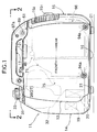
- Fig. 1 is a side view of the entire arrangement of an engine generator.
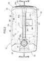
- Fig. 2 is a view taken along a line 2-2 in Fig. 1.
- Fig. 3 is a sectional view taken along a line 3-3 in Fig. 2.
- Fig. 4 is a sectional view taken along a line 4-4 in Fig. 2.
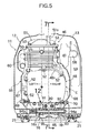
- Fig. 5 is a sectional view taken along a line 5-5 in Fig. 3.
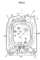
- Fig. 6 is a view taken in a direction of an arrow 6 in Fig. 3.
- Fig. 7 is a view taken along a line 7-7 in Fig. 5.
- Fig. 8 is a sectional view taken along a line 8-8 in Fig. 3.
- Fig. 9 is a view taken in a direction of an arrow 9 in Fig. 3.
- Fig. 10 is an enlarged view of an area indicated by 10 in Fig. 3.
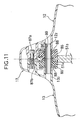
- Fig. 11 is a sectional view taken along a line 11-11 in Fig. 10.
- Fig. 12 is an enlarged view of an area indicated by 12 in Fig. 5.
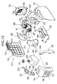
- Fig. 13 is an exploded perspective view of the engine generator.
- Figs. 1 to 13 show an embodiment of the present invention.
- a case 11 made of a synthetic resin, which forms an outer profile of an engine generator for generating electric power by driving a generator G with an engine E is comprised of a left side cover 12, a right side cover 13, a front cover 14, a rear cover 15 and an undercover 16.
- a carrying handle 17 for carrying the engine generator is provided at upper portions of the left and right side covers 12 and 13 integrally formed therewith, and reinforcing ribs 17 1 are formed in a lattice shape within the carrying handle 17 (see Figs. 3 and 4).
- a spark plug replacing lid 12 1 is formed on the left side cover 12, and slit-shaped cooling-air introducing ports 12 3 are defined in the left side cover 12.
- a maintenance lid 13 1 is formed on the right side cover 13.
- the front cover 14 is provided with an operating panel 18, a control unit 19 mounted at a rear portion of the operating panel 18 for controlling the operations of the engine E and the generator G, and an inverter unit 20 mounted in the rear of the control unit 19 for controlling an output frequency from the generator G.
- the rear cover 15 is provided with an exhaust gas discharge port 15 1 for discharging exhaust gas from the engine E, and a cooling-air discharge port 15 2 for discharging cooling-air from the case 11.
- the undercover 16 is provided with four support legs 21 made of a rubber, which are intended to abut against a ground surface or a floor surface upon placement of the engine generator.
- the operating panel 18, the control unit 19 and the inverter unit 20 forming a control system of the engine generator are arranged in a collected manner on the front cover 14. Therefore, not only the length of a wire harness can be shortened, but also the maintenance of the control system can be carried out collectively by only removing the front cover 14.
- the case 11 is provided at its front portion with a left reinforcing frame 26 and a right reinforcing frame 27, each of which is formed of FRP into an inverted L-shape.
- the left reinforcing frame 26 fixed at its lower end to a left side of the undercover 16 by a bolt 28, rises upwards and laterally inwards along an inner surface of the left side cover 12, and has an upward-folded mounting portion 26 1 formed at an upper end thereof.
- the left and right frames 26 and 27 form a gate-shape as a whole.
- the superposed mounting portions 26 1 and 27 1 are clamped commonly by threadedly fitting a bolt 30a inserted therein from the side of the left side cover 12 into an embedded nut 30b of the right side cover 13, in a condition in which they have been sandwiched between the left and right side covers 12 and 13 in front of the carrying handle 17 (see Fig. 8).
- a seal member 31 made of a rubber is mounted at a location in which the upper surfaces of the left and right covers 12 and 13 and the front cover 14 are joined together.
- a fuel tank 32 is disposed above the inverter unit 20 and has an oil supply port 32 1 closed by a cap 33 which is detachably mounted to extend upwards through an opening 31 1 in the seal member 31.
- the fuel tank 32 is positioned, so that it is not swung, by loosely fitting projections 32 2 and 32 3 provided on both of the left and right side faces of the fuel tank 32 into fuel tank support portions 26 2 and 27 2 defined in the left and right reinforcing frames 26 and 27.
- the fuel tank 32 is supported in such a manner that it is sandwiched from the left and right between the left and right side covers 12 and 13. Therefore, the fuel tank 32 can be demounted by only separating the left and right side covers 12 and 13 from each other without an operation such as detachment of the bolt. Moreover, since the fuel tank 32 is surrounded by the left and right reinforcing frames 26 and 27, the fuel tank 32 can be protected from a shock applied thereto from the outside. The left and right reinforcing frames 26 and 27 do not cover the entire engine generator and hence, a substantial increase in weight is not brought about.
- An electrically-operated fuel pump 35 is mounted on an upper surface of an upper portion of the right reinforcing frame 27 for feeding the fuel in the fuel tank 32 to the engine E, and a fuel cock 36 and an engine switch 42 are mounted on an outer side of a lower portion of the right reinforcing frame 27 for cutting off the feeding of the fuel to the engine E.
- a control knob 36 1 for opening and closing the fuel cock 36 passes through the right side cover 13 and is exposed to the outside. In this way, the fuel pump 35 and the fuel cock 36 are supported utilizing the right reinforcing frame 27 and hence, a special support member is not required, thus resulting in a reduction in number of parts.
- the fuel tank 32, the fuel pump 35, the fuel cock 36 and the like comprising a fuel supply system, are supported in a collected manner on the left and right reinforcing frames 26 and 27 rather than on the left and right side frames 12 and 13. Therefore, for the purpose of maintenance of the fuel supply system, the left and right side frames 12 and 13 can be removed easily.
- reference character 37 is a fuel tube for supplying the fuel from the fuel tank 32 to the fuel cock 36; 38 is a fuel tube for supplying the fuel from the fuel cock 36 to the fuel pump 35; 39 is a fuel tube for supplying the fuel from the fuel pump 35 to a carburetor 41; and 40 is a tube for transmitting the pulsation of an internal pressure in a crankcase of the engine E to a diaphragm (not shown) within the fuel pump 35 to drive the fuel pump 35.
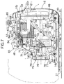
- a power generating unit 46 comprising the engine E and the generator G connected integrally to each other, will be described below with reference to Figs. 5 to 13.
- the 4-cycle, one-cylinder engine E has a crankshaft 47 with an axis disposed longitudinally and includes a crankcase 48, a cylinder block 49, a cylinder head 50 and a head cover 51.
- the crankcase 48 is divided into two front and rear portions along a parting line 48 1 inclined at 45° with respect to the axis of the crankshaft 47.
- the front portion of the crankcase 48, the cylinder block 49 and the cylinder head 50 are formed integrally with one another.
- the head cover 51 is detachably coupled to the cylinder head 50 by four bolts 53.
- the generator G of an outer rotor type is mounted in a cantilever manner at the axial end of the crankshaft 47 protruding forwards from the crankcase 48, and is comprised of a stator having coils 54 fixed to a front surface of the crankcase 48, and a rotor having permanent magnets 56 which are fixed to an inner peripheral surface of a flywheel 55 fixed to the crankshaft 48, and which are opposed to outer peripheral surfaces of the coils 54.
- a cooling fan 57 is fixed coaxially to a front surface of the flywheel 55.
- the carburetor 41 is disposed on a right side of the cylinder head 50 of the engine E, and an air cleaner 59 (see Figs.
- a box-shaped muffler 61 is connected to a rear end of an exhaust pipe 60 extending rearwards from a left side of the cylinder head 50 of the engine E, and is fixed to a rear surface of the engine E by three bolts 62, 62 and 63 (see Fig. 6).
- An exhaust port 61 1 is defined in a rear surface of the muffler 61 to face the exhaust gas discharge port 15 1 in the rear cover 15 (see Fig. 7).
- a shroud 66 made of a synthetic resin and covering the periphery of the engine E is divided into a left shroud half 67 and a right shroud half 68.
- the left shroud half 67 is fastened to left sides of the crankcase 48 and the cylinder block 49 of the engine E by two bolts 69, 69 (see Figs. 3 and 5)
- the right shroud half 68 is fastened to right sides of the crankcase 48 and the cylinder block 49 of the engine E by two bolts 70, 70 (see Figs. 4 and 5).
- the shroud 66 has front and rear surfaces which open.
- the outer periphery of the muffler 61 is fitted into the opening in the rear surface with a gap left therebetween, and a fan cover 71 made from aluminum by a die-casting process is fitted to cover the opening in the front surface.
- the fan cover 71 covers the generator G and the cooling fan 57 and is fastened at its upper portion to the cylinder head 50 of the engine E by a bolt 72 and at its lower portion to the crankcase 48 of the engine E by two bolts 73, 73 (see Figs. 7 and 8).
- a recoil starter 75 is fixed to a central opening in the fan cover 71 by three bolts 74.
- the recoil starter 75 includes a reel 77 rotatably carried on a recoil starter cover 76, a cable 78 wound at one end thereof around the reel 77 and passing at the other end thereof through the right reinforcing frame 27 and the right cover 13, a control knob 79 mounted at the other end of the cable 78, and a driving member 80 mounted on the reel 77 and capable of being brought into and out of engagement with a driven member 57 1 integral with the cooling fan 57 (see Figs. 7 and 8).
- Cooling-air introducing ports 76 1 are defined in the recoil starter cover 76, and a cooling-air introducing port 64 is also defined between a lower end of the recoil starter cover 76 and a front lower portion of the shroud 66 (see Fig. 7).
- the driving member 80 actuated by a cam mechanism (not shown) can be brought into engagement with the driven member 57 1 to rotate the cooling fan 57, whereby the crankshaft 47 connected to the cooling fan 57 through the flywheel 55 can be cranked or rotated to start the engine E.
- the control knob is released, the driving member 80 is brought out of engagement with the driven member 57 1 , whereby the reel 77 is revered into the original position under the action of a return spring (not shown), while winding-up the cable 78 therearound.
- a rectangular opening 81 1 is defined, so that it is surrounded by the left shroud half 67, the right shroud half 68 and the fan cover 71, and the head cover 51 of the engine E passes through the opening 81 1 and protrudes to the outside of the shroud 66.
- An air baffle plate 51 1 is integrally formed at a front portion of the head cover 51 and extends in such a manner that it is inclined forward and downward.
- a space forming an air passage 82 is defined between the air baffle plate 51 1 and a notch 50 1 (see Fig. 9) defined in an upper surface of a front portion of the cylinder head 50.
- An opening in an upper end of the guide member 84 is closed by a detachable cap 84 1 .
- An ignition coil 65 is mounted at an upper end of the fan cover 71 in proximity to the spark plug 83.
- the guide member 84 faces the spark plug replacing lid 12 1 of the left side cover 12 (see Fig. 2) and hence, the maintenance of the spark plug 83 can be carried out through the spark plug attaching and detaching bore 51 2 only by opening the spark plug replacing lid 12 1 and removing the cap 4 1 .
- the maintenance of a valve operating mechanism covered with the head cover 51 e.g., the regulation of the tappet clearance and the like can be carried out easily, without removal of the left and right shroud halves 67 and 68, only by removing the head cover 51 exposed from the shroud 66.
- a longitudinally extending plate-shaped support 51 3 is projectingly provided on an upper surface of the head cover 51 of the engine.
- a pair of left and right rubber bushings 85, 85 are fitted into a circular support bore 51 4 centrally defined in the support 51 3 , and a collar 86 is inserted through the inside of the bushings 85, 85.
- a bolt 87a is inserted at a rear portion of the carrying handle 17 from the side of the left side cover 12 and fastened to an embedded nut 87b provided in the right side cover 13.
- Bosses 12 2 and 13 2 are projectingly provided on the inner surfaces of the left and right side covers 12 and 13 in the vicinity of the bolt 87a.
- Washers 88, 88 are disposed at ends of the left and right rubber bushings 85, 85, and in this state, a connecting pin 89 passing through the washers 88, 88 and the collar 86, is fitted at its opposite ends over the bosses 12 2 and 13 2 of the left and right side covers 12 and 13, respectively.
- a mounting bracket 91 is fixed to a rear lower portion of the crankcase 48 of the engine E by two bolts 90, 90.
- the mounting bracket 91 protrudes out of the opening 81 2 in the rear lower portion of the shroud 66, and a pair of left and right rubber bushings 92, 92 are fitted over the bracket 91.
- a pair of left and right mounting ribs 16 1 , 16 1 are formed on an upper surface of a rear portion of the undercover 16 of the case 11, and the rubber bushings 92, 92 are supported on an outer periphery of a central portion of a collar 93 bridging between the pair of mounting ribs 16 1 , 16 1 , with a pair of left and right washers 95, 95 interposed therebetween.
- the rear lower portion of the engine exposed from the shroud 66 is resiliently supported on the undercover 16 with the rubber bushings 92, 92 interposed therebetween by fastening a bolt 94a inserted from the boss 13 3 of the right side cover 13 and passing through the collar 93 to an embedded nut 94b provided in the boss 12 3 of the left side cover 12.
- a mounting bracket 71 1 is integrally formed at a lower portion of the fan cover 71 and resiliently supported through a bolt 94a on a pair of left and right mounting ribs 16 2 , 16 2 projectingly provided on an upper surface of a front portion of the undercover 16.
- the structure for supporting the mounting bracket 71 1 is the same as the structure for supporting the mounting bracket 91 described with reference to Fig. 5.
- the head cover 51 located on the upper side is resiliently supported on the carrying handle 17 through the rubber bushing 85, 85;
- the crankcase 48 located on the rear and lower side is resiliently supported on the undercover 16 through the rubber bushings 92, 92;
- the fan cover 71 located on the front and lower side is resiliently supported on the undercover 16 through the rubber bushings 92, 92. Therefore, the weight of the power-generating unit 46 can be dispersed to various portions of the case 11 to prevent a load from being concentrated on a small portion of the case 11.
- the vibration absorbing effect of the rubber bushings 85, 85 and 92 makes it possible not only to prevent the vibration of the engine E from being transmitted to the carrying handle 17, but also to prevent the case 11 from being resonant by the vibration of the engine E.
- the carrying handle 17 when the carrying handle 17 is lifted to carry the engine generator, most of the weight of the power generating unit 46 including the engine E and the generator G is supported from the support 51 3 of the head cover 51 via the rubber bushings 85, 85, the connecting pin 89 and the bosses 12 2 and 13 2 onto the carrying handle 17 of the case 11. Namely, the power-generating unit 46 is brought into a state in which it hangs down on the carrying handle 17, and thus, it is not necessary to support the weight of the power-generating unit 46 by the case 11 itself. Therefore, the thickness of the case 11 connected below the carrying handle 17 can be reduced, thereby not only providing a reduction in weight of the power-generating unit 46, but also providing a substantial increase in degree of freedom of the design such as the shape and the material of the case 11.
- the entire height of the engine generator can be kept to a low level, as compared with a case where the head cover 51 is covered completely with the shroud 66, and the shroud 66 is supported at its upper end on the carrying handle 17.
- the load can be dispersed to the front and rear of the carrying handle 17 without the bearing of the load by the left and right side covers 12 and 13, whereby the bending load applied to the carrying handle 17 and a portion of the case 11, in the vicinity of the carrying handle 17 can be alleviated, because the front portion of the undercover 16 supporting the lower portion of the power-generating unit 46, namely, the lower portion of the fan cover 71 and the lower portion of the crankcase 48, is connected to the front portion of the carrying handle 17 through the left and right reinforcing frames 26 and 27 each having a high rigidity.
- the fan cover 71 made from aluminum by a die-casting process, is fastened to the crankcase 48 and the cylinder head 50 in a blocking manner, and the mounting bracket 91 of the crankcase 48 protruding from the shroud 66 covering the outer periphery of the fan cover 71, the crankcase 48 and the cylinder head 50, and the mounting bracket 71 1 of the fan cover 71, are supported on the mounting ribs 16 1 , 16 1 ; 16 2 , 16 2 of the undercover 16 through the rubber bushings 92, 92. Therefore, the power-generating unit 46 can be supported reliably on the undercover 16 without a special support member such as an engine bed.
- the left and right side covers 12 and 13 can be separated from the undercover 16 by only removing the four bolts 30a, 87a, 94a, 94a. Therefore, the engine E and the generator G can be exposed without moving the engine generator sideways, whereby the maintenance thereof can be carried out easily.
- the rubber bushings 85 and 92 correspond to vibration-damping members of the present invention.
- the cooling fan 57 mounted on the flywheel 55 of the generator G is rotated within the shroud 66.
- external air passes through the cooling-air introducing ports 14 1 and 14 2 (see Figs. 3 and 4) in the front cover 14 and is introduced as cooling air into the case 11.
- Reference character 14 3 is a guide for the cooling air introduced through cooling-air introducing port 14 2 .
- the cooling air is introduced through the cooling-air introducing ports 76 1 defined in the recoil starter cover 76 and the cooling-air introducing port 64 defined below the recoil starter cover 76 into the fan cover 71 and the shroud 66 to cool the generator G, the engine E and the muffler 61 accommodated in the shroud 66. Thereafter, the cooling air passes through the gap between the shroud 66 and the muffler 61 and is discharged through the cooling-air discharge port 15 2 to the outside of the case 11. Openings 96 (see Fig. 7) are defined in the flywheel 55 and the cooling fan 57, and the air heated within the generator G is drawn through the openings 96 into the shroud 66.
- the flow of the cooling air within the shroud 66 can be smoothed to enhance the cooling effect, because the air baffle plate 51 1 formed integrally on the head cover 51 of the engine E, defines the air passage 82 by cooperation with the fan cover 71 and the left and right shroud halves 67 and 68. Moreover, the cooling air flows directly through the inside of the fan cover 71 made from aluminum by the die-casting process and is coupled to the engine E and hence, the fan cover 71 exhibits a heat sink function to enhance the performance of cooling the engine E.
- the cooling air flows substantially rectilinearly from the front to the rear within the case 11, it cools the generator G which is a heat-generating member, the engine E and the muffler 61. Therefore, it is possible not only to keep the resistance to the flow of the cooling air to enhance the cooling efficiency, but also to keep the number of the cooling fans 57 to one, to reduce the number of parts. Noises emitted by the engine E and the cooling fan 57 are reduced effectively by the shroud 66 and the case 11 which doubly covers the engine E and the cooling fan 57, thereby enabling the quiet operation of the engine generator.
- the rubber bushings 85 and 92 have been illustrated as the resilient members in the embodiment, but another resilient member such as a spring may be used.
- the carrying handle 17 is a portion of the case 11, but may be formed as a separate member and attached to the case 11.
Landscapes
- Engineering & Computer Science (AREA)
- General Engineering & Computer Science (AREA)
- Mechanical Engineering (AREA)
- Chemical & Material Sciences (AREA)
- Combustion & Propulsion (AREA)
- Acoustics & Sound (AREA)
- Physics & Mathematics (AREA)
- Aviation & Aerospace Engineering (AREA)
- Motor Or Generator Frames (AREA)
- Body Structure For Vehicles (AREA)
- Arrangement Or Mounting Of Propulsion Units For Vehicles (AREA)
- Connection Of Motors, Electrical Generators, Mechanical Devices, And The Like (AREA)
- Cylinder Crankcases Of Internal Combustion Engines (AREA)
- Coupling Device And Connection With Printed Circuit (AREA)
Priority Applications (2)
| Application Number | Priority Date | Filing Date | Title |
|---|---|---|---|
| EP05023638A EP1621739B1 (de) | 1999-07-12 | 2000-07-12 | Brennkraftmaschine und Generatorkombination |
| EP05023639A EP1621740B1 (de) | 1999-07-12 | 2000-07-12 | Brennkraftmaschine und Generatorkombination |
Applications Claiming Priority (2)
| Application Number | Priority Date | Filing Date | Title |
|---|---|---|---|
| JP19783199 | 1999-07-12 | ||
| JP19783199A JP3696441B2 (ja) | 1999-07-12 | 1999-07-12 | エンジン発電機 |
Related Child Applications (4)
| Application Number | Title | Priority Date | Filing Date |
|---|---|---|---|
| EP05023638A Division EP1621739B1 (de) | 1999-07-12 | 2000-07-12 | Brennkraftmaschine und Generatorkombination |
| EP05023639A Division EP1621740B1 (de) | 1999-07-12 | 2000-07-12 | Brennkraftmaschine und Generatorkombination |
| EP05023639.7 Division-Into | 2005-10-28 | ||
| EP05023638.9 Division-Into | 2005-10-28 |
Publications (3)
| Publication Number | Publication Date |
|---|---|
| EP1069295A2 true EP1069295A2 (de) | 2001-01-17 |
| EP1069295A3 EP1069295A3 (de) | 2002-03-20 |
| EP1069295B1 EP1069295B1 (de) | 2005-12-28 |
Family
ID=16381079
Family Applications (3)
| Application Number | Title | Priority Date | Filing Date |
|---|---|---|---|
| EP05023638A Expired - Lifetime EP1621739B1 (de) | 1999-07-12 | 2000-07-12 | Brennkraftmaschine und Generatorkombination |
| EP05023639A Expired - Lifetime EP1621740B1 (de) | 1999-07-12 | 2000-07-12 | Brennkraftmaschine und Generatorkombination |
| EP00305912A Expired - Lifetime EP1069295B1 (de) | 1999-07-12 | 2000-07-12 | Brennkraftmaschine-Generator-Kombination |
Family Applications Before (2)
| Application Number | Title | Priority Date | Filing Date |
|---|---|---|---|
| EP05023638A Expired - Lifetime EP1621739B1 (de) | 1999-07-12 | 2000-07-12 | Brennkraftmaschine und Generatorkombination |
| EP05023639A Expired - Lifetime EP1621740B1 (de) | 1999-07-12 | 2000-07-12 | Brennkraftmaschine und Generatorkombination |
Country Status (7)
| Country | Link |
|---|---|
| US (1) | US6378469B1 (de) |
| EP (3) | EP1621739B1 (de) |
| JP (1) | JP3696441B2 (de) |
| KR (1) | KR100394383B1 (de) |
| CN (1) | CN1117921C (de) |
| DE (3) | DE60043715D1 (de) |
| TW (1) | TW432163B (de) |
Cited By (12)
| Publication number | Priority date | Publication date | Assignee | Title |
|---|---|---|---|---|
| EP1995431A1 (de) * | 2007-05-22 | 2008-11-26 | Yunfeng Ma | Tragbarer Generator |
| GB2502400A (en) * | 2012-01-04 | 2013-11-27 | Ini Power Systems Inc | Flexible fuel generator and methods of use thereof |
| WO2013182836A1 (en) * | 2012-06-08 | 2013-12-12 | Amir Golad | Generator assembly and modular power supply system |
| US8810053B2 (en) | 2012-02-29 | 2014-08-19 | Ini Power Systems, Inc. | Method and apparatus for efficient fuel consumption |
| US9188033B2 (en) | 2012-01-04 | 2015-11-17 | Ini Power Systems, Inc. | Flexible fuel generator and methods of use thereof |
| USD794562S1 (en) | 2012-12-20 | 2017-08-15 | Ini Power Systems, Inc. | Flexible fuel generator |
| EP3219952A1 (de) * | 2016-03-15 | 2017-09-20 | Honda Motor Co., Ltd. | Motorbetriebene arbeitsmaschine |
| US9909534B2 (en) | 2014-09-22 | 2018-03-06 | Ini Power Systems, Inc. | Carbureted engine having an adjustable fuel to air ratio |
| US10030609B2 (en) | 2015-11-05 | 2018-07-24 | Ini Power Systems, Inc. | Thermal choke, autostart generator system, and method of use thereof |
| USD827572S1 (en) | 2015-03-31 | 2018-09-04 | Ini Power Systems, Inc. | Flexible fuel generator |
| CN110529239A (zh) * | 2019-08-13 | 2019-12-03 | 苏州帕瓦麦斯动力有限公司 | 便携逆变汽油发电机组 |
| EP4365424A4 (de) * | 2021-10-04 | 2024-11-20 | Sumitomo Riko Company Limited | Abdeckung für kraftfahrzeugmotor |
Families Citing this family (41)
| Publication number | Priority date | Publication date | Assignee | Title |
|---|---|---|---|---|
| JP4071443B2 (ja) * | 2001-02-14 | 2008-04-02 | 本田技研工業株式会社 | 携帯用エンジン作業機 |
| JP4563625B2 (ja) * | 2001-09-03 | 2010-10-13 | 本田技研工業株式会社 | エンジン発電機 |
| JP3579675B2 (ja) * | 2002-02-20 | 2004-10-20 | 川崎重工業株式会社 | 強制空冷式の小型エンジン |
| JP3886002B2 (ja) | 2002-03-27 | 2007-02-28 | ヤマハ発動機株式会社 | エンジン発電機 |
| US20050145213A1 (en) * | 2002-09-06 | 2005-07-07 | Boris Schapiro | Electric power generator assembly |
| KR100735648B1 (ko) * | 2003-07-10 | 2007-07-06 | 혼다 기켄 고교 가부시키가이샤 | 엔진 구동식 발전기 |
| JP4243151B2 (ja) * | 2003-07-10 | 2009-03-25 | 本田技研工業株式会社 | エンジン駆動式発電機 |
| JP4210565B2 (ja) * | 2003-08-04 | 2009-01-21 | 本田技研工業株式会社 | 可搬式エンジンポンプ |
| MY143612A (en) * | 2005-06-23 | 2011-06-15 | Honda Motor Co Ltd | Air-cooled engine |
| USD567175S1 (en) | 2006-08-25 | 2008-04-22 | Briggs & Stratton Corporation | Inverter generator |
| CN100402819C (zh) * | 2006-09-12 | 2008-07-16 | 重庆重客工贸发展有限公司 | 两用燃料携带式发电机组 |
| US7559297B2 (en) * | 2007-08-17 | 2009-07-14 | Yunfeng Ma | Portable Engine |
| US7770692B2 (en) * | 2007-09-14 | 2010-08-10 | Gm Global Technology Operations, Inc. | Engine acoustic treatment |
| AU2012216658B2 (en) | 2011-09-13 | 2016-09-15 | Black & Decker Inc | Method of reducing air compressor noise |
| US8899378B2 (en) | 2011-09-13 | 2014-12-02 | Black & Decker Inc. | Compressor intake muffler and filter |
| CN102383926B (zh) | 2011-10-23 | 2013-02-06 | 浙江乐恒动力科技有限公司 | 一种发动机驱动的箱式发电机 |
| JP5840577B2 (ja) * | 2012-07-30 | 2016-01-06 | 本田技研工業株式会社 | 携帯型エンジン発電機 |
| JP5474155B1 (ja) * | 2012-10-16 | 2014-04-16 | 株式会社小松製作所 | 排気処理ユニット、排気処理ユニットの取り付け及び取り外し方法 |
| JP5819344B2 (ja) | 2013-04-30 | 2015-11-24 | 富士重工業株式会社 | 携帯型エンジン |
| CN103291447B (zh) * | 2013-05-24 | 2015-10-21 | 宁波顶和电子有限公司 | 一种智能节油便携式发电机组 |
| US10294858B2 (en) | 2013-08-29 | 2019-05-21 | Polaris Industries Inc. | Portable generator |
| CN103486411A (zh) * | 2013-09-23 | 2014-01-01 | 浙江格林雅动力科技有限公司 | 一种应用于数码发电机组中的托板式底盘 |
| JP6170427B2 (ja) * | 2013-12-27 | 2017-07-26 | 株式会社Subaru | 携帯型エンジン |
| US9322371B2 (en) * | 2014-04-09 | 2016-04-26 | Champion Engine Technology, LLC | Slide-in mountable fuel pump assembly |
| US10060343B2 (en) * | 2014-12-09 | 2018-08-28 | Generac Power Systems, Inc. | Air flow system for an enclosed portable generator |
| JP5966058B2 (ja) * | 2015-05-11 | 2016-08-10 | 富士重工業株式会社 | 携帯型エンジン |
| WO2017030034A1 (ja) | 2015-08-14 | 2017-02-23 | 株式会社プロドローン | 発電装置およびこれを備える無人航空機 |
| US11111913B2 (en) | 2015-10-07 | 2021-09-07 | Black & Decker Inc. | Oil lubricated compressor |
| US9553491B2 (en) * | 2016-03-02 | 2017-01-24 | Caterpillar Inc. | Alternator mounting assembly |
| JP6653196B2 (ja) * | 2016-03-10 | 2020-02-26 | 本田技研工業株式会社 | 燃料タンク付き作業機 |
| JP6628651B2 (ja) * | 2016-03-15 | 2020-01-15 | 本田技研工業株式会社 | エンジン駆動作業機 |
| KR102011121B1 (ko) * | 2018-02-09 | 2019-08-16 | (주)디오코인터내셔날 | 잔여 연료량 확인 수단이 구비된 이동식 발전기 |
| WO2019187083A1 (ja) * | 2018-03-30 | 2019-10-03 | 本田技研工業株式会社 | 汎用エンジン |
| JP2020108318A (ja) * | 2018-12-28 | 2020-07-09 | 本田技研工業株式会社 | 発電装置 |
| USD1085010S1 (en) | 2023-10-11 | 2025-07-22 | Northern Tool & Equipment Company, Inc. | Generator assembly |
| USD1085009S1 (en) | 2023-10-11 | 2025-07-22 | Northern Tool & Equipment Company, Inc. | Generator assembly |
| USD1085007S1 (en) | 2023-10-11 | 2025-07-22 | Northern Tool & Equipment Company, Inc. | Generator assembly |
| USD1085008S1 (en) | 2023-10-11 | 2025-07-22 | Northern Tool & Equipment Company, Inc. | Generator assembly |
| USD1085006S1 (en) | 2023-10-11 | 2025-07-22 | Northern Tool & Equipment Company, Inc. | Generator assembly |
| USD1085012S1 (en) | 2023-10-11 | 2025-07-22 | Northern Tool & Equipment Company, Inc. | Generator assembly |
| USD1085011S1 (en) | 2023-10-11 | 2025-07-22 | Northern Tool & Equipment Company, Inc. | Generator assembly |
Citations (1)
| Publication number | Priority date | Publication date | Assignee | Title |
|---|---|---|---|---|
| JPS6421399A (en) | 1987-06-18 | 1989-01-24 | Westinghouse Electric Corp | Fuel rod takeoff apparatus, withdrawal of fuel rod, capacity reducer, use of extrusion rod and transfer of fuel rod |
Family Cites Families (11)
| Publication number | Priority date | Publication date | Assignee | Title |
|---|---|---|---|---|
| GB2139429B (en) * | 1983-03-18 | 1986-08-13 | Honda Motor Co Ltd | Portable generators |
| JPS60209634A (ja) * | 1984-04-02 | 1985-10-22 | Honda Motor Co Ltd | 可搬型エンジン作業機 |
| JPS6140425A (ja) * | 1984-07-31 | 1986-02-26 | Yanmar Diesel Engine Co Ltd | ケ−ス収容型エンジン発電機 |
| JPS6192392A (ja) * | 1984-10-09 | 1986-05-10 | 本田技研工業株式会社 | 携帯用エンジン作業機のフレ−ム構造 |
| JPH0128270Y2 (de) * | 1984-10-09 | 1989-08-29 | ||
| US4677940A (en) * | 1985-08-09 | 1987-07-07 | Kohler Co. | Cooling system for a compact generator |
| US4827147A (en) | 1986-11-12 | 1989-05-02 | Honda Giken Kogyo Kabushiki Kaisha | Engine-powered portable working apparatus |
| US4907546A (en) * | 1987-12-02 | 1990-03-13 | Kubota Ltd. | Air-cooled type cooling system for engine working machine assembly |
| JPH03111657A (ja) * | 1989-09-22 | 1991-05-13 | Yamaha Motor Co Ltd | 携帯用ガスエンジン作業機 |
| JP3731687B2 (ja) * | 1996-12-10 | 2006-01-05 | 本田技研工業株式会社 | 防護枠型内燃機関作業機 |
| JPH11190220A (ja) * | 1997-12-25 | 1999-07-13 | Suzuki Motor Corp | 2系統燃料発電機 |
-
1999
- 1999-07-12 JP JP19783199A patent/JP3696441B2/ja not_active Expired - Lifetime
-
2000
- 2000-07-10 KR KR10-2000-0039306A patent/KR100394383B1/ko not_active Expired - Lifetime
- 2000-07-10 US US09/613,590 patent/US6378469B1/en not_active Expired - Lifetime
- 2000-07-11 TW TW089113777A patent/TW432163B/zh not_active IP Right Cessation
- 2000-07-12 EP EP05023638A patent/EP1621739B1/de not_active Expired - Lifetime
- 2000-07-12 DE DE60043715T patent/DE60043715D1/de not_active Expired - Lifetime
- 2000-07-12 DE DE60025083T patent/DE60025083T2/de not_active Expired - Lifetime
- 2000-07-12 EP EP05023639A patent/EP1621740B1/de not_active Expired - Lifetime
- 2000-07-12 EP EP00305912A patent/EP1069295B1/de not_active Expired - Lifetime
- 2000-07-12 CN CN00120481A patent/CN1117921C/zh not_active Expired - Lifetime
- 2000-07-12 DE DE60044100T patent/DE60044100D1/de not_active Expired - Lifetime
Patent Citations (1)
| Publication number | Priority date | Publication date | Assignee | Title |
|---|---|---|---|---|
| JPS6421399A (en) | 1987-06-18 | 1989-01-24 | Westinghouse Electric Corp | Fuel rod takeoff apparatus, withdrawal of fuel rod, capacity reducer, use of extrusion rod and transfer of fuel rod |
Cited By (21)
| Publication number | Priority date | Publication date | Assignee | Title |
|---|---|---|---|---|
| EP1995431A1 (de) * | 2007-05-22 | 2008-11-26 | Yunfeng Ma | Tragbarer Generator |
| US9995248B2 (en) | 2012-01-04 | 2018-06-12 | Ini Power Systems, Inc. | Flex fuel field generator |
| GB2502400A (en) * | 2012-01-04 | 2013-11-27 | Ini Power Systems Inc | Flexible fuel generator and methods of use thereof |
| GB2502400B (en) * | 2012-01-04 | 2014-06-04 | Ini Power Systems Inc | Flexible fuel generator and methods of use thereof |
| US9175601B2 (en) | 2012-01-04 | 2015-11-03 | Ini Power Systems, Inc. | Flex fuel field generator |
| US9188033B2 (en) | 2012-01-04 | 2015-11-17 | Ini Power Systems, Inc. | Flexible fuel generator and methods of use thereof |
| US8810053B2 (en) | 2012-02-29 | 2014-08-19 | Ini Power Systems, Inc. | Method and apparatus for efficient fuel consumption |
| US9450450B2 (en) | 2012-02-29 | 2016-09-20 | Ini Power Systems, Inc. | Method and apparatus for efficient fuel consumption |
| US10041403B2 (en) | 2012-06-08 | 2018-08-07 | Amir Golad | Generator assembly and modular power supply system |
| WO2013182836A1 (en) * | 2012-06-08 | 2013-12-12 | Amir Golad | Generator assembly and modular power supply system |
| USD794562S1 (en) | 2012-12-20 | 2017-08-15 | Ini Power Systems, Inc. | Flexible fuel generator |
| US9909534B2 (en) | 2014-09-22 | 2018-03-06 | Ini Power Systems, Inc. | Carbureted engine having an adjustable fuel to air ratio |
| USD827572S1 (en) | 2015-03-31 | 2018-09-04 | Ini Power Systems, Inc. | Flexible fuel generator |
| US10030609B2 (en) | 2015-11-05 | 2018-07-24 | Ini Power Systems, Inc. | Thermal choke, autostart generator system, and method of use thereof |
| US11274634B2 (en) | 2015-11-05 | 2022-03-15 | Ini Power Systems, Inc. | Thermal choke, autostart generator system, and method of use thereof |
| US11655779B2 (en) | 2015-11-05 | 2023-05-23 | The Dewey Electronics Corporation | Thermal choke, autostart generator system, and method of use thereof |
| EP3219952A1 (de) * | 2016-03-15 | 2017-09-20 | Honda Motor Co., Ltd. | Motorbetriebene arbeitsmaschine |
| CN107191268A (zh) * | 2016-03-15 | 2017-09-22 | 本田技研工业株式会社 | 发动机驱动作业机 |
| US10001055B2 (en) | 2016-03-15 | 2018-06-19 | Honda Motor Co., Ltd. | Engine-driven working machine housed in outer case with vibration isolating support |
| CN110529239A (zh) * | 2019-08-13 | 2019-12-03 | 苏州帕瓦麦斯动力有限公司 | 便携逆变汽油发电机组 |
| EP4365424A4 (de) * | 2021-10-04 | 2024-11-20 | Sumitomo Riko Company Limited | Abdeckung für kraftfahrzeugmotor |
Also Published As
| Publication number | Publication date |
|---|---|
| EP1621740B1 (de) | 2010-03-31 |
| EP1621739A3 (de) | 2009-03-25 |
| US6378469B1 (en) | 2002-04-30 |
| TW432163B (en) | 2001-05-01 |
| EP1621739A2 (de) | 2006-02-01 |
| EP1069295A3 (de) | 2002-03-20 |
| EP1621740A3 (de) | 2009-03-25 |
| CN1117921C (zh) | 2003-08-13 |
| EP1069295B1 (de) | 2005-12-28 |
| EP1621739B1 (de) | 2010-01-13 |
| KR20010015265A (ko) | 2001-02-26 |
| JP3696441B2 (ja) | 2005-09-21 |
| EP1621740A2 (de) | 2006-02-01 |
| KR100394383B1 (ko) | 2003-08-09 |
| JP2001027128A (ja) | 2001-01-30 |
| DE60025083T2 (de) | 2006-08-31 |
| DE60043715D1 (de) | 2010-03-04 |
| DE60044100D1 (de) | 2010-05-12 |
| CN1280243A (zh) | 2001-01-17 |
| DE60025083D1 (de) | 2006-02-02 |
Similar Documents
| Publication | Publication Date | Title |
|---|---|---|
| EP1069295B1 (de) | Brennkraftmaschine-Generator-Kombination | |
| EP1441115B1 (de) | Von einer Brennkraftmaschine getriebenes Gerät | |
| AU2004255716B2 (en) | Engine-driven electric generator | |
| JP4145912B2 (ja) | エンジン作業機 | |
| CN111433444B (zh) | 发动机装置 | |
| JP3871829B2 (ja) | エンジン発電機 | |
| JP3585773B2 (ja) | エンジン発電機 | |
| JP3754697B2 (ja) | エンジン作業機 | |
| JP4145911B2 (ja) | エンジン作業機 | |
| JP4145899B2 (ja) | エンジン発電機 | |
| JP2004353677A5 (de) | ||
| JP2005282581A5 (de) |
Legal Events
| Date | Code | Title | Description |
|---|---|---|---|
| PUAI | Public reference made under article 153(3) epc to a published international application that has entered the european phase |
Free format text: ORIGINAL CODE: 0009012 |
|
| AK | Designated contracting states |
Kind code of ref document: A2 Designated state(s): DE FR GB IT Kind code of ref document: A2 Designated state(s): AT BE CH CY DE DK ES FI FR GB GR IE IT LI LU MC NL PT SE |
|
| AX | Request for extension of the european patent |
Free format text: AL;LT;LV;MK;RO;SI |
|
| PUAL | Search report despatched |
Free format text: ORIGINAL CODE: 0009013 |
|
| AK | Designated contracting states |
Kind code of ref document: A3 Designated state(s): AT BE CH CY DE DK ES FI FR GB GR IE IT LI LU MC NL PT SE |
|
| AX | Request for extension of the european patent |
Free format text: AL;LT;LV;MK;RO;SI |
|
| 17P | Request for examination filed |
Effective date: 20020529 |
|
| AKX | Designation fees paid |
Free format text: DE FR GB IT |
|
| 17Q | First examination report despatched |
Effective date: 20040312 |
|
| GRAP | Despatch of communication of intention to grant a patent |
Free format text: ORIGINAL CODE: EPIDOSNIGR1 |
|
| RIN1 | Information on inventor provided before grant (corrected) |
Inventor name: TAMURA, MINORU Inventor name: HIRANUMA, JUNJI |
|
| GRAS | Grant fee paid |
Free format text: ORIGINAL CODE: EPIDOSNIGR3 |
|
| GRAA | (expected) grant |
Free format text: ORIGINAL CODE: 0009210 |
|
| AK | Designated contracting states |
Kind code of ref document: B1 Designated state(s): DE FR GB IT |
|
| REG | Reference to a national code |
Ref country code: GB Ref legal event code: FG4D |
|
| RIN1 | Information on inventor provided before grant (corrected) |
Inventor name: HIRANUMA, JUNJI Inventor name: TAMURA, MINORU |
|
| REF | Corresponds to: |
Ref document number: 60025083 Country of ref document: DE Date of ref document: 20060202 Kind code of ref document: P |
|
| ET | Fr: translation filed | ||
| PLBE | No opposition filed within time limit |
Free format text: ORIGINAL CODE: 0009261 |
|
| STAA | Information on the status of an ep patent application or granted ep patent |
Free format text: STATUS: NO OPPOSITION FILED WITHIN TIME LIMIT |
|
| 26N | No opposition filed |
Effective date: 20060929 |
|
| REG | Reference to a national code |
Ref country code: FR Ref legal event code: PLFP Year of fee payment: 17 |
|
| REG | Reference to a national code |
Ref country code: FR Ref legal event code: PLFP Year of fee payment: 18 |
|
| REG | Reference to a national code |
Ref country code: FR Ref legal event code: PLFP Year of fee payment: 19 |
|
| PGFP | Annual fee paid to national office [announced via postgrant information from national office to epo] |
Ref country code: FR Payment date: 20190619 Year of fee payment: 20 |
|
| PGFP | Annual fee paid to national office [announced via postgrant information from national office to epo] |
Ref country code: IT Payment date: 20190719 Year of fee payment: 20 Ref country code: DE Payment date: 20190702 Year of fee payment: 20 |
|
| PGFP | Annual fee paid to national office [announced via postgrant information from national office to epo] |
Ref country code: GB Payment date: 20190710 Year of fee payment: 20 |
|
| REG | Reference to a national code |
Ref country code: DE Ref legal event code: R071 Ref document number: 60025083 Country of ref document: DE |
|
| REG | Reference to a national code |
Ref country code: GB Ref legal event code: PE20 Expiry date: 20200711 |
|
| PG25 | Lapsed in a contracting state [announced via postgrant information from national office to epo] |
Ref country code: GB Free format text: LAPSE BECAUSE OF EXPIRATION OF PROTECTION Effective date: 20200711 |