EP1065166B2 - Grue téléscopique - Google Patents
Grue téléscopique Download PDFInfo
- Publication number
- EP1065166B2 EP1065166B2 EP00250210A EP00250210A EP1065166B2 EP 1065166 B2 EP1065166 B2 EP 1065166B2 EP 00250210 A EP00250210 A EP 00250210A EP 00250210 A EP00250210 A EP 00250210A EP 1065166 B2 EP1065166 B2 EP 1065166B2
- Authority
- EP
- European Patent Office
- Prior art keywords
- boom
- guy
- telescopic crane
- support
- boom structure
- Prior art date
- Legal status (The legal status is an assumption and is not a legal conclusion. Google has not performed a legal analysis and makes no representation as to the accuracy of the status listed.)
- Expired - Lifetime
Links
- 230000007704 transition Effects 0.000 claims description 3
- 210000002683 foot Anatomy 0.000 claims 4
- 238000010586 diagram Methods 0.000 description 7
- 238000005452 bending Methods 0.000 description 4
- 230000008859 change Effects 0.000 description 4
- 238000004873 anchoring Methods 0.000 description 2
- 230000008901 benefit Effects 0.000 description 2
- 230000000694 effects Effects 0.000 description 2
- 238000005516 engineering process Methods 0.000 description 2
- 230000006978 adaptation Effects 0.000 description 1
- 239000000969 carrier Substances 0.000 description 1
- 238000010276 construction Methods 0.000 description 1
- 230000009977 dual effect Effects 0.000 description 1
- 230000005484 gravity Effects 0.000 description 1
- 230000005855 radiation Effects 0.000 description 1
- 230000002787 reinforcement Effects 0.000 description 1
- 230000004044 response Effects 0.000 description 1
- 239000007787 solid Substances 0.000 description 1
- 230000007480 spreading Effects 0.000 description 1
- 230000000087 stabilizing effect Effects 0.000 description 1
- 239000000725 suspension Substances 0.000 description 1
Images

Classifications
-
- B—PERFORMING OPERATIONS; TRANSPORTING
- B66—HOISTING; LIFTING; HAULING
- B66C—CRANES; LOAD-ENGAGING ELEMENTS OR DEVICES FOR CRANES, CAPSTANS, WINCHES, OR TACKLES
- B66C23/00—Cranes comprising essentially a beam, boom, or triangular structure acting as a cantilever and mounted for translatory of swinging movements in vertical or horizontal planes or a combination of such movements, e.g. jib-cranes, derricks, tower cranes
- B66C23/62—Constructional features or details
- B66C23/82—Luffing gear
- B66C23/821—Bracing equipment for booms
- B66C23/826—Bracing equipment acting at an inclined angle to vertical and horizontal directions
- B66C23/828—Bracing equipment acting at an inclined angle to vertical and horizontal directions where the angle is adjustable
Definitions
- the invention relates to a telescopic crane, which consists of an undercarriage, a superstructure rotatably mounted thereon, a counterweight and a boom, which in turn has a main boom with a base box and at least one retractable and telescoping telescopic section.
- Telescopic cranes of the aforementioned type are known. That's how it shows DE 29 17 829 A1 a mobile crane with telescopic boom, which is pivotally articulated to a rotatable superstructure.
- the buoyancy of the crane is to be increased by a arranged on the superstructure of the vehicle crane receiving and lifting device is provided for an additional counterweight.
- the receiving and lifting device may have a back projecting support, which is suitably directed obliquely backwards and upwards and lowered for receiving the additional counterweight. It is pointed out that it would be of particular advantage if the support is connected to the telescopic boom above its articulation on the superstructure, as this causes a bending and buckling relief of the telescopic boom. To connect the support and the telescopic boom in particular a tensioning cable is proposed.
- a similar mobile crane with telescopic boom is in the DE 31 39 853 A1 described.
- a counterweight is provided, which can be brought to a corresponding projection by means of a mounted on the superstructure of the vehicle, backward, changeable in its inclination mast.
- the projection of the counterweight is controllable in response to the change in the center of gravity of the device due to the pivoting of the boom.
- the DE 38 38 975 C2 also shows a telescopic crane with a swing-out mast for a fixed to a hanger counterweight.
- the mast can be erected by a mast cylinder supported on the uppercarriage.
- the mast itself has a telescopic extension, at the top of a pivot point for a variable-length suspension device and a variable-length guying device for the variable-length boom is present.
- Telescopic cranes of the type described above are exposed in the extended state depending on the angle of attack different sized loads.
- the loads occurring in the clamping of the extended telescopic sections are an essential criterion for the maximum load.
- a so-called Superlift beach has been developed as a torque relief.
- the DE 31 13 763 A1 a basic embodiment of a telescopic crane, which allows a Superlift plante revealed.
- the DE 31 13 763 A1 In the field of articulation of a rocker cylinder for the main boom is in accordance with the DE 31 13 763 A1 arranged on the base box a transversely extending to the boom upwards jib.
- this guy trestle is connected by ropes or rope strands to the end of one of the telescopic sections and the foot of the main boom.
- the guy block consists of mutually spaced from the base box, upwardly extending struts, which are rigidly interconnected. Furthermore, it is stated that the guy clamp can be folded into a transport position on the base box.
- the connection between jib and boom foot is also proposed as unchangeable in length.
- a winch assembly is provided to vary the length of the cable provided between the jib and the telescopic boom.
- a control device for the winches for applying a predetermined tensile force on the guy trestle and the associated bracing can be provided.
- rocker plane is the plane in which the boom moves when it is pivoted about its horizontal pivot axis.
- the rocker plane is therefore perpendicular to the rocker axis of the boom.
- a realized telescopic crane with a "superlift” is, for example, from the company brochure: Mannesmann Demag printechnik; Demag AC 1600; 04/96, pages 5, 17 and 27 or even out DE 38 40 408 C2 known.
- a deductible on the base box Abspannbock is arranged.
- This guy trestle is connected to the head region or collar of one of the inner telescopic sections with a nearly length-independent bracing with the foot region of the main boom on the one hand and with a further bracing, which is usually variable in length.
- This stiffening arrangement is applicable to the basic unit alone, but also in connection with the arrangement of a rigid or rocking jib formed of lattice mast parts.
- a Superlift surge surge similar configuration is in the DE 297 20 972 U1 described.
- the telescopic boom shown here comprises a cable which engages the lower end of the boom and is guided in the manner of a guy bracket via a device which is assigned to the arm base body and whose angular position can be adjusted.
- the return rope used as a guy rope which serves to catch up the various telescopic shots of such a telescopic boom, exercise a stabilizing effect on the boom and in particular prevent unacceptable deflection of the telescopic boom.
- the guying device which takes over the function of a guy truss comprises a linkage, which can be swiveled about an articulation point on the telescopic boom or its base box.
- This crane boom in shell construction is known.
- This crane boom consists of a single torsionally rigid support body with preferably circular cross-section.
- the support body is over and / or under tensioned.
- an all-round overvoltage is provided, which is done with spars.
- one or more stem carriers are provided on the crane boom, at the radially outer ends of the spars are mounted and extending along the crane jib. This Stemong and the spars form a spatially fixed tension on the crane boom.
- this crane boom is intended for tower cranes.
- a boom with horizontal Seilabhis is from the DE 37 34 919 A1 known.
- the pivotable boom shown here has a plurality of parallel to the pivot axis extending trusses, which are guyed over cables.
- the trusses are ultimately the boom extension shown is nothing more than a strained carrier with solid trusses.
- this type of boom is provided for, for example, crawler mobile support frame.
- An outrigger of a crane for container operation is out of the DE 1 531 155 known.
- a luffing jib of a double-linkage luffing crane in which there are two beak-like spreadable arms forming the outer part of the boom which carry two head rollers or head roller groups.
- the arms are lockable in such a spreading position, in which the distance that the centers of the two rollers or groups of rollers from each other, is approximately equal to the distance between the centers of the container cross-wearing Hubseilge horr.
- the two arms are stiffened against each other in the coupled state and are positively and shear-resistant connected.
- the spreadable arms themselves are again, as already explained before, braced against bending over a guy clamp.
- the technical problem underlying the invention is to provide a telescopic crane, which can accommodate even in steep positions of the boom an increased load with less lateral deformation.
- a telescopic crane with undercarriage, rotatably mounted thereon superstructure, counterweight and a boom having a main boom with a base box and at least one retractable and telescoping telescopic section, at least one arranged on the boom guy support is present with is connected to a running substantially in the longitudinal direction of the boom clamping means and their inclination is tiltable to the rocker plane.
- the inclination of the guy support in a plane transversely and / or longitudinally to the longitudinal direction of the boom is variable.
- the The bracing support can be tilted relative to the rocker plane in planes that are perpendicular to it.
- the change in the inclination of the rocker plane can be adjustable stepwise or continuously by pivoting the at least one guy support.
- a simple embodiment provides that only a plurality of different stages of inclinations to the rocker plane are ingestible.
- Another embodiment may provide that the inclination in the range of greater than 0 ° to 90 ° relative to the rocker plane is adjustable, which allows a more accurate adaptation to the respective up position of the boom and the loads to be considered.
- At least one inclined relative to the seesaw leveling support is arranged, which is connected to a running substantially in the longitudinal direction of the boom clamping means, wherein the inclination of the guy support is chosen so that the lateral load acting on the boom partially or completely by the bracing is recorded.
- the inclination of the guy support can be transverse to the longitudinal direction or in the longitudinal direction or superimposed transversely to and in the longitudinal direction of the boom.
- two inclined guy supports are provided on the upper side of the respective boom element, wherein as a rule the angle inclination of both guy supports is the same. But it can also be different depending on the direction of the forces acting on the boom.
- the foot ends of both guy supports can be connected at a common location to the top of the boom, but also offset from one another.
- the foot end of at least one guy support is connected to the boom in the transition region between the upper side or the respective side wall.
- the exemplary arrangement has the advantage that, depending on the angular position of the guy supports, the proportion of the guy force acting in the lateral direction can be changed continuously or continuously.
- the effective clamping force is divided into a component Superlift réelle and a component lateral bracing.
- the second extreme position ie in the horizontal position, cause the two guy supports only a gain in both lateral directions.
- the respective free head end of the guy support is via a first clamping means optionally with the undercarriage, the uppercarriage, the foot area of the boom, the fixed or separately guided counterweight or the ground in the direction of the foot end of the boom and another clamping means with a selected location of the boom in Connected to the boom head.
- the respective desired angular position of the guy supports can be adjusted stepwise or continuously by pivoting the guy supports. This also allows an asymmetrical angle adjustment. This means that at an attacking lateral force only on one side of the respective guy supports is inclined more in the direction of lateral bracing, while the second guy support remains in a central position.
- the clamping means may be formed as a rope or as a rod.
- the clamping means or the clamping means can be arranged with and without bias. In the case of a bias voltage and a re-adjustable degree of tension, the clamping means cooperates with a tensioning device. Preferably, this is a winch or a piston-cylinder unit. But also the angle adjustment and / or the change in length of the guy support can be used in the sense of a clamping device.
- the clamping devices can be arranged optionally on the guy supports, on the boom, on the upper or undercarriage or on the counterweight.
- the guy supports are arranged on the main boom in the region of the basic box, in particular in the front region between the articulation of the luffing cylinder and the front storage.
- each guy support is preferably connected to a piston-cylinder unit supported on the base box.
- the guy support two spars, between which the winch can be arranged.
- the equipment of the telescopic boom can be supplemented with the arrangement of a rigid or rocking jib formed of lattice mast parts. Also to these boom elements, the proposed lateral bracing can be attached.
- the lateral bracing can be used particularly effectively if the crane is provided with a measuring device for detecting the lateral deformation of the boom. If the deformation exceeds a specified permissible value, the clamping device connected to the bracing is activated and the bracing is tensioned.
- the degree of lateral deformation can be determined directly or indirectly above crane sizes. For example, these are the rope tension, the rope length and rope elongation. But also on the forces acting on the boom in the form of the laterally occurring wind, solar radiation and the prevailing temperatures in the boom, a statement about the degree of lateral deformation can be made.
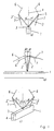
- FIG. 1 ac are shown as a schematic diagram of the possible arrangement of a tilted relative to the rocker guy support.
- the guy support 2 is preferably arranged on the upper side 3 of a jib element 1 shown symbolically here.
- This boom element 1 may be a base box or a shot of a main boom of a telescopic crane or the lattice mast element of a rigid or rockable jib.
- the drawn in the boom element 1 center axis 4 is in the ideal case, the rocker plane of the boom.
- the guy support 2 is inclined relative to the rocker plane at an angle ⁇ > 0.
- the dashed representation of the guy support 2 ' is intended to illustrate that the guy support 2 is also tilted towards the other side.
- the free end 5 of the Abspannstüzte 2 is connected to a tensioning means 6,7 preferably a side. Not shown here is the connection of the clamping means 6,7 with a boom arranged on the fixed point or a clamping device such as piston-cylinder unit or winch. A tensioning of the tensioning means 6, 7 can also be achieved without a tensioning device. On the one hand in such a way that the clamping means are arranged at a smaller or larger angle ⁇ .7 6 and then the guy support 2 is further inclined. Alternatively, it is also possible to form the guy support 2 telescopically and to achieve a degree of tension by changing the length.
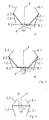
- FIG. 2 is also a schematic diagram showing the arrangement of two guy supports 2.1, 2.2.
- the peculiarity of this arrangement is that both guy supports 2.1,2.2 are arranged with only a single foot 8 on the upper side 3 of the boom element 1.
- the respective inclination angle ⁇ 1, ⁇ 2 may be the same or different.
- FIG. 3 In partial pictures ad of FIG. 3 are also shown as a schematic diagram of the possibility of the arrangement of two guy supports 2.1,2.2, which have a separate foot 8.1.8.2.
- the foot ends 8.1,8.2 are in the region of the upper side 3 of the jib element 1, while in the partial image b, the foot ends 8.1,8.2 are in the transition region from the upper side 3 to the respective side wall 9,9 '.
- part c the possibility is shown to arrange at least one foot 8.1 outside the boom element 1.
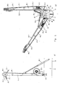
- a piston-cylinder unit 28.1,28.2 is ever provided, which is arranged at one end to the side wall 25 and the other end in the half range of the respective guy support 18.1.
- the tensioning means one rope 29.1 each is attached to one end of a rope thimble 31.1 on the head region of the guy support 18.1. From there it runs to the deflection point arranged in the direction of the boom head (also not shown here) and runs back over a deflection roller 30.1 arranged in the head area of the guy support 18.1 and from there to the winch 27.1.
- a guy clip 32.1 is arranged, which represents the rear-side securing for the respective guy support 18.1.
Landscapes
- Engineering & Computer Science (AREA)
- Mechanical Engineering (AREA)
- Jib Cranes (AREA)
Claims (32)
- Grue télescopique comprenant :- un chariot inférieur,- un chariot supérieur agencé sur celui-ci avec faculté de rotation,- un contrepoids,- une flèche (1) comportant une flèche principale avec un caisson de base (13) et au moins un tronçon télescopique rétractable et déployable à l'intérieur de celle-ci, et- au moins un pilier de haubanage (2, 2.1, 2.2, 18.1, 18.2) agencé sur la flèche (1) et qui est relié à un moyen de serrage (6, 7, 29.1, 29.2, 32.1, 32.2) s'étendant essentiellement en direction longitudinale de la flèche (1), et dont l'inclinaison (α, β) est modifiable par rapport au plan de basculement (4).
- Grue télescopique selon la revendication 1,
caractérisée en ce que l'inclinaison (α, β) du pilier de haubanage (2, 2.1, 2.2, 18.1, 18.2) est modifiable dans un plan perpendiculairement et/ou le long de la direction longitudinale de la flèche (1). - Grue télescopique selon l'une ou l'autre des revendications 1 et 2,
caractérisée en ce que l'inclinaison (α, β) du pilier de haubanage (2, 2.1, 2.2, 18.1, 18.2) est réglable dans un plan perpendiculairement et/ou le long de la direction longitudinale de la flèche (1), par échelons ou en continu, par un basculement du dit au moins un pilier de haubanage (2, 2.1, 2.2, 18.1, 18.2). - Grue télescopique selon l'une des revendications précédentes,
caractérisée en ce que l'extrémité du pied (8.1) d'au moins un des piliers de haubanage (2.1) est agencée sur un support (10) perpendiculaire à l'axe longitudinal de la flèche (1) et en porte-à-faux au-delà de celui-ci. - Grue télescopique selon l'une des revendications précédentes,
caractérisée en ce que l'extrémité de tête libre (5) d'un pilier de haubanage (2.1, 2.2, 18.1, 18.2) est reliée par un premier moyen de serrage (7, 32.1, 32.2) au choix au chariot supérieur, au chariot inférieur, à la zone du pied de la flèche (1), à un contrepoids stationnaire ou guidé séparément ou au sol en direction de l'extrémité du pied de la flèche (1), et par un autre moyen de serrage (6, 29.1, 29.2) à un emplacement sélectionné de la flèche principale (1) ou à une partie du prolongement de la flèche en direction de l'extrémité de tête de la flèche (1). - Grue télescopique selon la revendication 5,
caractérisée en ce que l'extrémité de tête libre du dit au moins un pilier de haubanage (18.1, 18.2) est reliée par un moyen de serrage (6, 29.1, 29.2) à la tête ou au col d'un des tronçons télescopiques intérieurs. - Grue télescopique selon la revendication 5,
caractérisée en ce que l'extrémité de tête libre dudit au moins un pilier de haubanage (18.1, 18.2) est reliée par un moyen de serrage (6, 29.1, 29.2) à une partie d'une flèche auxiliaire rigide ou basculante, se composant de zones de mâts en treillis. - Grue télescopique selon l'une des revendications précédentes,
caractérisée en ce que la longueur du pilier de haubanage (2, 2.1, 2.2, 18.1, 18.2) est modifiable. - Grue télescopique selon la revendication 8,
caractérisée en ce que la longueur du pilier de haubanage (2, 2.1, 2.2, 18.1, 18.2) est modifiable par échelons. - Grue télescopique selon la revendication 8,
caractérisée en ce que la longueur du pilier de haubanage (2, 2.1, 2.2, 18.1, 18.2) est modifiable en continu. - Grue télescopique selon l'une des revendications précédentes,
caractérisée en ce que le moyen de serrage (6, 7) est un câble (29.1, 29.2) et/ou une barre (32.1, 32.2). - Grue télescopique selon l'une des revendications précédentes, caractérisée en ce que le moyen de serrage (6, 7, 29.1, 29.2, 32.1, 32.2) coopère avec un dispositif de serrage (27.1, 27.2).
- Grue télescopique selon l'une des revendications précédentes,
caractérisée en ce qu'il est prévu des dispositifs de serrage à commande séparée (27.1, 27.2) pour le moyen de serrage (6, 7, 29.1, 29.2, 32.1, 32.2) de chaque pilier de haubanage (2, 2.1, 2.2, 18.1, 18.2). - Grue télescopique selon l'une ou l'autre des revendications 12 et 13,
caractérisée en ce que ledit au moins un dispositif de serrage (27.1, 27.2) est agencé sur le pilier de haubanage (18.1, 18.2), le chariot supérieur, le chariot inférieur, la flèche principale (1), le contrepoids ou un prolongement de la flèche. - Grue télescopique selon la revendication 12, 13 ou 14,
caractérisée en ce que le dispositif de serrage est un treuil (27.1, 27.2) ou une unité à piston-et-cylindre. - Grue télescopique selon l'une des revendications précédentes,
caractérisée en ce qu'une modification de l'inclinaison d'un pilier de haubanage (2, 2.1, 2.2, 18.1, 18.2) peut servir à tendre le moyen de serrage associé (6, 7, 29.1, 29.2, 32.1, 32.2). - Grue télescopique selon l'une des revendications précédentes,
caractérisée en ce qu'une modification de la longueur d'un pilier de haubanage (2, 2.1, 2.2, 18.1, 18.2) peut servir à tendre le moyen de serrage associé (6, 7, 29.1, 29.2, 32.1, 32.2). - Grue télescopique selon l'une des revendications précédentes,
caractérisée en ce que ledit au moins un pilier de haubanage (2) est agencé sur la face supérieure (3) de la flèche (1). - Grue télescopique selon l'une des revendications précédentes,
caractérisée en ce que une paire de piliers de haubanage (2.1, 2.2, 18.1, 18.2) sont agencés sur la flèche (1), un de ces piliers de haubanage (2.1, 18.1) étant inclinable sur un côté de la flèche (1), et l'autre pilier de haubanage (2.2, 18.2) étant inclinable sur l'autre côté de la flèche (1). - Grue télescopique selon la revendication 19,
caractérisée en ce que ladite paire de piliers de haubanage (2.1, 2.2, 18.1, 18.2) sont agencés à un emplacement prédéterminé sur une face supérieure (3) de la flèche (1). - Grue télescopique selon l'une ou l'autre des revendications 19 et 20,
caractérisée en ce qu'une paire de piliers de haubanage (18.1, 18.2) sont agencés sur la flèche principale dans la zone du caisson de base (13). - Grue télescopique selon la revendication 21,
caractérisée en ce que la paire de piliers de haubanage (18.1, 18.2) sont agencés dans la zone avant entre l'articulation d'un cylindre de basculement et un palier avant sur le caisson de base (13). - Grue télescopique selon l'une des revendications 19 à 22,
caractérisée en ce que les extrémités de pied (8.1, 8.2) des deux piliers de haubanage (2.1, 2.2, 18.1, 18.2) sont reliées en un emplacement commun à la face supérieure (3) de la flèche (1). - Grue télescopique selon l'une des revendications 19 à 22,
caractérisée en ce que les extrémités de pied (8.1, 8.2) des deux piliers de haubanage (2.1, 2.2) sont reliées à une face supérieure (3) de la flèche (1) en décalage l'une par rapport à l'autre. - Grue télescopique selon l'une des revendications précédentes,
caractérisée en ce que l'extrémité de pied (8.1, 8.2) d'au moins un pilier de haubanage (2.1, 2.2, 18.1, 18.2) est reliée à la flèche (1) dans la zone de transition entre la face supérieure (3) et la paroi latérale respective (9, 9') du caisson de base (13). - Grue télescopique selon l'une des revendications précédentes,
caractérisée en ce que, pour le basculement, ledit au moins un pilier de haubanage (18.1, 18.2) est relié à une unité à piston-et-cylindre (20.1, 20.2) qui s'appuie sur le caisson de base (13). - Grue télescopique selon l'une des revendications précédentes,
caractérisée en ce que ledit au moins un pilier de haubanage (18.1, 18.2) comporte deux longerons (21.1, 22.1, 21.2, 22.2) approximativement parallèles. - Grue télescopique selon la revendication 27,
caractérisée en ce qu'un treuil (27.1, 27.2) est agencé entre les longerons (21.1, 22.1, 21.2, 22.2) des piliers de haubanage (18.1, 18.2) respectifs pour tendre le moyen de serrage (6, 7, 29.1, 29.2, 32.1, 32.2). - Grue télescopique selon l'une des revendications précédentes,
caractérisée en ce qu'une flèche auxiliaire rigide se composant de zones de mâts en treillis est fixée à la tête du tronçon télescopique le plus intérieur. - Grue télescopique selon l'une des revendications 1 à 28,
caractérisée en ce qu'une flèche auxiliaire basculante se composant de zones de mâts en treillis et comportant au moins un pilier basculant est fixée à la tête du tronçon télescopique le plus intérieur. - Grue télescopique selon l'une des revendications 1 à 30,
caractérisée en ce qu'un moyen de mesure est prévu pour détecter la déformation latérale de la flèche et est relié quant à la commande à un dispositif de serrage qui influe sur le degré de tension du haubanage latéral. - Grue télescopique selon la revendication 31,
caractérisée en ce que la déformation latérale peut être détectée directement ou indirectement par les paramètres de la grue, comme par exemple, la tension du câble, la longueur du câble, l'élongation du câble ainsi que les forces qui agissent sur la flèche, sous la forme du vent qui attaque latéralement, du rayonnement solaire, ainsi que des températures qui règnent sur la flèche principale.
Priority Applications (3)
| Application Number | Priority Date | Filing Date | Title |
|---|---|---|---|
| EP03014531A EP1354842B1 (fr) | 1999-06-28 | 2000-06-26 | Grue télescopique |
| DE20018742U DE20018742U1 (de) | 1999-06-28 | 2000-06-26 | Teleskopkran |
| DE20023223U DE20023223U1 (de) | 1999-06-28 | 2000-06-26 | Teleskopkran |
Applications Claiming Priority (4)
| Application Number | Priority Date | Filing Date | Title |
|---|---|---|---|
| DE19930537 | 1999-06-28 | ||
| DE19930537 | 1999-06-28 | ||
| DE10022658A DE10022658B4 (de) | 1999-06-28 | 2000-04-28 | Teleskopkran |
| DE10022658 | 2000-04-28 |
Related Child Applications (1)
| Application Number | Title | Priority Date | Filing Date |
|---|---|---|---|
| EP03014531A Division EP1354842B1 (fr) | 1999-06-28 | 2000-06-26 | Grue télescopique |
Publications (4)
| Publication Number | Publication Date |
|---|---|
| EP1065166A2 EP1065166A2 (fr) | 2001-01-03 |
| EP1065166A3 EP1065166A3 (fr) | 2002-05-08 |
| EP1065166B1 EP1065166B1 (fr) | 2003-08-13 |
| EP1065166B2 true EP1065166B2 (fr) | 2009-02-18 |
Family
ID=26005614
Family Applications (1)
| Application Number | Title | Priority Date | Filing Date |
|---|---|---|---|
| EP00250210A Expired - Lifetime EP1065166B2 (fr) | 1999-06-28 | 2000-06-26 | Grue téléscopique |
Country Status (5)
| Country | Link |
|---|---|
| EP (1) | EP1065166B2 (fr) |
| JP (1) | JP5013630B2 (fr) |
| AT (2) | ATE285980T1 (fr) |
| DE (2) | DE20022790U1 (fr) |
| ES (2) | ES2204452T3 (fr) |
Cited By (1)
| Publication number | Priority date | Publication date | Assignee | Title |
|---|---|---|---|---|
| DE102020215260A1 (de) | 2020-12-03 | 2022-06-09 | Tadano Faun Gmbh | Verfahren zum Betrieb eines Krans und Kran |
Families Citing this family (16)
| Publication number | Priority date | Publication date | Assignee | Title |
|---|---|---|---|---|
| DE20020974U1 (de) * | 2000-12-12 | 2002-04-25 | Liebherr-Werk Ehingen Gmbh, 89584 Ehingen | Fahrzeugkran |
| DE10128986A1 (de) | 2001-06-11 | 2002-12-19 | Demag Mobile Cranes Gmbh | Fahrzeugkran mit teleskopierbarem Hauptausleger |
| DE20218971U1 (de) * | 2002-12-06 | 2004-04-08 | Liebherr-Werk Ehingen Gmbh | Mobilkran mit langen Auslegern |
| DE10315989B4 (de) * | 2003-04-08 | 2007-10-25 | Grove U.S. Llc | Spannsystem für einen Mobil-Teleskopkran |
| JP2005162392A (ja) * | 2003-12-02 | 2005-06-23 | Tadano Ltd | 移動式クレーン |
| DE202005015044U1 (de) | 2004-03-26 | 2005-12-22 | Terex-Demag Gmbh & Co. Kg | Fahrzeugkransystem, das einen Fahrzeugkran und eine Montagehilfseinrichtung zum Zusammenbauen einer Abspannvorrichtung umfasst |
| JP2006206233A (ja) * | 2005-01-27 | 2006-08-10 | Tadano Ltd | 移動式クレーンの伸縮ブームの横撓み抑制装置 |
| JP2006306546A (ja) * | 2005-04-27 | 2006-11-09 | Tadano Ltd | ジブ付きクレーン装置 |
| DE202005016743U1 (de) * | 2005-10-25 | 2007-03-29 | Liebherr-Werk Ehingen Gmbh | Kran |
| AT10273U1 (de) * | 2007-05-03 | 2008-12-15 | Palfinger Ag | Verstellmechanismus für eine seilwinde |
| DE202008006167U1 (de) | 2008-05-06 | 2008-07-17 | Terex-Demag Gmbh | Seitlich abgespannter Gittermast |
| JP5271122B2 (ja) * | 2009-03-11 | 2013-08-21 | 株式会社タダノ | ジブ付きブーム作業車におけるブーム及びジブの横撓み抑制装置 |
| NL1037444C2 (nl) * | 2009-11-04 | 2011-05-11 | Bastiaan Jong | Kraan. |
| JP5629160B2 (ja) * | 2010-08-18 | 2014-11-19 | 株式会社タダノ | 移動式クレーン |
| JP5635331B2 (ja) * | 2010-08-18 | 2014-12-03 | 株式会社タダノ | 移動式クレーン |
| JP5649870B2 (ja) * | 2010-08-20 | 2015-01-07 | 株式会社タダノ | 移動式クレーン |
Citations (6)
| Publication number | Priority date | Publication date | Assignee | Title |
|---|---|---|---|---|
| DE1751383U (de) † | 1957-06-04 | 1957-08-29 | Horst Vesper | Kranausleger in schalenbauweise. |
| DE3030820C2 (de) † | 1979-08-17 | 1987-01-29 | Coles Cranes Ltd., Sunderland, Tyne and Wear | Mobilkran mit einem Teleskopausleger |
| DE3840408C2 (fr) † | 1988-03-23 | 1990-11-29 | Liebherr-Werk Ehingen Gmbh, 7930 Ehingen, De | |
| DE19606109A1 (de) † | 1995-12-12 | 1997-06-19 | Liebherr Werk Ehingen | Fahrzeugkran |
| DE29720972U1 (de) † | 1997-11-26 | 1999-03-25 | Ec Engineering + Consulting Spezialmaschinen Gmbh, 89079 Ulm | Teleskopierbarer Ausleger |
| DE19802187A1 (de) † | 1998-01-16 | 1999-07-22 | Mannesmann Ag | Vorrichtung zum Abspannen einer Superlift-Einrichtung eines Teleskopkranes |
Family Cites Families (5)
| Publication number | Priority date | Publication date | Assignee | Title |
|---|---|---|---|---|
| JPS4737785Y1 (fr) * | 1969-02-28 | 1972-11-15 | ||
| DE3113763A1 (de) * | 1981-04-04 | 1982-10-28 | Mannesmann AG, 4000 Düsseldorf | "fahrzeugkran mit teleskopausleger" |
| JPS59164284A (ja) * | 1983-03-07 | 1984-09-17 | Nissan Motor Co Ltd | 帆船のリグ構造 |
| JPH0450304Y2 (fr) * | 1987-09-02 | 1992-11-26 | ||
| DE4337415C2 (de) * | 1993-10-27 | 1996-09-26 | Mannesmann Ag | Kran, insbesondere mobiler Großkran |
-
2000
- 2000-04-28 DE DE20022790U patent/DE20022790U1/de not_active Expired - Lifetime
- 2000-04-28 DE DE20023565U patent/DE20023565U1/de not_active Expired - Lifetime
- 2000-06-26 EP EP00250210A patent/EP1065166B2/fr not_active Expired - Lifetime
- 2000-06-26 AT AT03014531T patent/ATE285980T1/de not_active IP Right Cessation
- 2000-06-26 AT AT00250210T patent/ATE247071T1/de not_active IP Right Cessation
- 2000-06-26 ES ES00250210T patent/ES2204452T3/es not_active Expired - Lifetime
- 2000-06-26 ES ES03014531T patent/ES2235131T3/es not_active Expired - Lifetime
- 2000-06-28 JP JP2000194127A patent/JP5013630B2/ja not_active Expired - Lifetime
Patent Citations (6)
| Publication number | Priority date | Publication date | Assignee | Title |
|---|---|---|---|---|
| DE1751383U (de) † | 1957-06-04 | 1957-08-29 | Horst Vesper | Kranausleger in schalenbauweise. |
| DE3030820C2 (de) † | 1979-08-17 | 1987-01-29 | Coles Cranes Ltd., Sunderland, Tyne and Wear | Mobilkran mit einem Teleskopausleger |
| DE3840408C2 (fr) † | 1988-03-23 | 1990-11-29 | Liebherr-Werk Ehingen Gmbh, 7930 Ehingen, De | |
| DE19606109A1 (de) † | 1995-12-12 | 1997-06-19 | Liebherr Werk Ehingen | Fahrzeugkran |
| DE29720972U1 (de) † | 1997-11-26 | 1999-03-25 | Ec Engineering + Consulting Spezialmaschinen Gmbh, 89079 Ulm | Teleskopierbarer Ausleger |
| DE19802187A1 (de) † | 1998-01-16 | 1999-07-22 | Mannesmann Ag | Vorrichtung zum Abspannen einer Superlift-Einrichtung eines Teleskopkranes |
Cited By (3)
| Publication number | Priority date | Publication date | Assignee | Title |
|---|---|---|---|---|
| DE102020215260A1 (de) | 2020-12-03 | 2022-06-09 | Tadano Faun Gmbh | Verfahren zum Betrieb eines Krans und Kran |
| DE102020215260B4 (de) | 2020-12-03 | 2022-06-23 | Tadano Faun Gmbh | Verfahren zum Betrieb eines Krans und Kran |
| US11708249B2 (en) | 2020-12-03 | 2023-07-25 | Tadano Faun Gmbh | Method for operating a crane, and crane |
Also Published As
| Publication number | Publication date |
|---|---|
| EP1065166A2 (fr) | 2001-01-03 |
| EP1065166A3 (fr) | 2002-05-08 |
| EP1065166B1 (fr) | 2003-08-13 |
| ES2235131T3 (es) | 2005-07-01 |
| ATE247071T1 (de) | 2003-08-15 |
| JP5013630B2 (ja) | 2012-08-29 |
| DE20022790U1 (de) | 2002-07-04 |
| DE20023565U1 (de) | 2004-11-25 |
| ATE285980T1 (de) | 2005-01-15 |
| ES2204452T3 (es) | 2004-05-01 |
| JP2001058791A (ja) | 2001-03-06 |
Similar Documents
| Publication | Publication Date | Title |
|---|---|---|
| DE10022600B4 (de) | Teleskopkran | |
| EP1065166B2 (fr) | Grue téléscopique | |
| EP1900675B1 (fr) | Grue automotrice | |
| EP1135322B1 (fr) | Grue, notamment grue automotrice | |
| DE20020974U1 (de) | Fahrzeugkran | |
| EP0354167A1 (fr) | Grue, en particulier grue de forte capacité | |
| DE2917829C2 (fr) | ||
| EP3793930B1 (fr) | Stabilisateur pour la corde de haubanage arrière d'une grue télescopique | |
| DE2430359A1 (de) | Fahrgestellrahmen fuer eine hebebuehne | |
| AT526869B1 (de) | Teleskopausleger mit ausklappbarem Mast | |
| DE20107984U1 (de) | Fahrzeugkran mit wippbarem Hilfsausleger | |
| DE202013011183U1 (de) | Teleskopierbarer Superliftmast | |
| DE20023869U1 (de) | Teleskopkran | |
| DE20023369U1 (de) | Teleskopkran | |
| DE202005016743U1 (de) | Kran | |
| DE20023223U1 (de) | Teleskopkran | |
| DE102023119815B4 (de) | Montagegestell, Fahrzeugkran und Verfahren zur Montage einer Abspannvorrichtung an einem Teleskopausleger | |
| DE20023867U1 (de) | Teleskopkran | |
| DE2064511C3 (de) | Anordnung zum Aufrichten einer Mastkonstruktion | |
| DE3810070A1 (de) | Von einem fahrzeug getragener hoehenfoerderer | |
| DE1781048C3 (de) | Mehrteiliger teleskopischer Hubmast für Hublader | |
| DE2224453C3 (de) | Zusammenklappbarer Turmdrehkran | |
| DE102012025128A1 (de) | Kranausleger | |
| DE2101505A1 (de) | Auslegerkran | |
| DE8304328U1 (de) | Einrichtung zur Inspektion der Unterseite von Brücken |
Legal Events
| Date | Code | Title | Description |
|---|---|---|---|
| PUAI | Public reference made under article 153(3) epc to a published international application that has entered the european phase |
Free format text: ORIGINAL CODE: 0009012 |
|
| AK | Designated contracting states |
Kind code of ref document: A2 Designated state(s): AT BE CH CY DE DK ES FI FR GB GR IE IT LI LU MC NL PT SE |
|
| AX | Request for extension of the european patent |
Free format text: AL;LT;LV;MK;RO;SI |
|
| 17P | Request for examination filed |
Effective date: 20011030 |
|
| PUAL | Search report despatched |
Free format text: ORIGINAL CODE: 0009013 |
|
| AK | Designated contracting states |
Kind code of ref document: A3 Designated state(s): AT BE CH CY DE DK ES FI FR GB GR IE IT LI LU MC NL PT SE |
|
| AX | Request for extension of the european patent |
Free format text: AL;LT;LV;MK;RO;SI |
|
| RAP1 | Party data changed (applicant data changed or rights of an application transferred) |
Owner name: DEMAG MOBILE CRANES GMBH & CO. KG |
|
| GRAH | Despatch of communication of intention to grant a patent |
Free format text: ORIGINAL CODE: EPIDOS IGRA |
|
| AKX | Designation fees paid |
Designated state(s): AT BE CH CY DE DK ES FI FR GB GR IE IT LI LU MC NL PT SE |
|
| GRAH | Despatch of communication of intention to grant a patent |
Free format text: ORIGINAL CODE: EPIDOS IGRA |
|
| GRAH | Despatch of communication of intention to grant a patent |
Free format text: ORIGINAL CODE: EPIDOS IGRA |
|
| RAP1 | Party data changed (applicant data changed or rights of an application transferred) |
Owner name: TEREX-DEMAG GMBH & CO. KG |
|
| GRAA | (expected) grant |
Free format text: ORIGINAL CODE: 0009210 |
|
| AK | Designated contracting states |
Designated state(s): AT BE CH CY DE DK ES FI FR GB GR IE IT LI LU MC NL PT SE |
|
| PG25 | Lapsed in a contracting state [announced via postgrant information from national office to epo] |
Ref country code: FI Free format text: LAPSE BECAUSE OF FAILURE TO SUBMIT A TRANSLATION OF THE DESCRIPTION OR TO PAY THE FEE WITHIN THE PRESCRIBED TIME-LIMIT Effective date: 20030813 Ref country code: IE Free format text: LAPSE BECAUSE OF FAILURE TO SUBMIT A TRANSLATION OF THE DESCRIPTION OR TO PAY THE FEE WITHIN THE PRESCRIBED TIME-LIMIT Effective date: 20030813 Ref country code: CY Free format text: LAPSE BECAUSE OF FAILURE TO SUBMIT A TRANSLATION OF THE DESCRIPTION OR TO PAY THE FEE WITHIN THE PRESCRIBED TIME-LIMIT Effective date: 20030813 |
|
| REG | Reference to a national code |
Ref country code: GB Ref legal event code: FG4D Free format text: NOT ENGLISH |
|
| RIN1 | Information on inventor provided before grant (corrected) |
Inventor name: KUHN, ROLAND, DIPL.-ING. Inventor name: MARX, MARKUS Inventor name: ZIMMER, WALTER Inventor name: IRSCH, MICHAEL, DIPL.-ING. Inventor name: STOWASSER, WALTER, DIPL.-ING. Inventor name: FERY, JENS, DIPL.-ING. Inventor name: FRIES, OLIVER, DR.-ING. Inventor name: CONRAD, FRANK, DIPL.-ING. |
|
| REG | Reference to a national code |
Ref country code: CH Ref legal event code: EP |
|
| REG | Reference to a national code |
Ref country code: CH Ref legal event code: NV Representative=s name: DR. LUSUARDI AG |
|
| REG | Reference to a national code |
Ref country code: IE Ref legal event code: FG4D Free format text: GERMAN |
|
| REF | Corresponds to: |
Ref document number: 50003246 Country of ref document: DE Date of ref document: 20030918 Kind code of ref document: P |
|
| PG25 | Lapsed in a contracting state [announced via postgrant information from national office to epo] |
Ref country code: DK Free format text: LAPSE BECAUSE OF FAILURE TO SUBMIT A TRANSLATION OF THE DESCRIPTION OR TO PAY THE FEE WITHIN THE PRESCRIBED TIME-LIMIT Effective date: 20031113 Ref country code: GR Free format text: LAPSE BECAUSE OF FAILURE TO SUBMIT A TRANSLATION OF THE DESCRIPTION OR TO PAY THE FEE WITHIN THE PRESCRIBED TIME-LIMIT Effective date: 20031113 Ref country code: SE Free format text: LAPSE BECAUSE OF FAILURE TO SUBMIT A TRANSLATION OF THE DESCRIPTION OR TO PAY THE FEE WITHIN THE PRESCRIBED TIME-LIMIT Effective date: 20031113 |
|
| GBT | Gb: translation of ep patent filed (gb section 77(6)(a)/1977) |
Effective date: 20031209 |
|
| PG25 | Lapsed in a contracting state [announced via postgrant information from national office to epo] |
Ref country code: PT Free format text: LAPSE BECAUSE OF FAILURE TO SUBMIT A TRANSLATION OF THE DESCRIPTION OR TO PAY THE FEE WITHIN THE PRESCRIBED TIME-LIMIT Effective date: 20040113 |
|
| PLBQ | Unpublished change to opponent data |
Free format text: ORIGINAL CODE: EPIDOS OPPO |
|
| PLBI | Opposition filed |
Free format text: ORIGINAL CODE: 0009260 |
|
| PLBI | Opposition filed |
Free format text: ORIGINAL CODE: 0009260 |
|
| PLBQ | Unpublished change to opponent data |
Free format text: ORIGINAL CODE: EPIDOS OPPO |
|
| 26 | Opposition filed |
Opponent name: LIEBHERR-WERK EHINGEN GMBH Effective date: 20040122 |
|
| REG | Reference to a national code |
Ref country code: IE Ref legal event code: FD4D |
|
| 26 | Opposition filed |
Opponent name: DEUTSCHE GROVE GMBH Effective date: 20040223 Opponent name: LIEBHERR-WERK EHINGEN GMBH Effective date: 20040122 |
|
| REG | Reference to a national code |
Ref country code: ES Ref legal event code: FG2A Ref document number: 2204452 Country of ref document: ES Kind code of ref document: T3 |
|
| NLR1 | Nl: opposition has been filed with the epo |
Opponent name: LIEBHERR-WERK EHINGEN GMBH |
|
| ET | Fr: translation filed | ||
| NLR1 | Nl: opposition has been filed with the epo |
Opponent name: DEUTSCHE GROVE GMBH Opponent name: LIEBHERR-WERK EHINGEN GMBH |
|
| PLAX | Notice of opposition and request to file observation + time limit sent |
Free format text: ORIGINAL CODE: EPIDOSNOBS2 |
|
| PG25 | Lapsed in a contracting state [announced via postgrant information from national office to epo] |
Ref country code: LU Free format text: LAPSE BECAUSE OF NON-PAYMENT OF DUE FEES Effective date: 20040626 |
|
| PG25 | Lapsed in a contracting state [announced via postgrant information from national office to epo] |
Ref country code: BE Free format text: LAPSE BECAUSE OF NON-PAYMENT OF DUE FEES Effective date: 20040630 Ref country code: MC Free format text: LAPSE BECAUSE OF NON-PAYMENT OF DUE FEES Effective date: 20040630 |
|
| PLAX | Notice of opposition and request to file observation + time limit sent |
Free format text: ORIGINAL CODE: EPIDOSNOBS2 |
|
| BERE | Be: lapsed |
Owner name: *TEREX-DEMAG G.M.B.H. & CO. K.G. Effective date: 20040630 |
|
| PLAX | Notice of opposition and request to file observation + time limit sent |
Free format text: ORIGINAL CODE: EPIDOSNOBS2 |
|
| PLBB | Reply of patent proprietor to notice(s) of opposition received |
Free format text: ORIGINAL CODE: EPIDOSNOBS3 |
|
| PLAQ | Examination of admissibility of opposition: information related to despatch of communication + time limit deleted |
Free format text: ORIGINAL CODE: EPIDOSDOPE2 |
|
| PLAR | Examination of admissibility of opposition: information related to receipt of reply deleted |
Free format text: ORIGINAL CODE: EPIDOSDOPE4 |
|
| PLBQ | Unpublished change to opponent data |
Free format text: ORIGINAL CODE: EPIDOS OPPO |
|
| PLAB | Opposition data, opponent's data or that of the opponent's representative modified |
Free format text: ORIGINAL CODE: 0009299OPPO |
|
| PLBP | Opposition withdrawn |
Free format text: ORIGINAL CODE: 0009264 |
|
| PGFP | Annual fee paid to national office [announced via postgrant information from national office to epo] |
Ref country code: CH Payment date: 20050614 Year of fee payment: 6 |
|
| PGFP | Annual fee paid to national office [announced via postgrant information from national office to epo] |
Ref country code: AT Payment date: 20050615 Year of fee payment: 6 |
|
| R26 | Opposition filed (corrected) |
Opponent name: DEUTSCHE GROVE GMBH Effective date: 20040223 |
|
| NLR1 | Nl: opposition has been filed with the epo |
Opponent name: DEUTSCHE GROVE GMBH |
|
| PG25 | Lapsed in a contracting state [announced via postgrant information from national office to epo] |
Ref country code: AT Free format text: LAPSE BECAUSE OF NON-PAYMENT OF DUE FEES Effective date: 20060626 |
|
| PG25 | Lapsed in a contracting state [announced via postgrant information from national office to epo] |
Ref country code: CH Free format text: LAPSE BECAUSE OF NON-PAYMENT OF DUE FEES Effective date: 20060630 Ref country code: LI Free format text: LAPSE BECAUSE OF NON-PAYMENT OF DUE FEES Effective date: 20060630 |
|
| PGFP | Annual fee paid to national office [announced via postgrant information from national office to epo] |
Ref country code: IT Payment date: 20060630 Year of fee payment: 7 |
|
| REG | Reference to a national code |
Ref country code: CH Ref legal event code: PL |
|
| PLAB | Opposition data, opponent's data or that of the opponent's representative modified |
Free format text: ORIGINAL CODE: 0009299OPPO |
|
| R26 | Opposition filed (corrected) |
Opponent name: MANITOWOC CRANE GROUP GERMANY GMBH Effective date: 20040223 |
|
| PGFP | Annual fee paid to national office [announced via postgrant information from national office to epo] |
Ref country code: ES Payment date: 20070628 Year of fee payment: 8 |
|
| NLR1 | Nl: opposition has been filed with the epo |
Opponent name: MANITOWOC CRANE GROUP GERMANY GMBH |
|
| APBP | Date of receipt of notice of appeal recorded |
Free format text: ORIGINAL CODE: EPIDOSNNOA2O |
|
| APAH | Appeal reference modified |
Free format text: ORIGINAL CODE: EPIDOSCREFNO |
|
| APBP | Date of receipt of notice of appeal recorded |
Free format text: ORIGINAL CODE: EPIDOSNNOA2O |
|
| PGFP | Annual fee paid to national office [announced via postgrant information from national office to epo] |
Ref country code: GB Payment date: 20070621 Year of fee payment: 8 |
|
| APBQ | Date of receipt of statement of grounds of appeal recorded |
Free format text: ORIGINAL CODE: EPIDOSNNOA3O |
|
| APBQ | Date of receipt of statement of grounds of appeal recorded |
Free format text: ORIGINAL CODE: EPIDOSNNOA3O |
|
| PLBP | Opposition withdrawn |
Free format text: ORIGINAL CODE: 0009264 |
|
| APBU | Appeal procedure closed |
Free format text: ORIGINAL CODE: EPIDOSNNOA9O |
|
| PLAB | Opposition data, opponent's data or that of the opponent's representative modified |
Free format text: ORIGINAL CODE: 0009299OPPO |
|
| R26 | Opposition filed (corrected) |
Opponent name: MANITOWOC CRANE GROUP GERMANY GMBH Effective date: 20040223 |
|
| PGFP | Annual fee paid to national office [announced via postgrant information from national office to epo] |
Ref country code: FR Payment date: 20070615 Year of fee payment: 8 |
|
| NLR1 | Nl: opposition has been filed with the epo |
Opponent name: MANITOWOC CRANE GROUP GERMANY GMBH |
|
| PUAH | Patent maintained in amended form |
Free format text: ORIGINAL CODE: 0009272 |
|
| STAA | Information on the status of an ep patent application or granted ep patent |
Free format text: STATUS: PATENT MAINTAINED AS AMENDED |
|
| 27A | Patent maintained in amended form |
Effective date: 20090218 |
|
| AK | Designated contracting states |
Kind code of ref document: B2 Designated state(s): AT BE CH CY DE DK ES FI FR GB GR IE IT LI LU MC NL PT SE |
|
| GBPC | Gb: european patent ceased through non-payment of renewal fee |
Effective date: 20080626 |
|
| REG | Reference to a national code |
Ref country code: FR Ref legal event code: ST Effective date: 20090228 |
|
| NLR2 | Nl: decision of opposition |
Effective date: 20090218 |
|
| NLR3 | Nl: receipt of modified translations in the netherlands language after an opposition procedure | ||
| PG25 | Lapsed in a contracting state [announced via postgrant information from national office to epo] |
Ref country code: GB Free format text: LAPSE BECAUSE OF NON-PAYMENT OF DUE FEES Effective date: 20080626 |
|
| PG25 | Lapsed in a contracting state [announced via postgrant information from national office to epo] |
Ref country code: ES Free format text: LAPSE BECAUSE OF FAILURE TO SUBMIT A TRANSLATION OF THE DESCRIPTION OR TO PAY THE FEE WITHIN THE PRESCRIBED TIME-LIMIT Effective date: 20090529 |
|
| PG25 | Lapsed in a contracting state [announced via postgrant information from national office to epo] |
Ref country code: FR Free format text: LAPSE BECAUSE OF NON-PAYMENT OF DUE FEES Effective date: 20080630 |
|
| PG25 | Lapsed in a contracting state [announced via postgrant information from national office to epo] |
Ref country code: IT Free format text: LAPSE BECAUSE OF NON-PAYMENT OF DUE FEES Effective date: 20070626 |
|
| REG | Reference to a national code |
Ref country code: NL Ref legal event code: SD Effective date: 20101223 |
|
| REG | Reference to a national code |
Ref country code: DE Ref legal event code: R082 Ref document number: 50003246 Country of ref document: DE Representative=s name: MOSER GOETZE & PARTNER PATENTANWAELTE MBB, DE |
|
| REG | Reference to a national code |
Ref country code: DE Ref legal event code: R082 Ref document number: 50003246 Country of ref document: DE Representative=s name: MOSER GOETZE & PARTNER PATENTANWAELTE MBB, DE Ref country code: DE Ref legal event code: R081 Ref document number: 50003246 Country of ref document: DE Owner name: TEREX GLOBAL GMBH, CH Free format text: FORMER OWNER: TEREX DEMAG GMBH, 66482 ZWEIBRUECKEN, DE |
|
| REG | Reference to a national code |
Ref country code: NL Ref legal event code: HC Owner name: TEREX CRANES GERMANY GMBH; DE Free format text: DETAILS ASSIGNMENT: CHANGE OF OWNER(S), CHANGE OF OWNER(S) NAME; FORMER OWNER NAME: TEREX DEMAG GMBH Effective date: 20181221 Ref country code: NL Ref legal event code: PD Owner name: TEREX GLOBAL GMBH; CH Free format text: DETAILS ASSIGNMENT: CHANGE OF OWNER(S), ASSIGNMENT; FORMER OWNER NAME: TEREX CRANES GERMANY GMBH Effective date: 20181221 |
|
| PGFP | Annual fee paid to national office [announced via postgrant information from national office to epo] |
Ref country code: DE Payment date: 20190619 Year of fee payment: 20 Ref country code: NL Payment date: 20190619 Year of fee payment: 20 |
|
| REG | Reference to a national code |
Ref country code: DE Ref legal event code: R071 Ref document number: 50003246 Country of ref document: DE |
|
| REG | Reference to a national code |
Ref country code: NL Ref legal event code: MK Effective date: 20200625 |