EP1065166B2 - Telescopic crane - Google Patents
Telescopic crane Download PDFInfo
- Publication number
- EP1065166B2 EP1065166B2 EP00250210A EP00250210A EP1065166B2 EP 1065166 B2 EP1065166 B2 EP 1065166B2 EP 00250210 A EP00250210 A EP 00250210A EP 00250210 A EP00250210 A EP 00250210A EP 1065166 B2 EP1065166 B2 EP 1065166B2
- Authority
- EP
- European Patent Office
- Prior art keywords
- boom
- guy
- telescopic crane
- support
- boom structure
- Prior art date
- Legal status (The legal status is an assumption and is not a legal conclusion. Google has not performed a legal analysis and makes no representation as to the accuracy of the status listed.)
- Expired - Lifetime
Links
- 230000007704 transition Effects 0.000 claims description 3
- 210000002683 foot Anatomy 0.000 claims 4
- 238000010586 diagram Methods 0.000 description 7
- 238000005452 bending Methods 0.000 description 4
- 230000008859 change Effects 0.000 description 4
- 238000004873 anchoring Methods 0.000 description 2
- 230000008901 benefit Effects 0.000 description 2
- 230000000694 effects Effects 0.000 description 2
- 238000005516 engineering process Methods 0.000 description 2
- 230000006978 adaptation Effects 0.000 description 1
- 239000000969 carrier Substances 0.000 description 1
- 238000010276 construction Methods 0.000 description 1
- 230000009977 dual effect Effects 0.000 description 1
- 230000005484 gravity Effects 0.000 description 1
- 230000005855 radiation Effects 0.000 description 1
- 230000002787 reinforcement Effects 0.000 description 1
- 230000004044 response Effects 0.000 description 1
- 239000007787 solid Substances 0.000 description 1
- 230000007480 spreading Effects 0.000 description 1
- 230000000087 stabilizing effect Effects 0.000 description 1
- 239000000725 suspension Substances 0.000 description 1
Images

Classifications
-
- B—PERFORMING OPERATIONS; TRANSPORTING
- B66—HOISTING; LIFTING; HAULING
- B66C—CRANES; LOAD-ENGAGING ELEMENTS OR DEVICES FOR CRANES, CAPSTANS, WINCHES, OR TACKLES
- B66C23/00—Cranes comprising essentially a beam, boom, or triangular structure acting as a cantilever and mounted for translatory of swinging movements in vertical or horizontal planes or a combination of such movements, e.g. jib-cranes, derricks, tower cranes
- B66C23/62—Constructional features or details
- B66C23/82—Luffing gear
- B66C23/821—Bracing equipment for booms
- B66C23/826—Bracing equipment acting at an inclined angle to vertical and horizontal directions
- B66C23/828—Bracing equipment acting at an inclined angle to vertical and horizontal directions where the angle is adjustable
Definitions
- the invention relates to a telescopic crane, which consists of an undercarriage, a superstructure rotatably mounted thereon, a counterweight and a boom, which in turn has a main boom with a base box and at least one retractable and telescoping telescopic section.
- Telescopic cranes of the aforementioned type are known. That's how it shows DE 29 17 829 A1 a mobile crane with telescopic boom, which is pivotally articulated to a rotatable superstructure.
- the buoyancy of the crane is to be increased by a arranged on the superstructure of the vehicle crane receiving and lifting device is provided for an additional counterweight.
- the receiving and lifting device may have a back projecting support, which is suitably directed obliquely backwards and upwards and lowered for receiving the additional counterweight. It is pointed out that it would be of particular advantage if the support is connected to the telescopic boom above its articulation on the superstructure, as this causes a bending and buckling relief of the telescopic boom. To connect the support and the telescopic boom in particular a tensioning cable is proposed.
- a similar mobile crane with telescopic boom is in the DE 31 39 853 A1 described.
- a counterweight is provided, which can be brought to a corresponding projection by means of a mounted on the superstructure of the vehicle, backward, changeable in its inclination mast.
- the projection of the counterweight is controllable in response to the change in the center of gravity of the device due to the pivoting of the boom.
- the DE 38 38 975 C2 also shows a telescopic crane with a swing-out mast for a fixed to a hanger counterweight.
- the mast can be erected by a mast cylinder supported on the uppercarriage.
- the mast itself has a telescopic extension, at the top of a pivot point for a variable-length suspension device and a variable-length guying device for the variable-length boom is present.
- Telescopic cranes of the type described above are exposed in the extended state depending on the angle of attack different sized loads.
- the loads occurring in the clamping of the extended telescopic sections are an essential criterion for the maximum load.
- a so-called Superlift beach has been developed as a torque relief.
- the DE 31 13 763 A1 a basic embodiment of a telescopic crane, which allows a Superlift plante revealed.
- the DE 31 13 763 A1 In the field of articulation of a rocker cylinder for the main boom is in accordance with the DE 31 13 763 A1 arranged on the base box a transversely extending to the boom upwards jib.
- this guy trestle is connected by ropes or rope strands to the end of one of the telescopic sections and the foot of the main boom.
- the guy block consists of mutually spaced from the base box, upwardly extending struts, which are rigidly interconnected. Furthermore, it is stated that the guy clamp can be folded into a transport position on the base box.
- the connection between jib and boom foot is also proposed as unchangeable in length.
- a winch assembly is provided to vary the length of the cable provided between the jib and the telescopic boom.
- a control device for the winches for applying a predetermined tensile force on the guy trestle and the associated bracing can be provided.
- rocker plane is the plane in which the boom moves when it is pivoted about its horizontal pivot axis.
- the rocker plane is therefore perpendicular to the rocker axis of the boom.
- a realized telescopic crane with a "superlift” is, for example, from the company brochure: Mannesmann Demag printechnik; Demag AC 1600; 04/96, pages 5, 17 and 27 or even out DE 38 40 408 C2 known.
- a deductible on the base box Abspannbock is arranged.
- This guy trestle is connected to the head region or collar of one of the inner telescopic sections with a nearly length-independent bracing with the foot region of the main boom on the one hand and with a further bracing, which is usually variable in length.
- This stiffening arrangement is applicable to the basic unit alone, but also in connection with the arrangement of a rigid or rocking jib formed of lattice mast parts.
- a Superlift surge surge similar configuration is in the DE 297 20 972 U1 described.
- the telescopic boom shown here comprises a cable which engages the lower end of the boom and is guided in the manner of a guy bracket via a device which is assigned to the arm base body and whose angular position can be adjusted.
- the return rope used as a guy rope which serves to catch up the various telescopic shots of such a telescopic boom, exercise a stabilizing effect on the boom and in particular prevent unacceptable deflection of the telescopic boom.
- the guying device which takes over the function of a guy truss comprises a linkage, which can be swiveled about an articulation point on the telescopic boom or its base box.
- This crane boom in shell construction is known.
- This crane boom consists of a single torsionally rigid support body with preferably circular cross-section.
- the support body is over and / or under tensioned.
- an all-round overvoltage is provided, which is done with spars.
- one or more stem carriers are provided on the crane boom, at the radially outer ends of the spars are mounted and extending along the crane jib. This Stemong and the spars form a spatially fixed tension on the crane boom.
- this crane boom is intended for tower cranes.
- a boom with horizontal Seilabhis is from the DE 37 34 919 A1 known.
- the pivotable boom shown here has a plurality of parallel to the pivot axis extending trusses, which are guyed over cables.
- the trusses are ultimately the boom extension shown is nothing more than a strained carrier with solid trusses.
- this type of boom is provided for, for example, crawler mobile support frame.
- An outrigger of a crane for container operation is out of the DE 1 531 155 known.
- a luffing jib of a double-linkage luffing crane in which there are two beak-like spreadable arms forming the outer part of the boom which carry two head rollers or head roller groups.
- the arms are lockable in such a spreading position, in which the distance that the centers of the two rollers or groups of rollers from each other, is approximately equal to the distance between the centers of the container cross-wearing Hubseilge horr.
- the two arms are stiffened against each other in the coupled state and are positively and shear-resistant connected.
- the spreadable arms themselves are again, as already explained before, braced against bending over a guy clamp.
- the technical problem underlying the invention is to provide a telescopic crane, which can accommodate even in steep positions of the boom an increased load with less lateral deformation.
- a telescopic crane with undercarriage, rotatably mounted thereon superstructure, counterweight and a boom having a main boom with a base box and at least one retractable and telescoping telescopic section, at least one arranged on the boom guy support is present with is connected to a running substantially in the longitudinal direction of the boom clamping means and their inclination is tiltable to the rocker plane.
- the inclination of the guy support in a plane transversely and / or longitudinally to the longitudinal direction of the boom is variable.
- the The bracing support can be tilted relative to the rocker plane in planes that are perpendicular to it.
- the change in the inclination of the rocker plane can be adjustable stepwise or continuously by pivoting the at least one guy support.
- a simple embodiment provides that only a plurality of different stages of inclinations to the rocker plane are ingestible.
- Another embodiment may provide that the inclination in the range of greater than 0 ° to 90 ° relative to the rocker plane is adjustable, which allows a more accurate adaptation to the respective up position of the boom and the loads to be considered.
- At least one inclined relative to the seesaw leveling support is arranged, which is connected to a running substantially in the longitudinal direction of the boom clamping means, wherein the inclination of the guy support is chosen so that the lateral load acting on the boom partially or completely by the bracing is recorded.
- the inclination of the guy support can be transverse to the longitudinal direction or in the longitudinal direction or superimposed transversely to and in the longitudinal direction of the boom.
- two inclined guy supports are provided on the upper side of the respective boom element, wherein as a rule the angle inclination of both guy supports is the same. But it can also be different depending on the direction of the forces acting on the boom.
- the foot ends of both guy supports can be connected at a common location to the top of the boom, but also offset from one another.
- the foot end of at least one guy support is connected to the boom in the transition region between the upper side or the respective side wall.
- the exemplary arrangement has the advantage that, depending on the angular position of the guy supports, the proportion of the guy force acting in the lateral direction can be changed continuously or continuously.
- the effective clamping force is divided into a component Superlift réelle and a component lateral bracing.
- the second extreme position ie in the horizontal position, cause the two guy supports only a gain in both lateral directions.
- the respective free head end of the guy support is via a first clamping means optionally with the undercarriage, the uppercarriage, the foot area of the boom, the fixed or separately guided counterweight or the ground in the direction of the foot end of the boom and another clamping means with a selected location of the boom in Connected to the boom head.
- the respective desired angular position of the guy supports can be adjusted stepwise or continuously by pivoting the guy supports. This also allows an asymmetrical angle adjustment. This means that at an attacking lateral force only on one side of the respective guy supports is inclined more in the direction of lateral bracing, while the second guy support remains in a central position.
- the clamping means may be formed as a rope or as a rod.
- the clamping means or the clamping means can be arranged with and without bias. In the case of a bias voltage and a re-adjustable degree of tension, the clamping means cooperates with a tensioning device. Preferably, this is a winch or a piston-cylinder unit. But also the angle adjustment and / or the change in length of the guy support can be used in the sense of a clamping device.
- the clamping devices can be arranged optionally on the guy supports, on the boom, on the upper or undercarriage or on the counterweight.
- the guy supports are arranged on the main boom in the region of the basic box, in particular in the front region between the articulation of the luffing cylinder and the front storage.
- each guy support is preferably connected to a piston-cylinder unit supported on the base box.
- the guy support two spars, between which the winch can be arranged.
- the equipment of the telescopic boom can be supplemented with the arrangement of a rigid or rocking jib formed of lattice mast parts. Also to these boom elements, the proposed lateral bracing can be attached.
- the lateral bracing can be used particularly effectively if the crane is provided with a measuring device for detecting the lateral deformation of the boom. If the deformation exceeds a specified permissible value, the clamping device connected to the bracing is activated and the bracing is tensioned.
- the degree of lateral deformation can be determined directly or indirectly above crane sizes. For example, these are the rope tension, the rope length and rope elongation. But also on the forces acting on the boom in the form of the laterally occurring wind, solar radiation and the prevailing temperatures in the boom, a statement about the degree of lateral deformation can be made.
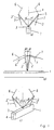
- FIG. 1 ac are shown as a schematic diagram of the possible arrangement of a tilted relative to the rocker guy support.
- the guy support 2 is preferably arranged on the upper side 3 of a jib element 1 shown symbolically here.
- This boom element 1 may be a base box or a shot of a main boom of a telescopic crane or the lattice mast element of a rigid or rockable jib.
- the drawn in the boom element 1 center axis 4 is in the ideal case, the rocker plane of the boom.
- the guy support 2 is inclined relative to the rocker plane at an angle ⁇ > 0.
- the dashed representation of the guy support 2 ' is intended to illustrate that the guy support 2 is also tilted towards the other side.
- the free end 5 of the Abspannstüzte 2 is connected to a tensioning means 6,7 preferably a side. Not shown here is the connection of the clamping means 6,7 with a boom arranged on the fixed point or a clamping device such as piston-cylinder unit or winch. A tensioning of the tensioning means 6, 7 can also be achieved without a tensioning device. On the one hand in such a way that the clamping means are arranged at a smaller or larger angle ⁇ .7 6 and then the guy support 2 is further inclined. Alternatively, it is also possible to form the guy support 2 telescopically and to achieve a degree of tension by changing the length.
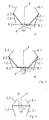
- FIG. 2 is also a schematic diagram showing the arrangement of two guy supports 2.1, 2.2.
- the peculiarity of this arrangement is that both guy supports 2.1,2.2 are arranged with only a single foot 8 on the upper side 3 of the boom element 1.
- the respective inclination angle ⁇ 1, ⁇ 2 may be the same or different.
- FIG. 3 In partial pictures ad of FIG. 3 are also shown as a schematic diagram of the possibility of the arrangement of two guy supports 2.1,2.2, which have a separate foot 8.1.8.2.
- the foot ends 8.1,8.2 are in the region of the upper side 3 of the jib element 1, while in the partial image b, the foot ends 8.1,8.2 are in the transition region from the upper side 3 to the respective side wall 9,9 '.
- part c the possibility is shown to arrange at least one foot 8.1 outside the boom element 1.
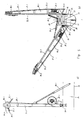
- a piston-cylinder unit 28.1,28.2 is ever provided, which is arranged at one end to the side wall 25 and the other end in the half range of the respective guy support 18.1.
- the tensioning means one rope 29.1 each is attached to one end of a rope thimble 31.1 on the head region of the guy support 18.1. From there it runs to the deflection point arranged in the direction of the boom head (also not shown here) and runs back over a deflection roller 30.1 arranged in the head area of the guy support 18.1 and from there to the winch 27.1.
- a guy clip 32.1 is arranged, which represents the rear-side securing for the respective guy support 18.1.
Landscapes
- Engineering & Computer Science (AREA)
- Mechanical Engineering (AREA)
- Jib Cranes (AREA)
Abstract
Description
Die Erfindung betrifft einen Teleskopkran, der aus einem Unterwagen, einem drehbar darauf angeordneten Oberwagen, einem Gegengewicht und einem Ausleger besteht, der wiederum einen Hauptausleger mit einem Grundkasten und mindestens einen darin ein- und ausschiebbaren Teleskopschuss aufweist.The invention relates to a telescopic crane, which consists of an undercarriage, a superstructure rotatably mounted thereon, a counterweight and a boom, which in turn has a main boom with a base box and at least one retractable and telescoping telescopic section.
Teleskopkrane der zuvor genannte Art sind bekannt. So zeigt die
Ein ähnlicher Fahrzeugkran mit Teleskopausleger ist in der
Die
Teleskopkrane der zuvor erläuterten Bauart sind im ausgefahrenen Zustand je nach Anstellwinkel unterschiedlich großen Belastungen ausgesetzt. Bei flachen und mittleren Anstellwinkeln sind die in der Einspannung der ausgefahrenen Teleskopschüsse auftretenden Belastungen ein wesentliches Kriterium für die maximale Traglast. Für einen solchen Belastungsfall ist als Momentenentlastung ein sogenannter Superliftbetrieb entwickelt worden. So ist aus der
Der guten Ordnung halber ist hierzu anzumerken, dass die Wippebene diejenige Ebene ist, in der sich der Ausleger bewegt, wenn er um seine horizontale Schwenkachse verschwenkt wird. Die Wippebene steht also senkrecht zur Wippachse des Auslegers.For the sake of good order, it should be noted that the rocker plane is the plane in which the boom moves when it is pivoted about its horizontal pivot axis. The rocker plane is therefore perpendicular to the rocker axis of the boom.
Ein realisierter Teleskopkran mit einem "Superlift" ist beispielsweise aus dem Firmenprospekt: Mannesmann Demag Fördertechnik; Demag AC 1600; 04/96, Seiten 5, 17 und 27 oder auch aus
Eine dem Superliftbetrieb ähnliche Ausgestaltung ist in der
Abschließend ist noch anzumerken, dass aus der
Eine der
Ein Ausleger mit horizontaler Seilabspannung ist aus der
Ein Ausleger eines Kranes für Containerbetrieb ist aus der
Es hat sich nun gezeigt, dass Teleskopkrane der zuvor erläuterten Art in Steilstellung auch unter Einsatz der zuvor erläuterten Superlift-Technologie nur eine begrenzte Traglast aufnehmen können.It has now been shown that telescopic cranes of the type described above in steep position even with the use of the aforementioned Superlift technology can only record a limited load.
Das der Erfindung zugrunde liegende technische Problem besteht darin, einen Teleskopkran bereitzustellen, der gerade auch in Steilstellungen des Auslegers eine erhöhte Traglast bei geringerer seitlicher Verformung aufnehmen kann.The technical problem underlying the invention is to provide a telescopic crane, which can accommodate even in steep positions of the boom an increased load with less lateral deformation.
Dieses technische Problem wird gelöst durch einen Teleskopkran mit Unterwagen, drehbar darauf angeordnetem Oberwagen, Gegengewicht und einem Ausleger, der einen Hauptausleger mit einem Grundkasten und mindestens einem darin ein- und ausschiebbaren Teleskopschuss aufweist, wobei mindestens eine am Ausleger angeordnete Abspannstütze vorhanden ist, die mit einem im Wesentlichen in Längsrichtung des Auslegers verlaufenden Spannmittel verbunden ist und deren Neigung zur Wippebene veränderbar ist.This technical problem is solved by a telescopic crane with undercarriage, rotatably mounted thereon superstructure, counterweight and a boom having a main boom with a base box and at least one retractable and telescoping telescopic section, at least one arranged on the boom guy support is present with is connected to a running substantially in the longitudinal direction of the boom clamping means and their inclination is tiltable to the rocker plane.
Es wird, insbesondere individuell angepasst an die jeweilige Wippstellung des Auslegers, eine Erhöhung der Traglast erzielt, insbesondere in einer Steilstellung, weil, wie sich gezeigt hat, in diesem Fall oftmals die seitliche Verformung des Auslegers das traglastbegrenzende Kriterium ist, nun aber durch die in der Neigung zur Wippebene veränderbare Abspannstütze auch gezielt seitliche Kräfte, die auf den Ausleger wirken, aufgenommen werden können. Insbesondere kann eine derartige Ausbildung auch eine Doppelfunktion haben, nämlich dahingehend, dass in einer Betriebsstellung ein normaler Superliftbetrieb und in einer anderen Betriebsstellung eine Kombination aus Superlift und seitlicher Abspannung durchführbar ist. Bei normalem Superliftbetrieb befindet sich die erfindungsgemäße neue Abspannstütze in der Wippebene bzw. verläuft parallel hierzu. Bei der Kombination aus Superlift und seitlicher Abspannung nimmt die Abspannstütze eine Winkelstellung zur Wippebene ein.It is, in particular individually adapted to the respective rocker position of the boom, an increase in the load achieved, especially in a steep position, because, as has been shown, in this case often the lateral deformation of the boom is the load-limiting criterion, but now by the in The inclination to the seesaw level changeable guy support also targeted lateral forces acting on the boom, can be recorded. In particular, such a design can also have a dual function, namely to the effect that in one operating position, a normal Superliftbetrieb and in another operating position, a combination of superlift and lateral bracing is feasible. In normal Superliftbetrieb the new guy support according to the invention is in the rocker plane or parallel thereto. With the combination of superlift and lateral bracing, the bracing support assumes an angular position relative to the teetering plane.
Bei einer beispielhaften Ausführungsform ist die Neigung der Abspannstütze in einer Ebene quer und/oder längs zur Längsrichtung des Auslegers veränderbar. Mit anderen Worten, die Abspannstütze ist gegenüber der Wippebene in verschieden senkrecht dazu stehenden Ebenen liegend neigbar.In an exemplary embodiment, the inclination of the guy support in a plane transversely and / or longitudinally to the longitudinal direction of the boom is variable. In other words, the The bracing support can be tilted relative to the rocker plane in planes that are perpendicular to it.
Die Veränderung der Neigung der Wippebene kann stufenweise oder kontinuierlich über ein Verschwenken der mindestens einen Abspannstütze einstellbar sein. Eine einfache Ausführungsform sieht vor, dass nur mehrere verschiedene Stufen von Neigungen zur Wippebene einnehmbar sind. Eine andere Ausführungsform kann vorsehen, dass die Neigung im Bereich von größer 0° bis 90° gegenüber der Wippebene einstellbar ist, was eine genauere Anpassung an die jeweilige Steilstellung des Auslegers und die abzusehenden Belastungen zulässt.The change in the inclination of the rocker plane can be adjustable stepwise or continuously by pivoting the at least one guy support. A simple embodiment provides that only a plurality of different stages of inclinations to the rocker plane are ingestible. Another embodiment may provide that the inclination in the range of greater than 0 ° to 90 ° relative to the rocker plane is adjustable, which allows a more accurate adaptation to the respective up position of the boom and the loads to be considered.
Beispielsweise ist am Ausleger mindestens eine gegenüber der Wippebene geneigte Abspannstütze angeordnet, die mit einem im Wesentlichen in Längsrichtung des Auslegers verlaufenden Spannmittel verbunden ist, wobei die Neigung der Abspannstütze so gewählt ist, dass die auf den Ausleger wirkende seitliche Belastung teilweise oder vollständig durch die Abspannung aufgenommen wird. Die Neigung der Abspannstütze kann quer zur Längsrichtung oder in Längsrichtung oder überlagernd quer zur und in Längsrichtung des Auslegers erfolgen.For example, on the boom at least one inclined relative to the seesaw leveling support is arranged, which is connected to a running substantially in the longitudinal direction of the boom clamping means, wherein the inclination of the guy support is chosen so that the lateral load acting on the boom partially or completely by the bracing is recorded. The inclination of the guy support can be transverse to the longitudinal direction or in the longitudinal direction or superimposed transversely to and in the longitudinal direction of the boom.
Vorzugsweise sind auf der Oberseite des jeweiligen Auslegerelementes zwei geneigte Abspannstützen vorgesehen, wobei im Regelfall die Winkelneigung beider Abspannstützen gleich ist. Sie kann aber je nach Richtung der am Ausleger angreifenden Kräfte auch verschieden sein. Die Fußenden beider Abspannstützen können an einer gemeinsamen Stelle mit der Oberseite des Auslegers verbunden sein, aber ebenso auch versetzt zueinander. Nach einem weiteren Merkmal der Erfindung ist das Fußende wenigstens einer Abspannstütze im Übergangsbereich zwischen Oberseite oder jeweiliger Seitenwand mit dem Ausleger verbunden. Alternativ gibt es auch die Möglichkeit, das Fußende wenigstens einer Abspannstütze auf einen quer zur Längsachse des Auslegers und über diesen hinauskragenden Träger anzuordnen.Preferably, two inclined guy supports are provided on the upper side of the respective boom element, wherein as a rule the angle inclination of both guy supports is the same. But it can also be different depending on the direction of the forces acting on the boom. The foot ends of both guy supports can be connected at a common location to the top of the boom, but also offset from one another. According to a further feature of the invention, the foot end of at least one guy support is connected to the boom in the transition region between the upper side or the respective side wall. Alternatively, it is also possible to arrange the foot end of at least one guy support on a transverse to the longitudinal axis of the boom and beyond this projecting carrier.
Die beispielhafte Anordnung hat den Vorteil, dass je nach Winkelstellung der Abspannstützen der Anteil der Abspannkraft, der in die Seitenrichtung wirksam wird, stufenlos oder kontinuierlich verändert werden kann. Im Falle der Anordnung von zwei versetzt angeordneten Abspannstützen bedeutet dies, dass in der einen Extremlage, d. h. in der Vertikalsteflung, die beiden parallel stehenden Abspannstützen die gleiche Wirkung im Sinne eines Superliftbetriebes haben wie der bekannte Abspannbock. In einer Winkelstellung <90° bis >0° für die beiden Abspannstützen wird die wirksame Spannkraft aufgeteilt in eine Komponente Superliftbetrieb und eine Komponente seitliche Abspannung. In der zweiten Extremlage, d. h. in der Horizontalstellung, bewirken die beiden Abspannstützen nur eine Verstärkung in beide Seitenrichtungen.The exemplary arrangement has the advantage that, depending on the angular position of the guy supports, the proportion of the guy force acting in the lateral direction can be changed continuously or continuously. In the case of the arrangement of two staggered anchoring supports, this means that in one extreme position, ie in the vertical staging, the two parallel anchoring supports have the same effect in the sense of a superlift operation as the known guy truss. In an angular position <90 ° to> 0 ° for the two guy supports, the effective clamping force is divided into a component Superliftbetrieb and a component lateral bracing. In the second extreme position, ie in the horizontal position, cause the two guy supports only a gain in both lateral directions.
Das jeweilig freie Kopfende der Abspannstütze ist über ein erstes Spannmittel wahlweise mit dem Unterwagen, dem Oberwagen, dem Fußbereich des Auslegers, dem festen oder separat geführten Gegengewicht oder dem Boden in Richtung Fußende des Auslegers und über ein weiteres Spannmittel mit einer ausgewählten Stelle des Auslegers in Richtung Auslegerkopf verbunden. Die jeweils gewünschte Winkelstellung der Abspannstützen kann stufenweise oder kontinuierlich über ein Verschwenken der Abspannstützen eingestellt werden. Damit ist auch eine asymmetrische Winkeleinstellung möglich. Dies bedeutet, dass bei einer angreifenden Seitenkraft nur an einer Seite die jeweilige Abspannstützen mehr in Richtung seitlicher Abspannung geneigt wird, während die zweite Abspannstütze in einer Mittellage verbleibt.The respective free head end of the guy support is via a first clamping means optionally with the undercarriage, the uppercarriage, the foot area of the boom, the fixed or separately guided counterweight or the ground in the direction of the foot end of the boom and another clamping means with a selected location of the boom in Connected to the boom head. The respective desired angular position of the guy supports can be adjusted stepwise or continuously by pivoting the guy supports. This also allows an asymmetrical angle adjustment. This means that at an attacking lateral force only on one side of the respective guy supports is inclined more in the direction of lateral bracing, while the second guy support remains in a central position.
Da auch der Abstand der Spannmittel vom Ausleger Einfluss auf die gewünschte Verstärkung hat, ist vorgesehen, die Länge der Abspannstützen in Stufen oder kontinuierlich zu verändern. Die Spannmittel können als Seil oder als Stange ausgebildet sein. Das Spannmittel bzw. die Spannmittel können mit und ohne Vorspannung angeordnet werden. Im Falle einer Vorspannung und eines nachregulierbaren Spanngrades wirkt das Spannmittel mit einer Spannvorrichtung zusammen. Vorzugsweise ist dies eine Winde oder eine Kolben-Zylinder-Einheit. Aber auch die Winkelverstellung und/oder die Längenänderung der Abspannstütze kann im Sinne einer Spannvorrichtung genutzt werden. Die Spannvorrichtungen sind wahlweise an den Abspannstützen, am Ausleger, am Ober- oder Unterwagen oder am Gegengewicht anordenbar.Since the distance of the clamping means from the boom has influence on the desired gain, it is intended to change the length of the guy supports in stages or continuously. The clamping means may be formed as a rope or as a rod. The clamping means or the clamping means can be arranged with and without bias. In the case of a bias voltage and a re-adjustable degree of tension, the clamping means cooperates with a tensioning device. Preferably, this is a winch or a piston-cylinder unit. But also the angle adjustment and / or the change in length of the guy support can be used in the sense of a clamping device. The clamping devices can be arranged optionally on the guy supports, on the boom, on the upper or undercarriage or on the counterweight.
Vorzugsweise werden die Abspannstützen am Hauptausleger im Bereich des Grundkastens angeordnet, insbesondere im vorderen Bereich zwischen der Anlenkung des Wippzylinders und der vorderem Lagerung. Zur kontinuierlichen Verstellung der Abspannstützen ist vorzugsweise jede Abspannstütze mit einer auf dem Grundkasten sich abstützenden Kolben-Zylinder-Einheit verbunden. Zur Anordnung der Winde weist nach einem weiteren Merkmal der Erfindung die Abspannstütze zwei Holme auf, zwischen denen die Winde anordenbar ist.Preferably, the guy supports are arranged on the main boom in the region of the basic box, in particular in the front region between the articulation of the luffing cylinder and the front storage. For continuous adjustment of the guy supports, each guy support is preferably connected to a piston-cylinder unit supported on the base box. For the arrangement of the winch, according to a further feature of the invention, the guy support two spars, between which the winch can be arranged.
Die Ausrüstung des Teleskopauslegers kann noch ergänzt werden mit der Anordnung eines aus Gittermastteilen gebildeten starren oder wippbaren Hilfsauslegers. Auch an diese Auslegerelemente kann die vorgeschlagene seitliche Abspannung angebracht werden.The equipment of the telescopic boom can be supplemented with the arrangement of a rigid or rocking jib formed of lattice mast parts. Also to these boom elements, the proposed lateral bracing can be attached.
Besonders wirkungsvoll kann die seitliche Abspannung eingesetzt werden, wenn der Kran mit einem Messmittel zur Erfassung der seitlichen Verformung des Auslegers versehen ist. Überschreitet die Verformung einen festgelegten zulässigen Wert, wird das mit der Abspannung verbundene Spannmittel aktiviert und die Abspannung nachgespannt. Der Grad der seitlichen Verformung kann direkt oder indirekt Ober Krangrößen ermittelt werden. Beispielsweise sind dies die Seilspannung, die Seillänge und Seildehnung. Aber auch über die an den Ausleger angreifenden Kräfte in Form des seitlich auftretenden Windes, der Sonneneinstrahlung sowie der im Ausleger vorherrschenden Temperaturen kann eine Aussage über den Grad der seitliche Verformung gemacht werden.The lateral bracing can be used particularly effectively if the crane is provided with a measuring device for detecting the lateral deformation of the boom. If the deformation exceeds a specified permissible value, the clamping device connected to the bracing is activated and the bracing is tensioned. The degree of lateral deformation can be determined directly or indirectly above crane sizes. For example, these are the rope tension, the rope length and rope elongation. But also on the forces acting on the boom in the form of the laterally occurring wind, solar radiation and the prevailing temperatures in the boom, a statement about the degree of lateral deformation can be made.
Im Folgenden sind zur weiteren Erläuterung und zum besseren Verständnis mehrere Ausführungsbeispiele der Erfindung unter Bezugnahme auf die beigefügten Zeichnungen näher beschrieben. Es zeigt:
- Fig.1a-1c
- als Prinzipskizze die mögliche Anordnung einer gegenüber der Wippebene geneigten Abspannstütze
Figur 2- als Prinzipskizze die Anordnung zweier geneigter Abspannstützen mit einem gemeinsamen Fußende.
- Figur3a-3d
- als Prinzipskizze die mögliche Anordnung zweier geneigter Abspannstützen mit getrennten Fußenden
Figur 4- als Prinzipskizze die Anordnung einer quer liegenden Abspannstütze
- Figur 5a
- in einer Vorderansicht ein praktisches Ausführungsbeispiel mit zwei neigbaren Abspannstütze.
- Figur 5b
- eine Seitenansicht von
Figur 5a .
- 1a-1c
- as a schematic diagram of the possible arrangement of a tilted relative to the rocker guy support
- FIG. 2
- as a schematic diagram of the arrangement of two inclined guy supports with a common foot.
- Figur3a 3d
- as a schematic diagram of the possible arrangement of two inclined guy supports with separate foot ends
- FIG. 4
- as a schematic diagram of the arrangement of a transverse guy support
- FIG. 5a
- in a front view of a practical embodiment with two tilting guy support.
- FIG. 5b
- a side view of
FIG. 5a ,
In den
Im Teilbild b ist die Möglichkeit dargestellt die Abspannstütze 2 auch in der anderen Ebene in einem Winkel β>0 zu neigen. Teilbild c zeigt die Möglichkeit, die Abspannstütze 2 überlappend in beiden Ebenen zu neigen.In the partial image b, the possibility is shown of tilting the bracing
In
In Teilbildern a-d von
Im Teilbild c ist die Möglichkeit dargestellt zumindestens ein Fußende 8.1 außerhalb des Auslegerelementes 1 anzuordnen. Als Rüsthilfe ist je eine Kolben-Zylinder-Einheit 28.1,28.2 vorgesehen, die an einem Ende an der Seitenwand 25 und mit dem anderen Ende im hälftigen Bereich der jeweiligen Abspannstütze 18.1 angeordnet ist.In part c, the possibility is shown to arrange at least one foot 8.1 outside the
Das Spannmittel, je ein Seil 29.1 ist mit einem Ende Ober eine Seilkausche 31.1 am Kopfbereich der Abspannstütze 18.1 befestigt. Von dort läuft es zum in Richtung Auslegerkopf angeordneten Umlenkpunkt (auch hier nicht dargestellt) und läuft zurück über ein im Kopfbereich der Abspannstütze 18.1 angeordneten Umlenkrolle 30.1 und von dort zur Winde 27.1.The tensioning means, one rope 29.1 each is attached to one end of a rope thimble 31.1 on the head region of the guy support 18.1. From there it runs to the deflection point arranged in the direction of the boom head (also not shown here) and runs back over a deflection roller 30.1 arranged in the head area of the guy support 18.1 and from there to the winch 27.1.
Auf der rückwärtigen Seite im Kopfbereich der Abspannstütze 18.1 ist eine Abspannspange 32.1 angeordnet, die die rückseitige Sicherung für die jeweilige Abspannstütze 18.1 darstellt.On the rear side in the head area of the guy support 18.1, a guy clip 32.1 is arranged, which represents the rear-side securing for the respective guy support 18.1.
Claims (32)
- A telescopic crane, comprising:- a substructure,- a superstructure rotatably mounted on the substructure,- a counterweight,- a boom structure (1) including a main boom having a boom base (13) and at least one telescope section which is received in the boom base and displaceable between retracted and extended positions, and- at least one a guy support (2; 21., 2.2; 18.1, 18.2) arranged at the boom structure (1) and connected with a tension means (6, 7; 29.1, 29.2; 32.1, 32.2) extending substantially in a longitudinal direction of the boom structure (1), wherein the inclination (α, β) of the guy support with respect to a luffing plane (4) is variable.
- The telescopic crane of claim 1,
characterized in that the inclination (α, β) of the guy support (2; 21., 2.2; 18.1, 18.2) is variable in a plane extending transversely to and/or along the longitudinal direction of the boom structure (1). - The telescopic crane of claim 1 or 2,
characterized in that the inclination (α, β) of the guy support (2; 21., 2.2; 18.1, 18.2) is adjustable step-by-step or continuously in a plane extending transversely to and/or along the longitudinal direction of the boom structure (1). - The telescopic crane of one of the preceding claims,
characterized in that an foot (8.1) of at least one guy support (2.1) is arranged on a support (10), wherein the support is arranged transversely to the longitudinal direction of the boom structure (1) and extends beyond the boom structure. - The telescopic crane of one of the preceding claims,
characterized in that a free top (10) of a guy support (2; 21., 2.2; 18.1, 18.2) is connected via a first tension means (7, 32.1, 32.2) alternatively to the superstructure, the substructure, a base area of the boom structure (1), the counter weight, which is fixedly arranged or which is separately guided, or the ground in the direction of the foot of the boom structure (1), and is connected via a further tension means (6; 29.1, 29.2) to a selected position of the main boom (1) or a component of a boom structure extension in a direction to the top of the boom structure (1). - The telescopic crane of claim 5,
characterized in that the free head of the at least one guy support (18.1,18.2) is connected to the head or the collar of one of the inner telescopic sections via a tension means (6; 29.1, 29.2). - The telescopic crane of claim 5,
characterized in that the free head of the at least one guy support (18.1,18.2) is connected to a part of an auxiliary lattice boom via a tension means (6; 29.1, 29.2), wherein the auxiliary lattice boom is one of fixed or teetering. - The telescopic crane of one of the preceding claims,
characterized in that the length of the guy support (2; 21., 2.2; 18.1, 18.2) is variable. - The telescopic crane of claim 9,
characterized in that the length of the guy support (2; 21., 2.2; 18.1, 18.2) is variable step-by-step. - The telescopic crane of claim 8,
characterized in that the length of the guy support (2; 2.1, 2.2; 18.1, 18.2) is variable continuously. - The telescopic crane of one of the preceding claims,
characterized in that the tension means (6, 7) is a rope (29.1; 29.2) and/or a rod (32.1, 32.2). - The telescopic crane of one of the preceding claims,
characterized in that the tension means (6, 7; 29.1, 29.2; 32.1, 32.2) interacts with a tension device (27.1; 27.2). - The telescopic crane of one of the preceding claims,
characterized in that tension devices (27.1, 27.2) for the tension means (6, 7; 29.1, 29.2; 32.1, 32.2) of each guy support (2; 2.1, 2.2; 18.1, 18.2) are provided, wherein the tension devices are separately controllable. - The telescopic crane of claim 12 or 13,
characterized in that the at least one tension device (27.1, 27.2) is arranged on at least one of the guy support (18.1, 18.2), the superstructure, the substructure, the main boom (1), the counter weight and an boom extension. - The telescopic crane of claim 12, 13 or 14,
characterized in that the tension device is one of a winch (27.1, 27.2) and a piston and cylinder unit. - The telescopic crane of one of the preceding claims,
characterized in that a variation of the inclination of the guy support (2; 2.1, 2.2; 18.1, 18.2) is usable to tense the accompanying tension means (6, 7; 29.1, 29.2; 32.1, 32.2). - The telescopic crane of one of the preceding claims,
characterized in that a variation of the length of the guy support (2; 2.1, 2.2; 18.1, 18.2) is usable to tension the accompanying tension means (6, 7; 29.1, 29.2; 32.1, 32.2). - The telescopic crane of one of the preceding claims,
characterized in that the at least one guy support (2) is arranged on the top side (3) of the boom structure (1). - The telescopic crane of one of the preceding claims,
characterized in that one pair (3) of guy supports (2.1, 2.2; 18.1, 18.2) is arranged on the boom structure (1), wherein one guy support (2.1; 18.1) of a pair of guy supports can be inclined to one side of the boom structure (1) and the other guy support (2.2; 18.2) can be inclined to another side of the boom structure (1). - The telescopic crane of claim 19,
characterized in that the pair of guy supports (2.1, 2.2; 18.1, 18.2) is arranged at a predetermined position at a top side (3) of the boom structure (1). - The telescopic crane of claim 19 or 20,
characterized in that one pair of guy supports (18.1, 18.2) is arranged on the main boom in an area of the boom base (134). - The telescopic crane of claim 21,
characterized in that the pair of guy supports (18.1, 18.2) is arranged in a forward region between a luffing cylinder and a forward bearing on the boom base (13). - The telescopic crane of one of the claims 19-22,
characterized in that the foots (8.1, 8.2) of both guy supports (2.1, 2.2; 18.1, 18.2) are connected to a top side (3) of the boom structure (3) in the same position. - The telescopic crane of one of the claims 19-22,
characterized in that the foots (8.1, 8.2) of both guy supports (2.1, 2.2) are connected to a top side (3) of the boom structure (1) in a manner spatially displaced to each other. - The telescopic crane of one of the preceding claims,
characterized in that a foot end (8.1, 8.2) of at least one guy support (2.1, 2.2; 18.1, 18.2) is connected to the boom structure (1) in a transition area between the top side (3) and a respective side wall (9, 9') of the boom base (13). - The telescopic crane of one of the preceding claims,
characterized in that comprising a piston and cylinder unit, supported by the boom base, wherein the at least one pair of guy supports is operatively connected with the piston and cylinder unit for implementing a lateral inclination of the at least one pair of guy supports. - The telescopic crane of one of the preceding claims,
characterized in that the at least one guy support (18.1; 18.2) comprises two substantial parallel poles (21.1; 22.1; 21.2; 21.2). - The telescopic crane of claim 27,
characterized in that a winch (27.1; 27.2) to tension the tension means (6, 7; 29.1, 29.2; 32.1, 32.2) is positioned between the poles (21.1; 22.1; 21.2; 21.2) of the respective guy supports (18.1; 18.2). - The telescopic crane of one of the preceding claims,
characterized in that a rigid fly jib made in the form of a lattice tower is mounted to the head of the innermost telescope section. - The telescopic crane of one of the claims 1-28,
characterized in that a luffing fly jib made in the form of a lattice tower is mounted to the head of an innermost telescope section with the aid of at least one slewed support. - The telescopic crane of one of the claims 1-30,
characterized in that a measuring means for determining a lateral deformation of the boom structure is provided, wherein the measuring means is operatively linked to a tensioning device by which the tautening degree of the lateral guying is influenced. - The telescopic crane of claim 31,
characterized in that the lateral deformation is determined, directly or indirectly, via crane parameters including for example rope tension, rope length, rope extension, forces acting on the boom structure, exposure to side winds, exposure to sunlight and temperatures of the main boom.
Priority Applications (3)
| Application Number | Priority Date | Filing Date | Title |
|---|---|---|---|
| EP03014531A EP1354842B1 (en) | 1999-06-28 | 2000-06-26 | Telescopic crane |
| DE20018742U DE20018742U1 (en) | 1999-06-28 | 2000-06-26 | Telescopic crane |
| DE20023223U DE20023223U1 (en) | 1999-06-28 | 2000-06-26 | telescopic crane |
Applications Claiming Priority (4)
| Application Number | Priority Date | Filing Date | Title |
|---|---|---|---|
| DE19930537 | 1999-06-28 | ||
| DE19930537 | 1999-06-28 | ||
| DE10022658A DE10022658B4 (en) | 1999-06-28 | 2000-04-28 | telescopic crane |
| DE10022658 | 2000-04-28 |
Related Child Applications (1)
| Application Number | Title | Priority Date | Filing Date |
|---|---|---|---|
| EP03014531A Division EP1354842B1 (en) | 1999-06-28 | 2000-06-26 | Telescopic crane |
Publications (4)
| Publication Number | Publication Date |
|---|---|
| EP1065166A2 EP1065166A2 (en) | 2001-01-03 |
| EP1065166A3 EP1065166A3 (en) | 2002-05-08 |
| EP1065166B1 EP1065166B1 (en) | 2003-08-13 |
| EP1065166B2 true EP1065166B2 (en) | 2009-02-18 |
Family
ID=26005614
Family Applications (1)
| Application Number | Title | Priority Date | Filing Date |
|---|---|---|---|
| EP00250210A Expired - Lifetime EP1065166B2 (en) | 1999-06-28 | 2000-06-26 | Telescopic crane |
Country Status (5)
| Country | Link |
|---|---|
| EP (1) | EP1065166B2 (en) |
| JP (1) | JP5013630B2 (en) |
| AT (2) | ATE285980T1 (en) |
| DE (2) | DE20022790U1 (en) |
| ES (2) | ES2204452T3 (en) |
Cited By (1)
| Publication number | Priority date | Publication date | Assignee | Title |
|---|---|---|---|---|
| DE102020215260A1 (en) | 2020-12-03 | 2022-06-09 | Tadano Faun Gmbh | Method of operating a crane and crane |
Families Citing this family (16)
| Publication number | Priority date | Publication date | Assignee | Title |
|---|---|---|---|---|
| DE20020974U1 (en) * | 2000-12-12 | 2002-04-25 | Liebherr-Werk Ehingen Gmbh, 89584 Ehingen | mobile crane |
| DE10128986A1 (en) | 2001-06-11 | 2002-12-19 | Demag Mobile Cranes Gmbh | Mobile crane has load increasing device permanently connected to main jib part and with individual weight of telescopic extensions each reduced to avoid exceeding maximum permissible weight without having to reduce number of extensions |
| DE20218971U1 (en) * | 2002-12-06 | 2004-04-08 | Liebherr-Werk Ehingen Gmbh | Mobile crane with long arms |
| DE10315989B4 (en) * | 2003-04-08 | 2007-10-25 | Grove U.S. Llc | Clamping system for a mobile telescopic crane |
| JP2005162392A (en) * | 2003-12-02 | 2005-06-23 | Tadano Ltd | Mobile crane |
| DE202005015044U1 (en) | 2004-03-26 | 2005-12-22 | Terex-Demag Gmbh & Co. Kg | A vehicle crane system comprising a vehicle crane and an assembly aid for assembling a guying device |
| JP2006206233A (en) * | 2005-01-27 | 2006-08-10 | Tadano Ltd | Telescopic boom horizontal deflection restricting device for travelling crane |
| JP2006306546A (en) * | 2005-04-27 | 2006-11-09 | Tadano Ltd | Crane device with jib |
| DE202005016743U1 (en) * | 2005-10-25 | 2007-03-29 | Liebherr-Werk Ehingen Gmbh | Crane comprises a bracing device having two brace supports hinged on an auxiliary boom and inclined opposite a rocker surface |
| AT10273U1 (en) * | 2007-05-03 | 2008-12-15 | Palfinger Ag | ADJUSTMENT MECHANISM FOR A WINCH |
| DE202008006167U1 (en) | 2008-05-06 | 2008-07-17 | Terex-Demag Gmbh | Laterally strained lattice mast |
| JP5271122B2 (en) * | 2009-03-11 | 2013-08-21 | 株式会社タダノ | Boom and jib lateral deflection suppressing device for boom working vehicle with jib |
| NL1037444C2 (en) * | 2009-11-04 | 2011-05-11 | Bastiaan Jong | CRANE. |
| JP5629160B2 (en) * | 2010-08-18 | 2014-11-19 | 株式会社タダノ | Mobile crane |
| JP5635331B2 (en) * | 2010-08-18 | 2014-12-03 | 株式会社タダノ | Mobile crane |
| JP5649870B2 (en) * | 2010-08-20 | 2015-01-07 | 株式会社タダノ | Mobile crane |
Citations (6)
| Publication number | Priority date | Publication date | Assignee | Title |
|---|---|---|---|---|
| DE1751383U (en) † | 1957-06-04 | 1957-08-29 | Horst Vesper | CRANE JIB IN SHELL CONSTRUCTION. |
| DE3030820C2 (en) † | 1979-08-17 | 1987-01-29 | Coles Cranes Ltd., Sunderland, Tyne and Wear | Mobile crane with a telescopic boom |
| DE3840408C2 (en) † | 1988-03-23 | 1990-11-29 | Liebherr-Werk Ehingen Gmbh, 7930 Ehingen, De | |
| DE19606109A1 (en) † | 1995-12-12 | 1997-06-19 | Liebherr Werk Ehingen | Mobile crane |
| DE29720972U1 (en) † | 1997-11-26 | 1999-03-25 | Ec Engineering + Consulting Spezialmaschinen Gmbh, 89079 Ulm | Telescopic boom |
| DE19802187A1 (en) † | 1998-01-16 | 1999-07-22 | Mannesmann Ag | Device for bracing of superlift unit of telescopic crane, especially mobile crane |
Family Cites Families (5)
| Publication number | Priority date | Publication date | Assignee | Title |
|---|---|---|---|---|
| JPS4737785Y1 (en) * | 1969-02-28 | 1972-11-15 | ||
| DE3113763A1 (en) * | 1981-04-04 | 1982-10-28 | Mannesmann AG, 4000 Düsseldorf | Vehicle crane with telescopic jib |
| JPS59164284A (en) * | 1983-03-07 | 1984-09-17 | Nissan Motor Co Ltd | Rig-structure of sailing vessel |
| JPH0450304Y2 (en) * | 1987-09-02 | 1992-11-26 | ||
| DE4337415C2 (en) * | 1993-10-27 | 1996-09-26 | Mannesmann Ag | Crane, especially a large mobile crane |
-
2000
- 2000-04-28 DE DE20022790U patent/DE20022790U1/en not_active Expired - Lifetime
- 2000-04-28 DE DE20023565U patent/DE20023565U1/en not_active Expired - Lifetime
- 2000-06-26 EP EP00250210A patent/EP1065166B2/en not_active Expired - Lifetime
- 2000-06-26 AT AT03014531T patent/ATE285980T1/en not_active IP Right Cessation
- 2000-06-26 AT AT00250210T patent/ATE247071T1/en not_active IP Right Cessation
- 2000-06-26 ES ES00250210T patent/ES2204452T3/en not_active Expired - Lifetime
- 2000-06-26 ES ES03014531T patent/ES2235131T3/en not_active Expired - Lifetime
- 2000-06-28 JP JP2000194127A patent/JP5013630B2/en not_active Expired - Lifetime
Patent Citations (6)
| Publication number | Priority date | Publication date | Assignee | Title |
|---|---|---|---|---|
| DE1751383U (en) † | 1957-06-04 | 1957-08-29 | Horst Vesper | CRANE JIB IN SHELL CONSTRUCTION. |
| DE3030820C2 (en) † | 1979-08-17 | 1987-01-29 | Coles Cranes Ltd., Sunderland, Tyne and Wear | Mobile crane with a telescopic boom |
| DE3840408C2 (en) † | 1988-03-23 | 1990-11-29 | Liebherr-Werk Ehingen Gmbh, 7930 Ehingen, De | |
| DE19606109A1 (en) † | 1995-12-12 | 1997-06-19 | Liebherr Werk Ehingen | Mobile crane |
| DE29720972U1 (en) † | 1997-11-26 | 1999-03-25 | Ec Engineering + Consulting Spezialmaschinen Gmbh, 89079 Ulm | Telescopic boom |
| DE19802187A1 (en) † | 1998-01-16 | 1999-07-22 | Mannesmann Ag | Device for bracing of superlift unit of telescopic crane, especially mobile crane |
Cited By (3)
| Publication number | Priority date | Publication date | Assignee | Title |
|---|---|---|---|---|
| DE102020215260A1 (en) | 2020-12-03 | 2022-06-09 | Tadano Faun Gmbh | Method of operating a crane and crane |
| DE102020215260B4 (en) | 2020-12-03 | 2022-06-23 | Tadano Faun Gmbh | Method of operating a crane and crane |
| US11708249B2 (en) | 2020-12-03 | 2023-07-25 | Tadano Faun Gmbh | Method for operating a crane, and crane |
Also Published As
| Publication number | Publication date |
|---|---|
| EP1065166A2 (en) | 2001-01-03 |
| EP1065166A3 (en) | 2002-05-08 |
| EP1065166B1 (en) | 2003-08-13 |
| ES2235131T3 (en) | 2005-07-01 |
| ATE247071T1 (en) | 2003-08-15 |
| JP5013630B2 (en) | 2012-08-29 |
| DE20022790U1 (en) | 2002-07-04 |
| DE20023565U1 (en) | 2004-11-25 |
| ATE285980T1 (en) | 2005-01-15 |
| ES2204452T3 (en) | 2004-05-01 |
| JP2001058791A (en) | 2001-03-06 |
Similar Documents
| Publication | Publication Date | Title |
|---|---|---|
| DE10022600B4 (en) | telescopic crane | |
| EP1065166B2 (en) | Telescopic crane | |
| EP1900675B1 (en) | Crane truck | |
| EP1135322B1 (en) | Crane, especially a self-propelled crane | |
| DE20020974U1 (en) | mobile crane | |
| EP0354167A1 (en) | Crane, especially a crane for heavy loads | |
| DE2917829C2 (en) | ||
| EP3793930B1 (en) | Support for the rear anchoring line of a telescopic crane | |
| DE2430359A1 (en) | CHASSIS FRAME FOR A LIFT | |
| AT526869B1 (en) | Telescopic boom with fold-out mast | |
| DE20107984U1 (en) | Mobile crane with luffing jib | |
| DE202013011183U1 (en) | Telescopic super lift mast | |
| DE20023869U1 (en) | Telescopic crane incorporates a bottom carriage with a top carriage turning on it, a counter weight and a jib having a main jib with a base casing and a telescopic projection sliding in and out. | |
| DE20023369U1 (en) | Telescopic crane incorporates a bottom carriage with a top carriage turning on it, a counter weight and a jib having a main jib with a base casing and a telescopic projection sliding in and out. | |
| DE202005016743U1 (en) | Crane comprises a bracing device having two brace supports hinged on an auxiliary boom and inclined opposite a rocker surface | |
| DE20023223U1 (en) | telescopic crane | |
| DE102023119815B4 (en) | Mounting frame, mobile crane and method for mounting a guying device on a telescopic boom | |
| DE20023867U1 (en) | Telescopic crane incorporates a bottom carriage with a top carriage turning on it, a counter weight and a jib having a main jib with a base casing and a telescopic projection sliding in and out. | |
| DE2064511C3 (en) | Arrangement for erecting a mast construction | |
| DE3810070A1 (en) | HEIGHT CONVEYOR CARRIED BY A VEHICLE | |
| DE1781048C3 (en) | Multi-part telescopic mast for lift trucks | |
| DE2224453C3 (en) | Foldable tower crane | |
| DE102012025128A1 (en) | Unclamping device for spatial unclamping of unclampable boom of e.g. tracked crane for handling loads, has inner and outer segments hinged at upper structure in region of boom hinge axis, and supported against boom base piece by cylinders | |
| DE2101505A1 (en) | Jib crane | |
| DE8304328U1 (en) | Device for inspecting the underside of bridges |
Legal Events
| Date | Code | Title | Description |
|---|---|---|---|
| PUAI | Public reference made under article 153(3) epc to a published international application that has entered the european phase |
Free format text: ORIGINAL CODE: 0009012 |
|
| AK | Designated contracting states |
Kind code of ref document: A2 Designated state(s): AT BE CH CY DE DK ES FI FR GB GR IE IT LI LU MC NL PT SE |
|
| AX | Request for extension of the european patent |
Free format text: AL;LT;LV;MK;RO;SI |
|
| 17P | Request for examination filed |
Effective date: 20011030 |
|
| PUAL | Search report despatched |
Free format text: ORIGINAL CODE: 0009013 |
|
| AK | Designated contracting states |
Kind code of ref document: A3 Designated state(s): AT BE CH CY DE DK ES FI FR GB GR IE IT LI LU MC NL PT SE |
|
| AX | Request for extension of the european patent |
Free format text: AL;LT;LV;MK;RO;SI |
|
| RAP1 | Party data changed (applicant data changed or rights of an application transferred) |
Owner name: DEMAG MOBILE CRANES GMBH & CO. KG |
|
| GRAH | Despatch of communication of intention to grant a patent |
Free format text: ORIGINAL CODE: EPIDOS IGRA |
|
| AKX | Designation fees paid |
Designated state(s): AT BE CH CY DE DK ES FI FR GB GR IE IT LI LU MC NL PT SE |
|
| GRAH | Despatch of communication of intention to grant a patent |
Free format text: ORIGINAL CODE: EPIDOS IGRA |
|
| GRAH | Despatch of communication of intention to grant a patent |
Free format text: ORIGINAL CODE: EPIDOS IGRA |
|
| RAP1 | Party data changed (applicant data changed or rights of an application transferred) |
Owner name: TEREX-DEMAG GMBH & CO. KG |
|
| GRAA | (expected) grant |
Free format text: ORIGINAL CODE: 0009210 |
|
| AK | Designated contracting states |
Designated state(s): AT BE CH CY DE DK ES FI FR GB GR IE IT LI LU MC NL PT SE |
|
| PG25 | Lapsed in a contracting state [announced via postgrant information from national office to epo] |
Ref country code: FI Free format text: LAPSE BECAUSE OF FAILURE TO SUBMIT A TRANSLATION OF THE DESCRIPTION OR TO PAY THE FEE WITHIN THE PRESCRIBED TIME-LIMIT Effective date: 20030813 Ref country code: IE Free format text: LAPSE BECAUSE OF FAILURE TO SUBMIT A TRANSLATION OF THE DESCRIPTION OR TO PAY THE FEE WITHIN THE PRESCRIBED TIME-LIMIT Effective date: 20030813 Ref country code: CY Free format text: LAPSE BECAUSE OF FAILURE TO SUBMIT A TRANSLATION OF THE DESCRIPTION OR TO PAY THE FEE WITHIN THE PRESCRIBED TIME-LIMIT Effective date: 20030813 |
|
| REG | Reference to a national code |
Ref country code: GB Ref legal event code: FG4D Free format text: NOT ENGLISH |
|
| RIN1 | Information on inventor provided before grant (corrected) |
Inventor name: KUHN, ROLAND, DIPL.-ING. Inventor name: MARX, MARKUS Inventor name: ZIMMER, WALTER Inventor name: IRSCH, MICHAEL, DIPL.-ING. Inventor name: STOWASSER, WALTER, DIPL.-ING. Inventor name: FERY, JENS, DIPL.-ING. Inventor name: FRIES, OLIVER, DR.-ING. Inventor name: CONRAD, FRANK, DIPL.-ING. |
|
| REG | Reference to a national code |
Ref country code: CH Ref legal event code: EP |
|
| REG | Reference to a national code |
Ref country code: CH Ref legal event code: NV Representative=s name: DR. LUSUARDI AG |
|
| REG | Reference to a national code |
Ref country code: IE Ref legal event code: FG4D Free format text: GERMAN |
|
| REF | Corresponds to: |
Ref document number: 50003246 Country of ref document: DE Date of ref document: 20030918 Kind code of ref document: P |
|
| PG25 | Lapsed in a contracting state [announced via postgrant information from national office to epo] |
Ref country code: DK Free format text: LAPSE BECAUSE OF FAILURE TO SUBMIT A TRANSLATION OF THE DESCRIPTION OR TO PAY THE FEE WITHIN THE PRESCRIBED TIME-LIMIT Effective date: 20031113 Ref country code: GR Free format text: LAPSE BECAUSE OF FAILURE TO SUBMIT A TRANSLATION OF THE DESCRIPTION OR TO PAY THE FEE WITHIN THE PRESCRIBED TIME-LIMIT Effective date: 20031113 Ref country code: SE Free format text: LAPSE BECAUSE OF FAILURE TO SUBMIT A TRANSLATION OF THE DESCRIPTION OR TO PAY THE FEE WITHIN THE PRESCRIBED TIME-LIMIT Effective date: 20031113 |
|
| GBT | Gb: translation of ep patent filed (gb section 77(6)(a)/1977) |
Effective date: 20031209 |
|
| PG25 | Lapsed in a contracting state [announced via postgrant information from national office to epo] |
Ref country code: PT Free format text: LAPSE BECAUSE OF FAILURE TO SUBMIT A TRANSLATION OF THE DESCRIPTION OR TO PAY THE FEE WITHIN THE PRESCRIBED TIME-LIMIT Effective date: 20040113 |
|
| PLBQ | Unpublished change to opponent data |
Free format text: ORIGINAL CODE: EPIDOS OPPO |
|
| PLBI | Opposition filed |
Free format text: ORIGINAL CODE: 0009260 |
|
| PLBI | Opposition filed |
Free format text: ORIGINAL CODE: 0009260 |
|
| PLBQ | Unpublished change to opponent data |
Free format text: ORIGINAL CODE: EPIDOS OPPO |
|
| 26 | Opposition filed |
Opponent name: LIEBHERR-WERK EHINGEN GMBH Effective date: 20040122 |
|
| REG | Reference to a national code |
Ref country code: IE Ref legal event code: FD4D |
|
| 26 | Opposition filed |
Opponent name: DEUTSCHE GROVE GMBH Effective date: 20040223 Opponent name: LIEBHERR-WERK EHINGEN GMBH Effective date: 20040122 |
|
| REG | Reference to a national code |
Ref country code: ES Ref legal event code: FG2A Ref document number: 2204452 Country of ref document: ES Kind code of ref document: T3 |
|
| NLR1 | Nl: opposition has been filed with the epo |
Opponent name: LIEBHERR-WERK EHINGEN GMBH |
|
| ET | Fr: translation filed | ||
| NLR1 | Nl: opposition has been filed with the epo |
Opponent name: DEUTSCHE GROVE GMBH Opponent name: LIEBHERR-WERK EHINGEN GMBH |
|
| PLAX | Notice of opposition and request to file observation + time limit sent |
Free format text: ORIGINAL CODE: EPIDOSNOBS2 |
|
| PG25 | Lapsed in a contracting state [announced via postgrant information from national office to epo] |
Ref country code: LU Free format text: LAPSE BECAUSE OF NON-PAYMENT OF DUE FEES Effective date: 20040626 |
|
| PG25 | Lapsed in a contracting state [announced via postgrant information from national office to epo] |
Ref country code: BE Free format text: LAPSE BECAUSE OF NON-PAYMENT OF DUE FEES Effective date: 20040630 Ref country code: MC Free format text: LAPSE BECAUSE OF NON-PAYMENT OF DUE FEES Effective date: 20040630 |
|
| PLAX | Notice of opposition and request to file observation + time limit sent |
Free format text: ORIGINAL CODE: EPIDOSNOBS2 |
|
| BERE | Be: lapsed |
Owner name: *TEREX-DEMAG G.M.B.H. & CO. K.G. Effective date: 20040630 |
|
| PLAX | Notice of opposition and request to file observation + time limit sent |
Free format text: ORIGINAL CODE: EPIDOSNOBS2 |
|
| PLBB | Reply of patent proprietor to notice(s) of opposition received |
Free format text: ORIGINAL CODE: EPIDOSNOBS3 |
|
| PLAQ | Examination of admissibility of opposition: information related to despatch of communication + time limit deleted |
Free format text: ORIGINAL CODE: EPIDOSDOPE2 |
|
| PLAR | Examination of admissibility of opposition: information related to receipt of reply deleted |
Free format text: ORIGINAL CODE: EPIDOSDOPE4 |
|
| PLBQ | Unpublished change to opponent data |
Free format text: ORIGINAL CODE: EPIDOS OPPO |
|
| PLAB | Opposition data, opponent's data or that of the opponent's representative modified |
Free format text: ORIGINAL CODE: 0009299OPPO |
|
| PLBP | Opposition withdrawn |
Free format text: ORIGINAL CODE: 0009264 |
|
| PGFP | Annual fee paid to national office [announced via postgrant information from national office to epo] |
Ref country code: CH Payment date: 20050614 Year of fee payment: 6 |
|
| PGFP | Annual fee paid to national office [announced via postgrant information from national office to epo] |
Ref country code: AT Payment date: 20050615 Year of fee payment: 6 |
|
| R26 | Opposition filed (corrected) |
Opponent name: DEUTSCHE GROVE GMBH Effective date: 20040223 |
|
| NLR1 | Nl: opposition has been filed with the epo |
Opponent name: DEUTSCHE GROVE GMBH |
|
| PG25 | Lapsed in a contracting state [announced via postgrant information from national office to epo] |
Ref country code: AT Free format text: LAPSE BECAUSE OF NON-PAYMENT OF DUE FEES Effective date: 20060626 |
|
| PG25 | Lapsed in a contracting state [announced via postgrant information from national office to epo] |
Ref country code: CH Free format text: LAPSE BECAUSE OF NON-PAYMENT OF DUE FEES Effective date: 20060630 Ref country code: LI Free format text: LAPSE BECAUSE OF NON-PAYMENT OF DUE FEES Effective date: 20060630 |
|
| PGFP | Annual fee paid to national office [announced via postgrant information from national office to epo] |
Ref country code: IT Payment date: 20060630 Year of fee payment: 7 |
|
| REG | Reference to a national code |
Ref country code: CH Ref legal event code: PL |
|
| PLAB | Opposition data, opponent's data or that of the opponent's representative modified |
Free format text: ORIGINAL CODE: 0009299OPPO |
|
| R26 | Opposition filed (corrected) |
Opponent name: MANITOWOC CRANE GROUP GERMANY GMBH Effective date: 20040223 |
|
| PGFP | Annual fee paid to national office [announced via postgrant information from national office to epo] |
Ref country code: ES Payment date: 20070628 Year of fee payment: 8 |
|
| NLR1 | Nl: opposition has been filed with the epo |
Opponent name: MANITOWOC CRANE GROUP GERMANY GMBH |
|
| APBP | Date of receipt of notice of appeal recorded |
Free format text: ORIGINAL CODE: EPIDOSNNOA2O |
|
| APAH | Appeal reference modified |
Free format text: ORIGINAL CODE: EPIDOSCREFNO |
|
| APBP | Date of receipt of notice of appeal recorded |
Free format text: ORIGINAL CODE: EPIDOSNNOA2O |
|
| PGFP | Annual fee paid to national office [announced via postgrant information from national office to epo] |
Ref country code: GB Payment date: 20070621 Year of fee payment: 8 |
|
| APBQ | Date of receipt of statement of grounds of appeal recorded |
Free format text: ORIGINAL CODE: EPIDOSNNOA3O |
|
| APBQ | Date of receipt of statement of grounds of appeal recorded |
Free format text: ORIGINAL CODE: EPIDOSNNOA3O |
|
| PLBP | Opposition withdrawn |
Free format text: ORIGINAL CODE: 0009264 |
|
| APBU | Appeal procedure closed |
Free format text: ORIGINAL CODE: EPIDOSNNOA9O |
|
| PLAB | Opposition data, opponent's data or that of the opponent's representative modified |
Free format text: ORIGINAL CODE: 0009299OPPO |
|
| R26 | Opposition filed (corrected) |
Opponent name: MANITOWOC CRANE GROUP GERMANY GMBH Effective date: 20040223 |
|
| PGFP | Annual fee paid to national office [announced via postgrant information from national office to epo] |
Ref country code: FR Payment date: 20070615 Year of fee payment: 8 |
|
| NLR1 | Nl: opposition has been filed with the epo |
Opponent name: MANITOWOC CRANE GROUP GERMANY GMBH |
|
| PUAH | Patent maintained in amended form |
Free format text: ORIGINAL CODE: 0009272 |
|
| STAA | Information on the status of an ep patent application or granted ep patent |
Free format text: STATUS: PATENT MAINTAINED AS AMENDED |
|
| 27A | Patent maintained in amended form |
Effective date: 20090218 |
|
| AK | Designated contracting states |
Kind code of ref document: B2 Designated state(s): AT BE CH CY DE DK ES FI FR GB GR IE IT LI LU MC NL PT SE |
|
| GBPC | Gb: european patent ceased through non-payment of renewal fee |
Effective date: 20080626 |
|
| REG | Reference to a national code |
Ref country code: FR Ref legal event code: ST Effective date: 20090228 |
|
| NLR2 | Nl: decision of opposition |
Effective date: 20090218 |
|
| NLR3 | Nl: receipt of modified translations in the netherlands language after an opposition procedure | ||
| PG25 | Lapsed in a contracting state [announced via postgrant information from national office to epo] |
Ref country code: GB Free format text: LAPSE BECAUSE OF NON-PAYMENT OF DUE FEES Effective date: 20080626 |
|
| PG25 | Lapsed in a contracting state [announced via postgrant information from national office to epo] |
Ref country code: ES Free format text: LAPSE BECAUSE OF FAILURE TO SUBMIT A TRANSLATION OF THE DESCRIPTION OR TO PAY THE FEE WITHIN THE PRESCRIBED TIME-LIMIT Effective date: 20090529 |
|
| PG25 | Lapsed in a contracting state [announced via postgrant information from national office to epo] |
Ref country code: FR Free format text: LAPSE BECAUSE OF NON-PAYMENT OF DUE FEES Effective date: 20080630 |
|
| PG25 | Lapsed in a contracting state [announced via postgrant information from national office to epo] |
Ref country code: IT Free format text: LAPSE BECAUSE OF NON-PAYMENT OF DUE FEES Effective date: 20070626 |
|
| REG | Reference to a national code |
Ref country code: NL Ref legal event code: SD Effective date: 20101223 |
|
| REG | Reference to a national code |
Ref country code: DE Ref legal event code: R082 Ref document number: 50003246 Country of ref document: DE Representative=s name: MOSER GOETZE & PARTNER PATENTANWAELTE MBB, DE |
|
| REG | Reference to a national code |
Ref country code: DE Ref legal event code: R082 Ref document number: 50003246 Country of ref document: DE Representative=s name: MOSER GOETZE & PARTNER PATENTANWAELTE MBB, DE Ref country code: DE Ref legal event code: R081 Ref document number: 50003246 Country of ref document: DE Owner name: TEREX GLOBAL GMBH, CH Free format text: FORMER OWNER: TEREX DEMAG GMBH, 66482 ZWEIBRUECKEN, DE |
|
| REG | Reference to a national code |
Ref country code: NL Ref legal event code: HC Owner name: TEREX CRANES GERMANY GMBH; DE Free format text: DETAILS ASSIGNMENT: CHANGE OF OWNER(S), CHANGE OF OWNER(S) NAME; FORMER OWNER NAME: TEREX DEMAG GMBH Effective date: 20181221 Ref country code: NL Ref legal event code: PD Owner name: TEREX GLOBAL GMBH; CH Free format text: DETAILS ASSIGNMENT: CHANGE OF OWNER(S), ASSIGNMENT; FORMER OWNER NAME: TEREX CRANES GERMANY GMBH Effective date: 20181221 |
|
| PGFP | Annual fee paid to national office [announced via postgrant information from national office to epo] |
Ref country code: DE Payment date: 20190619 Year of fee payment: 20 Ref country code: NL Payment date: 20190619 Year of fee payment: 20 |
|
| REG | Reference to a national code |
Ref country code: DE Ref legal event code: R071 Ref document number: 50003246 Country of ref document: DE |
|
| REG | Reference to a national code |
Ref country code: NL Ref legal event code: MK Effective date: 20200625 |