EP1065166A2 - Telescopic crane - Google Patents
Telescopic crane Download PDFInfo
- Publication number
- EP1065166A2 EP1065166A2 EP00250210A EP00250210A EP1065166A2 EP 1065166 A2 EP1065166 A2 EP 1065166A2 EP 00250210 A EP00250210 A EP 00250210A EP 00250210 A EP00250210 A EP 00250210A EP 1065166 A2 EP1065166 A2 EP 1065166A2
- Authority
- EP
- European Patent Office
- Prior art keywords
- boom
- crane according
- telescopic crane
- guy
- telescopic
- Prior art date
- Legal status (The legal status is an assumption and is not a legal conclusion. Google has not performed a legal analysis and makes no representation as to the accuracy of the status listed.)
- Granted
Links
Images


Classifications
-
- B—PERFORMING OPERATIONS; TRANSPORTING
- B66—HOISTING; LIFTING; HAULING
- B66C—CRANES; LOAD-ENGAGING ELEMENTS OR DEVICES FOR CRANES, CAPSTANS, WINCHES, OR TACKLES
- B66C23/00—Cranes comprising essentially a beam, boom, or triangular structure acting as a cantilever and mounted for translatory of swinging movements in vertical or horizontal planes or a combination of such movements, e.g. jib-cranes, derricks, tower cranes
- B66C23/62—Constructional features or details
- B66C23/82—Luffing gear
- B66C23/821—Bracing equipment for booms
- B66C23/826—Bracing equipment acting at an inclined angle to vertical and horizontal directions
- B66C23/828—Bracing equipment acting at an inclined angle to vertical and horizontal directions where the angle is adjustable
Definitions
- the invention relates to a telescopic crane consisting of an undercarriage, a Upper carriage rotatably arranged on it, a counterweight and a boom according to the preamble of claim 1.
- Telescopic cranes with superlift operation have been known for a long time (see excerpt Company brochure Mannesmann Demag printechnik; Demag AC 1600; 04/96, pages 5, 17 and 27).
- To increase the load and reduce the deflection of the extended main boom is on the main boom of the main boom on the Base box removable guy stand arranged with an almost length-fixed guying with the foot area of the main boom on the one hand and with a further guying, which is usually adjustable in length, with the head or collar of one of the inner telescopic sections on the other connected.
- This stiffening arrangement is applicable to the basic device alone, but also in connection with the arrangement of one formed from lattice tower parts rigid or luffing jib.
- the object of the invention is to provide a telescopic crane, the lateral Deformation of the boom, especially in the steep position, is significantly less than at known telescopic cranes.
- At least one is opposite to the boom Rocker plane inclined guy support arranged with a substantially in Longitudinal direction of the boom extending clamping means is connected, the The angle of the guy support is selected so that it acts on the boom lateral or partial load is absorbed by the guying becomes.
- the inclination of the guy support can be transverse to the longitudinal direction or in Longitudinal direction or superimposed transversely to and in the longitudinal direction of the boom.
- both Guy braces are provided, usually the angular inclination of both Guy supports are the same.
- the foot ends of both guy supports can be connected to the top of the boom at a common location, but also offset from each other.
- the foot end of at least one guy support in the transition area between Top side or respective side wall connected to the boom.
- there is also the possibility to cross the foot end of at least one guy support To arrange the longitudinal axis of the boom and overhanging this beam.
- the proposed arrangement has the advantage that, depending on the angular position Guy supports: the amount of guy force that acts in the lateral direction can be changed continuously or continuously.
- the two guy supports in parallel are the same Effect in the sense of a superlift operation like the well-known guy stand.
- ⁇ 90 ° to> 0 ° for the two guy supports becomes the effective one Clamping force divided into a superlift operation component and a component lateral guying.
- the two guy supports In the second extreme position, i.e. H. in the horizontal position, the two guy supports only reinforce in both directions.
- the respective free head end of the guy support is over a first clamping device optionally with the undercarriage, the uppercarriage, the foot area of the boom, the fixed or separately guided counterweight or the floor in the direction Foot end of the boom and a further clamping device with a selected one Place the boom connected in the direction of the boom head.
- the one you want Angular position of the guy supports can be gradual or continuous Swiveling the guy supports can be adjusted. So that's one asymmetrical angle adjustment possible. This means that when attacking Lateral force only on one side the respective guy support more towards the side Guy is inclined while the second guy support is in a central position remains.
- the clamping devices can be used as a rope or as a rod be trained.
- the clamping device or the clamping device can be with and without Preload can be arranged. In the case of a preload and one
- the clamping device can be adjusted with a clamping device together. This is preferably a winch or a piston-cylinder unit. But also the angle adjustment and / or the change in length of the guy support can in Can be used as a tensioning device.
- the jigs are either on the guy supports, on the boom, on the superstructure or undercarriage or on Counterweight can be arranged.
- the guy supports on the main boom are preferably in the area of the Basic box arranged, especially in the front area between the Linkage of the luffing cylinder and the front bearing.
- For continuous Adjustment of the guy supports is preferably every guy support with one on the piston-cylinder unit supported on the basic box.
- the equipment of the telescopic boom can be supplemented with the arrangement a rigid or luffing jib made of lattice boom parts. Also on the proposed lateral bracing can be attached to these cantilever elements become.
- the side guying can be used particularly effectively if the Crane with a measuring device to record the lateral deformation of the boom is provided. If the deformation exceeds a specified permissible value, the tensioning device connected to the guying is activated and the guying tightened.
- the degree of lateral deformation can be direct or indirect Crane sizes can be determined. For example, these are the rope tension, the rope length and rope elongation. But also about the forces acting on the boom in form the side wind, the sun and the boom prevailing temperatures can make a statement about the degree of lateral Deformation can be made.
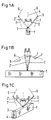
- FIGS. 1a-c the possible arrangement of one another is shown as a basic sketch the guy support inclined to the luffing plane.
- the guy support 2 is preferably on the top 3 of a symbolically shown here Cantilever element 1 arranged.
- This boom element 1 can be a basic box or a shot from a main boom of a telescopic crane or that Lattice mast element of a rigid or luffing jib.
- the in Cantilever element 1 drawn center axis 4 is ideally the luffing plane of the boom.
- the guy support 2 is in relation to the luffing plane in inclined at an angle ⁇ > 0.
- the dashed representation of the guy support 2 ' should make it clear that the guy support 2 can also be tilted towards the other side.
- the free end 5 of the guy support 2 is preferably with a clamping means 6.7 connected to a rope.
- the connection of the clamping means 6, 7 is not shown here a fixed location on the boom or a clamping device such as Piston cylinder unit or winch.
- a clamping of the clamping means 6.7 can be done can also be reached without a clamping device. Firstly, in such a way that the clamping device 6.7 can be arranged at a smaller or larger angle ⁇ and then the Guy support 2 is further inclined. Alternatively, it is also possible to use the guy support 2 telescopic and a degree of tension by changing the length to reach.
- FIG 2 is also a schematic diagram of the arrangement of two guy supports 2.1, 2.2 shown.
- the peculiarity of this arrangement is that both Guy supports 2.1,2.2 with only a single foot end 8 on the top 3 of the Cantilever element 1 are arranged.
- the respective angle of inclination ⁇ 1, ⁇ 2 can be the same or different.
- partial images a-d of FIG. 3 the possibility of is also shown as a schematic diagram Arrangement of two guy supports 2.1.2.2 shown, which have a separate foot end 8.1.8.2 have.
- the foot ends 8.1, 8.2 are in the area the top 3 of the cantilever element 1, while in the sub-picture b the foot ends 8.1,8.2 in the transition area from the top 3 to the respective side wall 9, 9 ' are located.
- sub-picture c the possibility is shown at least one foot end 8.1 outside to arrange the boom element 1.
- there is a here on top 3 Set-up aid each provided a piston-cylinder unit 28.1.28.2, which at one end the side wall 25 and with the other end in half the area of the respective Guy support 18.1 is arranged.
- the tensioning means each with a rope 29.1, is at one end via a rope thimble 31.1 Head area of the guy support 18.1 attached. From there it runs towards Boom head arranged deflection point (also not shown here) and runs back via a deflection roller 30.1 and. arranged in the head region of the guy support 18.1 thence to the winch 27.1.
- a guy clip 32.1 is arranged, which represents the rear securing for the respective guy support 18.1.
Landscapes
- Engineering & Computer Science (AREA)
- Mechanical Engineering (AREA)
- Jib Cranes (AREA)
Abstract
Die Erfindung betrifft einen Teleskopkran bestehend aus einem Unterwagen, einem
drehbar darauf angeordneten Oberwagen, einem Gegengewicht und einem Ausleger,
der mindestens einen Hauptausleger mit einem Grundkasten und mindestens einen
darin ein- und ausschiebbaren Teleskopschuss aufweist.
Erfindungsgemäß ist am Ausleger mindestens eine zumindest gegenüber der
Wippebene geneigte Abspannstütze (2) angeordnet, die mit einem im Wesentlichen in
Längsrichtung des Auslegers verlaufenden Spannmittel (6,7) verbunden ist, wobei die
Neigung der Abspannstütze (2) so gewählt ist, dass die auf den Ausleger wirkende
seitliche Belastung teilweise oder vollständig durch die Abspannung aufgenommen
wird.
According to the invention, at least one guy support (2), which is inclined at least with respect to the luffing plane, is arranged on the boom, which is connected to a tensioning means (6, 7) running essentially in the longitudinal direction of the boom, the inclination of the guy support (2) being selected such that the lateral load acting on the boom is partially or completely absorbed by the guying.
Description
Die Erfindung betrifft einen Teleskopkran bestehend aus einem Unterwagen, einem
drehbar darauf angeordneten Oberwagen, einem Gegengewicht und einem Ausleger
gemäß dem Oberbegriff des Patentanspruches 1.The invention relates to a telescopic crane consisting of an undercarriage, a
Upper carriage rotatably arranged on it, a counterweight and a boom
according to the preamble of
Teleskopkrane sind im ausgefahrenen Zustand je nach Anstellwinkel unterschiedlich großen Belastungen ausgesetzt. In Steilstellung ist oftmals die seitliche Verformung des Hauptauslegers das traglastbegrenzende Kriterium. Bei einem flachen bzw. mittleren Anstellwinkel sind die in der Einspannung der ausgefahrenen Teleskopschüsse auftretenden Belastungen ein wesentliches Kriterium für die maximale Traglast. Für den letztgenannten Belastungsfall ist als Momentenentlastung der sog. Superliftbetrieb entwickelt worden.When extended, telescopic cranes differ depending on the angle of attack exposed to great stress. The lateral deformation is often in a steep position of the main boom the criterion limiting the load capacity. With a flat or mean angles of attack are those in the clamping of the extended Telescopic shots occurring loads an essential criterion for the maximum load. For the latter case of load is a moment relief the so-called super lift operation was developed.
Teleskopkrane mit Superliftbetrieb sind seit langem bekannt (s. Auszug
Firmenprospekt Mannesmann Demag Fördertechnik; Demag AC 1600; 04/96, Seiten
5, 17 und 27). Zur Erhöhung der Traglast und zur Minderung der Durchbiegung des
ausgefahrenen Hauptauslegers ist am Grundkasten des Hauptauslegers ein auf den
Grundkasten ablegbarer Abspannbock angeordnet, der mit einer nahezu
längenunveränderbaren Abspannung mit dem Fußbereich des Hauptauslegers
einerseits und mit einer weiteren Abspannung, die im Regelfall längenveränderbar ist,
mit dem Kopf bzw. Kragen eines der inneren Teleskopschüsse andererseits
verbunden. Diese versteifende Anordnung ist anwendbar für das Grundgerät allein,
aber auch in Verbindung mit der Anordnung eines aus Gittermastteilen gebildeten
starren oder wippbaren Hilfsauslegers. Telescopic cranes with superlift operation have been known for a long time (see excerpt
Company brochure Mannesmann Demag Fördertechnik; Demag AC 1600; 04/96,
Aufgabe der Erfindung ist es, einen Teleskopkran anzugeben, dessen seitliche Verformung des Auslegers, insbesondere in Steilstellung signifikant geringer ist als bei bekannten Teleskopkranen.The object of the invention is to provide a telescopic crane, the lateral Deformation of the boom, especially in the steep position, is significantly less than at known telescopic cranes.
Diese Aufgabe wird ausgehend vom Oberbegriff in Verbindung mit den
kennzeichnenden Merkmalen des Anspruches 1 gelöst. Vorteilhafte Weiterbildungen
sind jeweils Gegenstand von Unteransprüchen.This task is based on the generic term in conjunction with the
characterizing features of
Nach der Lehre der Erfindung ist am Ausleger mindestens eine gegenüber der Wippebene geneigte Abspannstütze angeordnet, die mit einem im Wesentlichen in Längsrichtung des Auslegers verlaufenden Spannmittel verbunden ist, wobei die Neigung der Abspannstütze so gewählt ist, dass die auf den Ausleger wirkende seitliche Belastung teilweise oder vollständig durch die Abspannung aufgenommen wird. Die Neigung der Abspannstütze kann quer zur Längsrichtung oder in Längsrichtung oder überlagernd quer zur und in Längsrichtung des Auslegers erfolgen.According to the teaching of the invention, at least one is opposite to the boom Rocker plane inclined guy support arranged with a substantially in Longitudinal direction of the boom extending clamping means is connected, the The angle of the guy support is selected so that it acts on the boom lateral or partial load is absorbed by the guying becomes. The inclination of the guy support can be transverse to the longitudinal direction or in Longitudinal direction or superimposed transversely to and in the longitudinal direction of the boom.
Vorzugsweise sind auf der Oberseite des jeweiligen Auslegerelementes zwei geneigte Abspannstützen vorgesehen, wobei im Regelfall die Winkelneigung beider Abspannstützen gleich ist. Sie kann aber je nach Richtung der am Ausleger angreifenden Kräfte auch verschieden sein. Die Fußenden beider Abspannstützen können an einer gemeinsamen Stelle mit der Oberseite des Auslegers verbunden sein, aber ebenso auch versetzt zueinander. Nach einem weiteren Merkmal der Erfindung ist das Fußende wenigstens einer Abspannstütze im Übergangsbereich zwischen Oberseite oder jeweiliger Seitenwand mit dem Ausleger verbunden. Alternativ gibt es auch die Möglichkeit, das Fußende wenigstens einer Abspannstütze auf einen quer zur Längsachse des Auslegers und über diesen hinauskragenden Träger anzuordnen.Preferably, two are inclined on the top of the respective boom element Guy braces are provided, usually the angular inclination of both Guy supports are the same. However, depending on the direction of the boom attacking forces may also be different. The foot ends of both guy supports can be connected to the top of the boom at a common location, but also offset from each other. According to a further feature of the invention is the foot end of at least one guy support in the transition area between Top side or respective side wall connected to the boom. Alternatively there is also the possibility to cross the foot end of at least one guy support To arrange the longitudinal axis of the boom and overhanging this beam.
Die vorgeschlagene Anordnung hat den Vorteil, dass je nach Winkelstellung der Abspannstützen der Anteil der Abspann kraft, der in die Seitenrichtung wirksam wird, stufenlos oder kontinuierlich verändert werden kann. Im Falle der Anordnung von zwei versetzt angeordneten Abspannstützen bedeutet dies, dass in der einen Extremlage, d. h. in der Vertikalstellung, die beiden parallel stehenden Abspannstützen die gleiche Wirkung im Sinne eines Superliftbetriebes haben wie der bekannte Abspannbock. In einer Winkelstellung <90° bis >0° für die beiden Abspannstützen wird die wirksame Spannkraft aufgeteilt in eine Komponente Superliftbetrieb und eine Komponente seitliche Abspannung. In der zweiten Extremlage, d. h. in der Horizontalstellung, bewirken die beiden Abspannstützen nur eine Verstärkung in beide Seitenrichtungen.The proposed arrangement has the advantage that, depending on the angular position Guy supports: the amount of guy force that acts in the lateral direction can be changed continuously or continuously. In the case of the arrangement of two this means that in one extreme position, d. H. in the vertical position, the two guy supports in parallel are the same Effect in the sense of a superlift operation like the well-known guy stand. In an angular position <90 ° to> 0 ° for the two guy supports becomes the effective one Clamping force divided into a superlift operation component and a component lateral guying. In the second extreme position, i.e. H. in the horizontal position, the two guy supports only reinforce in both directions.
Das jeweilig freie Kopfende der Abspannstütze ist über ein erstes Spannmittel wahlweise mit dem Unterwagen, dem Oberwagen, dem Fußbereich des Auslegers, dem festen oder separat geführten Gegengewicht oder dem Boden in Richtung Fußende des Auslegers und über ein weiteres Spannmittel mit einer ausgewählten Stelle des Auslegers in Richtung Auslegerkopf verbunden. Die jeweils gewünschte Winkelstellung der Abspannstützen kann stufenweise oder kontinuierlich über ein Verschwenken der Abspannstützen eingestellt werden. Damit ist auch eine asymmetrische Winkeleinstellung möglich. Dies bedeutet, dass bei einer angreifenden Seitenkraft nur an einer Seite die jeweilige Abspannstütze mehr in Richtung seitlicher Abspannung geneigt wird, während die zweite Abspannstütze in einer Mittellage verbleibt.The respective free head end of the guy support is over a first clamping device optionally with the undercarriage, the uppercarriage, the foot area of the boom, the fixed or separately guided counterweight or the floor in the direction Foot end of the boom and a further clamping device with a selected one Place the boom connected in the direction of the boom head. The one you want Angular position of the guy supports can be gradual or continuous Swiveling the guy supports can be adjusted. So that's one asymmetrical angle adjustment possible. This means that when attacking Lateral force only on one side the respective guy support more towards the side Guy is inclined while the second guy support is in a central position remains.
Da auch der Abstand der Spannmittel vom Ausleger Einfluss auf die gewünschte Verstärkung hat, ist vorgesehen, die Länge der Abspannstützen in Stufen oder kontinuierlich zu verändern. Die Spannmittel können als Seil oder als Stange ausgebildet sein. Das Spannmittel bzw. die Spannmittel können mit und ohne Vorspannung angeordnet werden. Im Falle einer Vorspannung und eines nachregulierbaren Spanngrades wirkt das Spannmittel mit einer Spannvorrichtung zusammen. Vorzugsweise ist dies eine Winde oder eine Kolben-Zylinder-Einheit. Aber auch die Winkelverstellung und/oder die Längenänderung der Abspannstütze kann im Sinne einer Spannvorrichtung genutzt werden. Die Spannvorrichtungen sind wahlweise an den Abspannstützen, am Ausleger, am Ober- oder Unterwagen oder am Gegengewicht anordenbar.Since the distance of the clamping devices from the boom also influences the desired Reinforcement has been provided, the length of the guy supports in steps or to change continuously. The clamping devices can be used as a rope or as a rod be trained. The clamping device or the clamping device can be with and without Preload can be arranged. In the case of a preload and one The clamping device can be adjusted with a clamping device together. This is preferably a winch or a piston-cylinder unit. But also the angle adjustment and / or the change in length of the guy support can in Can be used as a tensioning device. The jigs are either on the guy supports, on the boom, on the superstructure or undercarriage or on Counterweight can be arranged.
Vorzugsweise werden die Abspannstützen am Kauptausleger im Bereich des Grundkastens angeordnet, insbesondere im vorderen Bereich zwischen der Anlenkung des Wippzylinders und der vorderem Lagerung. Zur kontinuierlichen Verstellung der Abspannstützen ist vorzugsweise jede Abspannstütze mit einer auf dem Grundkasten sich abstützenden Kolben-Zylinder-Einheit verbunden. Zur Anordnung der Winde weist nach einem weiteren Merkmal der Erfindung die Abspannstütze zwei Holme auf, zwischen denen die Winde anordenbar ist. The guy supports on the main boom are preferably in the area of the Basic box arranged, especially in the front area between the Linkage of the luffing cylinder and the front bearing. For continuous Adjustment of the guy supports is preferably every guy support with one on the piston-cylinder unit supported on the basic box. For Arrangement of the winch has according to a further feature of the invention Guy support on two spars, between which the winch can be arranged.
Die Ausrüstung des Teleskopauslegers kann noch ergänzt werden mit der Anordnung eines aus Gittermastteilen gebildeten starren oder wippbaren Hilfsauslegers. Auch an diese Auslegerelemente kann die vorgeschlagene seitliche Abspannung angebracht werden.The equipment of the telescopic boom can be supplemented with the arrangement a rigid or luffing jib made of lattice boom parts. Also on the proposed lateral bracing can be attached to these cantilever elements become.
Besonders wirkungsvoll kann die seitliche Abspannung eingesetzt werden, wenn der Kran mit einem Messmittel zur Erfassung der seitlichen Verformung des Auslegers versehen ist. Überschreitet die Verformung einen festgelegten zulässigen Wert, wird das mit der Abspannung verbundene Spannmittel aktiviert und die Abspannung nachgespannt. Der Grad der seitlichen Verformung kann direkt oder indirekt über Krangrößen ermittelt werden. Beispielsweise sind dies die Seilspannung, die Seillänge und Seildehnung. Aber auch über die an den Ausleger angreifenden Kräfte in Form des seitlich auftretenden Windes, der Sonneneinstrahlung sowie der im Ausleger vorherrschenden Temperaturen kann eine Aussage über den Grad der seitlichen Verformung gemacht werden.The side guying can be used particularly effectively if the Crane with a measuring device to record the lateral deformation of the boom is provided. If the deformation exceeds a specified permissible value, the tensioning device connected to the guying is activated and the guying tightened. The degree of lateral deformation can be direct or indirect Crane sizes can be determined. For example, these are the rope tension, the rope length and rope elongation. But also about the forces acting on the boom in form the side wind, the sun and the boom prevailing temperatures can make a statement about the degree of lateral Deformation can be made.
Weitere Merkmale, Vorteile und Einzelheiten der Erfindung ergeben sich aus der nachfolgenden Beschreibung von in einer Zeichnung dargestellten Ausführungsbeispiele. Es zeigen:
- Fig. 1a-1c
- als Prinzipskizze die mögliche Anordnung einer gegenüber der Wippebene geneigten Abspannstütze
Figur 2- als Prinzipskizze die Anordnung zweier geneigter Abspannstützen mit einem gemeinsamen Fußende.
- Figur3a-3d
- als Prinzipskizze die mögliche Anordnung zweier geneigter Abspannstützen mit getrennten Fußenden
Figur 4- als Prinzipskizze die Anordnung einer quer liegenden Abspannstütze
- Figur 5a
- in einer Vorderansicht ein praktisches Ausführungsbeispiel mit zwei neigbaren Abspannstützen.
- Figur 5b
- eine Seitenansicht von Figur 5a.
- 1a-1c
- as a basic sketch, the possible arrangement of a guy support inclined to the luffing plane
- Figure 2
- as a basic sketch, the arrangement of two inclined guy supports with a common foot end.
- Figure 3a-3d
- as a basic sketch, the possible arrangement of two inclined guy supports with separate foot ends
- Figure 4
- as a basic sketch, the arrangement of a transverse guy support
- Figure 5a
- in a front view a practical embodiment with two inclinable guy supports.
- Figure 5b
- a side view of Figure 5a.
In den Figuren 1a-c sind als Prinzipskizze die mögliche Anordnung einer gegenüber
der Wippebene geneigten Abspannstütze dargestellt. Die Abspannstütze 2 ist
vorzugsweise auf der Oberseite 3 eines hier symbolhaft dargestellten
Auslegerelementes 1 angeordnet. Dieses Auslegerelement 1 kann ein Grundkasten
oder ein Schuss eines Hauptauslegers eines Teleskopkranes oder das
Gittermastelement eines starren oder wippbaren Hilfsauslegers sein. Die im
Auslegerelement 1 eingezeichnete Mittelachse 4 ist im Idealfall auch die Wippebene
des Auslegers. Erfindungsgemäß ist die Abspannstütze 2 gegenüber der Wippebene in
einem Winkel α>0 geneigt. Die gestrichelte Darstellung der Abspannstütze 2' soll
verdeutlichen, dass die Abspannstütze 2 auch nach der anderen Seite hin neigbar ist.
Das freie Ende 5 der Abspannstüzte 2 ist mit einem Spannmittel 6,7 vorzugsweise
einem Seil verbunden. Nicht dargestellt ist hier die Verbindung der Spannmittel 6,7 mit
einer am Ausleger angeordneten Fixstelle oder einer Spannvorrichtung wie
Kolbenzylinder-Einheit oder Winde. Ein Spannen der Spannmittel 6,7 kann man aber
auch ohne Spannvorrichtung erreichen. Zum einen in der Weise, dass die Spannmittel
6,7 bei einem kleineren oder größeren Winkel α angeordnet werden und danach die
Abspannstütze 2 weitergeneigt wird. Alternativ ist es auch möglich, die Abspannstütze
2 teleskopartig auszubilden und durch Längenveränderung einen Spanngrad zu
erreichen.In FIGS. 1a-c, the possible arrangement of one another is shown as a basic sketch
the guy support inclined to the luffing plane. The
Im Teilbild b ist die Möglichkeit dargestellt die Abspannstütze 2 auch in der anderen
Ebene in einem Winkel β>0 zu neigen. Teilbild c zeigt die Möglichkeit, die
Abspannstütze 2 überlappend in beiden Ebenen zu neigen.In part b, the possibility of the
In Figur 2 ist ebenfalls in einer Prinzipskizze die Anordnung zweier Abspannstützen
2.1, 2.2 dargestellt. Die Besonderheit bei dieser Anordnung ist, dass beide
Abspannstützen 2.1,2.2 mit nur einem einzigen Fußende 8 auf der Oberseite 3 des
Auslegerelementes 1 angeordnet sind. Der jeweilige Neigungswinkel α1, α2 kann
gleich oder verschieden sein.In Figure 2 is also a schematic diagram of the arrangement of two guy supports
2.1, 2.2 shown. The peculiarity of this arrangement is that both
Guy supports 2.1,2.2 with only a
In Teilbildern a-d von Figur 3 sind ebenfalls als Prinzipskizze die Möglichkeit der
Anordnung zweier Abspannstützen 2.1,2.2 dargestellt, die ein getrenntes Fußende
8.1,8.2 aufweisen. Im ersten Teilbild a befinden sich die Fußenden 8.1,8.2 im Bereich
der Oberseite 3 des Auslegerelementes 1, während im Teilbild b die Fußenden 8.1,8.2
im Übergangsbereich von der Oberseite 3 zur jeweiligen Seitenwand 9,9' sich
befinden.In partial images a-d of FIG. 3, the possibility of is also shown as a schematic diagram
Arrangement of two guy supports 2.1.2.2 shown, which have a separate foot end
8.1.8.2 have. In the first partial image a, the foot ends 8.1, 8.2 are in the area
the
Im Teilbild c ist die Möglichkeit dargestellt zumindestens ein Fußende 8.1 außerhalb
des Auslegerelementes 1 anzuordnen. Dazu ist auf der Oberseite 3 ein hier nach
Rüsthilfe je eine Kolben-Zylinder-Einheit 28.1,28.2 vorgesehen, die an einem Ende an
der Seitenwand 25 und mit dem anderen Ende im hälftigen Bereich der jeweiligen
Abspannstütze 18.1 angeordnet ist.In sub-picture c the possibility is shown at least one foot end 8.1 outside
to arrange the
Das Spannmittel, je ein Seil 29.1 ist mit einem Ende über eine Seilkausche 31.1 am Kopfbereich der Abspannstütze 18.1 befestigt. Von dort läuft es zum in Richtung Auslegerkopf angeordneten Umlenkpunkt (auch hier nicht dargestellt) und läuft zurück über ein im Kopfbereich der Abspannstütze 18.1 angeordneten Umlenkrolle 30.1 und von dort zur Winde 27.1.The tensioning means, each with a rope 29.1, is at one end via a rope thimble 31.1 Head area of the guy support 18.1 attached. From there it runs towards Boom head arranged deflection point (also not shown here) and runs back via a deflection roller 30.1 and. arranged in the head region of the guy support 18.1 thence to the winch 27.1.
Auf der rückwärtigen Seite im Kopfbereich der Abspannstütze 18.1 ist eine
Abspannspange 32.1 angeordnet, die die rückseitige Sicherung für die jeweilige
Abspannstütze 18.1 darstellt.
Claims (30)
dadurch gekennzeichnet,
dass am Ausleger mindestens eine zumindest gegenüber der Wippebene geneigte Abspannstütze (2) angeordnet ist, die mit einem im Wesentlichen in Längsrichtung des Auslegers verlaufenden Spannmittel (6,7) verbunden ist, wobei die Neigung der Abspannstütze (2) so gewählt ist, dass die auf den Ausleger wirkende seitliche Belastung teilweise oder vollständig durch die Abspannung aufgenommen wird.Telescopic crane consisting of an undercarriage, an upper carriage rotatably arranged on it, a counterweight and a boom that has at least one main boom with a basic box and at least one telescopic section that can be pushed in and out,
characterized,
that at least one guy support (2) inclined at least with respect to the luffing plane is arranged on the boom, which is connected to a tensioning means (6, 7) running essentially in the longitudinal direction of the boom, the inclination of the guy support (2) being selected such that the lateral load acting on the boom is partially or completely absorbed by the guying.
dadurch gekennzeichnet,
dass auf der Oberseite (3) des jeweiligen Auslegerelementes (1) mindestens eine zumindest gegenüber der Wippebene geneigte Abspannstütze (2) angeordnet ist.Telescopic crane according to claim 1,
characterized,
that at least one guy support (2) inclined at least with respect to the luffing plane is arranged on the upper side (3) of the respective cantilever element (1).
dadurch gekennzeichnet,
dass am Ausleger mindestens eine Abspannstütze (2) angeordnet ist, die zu der Ebene, die aufgespannt wird, durch die in Längsrichtung liegende Mitte (4) des Auslegers und der Last, einen quer zur Längsachse des Auslegers liegenden Winkel α>0 aufweist.Telescopic crane according to claim 1 and 2,
characterized,
that at least one guy support (2) is arranged on the boom, which has an angle α> 0 transverse to the longitudinal axis of the boom to the plane that is spanned by the longitudinal center (4) of the boom and the load.
dadurch gekennzeichnet,
dass am Ausleger mindestens eine Abspannstütze (2) angeordnet ist, die in der Ebene, die aufgespannt wird durch die in Längsrichtung liegende Mitte (4) des Auslegers und der Last, einen zu einem auf den Ausleger gefällten Lot einen Winkel β>0 aufweist. Telescopic crane according to claim 1 and 2,
characterized,
that at least one guy support (2) is arranged on the boom, which, in the plane that is spanned by the longitudinal center (4) of the boom and the load, has an angle β> 0 to a solder that has fallen onto the boom.
dadurch gekennzeichnet,
dass die Abspannstütze (2) überlagernd mit einem Winkel α>0 und einem Winkel β>0 geneigt ist.Telescopic crane according to claims 1 to 4,
characterized,
that the guy support (2) is inclined overlapping with an angle α> 0 and an angle β> 0.
dadurch gekennzeichnet,
dass auf der Oberseite (3) des Auslegers zwei geneigte Abspannstützen (2.1;2.2) angeordnet sind.Telescopic crane according to one of claims 1 to 5,
characterized,
that two inclined guy supports (2.1; 2.2) are arranged on the top (3) of the boom.
dadurch gekennzeichnet,
dass an einem ausgewählten Ort der Oberseite (3) des Auslegers ein Paar geneigte Abspannstützen (2.1;2.2) vorgesehen sind, wovon sich eine Abspannstütze (2.1) nach rechts und eine (2.2) nach links zur Seite erstreckt.Telescopic crane according to claim 6,
characterized,
that a pair of inclined guy supports (2.1; 2.2) are provided at a selected location on the upper side (3) of the boom, one guy support (2.1) extending to the right and one (2.2) to the left.
dadurch gekennzeichnet,
dass das Fußende (8) beider Abspannstützen (2.1;2.2) an einer gemeinsamen Stelle mit der Oberseite (3) des Auslegers verbunden ist.Telescopic crane according to claim 7,
characterized,
that the foot end (8) of both guy supports (2.1; 2.2) is connected at a common point to the top (3) of the boom.
dadurch gekennzeichnet,
dass die Fußenden (8.1;8.2) beider Abspannstützen (2.1;2.2) versetzt zueinander mit der Oberseite (3) des Auslegers verbunden sind.Telescopic crane according to claim 7,
characterized,
that the foot ends (8.1; 8.2) of both guy supports (2.1; 2.2) are connected to the top (3) of the boom offset from each other.
dadurch gekennzeichnet,
dass das Fußende (8.1;8.2) wenigstens einer Abspannstütze (2.1;2.2) im Übergangsbereich zwischen Oberseite (3) und jeweiliger Seitenwand (9,9') mit dem Ausleger verbunden ist.Telescopic crane according to claim 7 and 9,
characterized,
that the foot end (8.1; 8.2) of at least one guy support (2.1; 2.2) is connected to the boom in the transition area between the upper side (3) and the respective side wall (9,9 ').
dadurch gekennzeichnet,
dass das Fußende (8.1) wenigstens einer Abspannstütze (2.1) auf einem quer zur Längsachse des Auslegers und über diesen hinauskragenden Träger (10) angeordnet ist.Telescopic crane according to claim 7 and 9,
characterized,
that the foot end (8.1) of at least one guy support (2.1) is arranged on a support (10) projecting transversely to the longitudinal axis of the boom and beyond it.
dadurch gekennzeichnet,
dass das freie Kopfende (5) der Abspannstütze (2) über ein erstes Spannmittel (7) wahlweise mit dem Oberwagen, dem Unterwagen, dem Fußbereich des Auslegers, dem festen oder separat geführten Gegengewicht oder dem Boden in Richtung Fußende des Auslegers und über ein weiteres Spannmittel (6) mit einer ausgewählten Stelle des Hauptauslegers oder einem Teil der Auslegerverlängerung in Richtung Kopfende des Auslegers verbunden ist.Telescopic crane according to one of claims 1 to 11,
characterized,
that the free head end (5) of the guy support (2) via a first tensioning device (7) either with the uppercarriage, the undercarriage, the foot area of the boom, the fixed or separately guided counterweight or the floor towards the foot end of the boom and another Clamping means (6) is connected to a selected point of the main boom or part of the boom extension in the direction of the head end of the boom.
dadurch gekennzeichnet,
dass die jeweils gewählte Winkelstellung stufenweise oder kontinuierlich über ein Verschwenken der Abspannstütze (n) (2.1;2.2) einstellbar ist.Telescopic crane according to one of claims 1 to 12,
characterized,
that the respectively selected angular position can be adjusted in stages or continuously by swiveling the guy support (s) (2.1; 2.2).
dadurch gekennzeichnet,
dass die Länge der Abspannstütze (n) in Stufen oder kontinuierlich veränderbar ist.Telescopic crane according to one of claims 1 to 13,
characterized,
that the length of the guy support (s) can be changed in steps or continuously.
dadurch gekennzeichnet,
dass das Spannmittel ein Seil oder eine Stange ist.Telescopic crane according to one of claims 1 to 14,
characterized,
that the tensioning device is a rope or a rod.
dadurch gekennzeichnet,
dass das Spannmittel mit einer Spannvorrichtung zusammenwirkt.Telescopic crane according to one of claims 1 to 15,
characterized,
that the clamping device interacts with a clamping device.
dadurch gekennzeichnet,
dass die Winkelverstellung und/oder die Längenveränderung der Abspannstütze im Sinne einer Spannvorrichtung genutzt wird.Telescopic crane according to claim 16,
characterized,
that the angle adjustment and / or the length change of the guy support is used in the sense of a tensioning device.
dadurch gekennzeichnet,
dass die Spannvorrichtung eine Winde (27.1;27.2) oder eine Kolben-Zylinder-Einheit ist.Telescopic crane according to claim 16,
characterized,
that the tensioning device is a winch (27.1; 27.2) or a piston-cylinder unit.
dadurch gekennzeichnet,
dass für die Abspannung mindestens zwei separat ansteuerbare Spannvorrichtungen vorgesehen sind.Telescopic crane according to one of claims 1 to 18,
characterized,
that at least two separately controllable tensioning devices are provided for the guying.
dadurch gekennzeichnet,
dass die Spannvorrichtung (en) wahlweise an der Abspannstütze (18.1;18.2), am Oberwagen, am Unterwagen, am Hauptausleger, am Gegengewicht oder an der Auslegerverlängerung angeordnet sind.Telescopic crane according to claim 19,
characterized,
that the tensioning device (s) are optionally arranged on the guy support (18.1; 18.2), on the superstructure, on the undercarriage, on the main boom, on the counterweight or on the boom extension.
dadurch gekennzeichnet,
dass ein Paar Abspannstützen (18.1;18.2) am Hauptausleger im Bereich des Grundkastens (13) angeordnet sind.Telescopic crane according to one of claims 1 to 20,
characterized,
that a pair of guy supports (18.1; 18.2) are arranged on the main boom in the area of the base box (13).
dadurch gekennzeichnet,
dass die Abspannstützen im vorderen Bereich zwischen der Anlenkung des Wippzylinders und der vorderen Lagerung am Grundkasten (13) angeordnet sind.Telescopic crane according to claim 21,
characterized,
that the guy supports are arranged in the front area between the articulation of the luffing cylinder and the front bearing on the basic box (13).
dadurch gekennzeichnet,
dass die freien Kopfenden der Abspannstützen in Richtung Auslegerkopf mit dem Kopf oder Kragen eines der inneren Teleskopschüsse verbunden sind. Telescopic crane according to one of claims 1 to 22,
characterized,
that the free head ends of the guy supports in the direction of the boom head are connected to the head or collar of one of the inner telescopic sections.
dadurch gekennzeichnet,
dass für die seitliche Neigbarkeit jede Abspannstütze (18.1;18.2) mit einer auf dem Grundkasten sich abstützenden Kolben-Zylinder-Einheit (20.1;20.2) verbunden ist.Telescopic crane according to claims 21 to 23,
characterized,
that each guy support (18.1; 18.2) is connected to a piston-cylinder unit (20.1; 20.2) supported on the basic box for lateral inclination.
dadurch gekennzeichnet,
dass jede Abspannstütze (18.1;18.2) zwei in etwa parallel liegende Holme (21.1;22.1;21.2;22.2) aufweist.Telescopic crane according to claims 21 to 24,
characterized,
that each guy support (18.1; 18.2) has two approximately parallel bars (21.1; 22.1; 21.2; 22.2).
dadurch gekennzeichnet,
dass zwischen den Holmen (21.1;22.1;21.2;22.2) der jeweiligen Abspannstützen (18.1;18.2) eine Winde (27.1;27.2) angeordnet ist.Telescopic crane according to claim 25,
characterized,
that a winch (27.1; 27.2) is arranged between the spars (21.1; 22.1; 21.2; 22.2) of the respective guy supports (18.1; 18.2).
dadurch gekennzeichnet,
dass am Kopf des inneren Teleskopschusses ein aus Gittermastteilen gebildeter starrer Hilfsausleger befestigt ist.Telescopic crane according to one of claims 1 to 26,
characterized,
that a rigid auxiliary boom formed from lattice boom parts is attached to the head of the inner telescopic section.
dadurch gekennzeichnet,
dass am Kopf des innersten Teleskopschusses ein aus Gittermastteilen gebildeter wippbarer Hilfsausleger mit mindestens einer Wippstütze befestigt ist.Telescopic crane according to one of claims 1 to 26,
characterized,
that at the head of the innermost telescopic section a luffing jib made of lattice boom parts is attached with at least one luffing support.
dadurch gekennzeichnet,
dass zur Erfassung der seitlichen Verformung des Auslegers ein Messmittel vorgesehen ist, das steuerungsmäßig mit einer den Spannungsgrad der seitlichen Abspannung beeinflussenden Spannvorrichtung verknüpft ist. Telescopic crane according to one of claims 1 to 28,
characterized,
that a measuring device is provided for detecting the lateral deformation of the boom, which is linked in terms of control to a tensioning device influencing the degree of tension of the lateral guying.
dadurch gekennzeichnet,
dass die seitliche Verformung direkt oder indirekt über Krangrößen wie beispielsweise Seilspannung, Seillänge, Seildehnung sowie die am Ausleger angreifenden Kräfte, in Form des seitlichen auftretenden Windes, der Sonneneinstrahlung sowie der am Hauptausleger vorherrschenden Temperaturen erfassbar ist.Telescopic crane according to claim 29,
characterized,
that the lateral deformation can be detected directly or indirectly via crane sizes such as rope tension, rope length, rope elongation as well as the forces acting on the boom, in the form of the lateral wind, solar radiation and the temperatures prevailing on the main boom.
Priority Applications (3)
| Application Number | Priority Date | Filing Date | Title |
|---|---|---|---|
| EP03014531A EP1354842B1 (en) | 1999-06-28 | 2000-06-26 | Telescopic crane |
| DE20018742U DE20018742U1 (en) | 1999-06-28 | 2000-06-26 | Telescopic crane |
| DE20023223U DE20023223U1 (en) | 1999-06-28 | 2000-06-26 | telescopic crane |
Applications Claiming Priority (4)
| Application Number | Priority Date | Filing Date | Title |
|---|---|---|---|
| DE19930537 | 1999-06-28 | ||
| DE19930537 | 1999-06-28 | ||
| DE10022658A DE10022658B4 (en) | 1999-06-28 | 2000-04-28 | telescopic crane |
| DE10022658 | 2000-04-28 |
Related Child Applications (1)
| Application Number | Title | Priority Date | Filing Date |
|---|---|---|---|
| EP03014531A Division EP1354842B1 (en) | 1999-06-28 | 2000-06-26 | Telescopic crane |
Publications (4)
| Publication Number | Publication Date |
|---|---|
| EP1065166A2 true EP1065166A2 (en) | 2001-01-03 |
| EP1065166A3 EP1065166A3 (en) | 2002-05-08 |
| EP1065166B1 EP1065166B1 (en) | 2003-08-13 |
| EP1065166B2 EP1065166B2 (en) | 2009-02-18 |
Family
ID=26005614
Family Applications (1)
| Application Number | Title | Priority Date | Filing Date |
|---|---|---|---|
| EP00250210A Expired - Lifetime EP1065166B2 (en) | 1999-06-28 | 2000-06-26 | Telescopic crane |
Country Status (5)
| Country | Link |
|---|---|
| EP (1) | EP1065166B2 (en) |
| JP (1) | JP5013630B2 (en) |
| AT (2) | ATE285980T1 (en) |
| DE (2) | DE20022790U1 (en) |
| ES (2) | ES2204452T3 (en) |
Cited By (6)
| Publication number | Priority date | Publication date | Assignee | Title |
|---|---|---|---|---|
| DE20020974U1 (en) * | 2000-12-12 | 2002-04-25 | Liebherr-Werk Ehingen Gmbh, 89584 Ehingen | mobile crane |
| WO2002100756A1 (en) * | 2001-06-11 | 2002-12-19 | Terex-Demag Gmbh & Co. Kg | Mobile crane comprising a telescopic principal jib |
| EP1426321A1 (en) * | 2002-12-06 | 2004-06-09 | Liebherr-Werk Ehingen GmbH | Mobile crane with two part boom |
| WO2005092775A1 (en) | 2004-03-26 | 2005-10-06 | Terex-Demag Gmbh & Co. Kg | Mobile crane sytsem comprising a mobile crane and an auxiliary device for assembly of a bracing device |
| NL1037444C2 (en) * | 2009-11-04 | 2011-05-11 | Bastiaan Jong | CRANE. |
| EP2998264A1 (en) | 2008-05-06 | 2016-03-23 | Terex Cranes Germany GmbH | Laterally released lattice mast |
Families Citing this family (11)
| Publication number | Priority date | Publication date | Assignee | Title |
|---|---|---|---|---|
| DE10315989B4 (en) * | 2003-04-08 | 2007-10-25 | Grove U.S. Llc | Clamping system for a mobile telescopic crane |
| JP2005162392A (en) * | 2003-12-02 | 2005-06-23 | Tadano Ltd | Mobile crane |
| JP2006206233A (en) * | 2005-01-27 | 2006-08-10 | Tadano Ltd | Telescopic boom horizontal deflection restricting device for travelling crane |
| JP2006306546A (en) * | 2005-04-27 | 2006-11-09 | Tadano Ltd | Crane device with jib |
| DE202005016743U1 (en) * | 2005-10-25 | 2007-03-29 | Liebherr-Werk Ehingen Gmbh | Crane comprises a bracing device having two brace supports hinged on an auxiliary boom and inclined opposite a rocker surface |
| AT10273U1 (en) * | 2007-05-03 | 2008-12-15 | Palfinger Ag | ADJUSTMENT MECHANISM FOR A WINCH |
| JP5271122B2 (en) * | 2009-03-11 | 2013-08-21 | 株式会社タダノ | Boom and jib lateral deflection suppressing device for boom working vehicle with jib |
| JP5629160B2 (en) * | 2010-08-18 | 2014-11-19 | 株式会社タダノ | Mobile crane |
| JP5635331B2 (en) * | 2010-08-18 | 2014-12-03 | 株式会社タダノ | Mobile crane |
| JP5649870B2 (en) * | 2010-08-20 | 2015-01-07 | 株式会社タダノ | Mobile crane |
| DE102020215260B4 (en) * | 2020-12-03 | 2022-06-23 | Tadano Faun Gmbh | Method of operating a crane and crane |
Family Cites Families (11)
| Publication number | Priority date | Publication date | Assignee | Title |
|---|---|---|---|---|
| DE1751383U (en) † | 1957-06-04 | 1957-08-29 | Horst Vesper | CRANE JIB IN SHELL CONSTRUCTION. |
| JPS4737785Y1 (en) * | 1969-02-28 | 1972-11-15 | ||
| DE3030820C2 (en) † | 1979-08-17 | 1987-01-29 | Coles Cranes Ltd., Sunderland, Tyne and Wear | Mobile crane with a telescopic boom |
| DE3113763A1 (en) * | 1981-04-04 | 1982-10-28 | Mannesmann AG, 4000 Düsseldorf | Vehicle crane with telescopic jib |
| JPS59164284A (en) * | 1983-03-07 | 1984-09-17 | Nissan Motor Co Ltd | Rig-structure of sailing vessel |
| JPH0450304Y2 (en) * | 1987-09-02 | 1992-11-26 | ||
| DE3840408A1 (en) † | 1988-03-23 | 1989-10-05 | Liebherr Werk Ehingen | Mobile crane with telescopic jib |
| DE4337415C2 (en) * | 1993-10-27 | 1996-09-26 | Mannesmann Ag | Crane, especially a large mobile crane |
| DE19606109A1 (en) * | 1995-12-12 | 1997-06-19 | Liebherr Werk Ehingen | Mobile crane |
| DE29720972U1 (en) † | 1997-11-26 | 1999-03-25 | Ec Engineering + Consulting Spezialmaschinen Gmbh, 89079 Ulm | Telescopic boom |
| DE19802187C2 (en) † | 1998-01-16 | 1999-11-25 | Mannesmann Ag | Device for bracing a superlift device of a telescopic crane |
-
2000
- 2000-04-28 DE DE20022790U patent/DE20022790U1/en not_active Expired - Lifetime
- 2000-04-28 DE DE20023565U patent/DE20023565U1/en not_active Expired - Lifetime
- 2000-06-26 EP EP00250210A patent/EP1065166B2/en not_active Expired - Lifetime
- 2000-06-26 AT AT03014531T patent/ATE285980T1/en not_active IP Right Cessation
- 2000-06-26 AT AT00250210T patent/ATE247071T1/en not_active IP Right Cessation
- 2000-06-26 ES ES00250210T patent/ES2204452T3/en not_active Expired - Lifetime
- 2000-06-26 ES ES03014531T patent/ES2235131T3/en not_active Expired - Lifetime
- 2000-06-28 JP JP2000194127A patent/JP5013630B2/en not_active Expired - Lifetime
Cited By (9)
| Publication number | Priority date | Publication date | Assignee | Title |
|---|---|---|---|---|
| DE20020974U1 (en) * | 2000-12-12 | 2002-04-25 | Liebherr-Werk Ehingen Gmbh, 89584 Ehingen | mobile crane |
| EP1215161A1 (en) * | 2000-12-12 | 2002-06-19 | Liebherr-Werk Ehingen GmbH | Mobile crane |
| WO2002100756A1 (en) * | 2001-06-11 | 2002-12-19 | Terex-Demag Gmbh & Co. Kg | Mobile crane comprising a telescopic principal jib |
| US7172082B2 (en) | 2001-06-11 | 2007-02-06 | Terex-Demag Gmbh & Co. Kg | Mobile crane with a telescopic main boom |
| EP1426321A1 (en) * | 2002-12-06 | 2004-06-09 | Liebherr-Werk Ehingen GmbH | Mobile crane with two part boom |
| US7219810B2 (en) | 2002-12-06 | 2007-05-22 | Liebherr-Werk Ehingen Gmbh | Mobile crane with elongated boom |
| WO2005092775A1 (en) | 2004-03-26 | 2005-10-06 | Terex-Demag Gmbh & Co. Kg | Mobile crane sytsem comprising a mobile crane and an auxiliary device for assembly of a bracing device |
| EP2998264A1 (en) | 2008-05-06 | 2016-03-23 | Terex Cranes Germany GmbH | Laterally released lattice mast |
| NL1037444C2 (en) * | 2009-11-04 | 2011-05-11 | Bastiaan Jong | CRANE. |
Also Published As
| Publication number | Publication date |
|---|---|
| EP1065166A3 (en) | 2002-05-08 |
| EP1065166B1 (en) | 2003-08-13 |
| ES2235131T3 (en) | 2005-07-01 |
| ATE247071T1 (en) | 2003-08-15 |
| JP5013630B2 (en) | 2012-08-29 |
| DE20022790U1 (en) | 2002-07-04 |
| DE20023565U1 (en) | 2004-11-25 |
| ATE285980T1 (en) | 2005-01-15 |
| ES2204452T3 (en) | 2004-05-01 |
| EP1065166B2 (en) | 2009-02-18 |
| JP2001058791A (en) | 2001-03-06 |
Similar Documents
| Publication | Publication Date | Title |
|---|---|---|
| DE10022658A1 (en) | Telescopic crane | |
| DE10315989B4 (en) | Clamping system for a mobile telescopic crane | |
| EP1065166A2 (en) | Telescopic crane | |
| DE20020974U1 (en) | mobile crane | |
| DE102011119654B4 (en) | Mobile work machine, in particular vehicle crane | |
| AT523743B1 (en) | Mobile crane and method for reducing the load on its boom | |
| DE10128986A1 (en) | Mobile crane has load increasing device permanently connected to main jib part and with individual weight of telescopic extensions each reduced to avoid exceeding maximum permissible weight without having to reduce number of extensions | |
| EP3793930B1 (en) | Support for the rear anchoring line of a telescopic crane | |
| DE60310177T2 (en) | Frame with hinge devices for support arms | |
| DE20107984U1 (en) | Mobile crane with luffing jib | |
| DE69810981T2 (en) | Technique for erecting the mast for a telescopic crane | |
| EP0443353B1 (en) | Vehicle mounted telescopic crane | |
| DE202013011183U1 (en) | Telescopic super lift mast | |
| DE202005005627U1 (en) | Crane with anchoring device for moving loads has at least one anchoring support fixed to rocker cylinder | |
| DE20203443U1 (en) | Telescopic jib has bracing supports pivotable around only one single respective pivot point inclined do that supports spread out in V-form during orientation into operating position | |
| DE102019122071B3 (en) | Telescopic boom with fold-out mast | |
| DE20023869U1 (en) | Telescopic crane incorporates a bottom carriage with a top carriage turning on it, a counter weight and a jib having a main jib with a base casing and a telescopic projection sliding in and out. | |
| DE102022128653B4 (en) | Mobile crane with lattice boom, lattice boom and method for assembling such a crane | |
| DE20023223U1 (en) | telescopic crane | |
| DE20023369U1 (en) | Telescopic crane incorporates a bottom carriage with a top carriage turning on it, a counter weight and a jib having a main jib with a base casing and a telescopic projection sliding in and out. | |
| DE102023119815B4 (en) | Mounting frame, mobile crane and method for mounting a guying device on a telescopic boom | |
| DE202004016639U1 (en) | mobile crane | |
| DE1781048C3 (en) | Multi-part telescopic mast for lift trucks | |
| DE20023867U1 (en) | Telescopic crane incorporates a bottom carriage with a top carriage turning on it, a counter weight and a jib having a main jib with a base casing and a telescopic projection sliding in and out. | |
| DE20108816U1 (en) | crane |
Legal Events
| Date | Code | Title | Description |
|---|---|---|---|
| PUAI | Public reference made under article 153(3) epc to a published international application that has entered the european phase |
Free format text: ORIGINAL CODE: 0009012 |
|
| AK | Designated contracting states |
Kind code of ref document: A2 Designated state(s): AT BE CH CY DE DK ES FI FR GB GR IE IT LI LU MC NL PT SE |
|
| AX | Request for extension of the european patent |
Free format text: AL;LT;LV;MK;RO;SI |
|
| 17P | Request for examination filed |
Effective date: 20011030 |
|
| PUAL | Search report despatched |
Free format text: ORIGINAL CODE: 0009013 |
|
| AK | Designated contracting states |
Kind code of ref document: A3 Designated state(s): AT BE CH CY DE DK ES FI FR GB GR IE IT LI LU MC NL PT SE |
|
| AX | Request for extension of the european patent |
Free format text: AL;LT;LV;MK;RO;SI |
|
| RAP1 | Party data changed (applicant data changed or rights of an application transferred) |
Owner name: DEMAG MOBILE CRANES GMBH & CO. KG |
|
| GRAH | Despatch of communication of intention to grant a patent |
Free format text: ORIGINAL CODE: EPIDOS IGRA |
|
| AKX | Designation fees paid |
Designated state(s): AT BE CH CY DE DK ES FI FR GB GR IE IT LI LU MC NL PT SE |
|
| GRAH | Despatch of communication of intention to grant a patent |
Free format text: ORIGINAL CODE: EPIDOS IGRA |
|
| GRAH | Despatch of communication of intention to grant a patent |
Free format text: ORIGINAL CODE: EPIDOS IGRA |
|
| RAP1 | Party data changed (applicant data changed or rights of an application transferred) |
Owner name: TEREX-DEMAG GMBH & CO. KG |
|
| GRAA | (expected) grant |
Free format text: ORIGINAL CODE: 0009210 |
|
| AK | Designated contracting states |
Designated state(s): AT BE CH CY DE DK ES FI FR GB GR IE IT LI LU MC NL PT SE |
|
| PG25 | Lapsed in a contracting state [announced via postgrant information from national office to epo] |
Ref country code: FI Free format text: LAPSE BECAUSE OF FAILURE TO SUBMIT A TRANSLATION OF THE DESCRIPTION OR TO PAY THE FEE WITHIN THE PRESCRIBED TIME-LIMIT Effective date: 20030813 Ref country code: IE Free format text: LAPSE BECAUSE OF FAILURE TO SUBMIT A TRANSLATION OF THE DESCRIPTION OR TO PAY THE FEE WITHIN THE PRESCRIBED TIME-LIMIT Effective date: 20030813 Ref country code: CY Free format text: LAPSE BECAUSE OF FAILURE TO SUBMIT A TRANSLATION OF THE DESCRIPTION OR TO PAY THE FEE WITHIN THE PRESCRIBED TIME-LIMIT Effective date: 20030813 |
|
| REG | Reference to a national code |
Ref country code: GB Ref legal event code: FG4D Free format text: NOT ENGLISH |
|
| RIN1 | Information on inventor provided before grant (corrected) |
Inventor name: KUHN, ROLAND, DIPL.-ING. Inventor name: MARX, MARKUS Inventor name: ZIMMER, WALTER Inventor name: IRSCH, MICHAEL, DIPL.-ING. Inventor name: STOWASSER, WALTER, DIPL.-ING. Inventor name: FERY, JENS, DIPL.-ING. Inventor name: FRIES, OLIVER, DR.-ING. Inventor name: CONRAD, FRANK, DIPL.-ING. |
|
| REG | Reference to a national code |
Ref country code: CH Ref legal event code: EP |
|
| REG | Reference to a national code |
Ref country code: CH Ref legal event code: NV Representative=s name: DR. LUSUARDI AG |
|
| REG | Reference to a national code |
Ref country code: IE Ref legal event code: FG4D Free format text: GERMAN |
|
| REF | Corresponds to: |
Ref document number: 50003246 Country of ref document: DE Date of ref document: 20030918 Kind code of ref document: P |
|
| PG25 | Lapsed in a contracting state [announced via postgrant information from national office to epo] |
Ref country code: DK Free format text: LAPSE BECAUSE OF FAILURE TO SUBMIT A TRANSLATION OF THE DESCRIPTION OR TO PAY THE FEE WITHIN THE PRESCRIBED TIME-LIMIT Effective date: 20031113 Ref country code: GR Free format text: LAPSE BECAUSE OF FAILURE TO SUBMIT A TRANSLATION OF THE DESCRIPTION OR TO PAY THE FEE WITHIN THE PRESCRIBED TIME-LIMIT Effective date: 20031113 Ref country code: SE Free format text: LAPSE BECAUSE OF FAILURE TO SUBMIT A TRANSLATION OF THE DESCRIPTION OR TO PAY THE FEE WITHIN THE PRESCRIBED TIME-LIMIT Effective date: 20031113 |
|
| GBT | Gb: translation of ep patent filed (gb section 77(6)(a)/1977) |
Effective date: 20031209 |
|
| PG25 | Lapsed in a contracting state [announced via postgrant information from national office to epo] |
Ref country code: PT Free format text: LAPSE BECAUSE OF FAILURE TO SUBMIT A TRANSLATION OF THE DESCRIPTION OR TO PAY THE FEE WITHIN THE PRESCRIBED TIME-LIMIT Effective date: 20040113 |
|
| PLBQ | Unpublished change to opponent data |
Free format text: ORIGINAL CODE: EPIDOS OPPO |
|
| PLBI | Opposition filed |
Free format text: ORIGINAL CODE: 0009260 |
|
| PLBI | Opposition filed |
Free format text: ORIGINAL CODE: 0009260 |
|
| PLBQ | Unpublished change to opponent data |
Free format text: ORIGINAL CODE: EPIDOS OPPO |
|
| 26 | Opposition filed |
Opponent name: LIEBHERR-WERK EHINGEN GMBH Effective date: 20040122 |
|
| REG | Reference to a national code |
Ref country code: IE Ref legal event code: FD4D |
|
| 26 | Opposition filed |
Opponent name: DEUTSCHE GROVE GMBH Effective date: 20040223 Opponent name: LIEBHERR-WERK EHINGEN GMBH Effective date: 20040122 |
|
| REG | Reference to a national code |
Ref country code: ES Ref legal event code: FG2A Ref document number: 2204452 Country of ref document: ES Kind code of ref document: T3 |
|
| NLR1 | Nl: opposition has been filed with the epo |
Opponent name: LIEBHERR-WERK EHINGEN GMBH |
|
| ET | Fr: translation filed | ||
| NLR1 | Nl: opposition has been filed with the epo |
Opponent name: DEUTSCHE GROVE GMBH Opponent name: LIEBHERR-WERK EHINGEN GMBH |
|
| PLAX | Notice of opposition and request to file observation + time limit sent |
Free format text: ORIGINAL CODE: EPIDOSNOBS2 |
|
| PG25 | Lapsed in a contracting state [announced via postgrant information from national office to epo] |
Ref country code: LU Free format text: LAPSE BECAUSE OF NON-PAYMENT OF DUE FEES Effective date: 20040626 |
|
| PG25 | Lapsed in a contracting state [announced via postgrant information from national office to epo] |
Ref country code: BE Free format text: LAPSE BECAUSE OF NON-PAYMENT OF DUE FEES Effective date: 20040630 Ref country code: MC Free format text: LAPSE BECAUSE OF NON-PAYMENT OF DUE FEES Effective date: 20040630 |
|
| PLAX | Notice of opposition and request to file observation + time limit sent |
Free format text: ORIGINAL CODE: EPIDOSNOBS2 |
|
| BERE | Be: lapsed |
Owner name: *TEREX-DEMAG G.M.B.H. & CO. K.G. Effective date: 20040630 |
|
| PLAX | Notice of opposition and request to file observation + time limit sent |
Free format text: ORIGINAL CODE: EPIDOSNOBS2 |
|
| PLBB | Reply of patent proprietor to notice(s) of opposition received |
Free format text: ORIGINAL CODE: EPIDOSNOBS3 |
|
| PLAQ | Examination of admissibility of opposition: information related to despatch of communication + time limit deleted |
Free format text: ORIGINAL CODE: EPIDOSDOPE2 |
|
| PLAR | Examination of admissibility of opposition: information related to receipt of reply deleted |
Free format text: ORIGINAL CODE: EPIDOSDOPE4 |
|
| PLBQ | Unpublished change to opponent data |
Free format text: ORIGINAL CODE: EPIDOS OPPO |
|
| PLAB | Opposition data, opponent's data or that of the opponent's representative modified |
Free format text: ORIGINAL CODE: 0009299OPPO |
|
| PLBP | Opposition withdrawn |
Free format text: ORIGINAL CODE: 0009264 |
|
| PGFP | Annual fee paid to national office [announced via postgrant information from national office to epo] |
Ref country code: CH Payment date: 20050614 Year of fee payment: 6 |
|
| PGFP | Annual fee paid to national office [announced via postgrant information from national office to epo] |
Ref country code: AT Payment date: 20050615 Year of fee payment: 6 |
|
| R26 | Opposition filed (corrected) |
Opponent name: DEUTSCHE GROVE GMBH Effective date: 20040223 |
|
| NLR1 | Nl: opposition has been filed with the epo |
Opponent name: DEUTSCHE GROVE GMBH |
|
| PG25 | Lapsed in a contracting state [announced via postgrant information from national office to epo] |
Ref country code: AT Free format text: LAPSE BECAUSE OF NON-PAYMENT OF DUE FEES Effective date: 20060626 |
|
| PG25 | Lapsed in a contracting state [announced via postgrant information from national office to epo] |
Ref country code: CH Free format text: LAPSE BECAUSE OF NON-PAYMENT OF DUE FEES Effective date: 20060630 Ref country code: LI Free format text: LAPSE BECAUSE OF NON-PAYMENT OF DUE FEES Effective date: 20060630 |
|
| PGFP | Annual fee paid to national office [announced via postgrant information from national office to epo] |
Ref country code: IT Payment date: 20060630 Year of fee payment: 7 |
|
| REG | Reference to a national code |
Ref country code: CH Ref legal event code: PL |
|
| PLAB | Opposition data, opponent's data or that of the opponent's representative modified |
Free format text: ORIGINAL CODE: 0009299OPPO |
|
| R26 | Opposition filed (corrected) |
Opponent name: MANITOWOC CRANE GROUP GERMANY GMBH Effective date: 20040223 |
|
| PGFP | Annual fee paid to national office [announced via postgrant information from national office to epo] |
Ref country code: ES Payment date: 20070628 Year of fee payment: 8 |
|
| NLR1 | Nl: opposition has been filed with the epo |
Opponent name: MANITOWOC CRANE GROUP GERMANY GMBH |
|
| APBP | Date of receipt of notice of appeal recorded |
Free format text: ORIGINAL CODE: EPIDOSNNOA2O |
|
| APAH | Appeal reference modified |
Free format text: ORIGINAL CODE: EPIDOSCREFNO |
|
| APBP | Date of receipt of notice of appeal recorded |
Free format text: ORIGINAL CODE: EPIDOSNNOA2O |
|
| PGFP | Annual fee paid to national office [announced via postgrant information from national office to epo] |
Ref country code: GB Payment date: 20070621 Year of fee payment: 8 |
|
| APBQ | Date of receipt of statement of grounds of appeal recorded |
Free format text: ORIGINAL CODE: EPIDOSNNOA3O |
|
| APBQ | Date of receipt of statement of grounds of appeal recorded |
Free format text: ORIGINAL CODE: EPIDOSNNOA3O |
|
| PLBP | Opposition withdrawn |
Free format text: ORIGINAL CODE: 0009264 |
|
| APBU | Appeal procedure closed |
Free format text: ORIGINAL CODE: EPIDOSNNOA9O |
|
| PLAB | Opposition data, opponent's data or that of the opponent's representative modified |
Free format text: ORIGINAL CODE: 0009299OPPO |
|
| R26 | Opposition filed (corrected) |
Opponent name: MANITOWOC CRANE GROUP GERMANY GMBH Effective date: 20040223 |
|
| PGFP | Annual fee paid to national office [announced via postgrant information from national office to epo] |
Ref country code: FR Payment date: 20070615 Year of fee payment: 8 |
|
| NLR1 | Nl: opposition has been filed with the epo |
Opponent name: MANITOWOC CRANE GROUP GERMANY GMBH |
|
| PUAH | Patent maintained in amended form |
Free format text: ORIGINAL CODE: 0009272 |
|
| STAA | Information on the status of an ep patent application or granted ep patent |
Free format text: STATUS: PATENT MAINTAINED AS AMENDED |
|
| 27A | Patent maintained in amended form |
Effective date: 20090218 |
|
| AK | Designated contracting states |
Kind code of ref document: B2 Designated state(s): AT BE CH CY DE DK ES FI FR GB GR IE IT LI LU MC NL PT SE |
|
| GBPC | Gb: european patent ceased through non-payment of renewal fee |
Effective date: 20080626 |
|
| REG | Reference to a national code |
Ref country code: FR Ref legal event code: ST Effective date: 20090228 |
|
| NLR2 | Nl: decision of opposition |
Effective date: 20090218 |
|
| NLR3 | Nl: receipt of modified translations in the netherlands language after an opposition procedure | ||
| PG25 | Lapsed in a contracting state [announced via postgrant information from national office to epo] |
Ref country code: GB Free format text: LAPSE BECAUSE OF NON-PAYMENT OF DUE FEES Effective date: 20080626 |
|
| PG25 | Lapsed in a contracting state [announced via postgrant information from national office to epo] |
Ref country code: ES Free format text: LAPSE BECAUSE OF FAILURE TO SUBMIT A TRANSLATION OF THE DESCRIPTION OR TO PAY THE FEE WITHIN THE PRESCRIBED TIME-LIMIT Effective date: 20090529 |
|
| PG25 | Lapsed in a contracting state [announced via postgrant information from national office to epo] |
Ref country code: FR Free format text: LAPSE BECAUSE OF NON-PAYMENT OF DUE FEES Effective date: 20080630 |
|
| PG25 | Lapsed in a contracting state [announced via postgrant information from national office to epo] |
Ref country code: IT Free format text: LAPSE BECAUSE OF NON-PAYMENT OF DUE FEES Effective date: 20070626 |
|
| REG | Reference to a national code |
Ref country code: NL Ref legal event code: SD Effective date: 20101223 |
|
| REG | Reference to a national code |
Ref country code: DE Ref legal event code: R082 Ref document number: 50003246 Country of ref document: DE Representative=s name: MOSER GOETZE & PARTNER PATENTANWAELTE MBB, DE |
|
| REG | Reference to a national code |
Ref country code: DE Ref legal event code: R082 Ref document number: 50003246 Country of ref document: DE Representative=s name: MOSER GOETZE & PARTNER PATENTANWAELTE MBB, DE Ref country code: DE Ref legal event code: R081 Ref document number: 50003246 Country of ref document: DE Owner name: TEREX GLOBAL GMBH, CH Free format text: FORMER OWNER: TEREX DEMAG GMBH, 66482 ZWEIBRUECKEN, DE |
|
| REG | Reference to a national code |
Ref country code: NL Ref legal event code: HC Owner name: TEREX CRANES GERMANY GMBH; DE Free format text: DETAILS ASSIGNMENT: CHANGE OF OWNER(S), CHANGE OF OWNER(S) NAME; FORMER OWNER NAME: TEREX DEMAG GMBH Effective date: 20181221 Ref country code: NL Ref legal event code: PD Owner name: TEREX GLOBAL GMBH; CH Free format text: DETAILS ASSIGNMENT: CHANGE OF OWNER(S), ASSIGNMENT; FORMER OWNER NAME: TEREX CRANES GERMANY GMBH Effective date: 20181221 |
|
| PGFP | Annual fee paid to national office [announced via postgrant information from national office to epo] |
Ref country code: DE Payment date: 20190619 Year of fee payment: 20 Ref country code: NL Payment date: 20190619 Year of fee payment: 20 |
|
| REG | Reference to a national code |
Ref country code: DE Ref legal event code: R071 Ref document number: 50003246 Country of ref document: DE |
|
| REG | Reference to a national code |
Ref country code: NL Ref legal event code: MK Effective date: 20200625 |