EP1033098B1 - Coussin et siege comprenant chacun un revetement retifie - Google Patents
Coussin et siege comprenant chacun un revetement retifie Download PDFInfo
- Publication number
- EP1033098B1 EP1033098B1 EP98950319A EP98950319A EP1033098B1 EP 1033098 B1 EP1033098 B1 EP 1033098B1 EP 98950319 A EP98950319 A EP 98950319A EP 98950319 A EP98950319 A EP 98950319A EP 1033098 B1 EP1033098 B1 EP 1033098B1
- Authority
- EP
- European Patent Office
- Prior art keywords
- net
- seat
- frame
- shaped skin
- shaped
- Prior art date
- Legal status (The legal status is an assumption and is not a legal conclusion. Google has not performed a legal analysis and makes no representation as to the accuracy of the status listed.)
- Expired - Lifetime
Links
Images


Classifications
-
- A—HUMAN NECESSITIES
- A47—FURNITURE; DOMESTIC ARTICLES OR APPLIANCES; COFFEE MILLS; SPICE MILLS; SUCTION CLEANERS IN GENERAL
- A47C—CHAIRS; SOFAS; BEDS
- A47C27/00—Spring, stuffed or fluid mattresses or cushions specially adapted for chairs, beds or sofas
-
- D—TEXTILES; PAPER
- D04—BRAIDING; LACE-MAKING; KNITTING; TRIMMINGS; NON-WOVEN FABRICS
- D04B—KNITTING
- D04B21/00—Warp knitting processes for the production of fabrics or articles not dependent on the use of particular machines; Fabrics or articles defined by such processes
- D04B21/10—Open-work fabrics
- D04B21/12—Open-work fabrics characterised by thread material
-
- A—HUMAN NECESSITIES
- A47—FURNITURE; DOMESTIC ARTICLES OR APPLIANCES; COFFEE MILLS; SPICE MILLS; SUCTION CLEANERS IN GENERAL
- A47C—CHAIRS; SOFAS; BEDS
- A47C31/00—Details or accessories for chairs, beds, or the like, not provided for in other groups of this subclass, e.g. upholstery fasteners, mattress protectors, stretching devices for mattress nets
- A47C31/006—Use of three-dimensional fabrics
-
- A—HUMAN NECESSITIES
- A47—FURNITURE; DOMESTIC ARTICLES OR APPLIANCES; COFFEE MILLS; SPICE MILLS; SUCTION CLEANERS IN GENERAL
- A47C—CHAIRS; SOFAS; BEDS
- A47C31/00—Details or accessories for chairs, beds, or the like, not provided for in other groups of this subclass, e.g. upholstery fasteners, mattress protectors, stretching devices for mattress nets
- A47C31/02—Upholstery attaching means
- A47C31/023—Upholstery attaching means connecting upholstery to frames, e.g. by hooks, clips, snap fasteners, clamping means or the like
-
- A—HUMAN NECESSITIES
- A47—FURNITURE; DOMESTIC ARTICLES OR APPLIANCES; COFFEE MILLS; SPICE MILLS; SUCTION CLEANERS IN GENERAL
- A47C—CHAIRS; SOFAS; BEDS
- A47C7/00—Parts, details, or accessories of chairs or stools
- A47C7/02—Seat parts
- A47C7/24—Upholstered seats
-
- D—TEXTILES; PAPER
- D10—INDEXING SCHEME ASSOCIATED WITH SUBLASSES OF SECTION D, RELATING TO TEXTILES
- D10B—INDEXING SCHEME ASSOCIATED WITH SUBLASSES OF SECTION D, RELATING TO TEXTILES
- D10B2403/00—Details of fabric structure established in the fabric forming process
- D10B2403/02—Cross-sectional features
- D10B2403/024—Fabric incorporating additional compounds
Definitions
- the present invention relates to a cushioning member having a net-shaped skin that has excellent air permeability and can be employed in a seat, bed or the like, and also relates to a seat employing such a cushioning member.
- Conventional automotive seats generally include spring members such as coil springs, S-shaped springs, or formed wire springs mounted on a seat frame, a pad material such as a foamed material, rocking material, or cotton placed thereon, and a skin such as a vinyl leather, woven cloth, or leather covered thereon.
- spring members such as coil springs, S-shaped springs, or formed wire springs mounted on a seat frame
- a pad material such as a foamed material, rocking material, or cotton placed thereon
- a skin such as a vinyl leather, woven cloth, or leather covered thereon.
- seats or beds other than the automotive seats generally include a pad material placed on the frame and covered with a skin, and some of them also include spring members for enhancing the cushioning characteristics.
- the seats in which air is forcibly fed from the inside of the seat cushion and the seat back have excellent air permeability, they are costly because they require a device for forcibly feeding air or an air passage formed in the pad material.
- the US-patent US 5,013,089 is directed towards a vehicle seat assembly.
- the seat has a seat frame and an integrated elastomeric filament suspension and fabric cover in which the elastomeric filaments and yarn for the fabric are knitted together and stretched over the frame to provide a low profile finished seat or back rest which functions both as a suspension and as an aesthetic trim cover.
- the present invention has been developed to overcome the above-described disadvantages. It is accordingly an objective of the present invention to provide a relatively light all-weather cushioning member or seat having a net-shaped skin that has excellent air permeability and heat dissipating characteristics while maintaining desired cushioning characteristics and eliminating a bottom-end shock.
- a cushioning member having a frame and a net-shaped skin tensioned over the frame is characterized in that the net-shaped skin comprising an upper layer, a lower layer, and a pile layer having a large number of piles that connect the upper and lower layers, whereby each of the piles being made of a single trip.
- each of the frame and the net-shaped skin is made of a thermoplastic resin, and both of them are joined together by vibration welding.
- the frame is made of a metal
- the net-shaped skin is made of a thermoplastic resin, wherein after the net-shaped skin has been joined to at least one holding member made of a thermoplastic resin, the holding member is secured to the frame.
- the holding member is secured to the frame.
- a seat having a seat cushion and a seat back is characterized in that at least one of the seat cushion and seat back comprising a frame and a net-shaped skin tensioned over the frame which is designed in accordance with the aforementioned invention.
- a cushioning member having a net-shaped skin is characterized in that the net-shaped skin is of a three-layered structure including an upper mesh layer, a lower mesh layer, and a pile layer having a large number of piles that connect the upper and lower mesh layers, each of the piles being made of a single string, the pile layer presenting a cross texture as viewed in a predetermined direction.
- This cushioning member has non-linear static load-deflection characteristics and also has at least three spring constants in a normal use region, a region smaller in load than the normal use region, and a region greater in load than the normal use region, wherein the spring constant in the normal use region is set to the smallest one.
- rigid members or elastic members are disposed at predetermined intervals in at least one direction, thereby increasing a surface rigidity or elasticity of the upper mesh layer.
- engageable members may be mounted on a periphery of the net-shaped skin by sewing and vibration welding, wherein the engageable members are mounted on a portion of a seat.
- the engageable members are mounted on a periphery of the lower mesh layer, wherein the engageable members are mounted on a portion of a seat under the condition in which the pile layer is not compressed.
- the engageable members may be mounted on the periphery of the lower mesh layer by extrusion molding.
- a seat according to the present invention is also characterized by a plurality of net-shaped skins laminated one upon another, wherein each of the net-shaped skins is of a three-layered structure including an upper mesh layer, a lower mesh layer, and a pile layer having a large number of piles that connect the upper and lower mesh layers, each of the piles being made of a single string, the pile layer presenting a cross texture as viewed in a predetermined direction.
- a plurality of rolled net-shaped skins may be arranged in a side-by-side fashion in place of the plurality of laminated net-shaped skins.
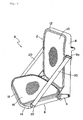
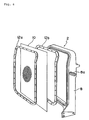
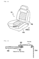
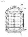
- Fig. 1 depicts a seat S that employs a cushioning member having a net-shaped skin according to the present invention and includes a seat back 2 and a seat cushion 6 rotatably connected to the seat back 2 via a hinge 4.
- each of the seat back 2 and the seat cushion 6 is the cushioning member having a net-shaped skin according to the present invention.
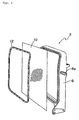
- the seat back 2 includes a seat back frame 8, a net-shaped skin 10 tensioned over the seat back frame 8, and a holding member 12 for holding the net-shaped skin 10 on the seat back frame 8.
- the seat back frame 8 has belt holes 8a, 8a (only one is shown in Fig. 2) defined therein on both sides thereof through which belts described later are drawn into the seat back frame 8.
- the seat cushion 6 includes a seat cushion frame 14, a net-shaped skin 16 tensioned over the seat cushion frame 14, and a holding member 18 for holding the net-shaped skin 16 on the seat cushion frame 14.
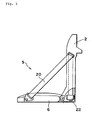
- the seat S also includes belts 20, 20 tensioned on both sides thereof, and each belt 20 has one end engaged with a belt anchor 22 rotatably mounted on the seat cushion frame 14 on one side thereof.
- the belt 20 is drawn to the inside of the seat back frame 8 through the belt hole 8a formed in the seat back frame 8.
- retractors 22, 22 are disposed inside the seat back frame 8 on both sides thereof in the vicinity of a lower end thereof, and the other ends of the belts 20, 20 are engaged with the retractors 22, 22, respectively.
- Figs. 1 and 3 depict the condition in which a man can sit on the seat with the belts 20, 20 completely drawn out of the retractors 22, 22, respectively.
- the seat is of a construction in which the load of a seat occupant applied to the seat back 2 is supported by the belts 20,20.
- the belts 20, 20 are retracted into the retractors 22, 22 to fold the seat cushion 6 towards the seat back 2.
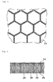
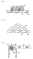
- Figs. 4 and 5 depict a three-dimensional mesh knit forming the net-shaped skins 10, 16.
- a fabric base is formed into a honeycomb-shaped (hexagonal) mesh.
- the mesh knit is of a three-layered solid truss structure in which an upper mesh layer 24 and a lower mesh layer 26 are connected to each other by a pile layer having a large number of piles 28.
- Each yarn of the upper mesh layer 24 and the lower mesh layer 26 is formed by twisting a number of fine threads, while each of the piles 28 is formed of a single thick string to provide the three-dimensional mesh knit with rigidity.
- Table 1 shows physical values of materials used for the upper mesh layer 24, the lower mesh layer 26, and the piles 28 forming the pile layer.
- Character d represents a denier
- 1d is a unit of thickness when 1 gram of thread has been pulled by 9,000 meters.
- Character f represents a filament that is a unit indicating the number of fine threads forming a yam
- 60f means that a yarn is made of 60 fine threads.
- the pulling strength "kg/5cm” is a strength when a mesh having a width of 5 cm has been pulled in the longitudinal direction.
- straight in the pile texture means that hexagons of the upper mesh layer 24 and those of the lower mesh layer 26 completely overlap each other as viewed from above, while “cross” means that they deviate from each other.
- Thermoplastic resins are preferably used as the material of the three-dimensional mesh knit, and it is sufficient if the material can be formed into fibers. When textiles are made of such material, it is sufficient if it provides a strength required for a sheet stock.
- thermoplastic polyester resins such as polyethylene terephthalate (PET), polybutylene terephthalate (PBT), etc., polyamide resins such as nylon 6, nylon 66, etc., polyolefin resins such as polyethylene, polypropylene, etc., and resins in which more than two kinds of such resins are mixed.
- each pile 28 is greater than 380d and, preferably, greater than 600d so that the load of a seat occupant applied to the three-dimensional mesh knit can be supported by deformation of the hexagonal meshes and by inclination of the piles, thereby providing a soft structure that causes no stress concentration.
- the net-shaped skin 10 is placed between the seat back frame 8 and the holding member 12 and is joined thereto by vibration welding.
- the holding member 12 is not always required, and the seat back frame 8 and the net-shaped skin 10 can be directly joined together by vibration welding.
- the vibration welding makes use of frictional heat to fuse thermoplastic resins.
- the frictional heat is produced by pressing two parts to be welded to each other and by simultaneously imparting vibration of a several-millimeter width to the welding surface.
- the vibration is stopped after a lapse of two or three seconds, the two parts automatically return to their original positions without any positional deviations, and subsequent about 1-second cooling results in high-strength welding.
- the vibration welding has the advantages of short cycle, low power consumption and no smell, and is applicable to complicated or irregular configurations. In addition, the positioning between parts is possible and the welding of a number of parts at one time is also easily possible. Moreover, the vibration welding enables welding of different materials and is also characterized by high-strength welding irrespective of water absorption properties and hardness.
- the vibration welding is generally utilized to join plate-like members together, but is utilized, in the practice of the present invention, to join by fusing fibers into a plate-like member.
- the seat back frame 8 is made of a metal such as iron.
- the net-shaped skin 10 is placed between the holding members 12a, 12b and joined thereto by vibration welding, and is subsequently screwed to the metal seat back frame 8.
- the use of the metal seat back frame 8 increases the rigidity of the seat back, which is therefore applicable to an automotive seat or the like to which an impact load is applied. If the net-shaped skin 10 becomes unusable, it is advantageous in that the holding members 12a, 12b and the net-shaped skin 10 can be replaced together.
- the net-shaped skin 10 after the net-shaped skin 10 has been joined to any one of the holding members 12a, 12b by vibration welding, it can be screwed to the metal seat back frame 8. In this case, of the holding members 12a, 12b, the one to which the net-shaped skin 10 has not been joined can be removed.
- Figs. 7 to 9 depict the second joining method.
- an edge treatment is carried out by passing a string (or a thread) 30 through edge portions of the upper mesh layer 24 and the lower mesh layer 26 of the net-shaped skin 10 at predetermined intervals to fix the net-shaped skin 10 to the holding member 12. Thereafter, as shown in Fig. 9, the holding member 12 is secured to the seat back frame 8 by means of bolts 32 and nuts 34. Head portions of the bolts 32 are covered with, for example, a resinous cover 36.
- the string 30 is not always passed through both the upper mesh layer 24 and the lower mesh layer 26, and may be passed through only one of them.
- Figs. 10 and 11 depict the third joining method.
- a resinous frame 12c is first formed along the circumference of the net-shaped skin 10 by insert molding, and is subsequently secured to the seat back frame by means of screws 38.
- Fig. 12 depicts a load-deflection curve of a three-dimensional mesh knit employed in the net-shaped skins 10, 16.
- This curve is a curve obtained by cutting off the three-dimensional mesh knit so as to have a circumferential length of 653 mm and by pressing a ⁇ 76-plate against it.
- This curve is a smooth non-linear curve compared with a curve of elastic material such as urethane. Because the three-dimensional mesh knit has a large hysteresis, when it is employed in an automotive seat, it can absorb external vibration energy effectively.
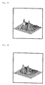
- Figs. 13 to 16 show body pressure distributions when a subject has sat on a conventional seat cushion and on a seat cushion employing a cushioning member according to the present invention.
- Figs. 13 and 14 show the body pressure distributions when a subject weighing 37 kg has sat on the conventional seat cushion and on the seat cushion employing the cushioning member according to the present invention, respectively, while
- Figs. 15 and 16 show the body pressure distributions when a subject weighing 93 kg has sat on the conventional seat cushion and on the seat cushion employing the cushioning member according to the present invention.
- urethane pads are partially fitted to a warp- and weft-knitted fabric in the form of a belt at positions where a feeling of foreign substances is sensed or the support pressure changes.
- the cushioning member of the present invention employing the three-dimensional mesh knit as the net-shaped skin includes the honeycomb-shaped upper and lower mesh layers 24, 26 and a large number of piles 28 each made of a single thick string, and is of a truss structure, it has the following advantages.
- the cushioning member having the net-shaped skin according to the present invention has the above-described features, when it is employed in, for example, a seat, it prevents hematogeous troubles around femoral regions, neuropathy, lumber troubles, etc., optimizes sweating or skin temperatures, and protects muscular tissues.
- the cushioning member having the net-shaped skin according to the present invention is employed in both the seat cushion and the seat back, it may be employed in only one of them. Also, the cushioning member of the present invention can be employed in a head rest mounted on the seat back, a bed, or the like.
- the cushioning member of the present invention is soft to sit on and has a soft spring constant in a region to be normally used, it does not easily transmit vibration even if it is thin and has a high rigidity. Accordingly, the cushioning member of the present invention can be employed in an automotive seat and also in a seat for a motorcycle because it is of the all-weather type.
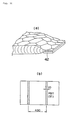
- Fig. 17 schematically depicts several fabric base textures used for the upper and lower mesh layers 24, 26, (a) depicting a honeycomb-shaped (hexagonal) mesh shown in Fig. 4, (b) depicting a diamond-shaped mesh, and (c) depicting a chain-inserted texture.
- Fig. 18 schematically depicts pile textures connecting the upper and lower mesh layers 24, 26, (a) depicting a generally straight texture corresponding to Fig. 5, (b) depicting a generally straight texture in the form of a figure "8", (c) depicting a cross texture, and (d) depicting a cross texture in the form of a figure "8".
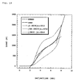
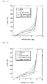
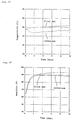
- Figs. 19 and 20 are graphs each showing static characteristics when a disc ( ⁇ 200) has been pressed against the cushioning member having the net-shaped skin according to the present invention.
- the fabric base texture of the honeycomb-shaped mesh shown in Fig. 17(a) is employed in the upper mesh layer 24, while the fabric base texture of the chain-inserted texture shown in Fig. 17(c) is employed in the lower mesh layer 26.
- the pile texture includes the generally straight texture of Fig. 18(a) as viewed in one direction and the cross texture of Fig. 18(c) as viewed in a direction perpendicular to said one direction. Items 09002D and D90028-5 (details thereof are described later) are used for the net-shaped skin.
- k3>k1>k2 where k1 is a spring constant in a small-load region, k2 a spring constant in a normal use region around a balanced point, and k3 a spring constant in a large-load region.
- the spring constant in the normal use region can be set to the smallest one.
- Table 2 shows physical values of the material used for the upper mesh layer 24, the lower mesh layer 26 and the piles 28 forming the pile layer, and those of other various materials.
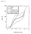
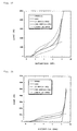
- Fig. 21 shows static characteristics when the net-shaped skin showing the static characteristics of Fig. 19 and the net-shaped skin showing the static characteristics of Fig. 20.have been laminated.
- the lamination reduces the spring constant as a whole and, hence, the spring constant can be freely controlled by increasing the number of lamination. Also, the stroke to a bottom end increases, and the load applied to each of the piles reduces, thereby reducing the bottom-end shock.
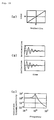
- Graphs shown in Figs. 22 to 24 schematize a relationship among load-deflection characteristics, transient response characteristics, and frequency response characteristics.
- the transient response and the frequency response of a non-linear spring system of Figs. 23 and 24 are improved as compared with those of a linear spring system of Fig. 22.
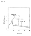
- Fig. 25 is a graph showing dynamic characteristics when a random wave has been inputted to a seat having a net-shaped skin according to the present invention and to a conventional seat employing urethane (thickness: 50 mm). There are little differences as a whole in the dynamic characteristics.
- Fig. 26 depicts a net-shaped skin into which rigid members 40 such as wires have been so inserted as to form a rectangle to enhance the spring action. Removal of the rigid members 40 is prevented by welding the piles positioned on both sides of each rigid member 40.
- Fig. 27 is a graph showing static characteristics when a disc ( ⁇ 200) has been pressed against a net-shaped skin of item 09001 D shown in Table 2, while Figs. 28 and 29 are graphs showing static characteristics when wires ( ⁇ 6) have been inserted as the rigid members 40.
- the terms “Large” and “Small” mean the interval between the wires to be inserted, as shown in Fig. 26(a).
- the spring constant becomes large as a whole, and an increased surface rigidity increases the region resistant to load and reduces the bottom-end shock. If elastic members are used in place of the rigid members, the elasticity thereof can be utilized.
- Fig. 30 depicts a cushioning member having a net-shaped skin to which resinous elastic members 42 such as PBT (polybutylene terephthalate) have been vibration-welded at two positions at a predetermined interval.
- Fig. 31 is a graph showing static characteristics when a disc ( ⁇ 200) has been pressed against such a cushioning member.
- the vibration welding of the resinous members increases the spring constant in the normal use region, enlarges the range of the normal use region, and reduces the bottom-end shock, as in the case in which the rigid members have been inserted in the form of a rectangle.
- Fig. 32 depicts a seat S1 in which the net-shaped skin according to the present invention is employed in a seat cushion 44 and in a seat back 46.
- the net-shaped skin 48 is vibration-welded at its periphery to elastic members 50, and the periphery of the net-shaped skin 48 and the elastic members 50 are both joined to a patch or trim 52 by sewing.
- the trim 52 is further joined to a side skin 54 by sewing.
- Resins such as polypropylene or the like, wadding (hard pads), fabric bases, etc. are preferably used for the elastic members 50.
- the net-shaped skin 48 is joined at its periphery to the engageable members 56 by vibration welding for the fixing thereof to a portion 58 of a frame.
- vibration welding for the fixing thereof to a portion 58 of a frame.
- the engageable members 56 may be engaged with a fitting 62 of the frame.
- rigid members 50 vibration-welded to the periphery of the net-shaped skin may be first inserted into the fitting 62, which can be in turn secured to the frame, as shown in Fig. 36, thereby imparting a desired tension to the net-shaped skin without using any tensioning jig.
- the engageable members 56 may be sewn and vibration-welded to only the lower mesh layer 26 of the net-shaped skin and, under the condition in which only sewn portions of the pile layer 28 that connects the upper and lower mesh layers 24, 26 are compressed, the periphery of the net-shaped skin may be joined to one end of a side skin 60 by sewing.
- the other end of the side skin 60 is sewn and vibration-welded to the rigid members 50, which are in turn engaged with the fitting 62 of the frame together with the engageable members 56.
- the lower mesh layer 26 and the engageable members 56 may be joined together by extrusion-molding or injection-molding the engageable members 56 to end portions of the lower mesh layer 26.
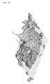
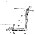
- a seat in which a plurality of net-shaped skins according to the present invention are laminated is discussed hereinafter with reference to Figs. 40 to 43.
- a seat S2 shown in Figs. 40 to 42 includes a seat cushion 66 having a plurality of net-shaped skins laminated on pipe frames 64 and a seat back 68 similarly having a plurality of laminated net-shaped skins.
- each of the seat cushion 66 and the seat back 68 employs the plurality of net-shaped skins as the first layer 70, the second layer 72, the third layer 74, the fourth layer 76, the fifth layer 78, and the sixth layer 80, all of which are laminated one above the other in this order.
- the rigid members 40 as shown in Fig. 26 are inserted into the net-shaped skin 80 of the sixth layer.
- Any one of the second to sixth layers 72-80 may be an urethane layer.
- a thin urethane layer causes a bottom-end shock and, hence, a spring structure is normally imparted thereto or a highly elastic urethane is combined therewith.
- a structure makes a cushion thick as a whole, a combination of the nets and urethane makes the cushion thinner than the conventional one and can cope with the bottom-end shock.
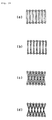
- a plurality of (five in Fig. 42) rolled net-shaped skins 82 may be arranged in a side-by-side fashion in place of the second to fifth layers 72-78 shown in Fig. 43.
- the structure in which the plurality of net-shaped skins are laminated as shown in Fig. 43 or in which the rolled net-shaped skins are juxtaposed as shown in Fig. 44 can reduce the bottom-end shock that is received by a user on a seat and reduces a spring constant to thereby improve the vibration characteristics around the resonant points. It is possible to further improve the vibration characteristics around the resonant points by incorporating a different kind of material such as a damping material, viscoelastic urethane, highly elastic urethane, low-repulsive urethane or the like. It is also possible to make a seat comfortable or soft to sit on and have a relatively large stroke, thereby enhancing an initial feeling.
- Figs. 45 and 46 show the body pressure distributions (subject weight: 50 kg) when no wires have been inserted into the honeycomb-shaped upper and lower mesh layers 24, 26 and when wires have been inserted as shown in Fig. 26 (wire interval: large), respectively.
- Figs. 47 and 48 similarly show the body pressure distributions (subject weight: 50 kg) when no wires have been inserted into the honeycomb-shaped upper and lower mesh layers 24, 26 and when wires have been inserted as shown in Fig. 26 (wire interval: small), respectively.
- the surface rigidity of the cushioning member having the net-shaped skin is increased by inserting the wires, and the increased surface rigidity disperses the body pressure to thereby reduce the local pressure.
- Figs. 49 and 50 show body pressure distributions (subject weight: 50 kg) when the subject has sat on a laminated structure of the net-shaped skin showing the static characteristics of Fig. 19 and the net-shaped skin showing the static characteristics of Fig. 20 with no resinous members vibration-welded thereto and when the subject has sat on another laminated structure in which the resinous members have been vibration-welded thereto (only the lower layer), as shown in Fig. 30, respectively.
- the vibration welding of the resinous members makes each pile forming the pile layer resistant to deflection, which disperses the body pressure, thereby reducing the local pressure.
- the elasticity of the cushioning member can be improved as a whole by making use of the elasticity of the resinous members, contributing to a reduction of the bottom-end shock.
- Figs. 51 and 52 show body pressure distributions (subject weight: 50 kg) when the subject has sat on a conventional seat employing urethane as a cushioning material and when he has sat on a wheelchair employing the laminated structure shown in Fig. 43, respectively.
- the laminated structure of the cushioning member according to the present invention effectively disperses the body pressure and reduces the local pressure.
- Figs. 53 and 54 show body pressure distributions (subject weight: 74 kg) when another subject has sat on a conventional wheelchair and when he has sat on the wheelchair employing the laminated structure shown in Fig. 43, respectively.
- the laminated structure of the cushioning member according to the present invention effectively disperses the body pressure and reduces the local pressure irrespective of the subject weight.
- Temperature and humidity characteristics are discussed hereinafter when a subject has sat on the conventional wheelchair and when he sat on the wheelchair having the laminated structure of the cushioning member according to the present invention.
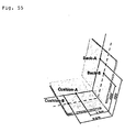
- Fig. 55 shows several check points where temperature and humidity characteristics have been examined.
- Figs. 56 and 57 show the characteristics at point Cushion-A when the subject is a great sweater
- Figs. 58 and 59 show the characteristics at point Back-A when the subject is an average man (not a great sweater).
- the temperature and humidity of the atmosphere were 35°C and 65%, respectively.
- the wheelchair according to the present invention is excellent in air permeability and heat dissipation properties, the temperature characteristics and the humidity characteristics are both improved as compared with the conventional wheelchair.
- the present invention provides the following effects.
- a cushioning member according to the present invention includes a net-shaped skin tensioned over a frame, the air permeability is enhanced, and a seat or bed can be reduced in weight by incorporating the cushioning member thereinto. Also, because the net-shaped skin is of a three-layered structure including an upper mesh layer, a lower mesh layer, and a pile layer having a large number of piles that connect the upper and lower mesh layers, and because each of the piles is made of a single string, the cushioning member has desired cushioning characteristics by the action of the elasticity of each pile.
- both the frame and the net-shaped skin are both made of a thermoplastic resin and joined together by vibration welding, they can be easily and strongly joined within a short period of time without lowering the physical properties of threads or strings of the net-shaped skin. Also, because both the frame and the net-shaped skin are made of a thermoplastic resin, it is possible to make all-weather seats that can be employed in motorcycles exposed to rainwater or the like.
- the holding member can be secured to a metal frame, which can be incorporated into an automotive seat that may receive an impact load. If the net-shaped skin is damaged, the skin and the holding member can be replaced together.
- an optional material can be used for the holding member or the frame.
- a resinous frame member is formed at the periphery of the net-shaped skin by insert molding and is secured to the above frame, a metal frame can be employed which can be incorporated into an automotive seat. In this case, if the net-shaped skin is damaged, the skin and the resinous frame member can be replaced together.
- the pile layer has a cross texture as viewed in a specific direction, there is no directional property of inclination of piles, enhancing the rigidity and allowing the sewing.
- the net-shaped skin has non-linear static load-deflection characteristics and also has the smallest spring constant in a normal use region including a balanced point, the transient response characteristics and the frequency response characteristics can be both improved. That is, the acceleration and deflection are attenuated quickly with respect to input changes and, hence, the period of time to the steady state can be shortened.
- the surface rigidity or the entire rigidity of the net-shaped skin can be increased, thereby reducing a bottom-end shock.
- the engageable members when the engageable members are attached at the periphery of the lower mesh layer and engaged with a portion of a seat under the condition in which the pile layer other than the sewn portions is not compressed, no feeling of foreign substances is sensed at the periphery of the net-shaped skin.
- the engageable members can be readily attached at the periphery of the lower mesh layer by extrusion-molding or injection-molding.
- the seat can be made thin, reduces a bottom-end shock, and improves vibration characteristics around the balanced point, as compared with conventional structures.
Landscapes
- Engineering & Computer Science (AREA)
- Textile Engineering (AREA)
- Seats For Vehicles (AREA)
- Mattresses And Other Support Structures For Chairs And Beds (AREA)
- Laminated Bodies (AREA)
Claims (14)
- Un élément de rembourrage ayant une armature et un revêtement rétifié (10, 16, 48, 70) tendu par-dessus l'armature,
caractérisé en ce que
le revêtement rétifié (10, 16, 48, 70) comprend une couche supérieure (24), une couche inférieure (26), et une couche de poils comportant un grand nombre de poils (28) qui relient les couches supérieure et inférieure (24, 26), chacun des poils (28) étant constitué d'une seule ficelle. - L'élément de rembourrage selon la revendication 1, dans lequel l'armature (12, 12a, 12b, 18) et le revêtement rétifié (10, 16, 48, 70) sont chacun en résine thermoplastique, et sont tous deux réunis ensemble par soudage par friction vibratoire.
- L'élément de rembourrage selon la revendication 1, dans lequel l'armature (8, 14) est en métal, tandis que le revêtement rétifié (10, 16, 48, 70) est en résine thermoplastique, et dans lequel, après que le revêtement rétifié (10, 16, 48, 70) a été réuni à au moins un élément de soutien (12, 12a, 12b, 18) fait en une résine thermoplastique, l'élément de soutien (12, 12a, 12b, 18) est fixé solidement à l'armature (8, 14).
- L'élément de rembourrage selon la revendication 1, dans lequel après que le revêtement rétifié (10, 16, 48, 70) a été solidement fixé en sa périphérie à un élément de soutien (12, 12a, 12b, 18) par une ficelle, l'élément de soutien (12, 12a, 12b, 18) est fixé solidement à l'armature (8, 14).
- L'élément de rembourrage selon la revendication 1, dans lequel une armature en résine (12c) est formée à une périphérie du revêtement rétifié (10, 16, 48, 70) par moulage d'insertion, et l'armature en résine (12c) est fixée solidement à l'armature (8, 14).
- L'élément de rembourrage selon la revendication 1, dans lequel la couche de poils présente une texture croisée lorsque vue dans une direction prédéterminée.
- L'élément de rembourrage selon la revendication 6, dans lequel l'élément de rembourrage (10, 16, 48, 70) a une caractéristique statique non linéaire de charge-déflexion et présente également au moins trois constantes de ressort dans une région normale d'utilisation, dans une région de charge inférieure à la région normale d'utilisation, et dans une région de charge supérieure à la région normale d'utilisation, et dans lequel la constante de ressort dans la région normale d'utilisation est réglée comme étant la plus faible.
- L'élément de rembourrage selon la revendication 6, comprenant en outre des éléments rigides ou éléments élastiques (40, 42) placés à intervalles prédéterminés dans au moins une certaine direction, ce qui augmente la rigidité de surface ou l'élasticité de la couche de mailles supérieure (24).
- L'élément de rembourrage selon la revendication 6, comprenant en outre des éléments à accoupler (56) montés sur une périphérie du revêtement rétifié (10, 15, 48, 70) par soudage par friction vibratoire, dans lequel les éléments à accoupler (56) sont montés sur une partie (58, 62) d'un siège.
- L'élément de rembourrage selon la revendication 6, comprenant en outre des éléments à accoupler (56) montés sur une périphérie de la couche inférieure (26), dans lequel les éléments à accoupler (56) sont montés sur une partie (62) d'un siège, la couche de poils n'étant pas comprimée.
- L'élément de rembourrage selon la revendication 10, dans lequel les éléments à accoupler (56) sont montés sur la périphérie de la couche inférieure (26) par moulage par extrusion.
- Un siège comprenant un coussin de siège (6) et un dossier de siège (2) caractérisé en ce qu'au moins l'un du coussin de siège (6) et du dossier de siège (2) comprend une armature et un revêtement rétifié (10, 16, 48, 70) selon l'une des revendications précédentes tendu par-dessus l'armature.
- Le siège selon la revendication 12, comprenant en outre une pluralité de revêtements rétifiés (72, 74, 76, 78, 80) selon l'une des revendications 1 à 11 stratifiés les uns sur les autres.
- Le siège selon la revendication 12, comprenant en outre une pluralité de revêtements rétifiés roulés (82) selon l'une des revendications 1 à 11 placés côte à côte.
Applications Claiming Priority (3)
| Application Number | Priority Date | Filing Date | Title |
|---|---|---|---|
| JP28879697 | 1997-10-21 | ||
| JP28879697 | 1997-10-21 | ||
| PCT/JP1998/004760 WO1999020159A1 (fr) | 1997-10-21 | 1998-10-21 | Coussin et siege comprenant chacun un revetement retifie |
Publications (3)
| Publication Number | Publication Date |
|---|---|
| EP1033098A1 EP1033098A1 (fr) | 2000-09-06 |
| EP1033098A4 EP1033098A4 (fr) | 2001-03-21 |
| EP1033098B1 true EP1033098B1 (fr) | 2004-03-17 |
Family
ID=17734851
Family Applications (1)
| Application Number | Title | Priority Date | Filing Date |
|---|---|---|---|
| EP98950319A Expired - Lifetime EP1033098B1 (fr) | 1997-10-21 | 1998-10-21 | Coussin et siege comprenant chacun un revetement retifie |
Country Status (8)
| Country | Link |
|---|---|
| US (1) | US6315364B1 (fr) |
| EP (1) | EP1033098B1 (fr) |
| KR (1) | KR100377117B1 (fr) |
| CN (1) | CN1124804C (fr) |
| AU (1) | AU9645098A (fr) |
| DE (1) | DE69822500T2 (fr) |
| TW (1) | TW381996B (fr) |
| WO (1) | WO1999020159A1 (fr) |
Families Citing this family (66)
| Publication number | Priority date | Publication date | Assignee | Title |
|---|---|---|---|---|
| JP2000325174A (ja) * | 1999-05-18 | 2000-11-28 | Delta Tooling Co Ltd | シート |
| JP4245232B2 (ja) * | 1999-07-21 | 2009-03-25 | 株式会社デルタツーリング | ネット材を用いた構造体、シート及びネット材の端末部処理方法 |
| JP2001087077A (ja) * | 1999-09-20 | 2001-04-03 | Delta Tooling Co Ltd | 3次元ネットを有するシート |
| JP4380896B2 (ja) * | 2000-08-02 | 2009-12-09 | 株式会社デルタツーリング | シート |
| JP4584403B2 (ja) * | 2000-04-13 | 2010-11-24 | 株式会社デルタツーリング | マット |
| CA2310349A1 (fr) * | 2000-05-22 | 2001-11-22 | Todd D. Krupiczewicz | Fauteuil de bureau |
| JP4666724B2 (ja) * | 2000-07-10 | 2011-04-06 | 株式会社デルタツーリング | 折り畳み式シート |
| US6540950B1 (en) | 2000-09-20 | 2003-04-01 | Dahti, Inc. | Carrier and attachment method for load bearing fabric |
| AU783829B2 (en) | 2000-09-28 | 2005-12-08 | Formway Furniture Limited | A reclinable chair |
| AUPR054400A0 (en) | 2000-09-29 | 2000-10-26 | Formway Furniture Limited | A castor |
| JP4484346B2 (ja) * | 2000-09-29 | 2010-06-16 | 株式会社デルタツーリング | 車両用シート |
| US20020096932A1 (en) * | 2000-10-02 | 2002-07-25 | Etsunori Fujita | Vehicle seat |
| HRP20000915B1 (en) | 2000-12-29 | 2008-06-30 | In�i� Su�anj Vladimir | Assembly of balls as an element of deck-chair, chair, back of a chair and arm-rest, and the process of assembling thereof |
| JP4832663B2 (ja) * | 2001-05-16 | 2011-12-07 | 株式会社デルタツーリング | クッション構造 |
| JP3592317B2 (ja) | 2001-07-04 | 2004-11-24 | 株式会社豊田中央研究所 | シート |
| JP4050511B2 (ja) * | 2001-12-20 | 2008-02-20 | 株式会社デルタツーリング | 座席構造 |
| US7124844B2 (en) * | 2002-06-14 | 2006-10-24 | Bombardier Recreational Products Inc. | Straddle-type mesh seat |
| WO2004008913A1 (fr) * | 2002-07-23 | 2004-01-29 | Okamura Corporation | Construction servant a fixer un filet a un siege ou a un bati de dossier |
| US10004342B2 (en) | 2002-12-17 | 2018-06-26 | Breathablebaby, Llc | Breathable toy |
| US10694868B2 (en) * | 2016-06-28 | 2020-06-30 | Breathablebaby, Llc | Layered crib shield system |
| US20170367496A1 (en) * | 2016-06-28 | 2017-12-28 | Breathablebaby, Llc | Durable crib shield system |
| US10722049B2 (en) * | 2016-06-28 | 2020-07-28 | Breathablebaby, Llc | Reversible crib shield system |
| US9872577B2 (en) | 2002-12-17 | 2018-01-23 | Breathablebaby, Llc | Breathable pillow |
| CA2633317C (fr) * | 2002-12-17 | 2009-05-26 | Breathablebaby, Llc | Systeme de protection de lit d'enfant et autre appareil permeable a l'air |
| US8793813B2 (en) | 2002-12-17 | 2014-08-05 | Breathablebaby, Llc | Breathable garment and method of use |
| US9370255B2 (en) | 2002-12-17 | 2016-06-21 | Breathablebaby, Llc | Crib shield system and other breathable apparatus |
| US9451835B2 (en) | 2002-12-17 | 2016-09-27 | Breathablebaby, Llc | Breathable playmat |
| US10588436B2 (en) | 2002-12-17 | 2020-03-17 | Breathablebaby, Llc | Breathable security blanket |
| US9247830B2 (en) | 2002-12-17 | 2016-02-02 | Breathablebaby, Llc | Breathable pillow |
| IL157632A0 (en) * | 2003-08-28 | 2004-03-28 | Keter Plastic Ltd | Furniture item and a method for attaching webbing thereto |
| US7376991B2 (en) * | 2004-10-01 | 2008-05-27 | Midmark Corporation | Medical examination table |
| WO2006094258A2 (fr) * | 2005-03-01 | 2006-09-08 | Haworth, Inc. | Dossier de fauteuil |
| GB0511393D0 (en) * | 2005-06-04 | 2005-07-13 | Space Net Technology Ltd | A seating system |
| US7461442B2 (en) * | 2005-06-10 | 2008-12-09 | Haworth, Inc. | Assembly apparatus and process for a chair back |
| US7395590B2 (en) * | 2005-06-10 | 2008-07-08 | Haworth, Inc. | Method for assembling a frame assembly for a chair |
| US20070200417A1 (en) * | 2005-11-19 | 2007-08-30 | York Julie L | Seat cushion using vertically lapped fiber |
| CN101351356A (zh) * | 2005-12-29 | 2009-01-21 | 哥瑞考儿童产品公司 | 汽车座椅 |
| US20070152488A1 (en) * | 2005-12-30 | 2007-07-05 | York Julie L | Arm rest using vertical lapped fiber |
| US7631941B2 (en) | 2006-03-15 | 2009-12-15 | Chang James L | Apparatus for supporting a person and method of forming thereof |
| US7484811B2 (en) * | 2006-03-15 | 2009-02-03 | Chang James L | Apparatus for supporting a person and method of forming thereof |
| EP2689693B1 (fr) * | 2007-09-20 | 2016-09-14 | Herman Miller, Inc. | Structure de support |
| JP5552491B2 (ja) | 2008-12-12 | 2014-07-16 | フォームウェイ ファーニチャー リミテッド | 椅子、支持体及びコンポーネント |
| US20110133531A1 (en) * | 2009-12-09 | 2011-06-09 | Yeh Chia-Chang | Seat applicable to vehicles |
| US8646134B1 (en) | 2011-06-22 | 2014-02-11 | Bedgear, Llc | Pillow with gusset of open cell construction |
| CN102578859B (zh) * | 2012-03-02 | 2014-11-05 | 明达实业(厦门)有限公司 | 一种充气产品的拉片结构及其制作方法 |
| CN102578860B (zh) * | 2012-03-02 | 2015-05-06 | 明达实业(厦门)有限公司 | 充气产品内腔拉片及其制作方法 |
| ES2538333T3 (es) | 2012-03-02 | 2015-06-19 | Intex Recreation Corporation | Producto inflable con un estructura de tensado interno |
| US9661930B2 (en) | 2012-09-21 | 2017-05-30 | Steelcase Inc. | Chair construction |
| US9155408B2 (en) | 2013-01-10 | 2015-10-13 | Bedgear, Llc | Pillow protector |
| US9149124B1 (en) * | 2013-04-04 | 2015-10-06 | Joseph Savovic | Engineered seating system for use in medical lift chairs |
| BE1022032B1 (nl) * | 2013-07-12 | 2016-02-05 | Advanced Spring Technology, Naamloze Vennootschap | Schuimconstructie en matras of kussen voorzien daarvan |
| EP3225764B1 (fr) | 2013-07-18 | 2020-09-09 | Intex Marketing Ltd. | Spa gonflable |
| CN103600502A (zh) | 2013-11-25 | 2014-02-26 | 明达实业(厦门)有限公司 | 一种充气产品熔着工艺 |
| US9463727B2 (en) * | 2014-08-14 | 2016-10-11 | Honda Motor Co., Ltd. | Vehicle seat covering assembly |
| CN110177489B (zh) * | 2016-09-15 | 2023-02-03 | 克兹二世有限公司 | 使用层状网材料的儿童支撑装置 |
| US10492624B2 (en) | 2017-09-15 | 2019-12-03 | Breathablebaby, Llc | Crib liner |
| US10472014B2 (en) * | 2018-01-12 | 2019-11-12 | Beto Engineering and Marketing Co., Ltd. | Baby seat of bicycle |
| CN111655080A (zh) * | 2018-01-31 | 2020-09-11 | 上海荣威塑胶工业有限公司 | 环绕式可充气床头板装置以及可充气床系统 |
| WO2019203653A1 (fr) * | 2018-04-19 | 2019-10-24 | Rm Brands As | Siège de camping pliant |
| CN109567476A (zh) * | 2018-11-26 | 2019-04-05 | 湖州中祺智能科技有限公司 | 一种具有弹性支撑功能的椅座垫 |
| EP3721848B1 (fr) * | 2019-04-12 | 2023-11-01 | Hill-Rom Services, Inc. | Ensemble de rétention de matelas et soudure par radiofréquence dans des couvertures de surface |
| DE202019107086U1 (de) * | 2019-12-18 | 2020-02-17 | Westfield Outdoors Gmbh | Sitzbezug für ein Sitzmöbel |
| CN111534029A (zh) * | 2020-05-15 | 2020-08-14 | 浙江大东方椅业股份有限公司 | 一种用于网椅背复合改性材料 |
| US11602225B2 (en) * | 2020-06-25 | 2023-03-14 | Haworth, Inc. | Knit seat back for an office chair |
| US11220196B1 (en) * | 2020-09-18 | 2022-01-11 | GM Global Technology Operations LLC | Multi-layer textile seat for dynamic conditions |
| DE102021117766A1 (de) | 2021-07-09 | 2023-01-12 | Audi Aktiengesellschaft | Sitzvorrichtung für ein Fahrzeug |
Family Cites Families (18)
| Publication number | Priority date | Publication date | Assignee | Title |
|---|---|---|---|---|
| JPS58144467A (ja) | 1982-02-22 | 1983-08-27 | Sumitomo Electric Ind Ltd | 被覆超硬合金工具 |
| JPS58144467U (ja) * | 1982-03-26 | 1983-09-29 | 日本発条株式会社 | シ−ト表皮の係止装置 |
| JPS6031864A (ja) | 1983-08-01 | 1985-02-18 | 井関農機株式会社 | 回転式穀物分離装置の穀粒撹散装置 |
| JPS6031864U (ja) * | 1983-08-09 | 1985-03-04 | 東和織物株式会社 | 夏用敷布団 |
| JPS6439052A (en) | 1987-08-05 | 1989-02-09 | Matsushita Electric Works Ltd | Pin grid array |
| JPS6439052U (fr) * | 1987-09-04 | 1989-03-08 | ||
| JPH01158761A (ja) | 1987-12-15 | 1989-06-21 | Fujitsu Ltd | 終端抵抗内蔵集積回路 |
| JPH01158761U (fr) * | 1988-04-22 | 1989-11-02 | ||
| JP2877866B2 (ja) | 1989-03-22 | 1999-04-05 | 二三産業株式会社 | スリーブ管取付方法 |
| JPH0747633Y2 (ja) * | 1989-06-29 | 1995-11-01 | 本田技研工業株式会社 | 巻掛伝動装置 |
| US5013089A (en) | 1989-09-15 | 1991-05-07 | General Motors Corporation | Thin profile integrated suspension and seat trim cover |
| JP3017352B2 (ja) | 1992-03-13 | 2000-03-06 | 富士通株式会社 | 監視制御システム及びそのシーケンス処理方式 |
| JP3208185B2 (ja) | 1992-08-27 | 2001-09-10 | 三洋電機株式会社 | 部品のリード位置認識方法及びそれを使用した部品装着装置 |
| US5378040A (en) * | 1993-01-22 | 1995-01-03 | Zoetech, Inc. | Adjustable geriatric chair |
| JPH0677699U (ja) * | 1993-04-16 | 1994-11-01 | 有限会社テック | 椅子の座部、背もたれ部における表装シートの装着構造 |
| US5393126A (en) * | 1993-06-21 | 1995-02-28 | Art Design International Inc. | Tubular frame seating structure with tension sleeve |
| US5533789A (en) * | 1994-11-10 | 1996-07-09 | Milliken Research Corporation | Seating structure |
| JPH0970339A (ja) * | 1995-07-05 | 1997-03-18 | Asahi Chem Ind Co Ltd | 床ずれ防止マット |
-
1998
- 1998-10-20 TW TW087117314A patent/TW381996B/zh not_active IP Right Cessation
- 1998-10-21 DE DE69822500T patent/DE69822500T2/de not_active Expired - Lifetime
- 1998-10-21 US US09/529,804 patent/US6315364B1/en not_active Expired - Lifetime
- 1998-10-21 EP EP98950319A patent/EP1033098B1/fr not_active Expired - Lifetime
- 1998-10-21 WO PCT/JP1998/004760 patent/WO1999020159A1/fr active IP Right Grant
- 1998-10-21 AU AU96450/98A patent/AU9645098A/en not_active Abandoned
- 1998-10-21 KR KR10-2000-7004340A patent/KR100377117B1/ko not_active IP Right Cessation
- 1998-10-21 CN CN98810329A patent/CN1124804C/zh not_active Expired - Fee Related
Also Published As
| Publication number | Publication date |
|---|---|
| AU9645098A (en) | 1999-05-10 |
| DE69822500T2 (de) | 2004-08-12 |
| EP1033098A1 (fr) | 2000-09-06 |
| CN1280467A (zh) | 2001-01-17 |
| WO1999020159A1 (fr) | 1999-04-29 |
| US6315364B1 (en) | 2001-11-13 |
| DE69822500D1 (de) | 2004-04-22 |
| EP1033098A4 (fr) | 2001-03-21 |
| CN1124804C (zh) | 2003-10-22 |
| KR100377117B1 (ko) | 2003-03-26 |
| TW381996B (en) | 2000-02-11 |
| KR20010031346A (ko) | 2001-04-16 |
Similar Documents
| Publication | Publication Date | Title |
|---|---|---|
| EP1033098B1 (fr) | Coussin et siege comprenant chacun un revetement retifie | |
| US7731294B2 (en) | Seat | |
| US6489000B1 (en) | Cushion having a three-dimensional net | |
| EP1733919B1 (fr) | Mécanisme de support d'une trame de base pour siège et structure du siège correspondant | |
| US7971939B2 (en) | Seat structure | |
| EP1084902B1 (fr) | Siège comportant un filet tridimensionnel | |
| US6435618B1 (en) | Seat | |
| KR100499757B1 (ko) | 좌석구조 | |
| US20020096932A1 (en) | Vehicle seat | |
| US20020060493A1 (en) | Vehicle seat | |
| JP2003182427A (ja) | 衝撃吸収構造及び座席構造 | |
| JP2002336076A (ja) | クッション構造 | |
| JP4741759B2 (ja) | シート用クッション構造 | |
| EP1023861A1 (fr) | Structure de coussin comportant un filet tridimensionnel | |
| JP2004188164A (ja) | 座席構造 | |
| JP4711663B2 (ja) | 座部用クッション材及びシート | |
| JP2003342859A (ja) | 立体編物及びシート構造 | |
| JP2005046355A (ja) | シート用面状支持部材 | |
| JP2002177091A (ja) | 乗物用シート | |
| JP2003306065A (ja) | シート |
Legal Events
| Date | Code | Title | Description |
|---|---|---|---|
| PUAI | Public reference made under article 153(3) epc to a published international application that has entered the european phase |
Free format text: ORIGINAL CODE: 0009012 |
|
| 17P | Request for examination filed |
Effective date: 20000522 |
|
| AK | Designated contracting states |
Kind code of ref document: A1 Designated state(s): DE FR GB |
|
| A4 | Supplementary search report drawn up and despatched |
Effective date: 20010206 |
|
| AK | Designated contracting states |
Kind code of ref document: A4 Designated state(s): DE FR GB |
|
| 17Q | First examination report despatched |
Effective date: 20020426 |
|
| RAP1 | Party data changed (applicant data changed or rights of an application transferred) |
Owner name: SUMINOE TEXTILE CO., LTD. Owner name: DELTA TOOLING CO., LTD. |
|
| GRAP | Despatch of communication of intention to grant a patent |
Free format text: ORIGINAL CODE: EPIDOSNIGR1 |
|
| GRAS | Grant fee paid |
Free format text: ORIGINAL CODE: EPIDOSNIGR3 |
|
| GRAA | (expected) grant |
Free format text: ORIGINAL CODE: 0009210 |
|
| AK | Designated contracting states |
Kind code of ref document: B1 Designated state(s): DE FR GB |
|
| REG | Reference to a national code |
Ref country code: GB Ref legal event code: FG4D |
|
| REF | Corresponds to: |
Ref document number: 69822500 Country of ref document: DE Date of ref document: 20040422 Kind code of ref document: P |
|
| ET | Fr: translation filed | ||
| PLBE | No opposition filed within time limit |
Free format text: ORIGINAL CODE: 0009261 |
|
| STAA | Information on the status of an ep patent application or granted ep patent |
Free format text: STATUS: NO OPPOSITION FILED WITHIN TIME LIMIT |
|
| 26N | No opposition filed |
Effective date: 20041220 |
|
| REG | Reference to a national code |
Ref country code: FR Ref legal event code: PLFP Year of fee payment: 19 |
|
| PGFP | Annual fee paid to national office [announced via postgrant information from national office to epo] |
Ref country code: FR Payment date: 20160913 Year of fee payment: 19 |
|
| PGFP | Annual fee paid to national office [announced via postgrant information from national office to epo] |
Ref country code: GB Payment date: 20161025 Year of fee payment: 19 Ref country code: DE Payment date: 20161103 Year of fee payment: 19 |
|
| REG | Reference to a national code |
Ref country code: DE Ref legal event code: R119 Ref document number: 69822500 Country of ref document: DE |
|
| GBPC | Gb: european patent ceased through non-payment of renewal fee |
Effective date: 20171021 |
|
| REG | Reference to a national code |
Ref country code: FR Ref legal event code: ST Effective date: 20180629 |
|
| PG25 | Lapsed in a contracting state [announced via postgrant information from national office to epo] |
Ref country code: GB Free format text: LAPSE BECAUSE OF NON-PAYMENT OF DUE FEES Effective date: 20171021 Ref country code: DE Free format text: LAPSE BECAUSE OF NON-PAYMENT OF DUE FEES Effective date: 20180501 |
|
| PG25 | Lapsed in a contracting state [announced via postgrant information from national office to epo] |
Ref country code: FR Free format text: LAPSE BECAUSE OF NON-PAYMENT OF DUE FEES Effective date: 20171031 |