EP1024484B1 - Procédé de fabrication d'un support d'enregistrement optique d'informations et support d'enregistrement optique d'informations - Google Patents
Procédé de fabrication d'un support d'enregistrement optique d'informations et support d'enregistrement optique d'informationsInfo
- Publication number
- EP1024484B1 EP1024484B1 EP00300336A EP00300336A EP1024484B1 EP 1024484 B1 EP1024484 B1 EP 1024484B1 EP 00300336 A EP00300336 A EP 00300336A EP 00300336 A EP00300336 A EP 00300336A EP 1024484 B1 EP1024484 B1 EP 1024484B1
- Authority
- EP
- European Patent Office
- Prior art keywords
- substrate
- solution
- application
- recording medium
- optical information
- Prior art date
- Legal status (The legal status is an assumption and is not a legal conclusion. Google has not performed a legal analysis and makes no representation as to the accuracy of the status listed.)
- Expired - Lifetime
Links
- 230000003287 optical effect Effects 0.000 title claims description 73
- 238000004519 manufacturing process Methods 0.000 title claims description 57
- 239000000758 substrate Substances 0.000 claims description 328
- 238000000034 method Methods 0.000 claims description 96
- 239000012530 fluid Substances 0.000 claims description 20
- 238000004378 air conditioning Methods 0.000 claims description 14
- 239000003960 organic solvent Substances 0.000 claims description 2
- 239000000243 solution Substances 0.000 description 224
- 239000000975 dye Substances 0.000 description 210
- 239000010410 layer Substances 0.000 description 79
- 230000007246 mechanism Effects 0.000 description 67
- 230000008569 process Effects 0.000 description 58
- 230000007723 transport mechanism Effects 0.000 description 42
- 230000000052 comparative effect Effects 0.000 description 23
- 239000011241 protective layer Substances 0.000 description 19
- 238000007689 inspection Methods 0.000 description 17
- 238000000465 moulding Methods 0.000 description 17
- 229920005989 resin Polymers 0.000 description 17
- 239000011347 resin Substances 0.000 description 17
- 230000003247 decreasing effect Effects 0.000 description 16
- 230000008859 change Effects 0.000 description 15
- 238000004544 sputter deposition Methods 0.000 description 13
- 230000007547 defect Effects 0.000 description 11
- 239000000463 material Substances 0.000 description 11
- 239000000126 substance Substances 0.000 description 11
- 238000000748 compression moulding Methods 0.000 description 10
- 150000002222 fluorine compounds Chemical class 0.000 description 10
- 238000002474 experimental method Methods 0.000 description 9
- 238000005406 washing Methods 0.000 description 9
- 239000004417 polycarbonate Substances 0.000 description 8
- 229920000515 polycarbonate Polymers 0.000 description 8
- 239000002904 solvent Substances 0.000 description 8
- 238000001816 cooling Methods 0.000 description 7
- 238000005192 partition Methods 0.000 description 7
- XLYOFNOQVPJJNP-UHFFFAOYSA-N water Substances O XLYOFNOQVPJJNP-UHFFFAOYSA-N 0.000 description 7
- 230000002950 deficient Effects 0.000 description 6
- 230000005611 electricity Effects 0.000 description 6
- 238000001746 injection moulding Methods 0.000 description 6
- -1 polytetrafluoroethylene Polymers 0.000 description 6
- 230000003068 static effect Effects 0.000 description 6
- 239000006185 dispersion Substances 0.000 description 5
- 238000002347 injection Methods 0.000 description 5
- 239000007924 injection Substances 0.000 description 5
- BDERNNFJNOPAEC-UHFFFAOYSA-N propan-1-ol Chemical compound CCCO BDERNNFJNOPAEC-UHFFFAOYSA-N 0.000 description 5
- RTZKZFJDLAIYFH-UHFFFAOYSA-N Diethyl ether Chemical compound CCOCC RTZKZFJDLAIYFH-UHFFFAOYSA-N 0.000 description 4
- LFQSCWFLJHTTHZ-UHFFFAOYSA-N Ethanol Chemical compound CCO LFQSCWFLJHTTHZ-UHFFFAOYSA-N 0.000 description 4
- 239000011230 binding agent Substances 0.000 description 4
- 239000003795 chemical substances by application Substances 0.000 description 4
- 150000001875 compounds Chemical class 0.000 description 4
- 238000001035 drying Methods 0.000 description 4
- VYPSYNLAJGMNEJ-UHFFFAOYSA-N silicon dioxide Inorganic materials O=[Si]=O VYPSYNLAJGMNEJ-UHFFFAOYSA-N 0.000 description 4
- 229910001220 stainless steel Inorganic materials 0.000 description 4
- 239000010935 stainless steel Substances 0.000 description 4
- ZWEHNKRNPOVVGH-UHFFFAOYSA-N 2-Butanone Chemical compound CCC(C)=O ZWEHNKRNPOVVGH-UHFFFAOYSA-N 0.000 description 3
- YMWUJEATGCHHMB-UHFFFAOYSA-N Dichloromethane Chemical compound ClCCl YMWUJEATGCHHMB-UHFFFAOYSA-N 0.000 description 3
- ZMXDDKWLCZADIW-UHFFFAOYSA-N N,N-Dimethylformamide Chemical compound CN(C)C=O ZMXDDKWLCZADIW-UHFFFAOYSA-N 0.000 description 3
- 229910052782 aluminium Inorganic materials 0.000 description 3
- 230000015572 biosynthetic process Effects 0.000 description 3
- 229910052804 chromium Inorganic materials 0.000 description 3
- 229910052681 coesite Inorganic materials 0.000 description 3
- 229920001577 copolymer Polymers 0.000 description 3
- 229910052906 cristobalite Inorganic materials 0.000 description 3
- 238000010586 diagram Methods 0.000 description 3
- 238000009826 distribution Methods 0.000 description 3
- 238000005562 fading Methods 0.000 description 3
- 229910052737 gold Inorganic materials 0.000 description 3
- 239000010931 gold Substances 0.000 description 3
- 229910052759 nickel Inorganic materials 0.000 description 3
- 229920003229 poly(methyl methacrylate) Polymers 0.000 description 3
- 239000004926 polymethyl methacrylate Substances 0.000 description 3
- 229920000915 polyvinyl chloride Polymers 0.000 description 3
- 239000004800 polyvinyl chloride Substances 0.000 description 3
- 238000011045 prefiltration Methods 0.000 description 3
- 229910052682 stishovite Inorganic materials 0.000 description 3
- 229920001187 thermosetting polymer Polymers 0.000 description 3
- ANRHNWWPFJCPAZ-UHFFFAOYSA-M thionine Chemical compound [Cl-].C1=CC(N)=CC2=[S+]C3=CC(N)=CC=C3N=C21 ANRHNWWPFJCPAZ-UHFFFAOYSA-M 0.000 description 3
- 229910052905 tridymite Inorganic materials 0.000 description 3
- 229920002554 vinyl polymer Polymers 0.000 description 3
- NWUYHJFMYQTDRP-UHFFFAOYSA-N 1,2-bis(ethenyl)benzene;1-ethenyl-2-ethylbenzene;styrene Chemical compound C=CC1=CC=CC=C1.CCC1=CC=CC=C1C=C.C=CC1=CC=CC=C1C=C NWUYHJFMYQTDRP-UHFFFAOYSA-N 0.000 description 2
- YELMWJNXDALKFE-UHFFFAOYSA-N 3h-imidazo[4,5-f]quinoxaline Chemical compound N1=CC=NC2=C(NC=N3)C3=CC=C21 YELMWJNXDALKFE-UHFFFAOYSA-N 0.000 description 2
- 239000004925 Acrylic resin Substances 0.000 description 2
- 229920000178 Acrylic resin Polymers 0.000 description 2
- HEDRZPFGACZZDS-UHFFFAOYSA-N Chloroform Chemical compound ClC(Cl)Cl HEDRZPFGACZZDS-UHFFFAOYSA-N 0.000 description 2
- YCKRFDGAMUMZLT-UHFFFAOYSA-N Fluorine atom Chemical compound [F] YCKRFDGAMUMZLT-UHFFFAOYSA-N 0.000 description 2
- KFZMGEQAYNKOFK-UHFFFAOYSA-N Isopropanol Chemical compound CC(C)O KFZMGEQAYNKOFK-UHFFFAOYSA-N 0.000 description 2
- LRHPLDYGYMQRHN-UHFFFAOYSA-N N-Butanol Chemical compound CCCCO LRHPLDYGYMQRHN-UHFFFAOYSA-N 0.000 description 2
- 239000004698 Polyethylene Substances 0.000 description 2
- 239000004743 Polypropylene Substances 0.000 description 2
- 239000004372 Polyvinyl alcohol Substances 0.000 description 2
- WYURNTSHIVDZCO-UHFFFAOYSA-N Tetrahydrofuran Chemical compound C1CCOC1 WYURNTSHIVDZCO-UHFFFAOYSA-N 0.000 description 2
- 239000006096 absorbing agent Substances 0.000 description 2
- 239000000654 additive Substances 0.000 description 2
- 239000000853 adhesive Substances 0.000 description 2
- 230000001070 adhesive effect Effects 0.000 description 2
- 229910045601 alloy Inorganic materials 0.000 description 2
- 239000000956 alloy Substances 0.000 description 2
- 239000003963 antioxidant agent Substances 0.000 description 2
- 230000003078 antioxidant effect Effects 0.000 description 2
- 239000012298 atmosphere Substances 0.000 description 2
- 238000005266 casting Methods 0.000 description 2
- 230000001276 controlling effect Effects 0.000 description 2
- 229910052802 copper Inorganic materials 0.000 description 2
- JHIVVAPYMSGYDF-UHFFFAOYSA-N cyclohexanone Chemical compound O=C1CCCCC1 JHIVVAPYMSGYDF-UHFFFAOYSA-N 0.000 description 2
- SWXVUIWOUIDPGS-UHFFFAOYSA-N diacetone alcohol Chemical compound CC(=O)CC(C)(C)O SWXVUIWOUIDPGS-UHFFFAOYSA-N 0.000 description 2
- 238000007599 discharging Methods 0.000 description 2
- 239000000428 dust Substances 0.000 description 2
- 229920001971 elastomer Polymers 0.000 description 2
- 239000003822 epoxy resin Substances 0.000 description 2
- 238000001125 extrusion Methods 0.000 description 2
- 229910052731 fluorine Inorganic materials 0.000 description 2
- 239000011737 fluorine Substances 0.000 description 2
- 238000010438 heat treatment Methods 0.000 description 2
- 230000008676 import Effects 0.000 description 2
- 239000003456 ion exchange resin Substances 0.000 description 2
- 229920003303 ion-exchange polymer Polymers 0.000 description 2
- 229910052751 metal Inorganic materials 0.000 description 2
- 239000002184 metal Substances 0.000 description 2
- 150000002832 nitroso derivatives Chemical class 0.000 description 2
- 239000001007 phthalocyanine dye Substances 0.000 description 2
- 229910052697 platinum Inorganic materials 0.000 description 2
- 229920000647 polyepoxide Polymers 0.000 description 2
- 229920000728 polyester Polymers 0.000 description 2
- 229920000573 polyethylene Polymers 0.000 description 2
- 229920000098 polyolefin Polymers 0.000 description 2
- 229920001343 polytetrafluoroethylene Polymers 0.000 description 2
- 239000004810 polytetrafluoroethylene Substances 0.000 description 2
- 229920002451 polyvinyl alcohol Polymers 0.000 description 2
- 238000007639 printing Methods 0.000 description 2
- 150000003839 salts Chemical class 0.000 description 2
- 229910052709 silver Inorganic materials 0.000 description 2
- 229920005992 thermoplastic resin Polymers 0.000 description 2
- XOLBLPGZBRYERU-UHFFFAOYSA-N tin dioxide Chemical compound O=[Sn]=O XOLBLPGZBRYERU-UHFFFAOYSA-N 0.000 description 2
- 238000009281 ultraviolet germicidal irradiation Methods 0.000 description 2
- WSLDOOZREJYCGB-UHFFFAOYSA-N 1,2-Dichloroethane Chemical compound ClCCCl WSLDOOZREJYCGB-UHFFFAOYSA-N 0.000 description 1
- RYHBNJHYFVUHQT-UHFFFAOYSA-N 1,4-Dioxane Chemical compound C1COCCO1 RYHBNJHYFVUHQT-UHFFFAOYSA-N 0.000 description 1
- QLCJOAMJPCOIDI-UHFFFAOYSA-N 1-(butoxymethoxy)butane Chemical compound CCCCOCOCCCC QLCJOAMJPCOIDI-UHFFFAOYSA-N 0.000 description 1
- ARXJGSRGQADJSQ-UHFFFAOYSA-N 1-methoxypropan-2-ol Chemical compound COCC(C)O ARXJGSRGQADJSQ-UHFFFAOYSA-N 0.000 description 1
- XNWFRZJHXBZDAG-UHFFFAOYSA-N 2-METHOXYETHANOL Chemical compound COCCO XNWFRZJHXBZDAG-UHFFFAOYSA-N 0.000 description 1
- ZNQVEEAIQZEUHB-UHFFFAOYSA-N 2-ethoxyethanol Chemical compound CCOCCO ZNQVEEAIQZEUHB-UHFFFAOYSA-N 0.000 description 1
- SVONRAPFKPVNKG-UHFFFAOYSA-N 2-ethoxyethyl acetate Chemical compound CCOCCOC(C)=O SVONRAPFKPVNKG-UHFFFAOYSA-N 0.000 description 1
- KXGFMDJXCMQABM-UHFFFAOYSA-N 2-methoxy-6-methylphenol Chemical compound [CH]OC1=CC=CC([CH])=C1O KXGFMDJXCMQABM-UHFFFAOYSA-N 0.000 description 1
- MUZDXNQOSGWMJJ-UHFFFAOYSA-N 2-methylprop-2-enoic acid;prop-2-enoic acid Chemical compound OC(=O)C=C.CC(=C)C(O)=O MUZDXNQOSGWMJJ-UHFFFAOYSA-N 0.000 description 1
- PYSRRFNXTXNWCD-UHFFFAOYSA-N 3-(2-phenylethenyl)furan-2,5-dione Chemical compound O=C1OC(=O)C(C=CC=2C=CC=CC=2)=C1 PYSRRFNXTXNWCD-UHFFFAOYSA-N 0.000 description 1
- ZYKBEIDPRRYKKQ-UHFFFAOYSA-N 4-[4-(diethylamino)-2-methylphenyl]imino-1-oxo-n-phenylnaphthalene-2-carboxamide Chemical compound CC1=CC(N(CC)CC)=CC=C1N=C1C2=CC=CC=C2C(=O)C(C(=O)NC=2C=CC=CC=2)=C1 ZYKBEIDPRRYKKQ-UHFFFAOYSA-N 0.000 description 1
- RSWGJHLUYNHPMX-UHFFFAOYSA-N Abietic-Saeure Natural products C12CCC(C(C)C)=CC2=CCC2C1(C)CCCC2(C)C(O)=O RSWGJHLUYNHPMX-UHFFFAOYSA-N 0.000 description 1
- DKPFZGUDAPQIHT-UHFFFAOYSA-N Butyl acetate Natural products CCCCOC(C)=O DKPFZGUDAPQIHT-UHFFFAOYSA-N 0.000 description 1
- 239000004215 Carbon black (E152) Substances 0.000 description 1
- 239000004709 Chlorinated polyethylene Substances 0.000 description 1
- XDTMQSROBMDMFD-UHFFFAOYSA-N Cyclohexane Chemical compound C1CCCCC1 XDTMQSROBMDMFD-UHFFFAOYSA-N 0.000 description 1
- 229920002307 Dextran Polymers 0.000 description 1
- 108010010803 Gelatin Proteins 0.000 description 1
- 239000013032 Hydrocarbon resin Substances 0.000 description 1
- NTIZESTWPVYFNL-UHFFFAOYSA-N Methyl isobutyl ketone Chemical compound CC(C)CC(C)=O NTIZESTWPVYFNL-UHFFFAOYSA-N 0.000 description 1
- UIHCLUNTQKBZGK-UHFFFAOYSA-N Methyl isobutyl ketone Natural products CCC(C)C(C)=O UIHCLUNTQKBZGK-UHFFFAOYSA-N 0.000 description 1
- CNCOEDDPFOAUMB-UHFFFAOYSA-N N-Methylolacrylamide Chemical compound OCNC(=O)C=C CNCOEDDPFOAUMB-UHFFFAOYSA-N 0.000 description 1
- 229930192627 Naphthoquinone Natural products 0.000 description 1
- 239000000020 Nitrocellulose Substances 0.000 description 1
- 229920002319 Poly(methyl acrylate) Polymers 0.000 description 1
- 239000004642 Polyimide Substances 0.000 description 1
- 229920002367 Polyisobutene Polymers 0.000 description 1
- 239000004793 Polystyrene Substances 0.000 description 1
- KHPCPRHQVVSZAH-HUOMCSJISA-N Rosin Natural products O(C/C=C/c1ccccc1)[C@H]1[C@H](O)[C@@H](O)[C@@H](O)[C@@H](CO)O1 KHPCPRHQVVSZAH-HUOMCSJISA-N 0.000 description 1
- 239000006087 Silane Coupling Agent Substances 0.000 description 1
- 229920000147 Styrene maleic anhydride Polymers 0.000 description 1
- BZHJMEDXRYGGRV-UHFFFAOYSA-N Vinyl chloride Chemical compound ClC=C BZHJMEDXRYGGRV-UHFFFAOYSA-N 0.000 description 1
- XAGFODPZIPBFFR-UHFFFAOYSA-N aluminium Chemical compound [Al] XAGFODPZIPBFFR-UHFFFAOYSA-N 0.000 description 1
- 150000001408 amides Chemical class 0.000 description 1
- 239000001000 anthraquinone dye Substances 0.000 description 1
- 239000002216 antistatic agent Substances 0.000 description 1
- 229910052797 bismuth Inorganic materials 0.000 description 1
- 229910052793 cadmium Inorganic materials 0.000 description 1
- 239000001913 cellulose Substances 0.000 description 1
- 229920002678 cellulose Polymers 0.000 description 1
- 150000008280 chlorinated hydrocarbons Chemical class 0.000 description 1
- 150000004696 coordination complex Chemical class 0.000 description 1
- 238000007791 dehumidification Methods 0.000 description 1
- 238000000151 deposition Methods 0.000 description 1
- 230000008021 deposition Effects 0.000 description 1
- 230000006866 deterioration Effects 0.000 description 1
- MTHSVFCYNBDYFN-UHFFFAOYSA-N diethylene glycol Chemical compound OCCOCCO MTHSVFCYNBDYFN-UHFFFAOYSA-N 0.000 description 1
- 238000004821 distillation Methods 0.000 description 1
- 150000002148 esters Chemical class 0.000 description 1
- 125000002573 ethenylidene group Chemical group [*]=C=C([H])[H] 0.000 description 1
- 239000005038 ethylene vinyl acetate Substances 0.000 description 1
- 229910052733 gallium Inorganic materials 0.000 description 1
- 239000008273 gelatin Substances 0.000 description 1
- 229920000159 gelatin Polymers 0.000 description 1
- 235000019322 gelatine Nutrition 0.000 description 1
- 235000011852 gelatine desserts Nutrition 0.000 description 1
- 229910052732 germanium Inorganic materials 0.000 description 1
- PCHJSUWPFVWCPO-UHFFFAOYSA-N gold Chemical compound [Au] PCHJSUWPFVWCPO-UHFFFAOYSA-N 0.000 description 1
- 229910052735 hafnium Inorganic materials 0.000 description 1
- FUZZWVXGSFPDMH-UHFFFAOYSA-N hexanoic acid Chemical compound CCCCCC(O)=O FUZZWVXGSFPDMH-UHFFFAOYSA-N 0.000 description 1
- 229930195733 hydrocarbon Natural products 0.000 description 1
- 229920006270 hydrocarbon resin Polymers 0.000 description 1
- 150000002430 hydrocarbons Chemical class 0.000 description 1
- 229920002681 hypalon Polymers 0.000 description 1
- 230000006872 improvement Effects 0.000 description 1
- 239000012535 impurity Substances 0.000 description 1
- 229910052738 indium Inorganic materials 0.000 description 1
- 239000001013 indophenol dye Substances 0.000 description 1
- 238000007733 ion plating Methods 0.000 description 1
- 229910052741 iridium Inorganic materials 0.000 description 1
- 229910052742 iron Inorganic materials 0.000 description 1
- 150000002576 ketones Chemical class 0.000 description 1
- 238000010030 laminating Methods 0.000 description 1
- 239000000314 lubricant Substances 0.000 description 1
- 229910001635 magnesium fluoride Inorganic materials 0.000 description 1
- 229910052748 manganese Inorganic materials 0.000 description 1
- DZVCFNFOPIZQKX-LTHRDKTGSA-M merocyanine Chemical compound [Na+].O=C1N(CCCC)C(=O)N(CCCC)C(=O)C1=C\C=C\C=C/1N(CCCS([O-])(=O)=O)C2=CC=CC=C2O\1 DZVCFNFOPIZQKX-LTHRDKTGSA-M 0.000 description 1
- 239000000434 metal complex dye Substances 0.000 description 1
- 229910052752 metalloid Inorganic materials 0.000 description 1
- 150000002738 metalloids Chemical class 0.000 description 1
- 229920003145 methacrylic acid copolymer Polymers 0.000 description 1
- 229940117841 methacrylic acid copolymer Drugs 0.000 description 1
- 238000002156 mixing Methods 0.000 description 1
- 239000003607 modifier Substances 0.000 description 1
- 229910052750 molybdenum Inorganic materials 0.000 description 1
- 150000002791 naphthoquinones Chemical class 0.000 description 1
- 229910052758 niobium Inorganic materials 0.000 description 1
- 229920001220 nitrocellulos Polymers 0.000 description 1
- 229910052763 palladium Inorganic materials 0.000 description 1
- 230000036961 partial effect Effects 0.000 description 1
- 229920001568 phenolic resin Polymers 0.000 description 1
- 229920003023 plastic Polymers 0.000 description 1
- 239000004033 plastic Substances 0.000 description 1
- 239000004014 plasticizer Substances 0.000 description 1
- 229920001200 poly(ethylene-vinyl acetate) Polymers 0.000 description 1
- 229920001721 polyimide Polymers 0.000 description 1
- 229920001155 polypropylene Polymers 0.000 description 1
- 229920000379 polypropylene carbonate Polymers 0.000 description 1
- 229920002223 polystyrene Polymers 0.000 description 1
- 239000011118 polyvinyl acetate Substances 0.000 description 1
- 229920002689 polyvinyl acetate Polymers 0.000 description 1
- 230000002035 prolonged effect Effects 0.000 description 1
- WVIICGIFSIBFOG-UHFFFAOYSA-N pyrylium Chemical compound C1=CC=[O+]C=C1 WVIICGIFSIBFOG-UHFFFAOYSA-N 0.000 description 1
- 230000009467 reduction Effects 0.000 description 1
- 230000002829 reductive effect Effects 0.000 description 1
- 230000001105 regulatory effect Effects 0.000 description 1
- 229910052702 rhenium Inorganic materials 0.000 description 1
- 229910052703 rhodium Inorganic materials 0.000 description 1
- 229910052707 ruthenium Inorganic materials 0.000 description 1
- 229910052710 silicon Inorganic materials 0.000 description 1
- 239000000377 silicon dioxide Substances 0.000 description 1
- LIVNPJMFVYWSIS-UHFFFAOYSA-N silicon monoxide Inorganic materials [Si-]#[O+] LIVNPJMFVYWSIS-UHFFFAOYSA-N 0.000 description 1
- 230000006641 stabilisation Effects 0.000 description 1
- 238000011105 stabilization Methods 0.000 description 1
- 229910052715 tantalum Inorganic materials 0.000 description 1
- YLQBMQCUIZJEEH-UHFFFAOYSA-N tetrahydrofuran Natural products C=1C=COC=1 YLQBMQCUIZJEEH-UHFFFAOYSA-N 0.000 description 1
- OKYDCMQQLGECPI-UHFFFAOYSA-N thiopyrylium Chemical compound C1=CC=[S+]C=C1 OKYDCMQQLGECPI-UHFFFAOYSA-N 0.000 description 1
- 229910052719 titanium Inorganic materials 0.000 description 1
- KHPCPRHQVVSZAH-UHFFFAOYSA-N trans-cinnamyl beta-D-glucopyranoside Natural products OC1C(O)C(O)C(CO)OC1OCC=CC1=CC=CC=C1 KHPCPRHQVVSZAH-UHFFFAOYSA-N 0.000 description 1
- AAAQKTZKLRYKHR-UHFFFAOYSA-N triphenylmethane Chemical compound C1=CC=CC=C1C(C=1C=CC=CC=1)C1=CC=CC=C1 AAAQKTZKLRYKHR-UHFFFAOYSA-N 0.000 description 1
- 229910052721 tungsten Inorganic materials 0.000 description 1
- 238000011144 upstream manufacturing Methods 0.000 description 1
- 229910052720 vanadium Inorganic materials 0.000 description 1
- 238000007740 vapor deposition Methods 0.000 description 1
- 238000009423 ventilation Methods 0.000 description 1
- 125000000391 vinyl group Chemical group [H]C([*])=C([H])[H] 0.000 description 1
- 229910052727 yttrium Inorganic materials 0.000 description 1
- 229910052725 zinc Inorganic materials 0.000 description 1
- 229910052726 zirconium Inorganic materials 0.000 description 1
Images











Classifications
-
- G—PHYSICS
- G11—INFORMATION STORAGE
- G11B—INFORMATION STORAGE BASED ON RELATIVE MOVEMENT BETWEEN RECORD CARRIER AND TRANSDUCER
- G11B7/00—Recording or reproducing by optical means, e.g. recording using a thermal beam of optical radiation by modifying optical properties or the physical structure, reproducing using an optical beam at lower power by sensing optical properties; Record carriers therefor
- G11B7/24—Record carriers characterised by shape, structure or physical properties, or by the selection of the material
-
- B—PERFORMING OPERATIONS; TRANSPORTING
- B05—SPRAYING OR ATOMISING IN GENERAL; APPLYING FLUENT MATERIALS TO SURFACES, IN GENERAL
- B05D—PROCESSES FOR APPLYING FLUENT MATERIALS TO SURFACES, IN GENERAL
- B05D1/00—Processes for applying liquids or other fluent materials
- B05D1/002—Processes for applying liquids or other fluent materials the substrate being rotated
- B05D1/005—Spin coating
-
- G—PHYSICS
- G11—INFORMATION STORAGE
- G11B—INFORMATION STORAGE BASED ON RELATIVE MOVEMENT BETWEEN RECORD CARRIER AND TRANSDUCER
- G11B7/00—Recording or reproducing by optical means, e.g. recording using a thermal beam of optical radiation by modifying optical properties or the physical structure, reproducing using an optical beam at lower power by sensing optical properties; Record carriers therefor
- G11B7/24—Record carriers characterised by shape, structure or physical properties, or by the selection of the material
- G11B7/26—Apparatus or processes specially adapted for the manufacture of record carriers
-
- Y—GENERAL TAGGING OF NEW TECHNOLOGICAL DEVELOPMENTS; GENERAL TAGGING OF CROSS-SECTIONAL TECHNOLOGIES SPANNING OVER SEVERAL SECTIONS OF THE IPC; TECHNICAL SUBJECTS COVERED BY FORMER USPC CROSS-REFERENCE ART COLLECTIONS [XRACs] AND DIGESTS
- Y10—TECHNICAL SUBJECTS COVERED BY FORMER USPC
- Y10S—TECHNICAL SUBJECTS COVERED BY FORMER USPC CROSS-REFERENCE ART COLLECTIONS [XRACs] AND DIGESTS
- Y10S428/00—Stock material or miscellaneous articles
- Y10S428/913—Material designed to be responsive to temperature, light, moisture
-
- Y—GENERAL TAGGING OF NEW TECHNOLOGICAL DEVELOPMENTS; GENERAL TAGGING OF CROSS-SECTIONAL TECHNOLOGIES SPANNING OVER SEVERAL SECTIONS OF THE IPC; TECHNICAL SUBJECTS COVERED BY FORMER USPC CROSS-REFERENCE ART COLLECTIONS [XRACs] AND DIGESTS
- Y10—TECHNICAL SUBJECTS COVERED BY FORMER USPC
- Y10T—TECHNICAL SUBJECTS COVERED BY FORMER US CLASSIFICATION
- Y10T428/00—Stock material or miscellaneous articles
- Y10T428/21—Circular sheet or circular blank
Definitions
- the optical information-recording medium of the CD-R type has a representative structure comprising a recording layer composed of an organic dye, a light-reflective layer composed of a metal such as gold, and a protective layer made of a resin which are stacked in this order on a transparent disk-shaped substrate having a thickness of about 1.2 mm (see, for example. Japanese Laid-Open Patent Publication No. 6-150371 ).
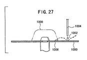
- a method is conceived, in which a mask 1008 is installed on a portion to which it is not intended to allow any droplet to adhere.
- the surface of the mask 1008 is stained by the droplets of the dye solution 1002.
- the stain is dried, it is scattered as dust. For this reason, it is feared that a new problem arises in that such a process may cause any defect.
- the present invention has been made taking the foregoing problems into consideration, an object of which is to provide a method for producing an optical information-recording medium, in which the occurrence of defective appearance is avoided by preventing scattering of a dye solution, and it is possible to improve the yield of the optical information-recording medium.
- the present invention has been made taking the foregoing problems into consideration, another object of which is to provide a method for producing an optical information-recording medium, in which the dispersion of the level of a push-pull signal in the radial direction can be decreased, the signal intensity of the push-pull signal can be within a prescribed range, and it is possible to produce the optical information-recording medium having a high quality.
- the timing, at which the number of revolutions of the substrate is increased is set immediately before the nozzle arrives at the innermost circumference. Specifically, the number of revolutions of the substrate is increased at a stage at which the nozzle arrives at a position which is separated from the innermost circumference of the substrate by a distance shorter than 20 mm, preferably at a stage at which the nozzle arrives at a position which is separated from the innermost circumference of the substrate by a distance shorter than 10 mm, and most preferably at a stage at which the nozzle arrives at a position which is separated from the innermost circumference of the substrate by a distance shorter than 5 mm.
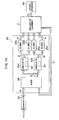
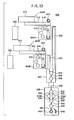
- Each of the first and second molding equipments 12A, 12B includes a molding machine 20 for performing injection molding, compression molding, or injection compression molding of a resin material such as polycarbonate to produce the substrate formed, on the first principal surface, with a tracking groove or irregularity (groove) to indicate information such as an address signal, a cooling section 22 for cooling the substrate taken out of the molding machine 20, and a stacking section 26 (stack pole rotary table) installed with a plurality of stack poles 24 for stacking and storing the substrates after being cooled.
- a molding machine 20 for performing injection molding, compression molding, or injection compression molding of a resin material such as polycarbonate to produce the substrate formed, on the first principal surface, with a tracking groove or irregularity (groove) to indicate information such as an address signal
- a cooling section 22 for cooling the substrate taken out of the molding machine 20
- a stacking section 26 stack pole rotary table
- the application equipment 14 comprises three process units 30, 32, 34.
- the first process unit 30 includes a stack pole-accommodating section 40 for accommodating the stack pole 24 transported from the first and second molding equipments 12A, 12B, a first transport mechanism 42 for extracting the substrate one by one from the stack pole 24 accommodated in the stack pole-accommodating section 40 to transport the substrate to the next step, and an electrostatic blow mechanism 44 for removing static electricity from one substrate transported by the first transport mechanism 42.
- the third process unit 34 comprises a back surface-washing mechanism 54 for washing the back surface of one substrate transported by the third transport mechanism 50, a fourth transport mechanism 56 for transporting, to the next step, the substrate completed for the back surface washing, a numbering mechanism 58 for stamping a lot number or the like on the substrate transported by the fourth transport mechanism 56, a fifth transport mechanism 60 for transporting, to the next step, the substrate completed for the stamping of the lot number or the like, an inspecting mechanism 62 for inspecting the presence or absence of defect and the film thickness of the dye recording layer of the substrate transported by the fifth transport mechanism 60, and a sorting mechanism 68 for sorting the substrates into those to be stacked on a stack pole 64 for normal products and those to be stacked on a stack pole 66 for NG depending on a result of inspection performed by the inspecting mechanism 62.
- the aftertreatment equipment 16 further includes a second electrostatic blow mechanism 94 for removing static electricity from the substrate completed for the edge washing, a UV-curable solution-applying mechanism 96 for applying a UV-curable solution to the first principal surface of the substrate completed for the electrostatic blow treatment, a spin mechanism 98 for rotating, at a high speed, the substrate completed for the application of the UV-curable solution to obtain a uniform thickness of the applied film the UV-curable solution on the substrate, a UV-radiating mechanism 100 for radiating ultraviolet light onto the substrate completed for the application of the UV-curable solution and the spin treatment so that the UV-curable solution is cured to form a protective layer on the first principal surface of the substrate, a ninth transport mechanism 102 for transporting the substrate to the second electrostatic blow mechanism 94, the UV-curable solution-applying mechanism 96, the spin mechanism 98, and the UV-radiating mechanism 100 respectively, a tenth transport mechanism 104 for transporting the substrate irradiated with UV to the next step, a
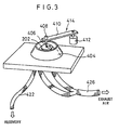
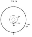
- the spin coat apparatus 52 comprises a solution supply apparatus 400, a spinner head apparatus 402, and a scattering-preventive wall 404.
- the solution supply apparatus 400 is arranged to be capable of making swinging movement from a waiting position to a position over the substrate 202 by the aid of a handling mechanism 414 comprising a support plate 410 for supporting the nozzle 406 directed downwardly and a motor 412 for swinging the support plate 410 in the horizontal direction.
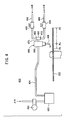
- the fluid which is introduced from the fluid supply line 458, is supplied to the main valve apparatus body 468 via the input port 466 and the output port 470 of the quick exhaust valve 456.
- the internal valve is operated in the opening direction in accordance with the increase in pressure in the main valve apparatus body 468 corresponding to the supply of the fluid. Therefore, the opening speed of the valve (change of opening degree of the valve per unit time) is proportional to the amount of supply of the fluid per unit time.
- the supply amount is adjustable depending on the opening degree of the first speed controller 462.
- the span of change (slope of characteristic curve) of the discharge amount depends on the closing speed of the valve at the stage in which the discharge amount is decreased proportionally.
- the span of change of the discharge amount is decreased as the closing speed is decreased.
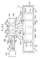
- the production system 10 is further installed with an air-conditioning system 300 in parallel to the second process unit 32 of the application equipment 14.
- an air conditioner 704 is installed on the ceiling of the first process unit 30 via a high performance packed bed filter (HEPA filter) 700.
- HEPA filter 702 is installed on the ceiling of the third process unit 34.
- the air-conditioning system 300 is provided with a duct 310 for feeding the primary air a1 outputted from the dehumidifier 304 to the air conditioner 302, the duct 310 being disposed between the dehumidifier 304 and the air conditioner 302.
- the exhaust tube 426 described above is provided between the exhaust apparatus 306 and each of the exhaust sides of the six spin coat apparatuses 52 of the dye application mechanism 48 of the application equipment 14.
- Those installed between the air conditioner 302 and the application equipment 14 are a plurality of (four in the embodiment illustrated in the drawing) air supply ducts 320a to 320d for feeding the clean air "ca" outputted from the air conditioner 302 to the application equipment 14, and a plurality of (eight in the embodiment illustrated in the drawing) return ducts 322 for returning the discharge air "ra” other than the local discharge air “da” from the application equipment 14 to the air conditioner 302.
- the air conditioner 302 comprises a mixer 330 for mixing the primary air a1 from the dehumidifier 304 or the inlet port 710 and the discharge air (discharge air other than the local discharge air) "ra" from the application equipment 14 to obtain the mixed air "ha” to be outputted, two humidifiers 332a, 332b for performing the humidifying treatment for the mixed air "ha” outputted from the mixer 330 to obtain the secondary air a2 to be outputted, and four blowers 334a to 334d for feeding, to the application equipment 14, the secondary air a2 from the two humidifiers 332a, 332b.
- Each of the humidifiers 332a, 332b includes, at its inside, a heating plate 336 for adding vaporized water to the primary air a1. Pure water is spread over the heating plate 336.
- the pure water used in this embodiment is appropriately pure water having a specific resistance of not less than 0.15 M ⁇ (room temperature). It is possible to use pure water preferably having a specific resistance of not less than 1.5 M ⁇ (room temperature), and more preferably having a specific resistance of not less than 15 M ⁇ (room temperature). In this embodiment, pure water having a specific resistance of 2 M ⁇ (room temperature) is used.
- HEPA filters high performance packed bed filters
- Directional control plates 342a to 342d are installed respectively between the four blowers 334a to 334d and the four respective corresponding air supply ducts 320a to 320d.
- Directional control plates 344a to 344d are installed respectively as well at upper portions of the application equipment 14 between the four air supply ducts 320a to 320d and the respective corresponding HEPA filters 340a to 340d.
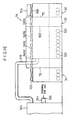
- the first partition plate 70 is provided between the first and second process units 30, 32
- the second partition plate 72 is provided between the second and third process units 32, 34. Therefore, there is neither inflow of air from the first process unit 30 to the second process unit 32 nor inflow of air from the third process unit 34 to the second process unit 32. Accordingly, it is possible to maintain a state in which the pressure in the atmosphere in the second process unit 32 is higher than the pressures in the respective atmospheres in the first and third process units 30, 34.
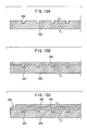
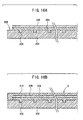
- the resin material such as polycarbonate is subjected to injection molding, compression molding, or injection compression molding by using the molding machine 20 of each of the first and second molding equipments 12A, 12B to produce the substrate 202 including the tracking groove or the irregularity (groove) 200 for indicating information such as an address signal, formed on the first principal surface as shown in FIG. 15A .
- the application of the dye solution is started.
- the nozzle 410 is moved once toward the inner circumferential side.
- the dye solution is applied, while the support plate 410 is rotated in the horizontal direction to move the nozzle 406 in about 3 seconds to a position of radius of 40 mm.
- the number of revolutions of the substrate 202 is increased to 550 rpm.
- the number of revolutions of the substrate 202 is increased in 6.3 seconds to 1400 rpm.
- Each of the first and second molding equipments 602A, 602B includes a molding machine 610 for performing injection molding, compression molding, or injection compression molding of a resin material such as polycarbonate to produce the substrate 202 formed, on the first principal surface, with a tracking groove or irregularity (groove) 200 to indicate information such as an address signal, and a cooling conveyer 612 for cooling the substrate 202 while transporting the substrate 202 taken out of the molding machine 610.
- Stack poles 614 for stacking and storing the substrates 202 after the cooling treatment are installed at the terminal end of the cooling conveyer 612.
- Each of the first and second application equipments 604A, 604B comprises three spin coat apparatuses 616 for applying the dye and washing the edge, and a multi-joint robot 618 for extracting one by one the substrate 202 stacked on the stack pole 614 for the first and second molding equipments 602A, 602B and transporting the substrate 202 to any one of the spin coat apparatuses 616.
- the inspection equipment 606 comprises a first transport conveyer 620 for transporting the substrate 202 completed for the treatment in the first application equipment 604A to the next step, a second transport conveyer 622 for transporting the substrate 202 completed for the treatment in the second application equipment 604B to the next step, a numbering mechanism 624 for stamping a lot number or the like on the substrate 202 transported by the first and second transport conveyers 620, 622, a first transport mechanism 626 for transporting, to the next step, the substrate 202 completed for the stamping of the lot number or the like, and an inspecting mechanism 628 for inspecting the presence or absence of defect and the film thickness of the dye recording layer 204 of the substrate 202 transported by the first transport mechanism 626.
- the substrate 202 is continuously transported after the film of the light-reflective layer 208 is formed so that the UV-curable solution for forming the protective layer is dripped onto the light-reflective layer 208.
- the substrates 202 subjected to the film formation of the light-reflective layer 208 may be once accumulated, and the UV-curable solution may be dripped onto the substrate 202, for example, by means of a sheet-feed procedure.
- the substrate 202 with the formed film of the light-reflective layer 208 may be stacked on a stack pole, and it may be transported, for example, to the subsequent UV-curable solution-applying step.
- the first illustrative experiment relates to samples (Examples 1 to 4 and Comparative Examples 1 to 3) when the optical disk D is produced by using the production system 10 shown in FIG. 1 , which is directed to the scattering probability, the time until the application speed is stabilized, and the application ratio when the opening degree of the first speed controller 462 is changed.
- a polycarbonate substrate (diameter: 120 mm, thickness: 1.2 mm) was prepared, in which a spiral-shaped groove (track pitch: 1.6 ⁇ m, groove width: 0.4 ⁇ m, groove depth: 0.16 ⁇ m) was formed on the surface by means of injection molding.
- the dye solution was applied by means of spin coat onto the surface on the side of the groove of the polycarbonate substrate while changing the number of revolutions from 270 rpm to 2000 rpm to form the dye recording layer 204 (thickness in the groove: about 200 nm).
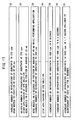
- the process for applying the dye solution was carried out in accordance with the steps shown in FIG. 17 .
- the pressure of the pressurizing tank was 0.3 kgf/cm 2 .
- the opening degree of the first speed controller 462 is 2 % which is lower than 5 %. Therefore, any non-applied portion appeared due to shortage of the discharge amount of the dye solution.
- the application ratio was 20 %.
- the light reflectance (%) indicates the light reflectance obtained when no pit is formed for the groove, i.e., in the non-recorded state. It is prescribed that the light reflectance during reproduction is not less than 65 % for the practical optical disk D. Therefore, it is sufficient that the light reflectance is not less than 67 % in the non-recorded state.
- the signal intensity of the push-pull signal is less than 0.09, the tracking deviation tends to occur. On the contrary, if the signal intensity of the push-pull signal is not less than 0.14, it is indicated that the light reflectance is too low.
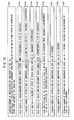
- the dye solution was applied in accordance with the following application patterns. That is, the application was carried out in accordance with the first process shown in FIG. 17 for Examples 5 to 7 and Comparative Example 4 (conveniently referred to as "Pattern A").
- Example 5 is illustrative of a case in which the number of revolutions of the substrate 202 was 270 rpm in the step S3 shown in FIG. 17 , i.e., the application was carried out without changing the number of revolutions of the substrate 202 (conveniently referred to as "Pattern B").
- the signal intensity of the push-pull signal is 0.15 at the position of radius of 23 mm, indicating that the light reflectance is insufficient.
- the measured light reflectance is 66 %, which does not satisfies the prescribed value of 67 %.
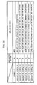
- Example 11 Comparative Examples 11 to 16 when the optical disk D (radius: 60 mm) is produced by using the production system 10 shown in FIG. 1 to observe the characteristic obtained when the application pattern is changed with respect to the applied surface shown in FIG. 18 . Obtained experimental results are shown in FIG. 25 .
- Example 11 at first, the substrate 202 was rotated at a number of revolutions of 200 rpm, simultaneously with which the application of the dye solution was started (see the step S101 in FIG. 18 ) at the stage at which the arm 410 (see FIG. 3 ) of the solution supply apparatus 400 arrived at a position of 55 mm from the center of the substrate 202. After that, the arm 410 was moved toward the inner circumferential side of the substrate 202 (see the step S102) at a speed of 30 mm/s while performing the application of the dye solution.
- the pressure for applying the dye solution by using the nozzle 406 was not more than 0.5 atm., and the application flow rate of the dye solution by using the nozzle was 0.2 cc/second.
- the number of revolutions of the substrate 202 was increased to 400 rpm (see the step S103) at the stage at which the nozzle 406 arrived at a position of 30 mm from the center of the substrate 202.
- the arm 410 was stopped for 0.2 second (see the step S104) at the stage at which the nozzle 406 arrived at a position of 20 mm from the center of the substrate 202 (innermost circumference).
- the arm 410 was moved toward the outer circumferential side of the substrate 202 at a speed of 60 mm/s (see the step S105).
- the application of the dye solution was stopped (see the step S106) at the stage at which the nozzle 406 arrived at a position of 30 mm from the center of the substrate 202.
- the arm 410 was rotated in the horizontal direction to restore the nozzle 406 to the original position (initial state).
- the series of application pattern is defined to be Pattern C.
- Comparative Example 11 was carried out in the same manner as Example 11 except that the application of the dye solution was started at a position of 40 mm from the center of the substrate 202 in the step S101. This application pattern is designated as Pattern D. Comparative Example 12 was carried out in the same manner as Example 11 except that the number of revolutions upon the start of application of the dye solution was 350 rpm. This application pattern is designated as Pattern E.
- Comparative Example 13 was carried out in the same manner as Example 11 except that the arm 410 was moved toward the inner circumferential side of the substrate 202 at a speed of 60 mm/s while performing the application of the dye solution. This application pattern is designated as Pattern F. Comparative Example 14 was carried out in the same manner as Example 11 except that the number of revolutions of the substrate 202 was 200 rpm even at the stage at which the nozzle 406 arrived at the position of 30 mm from the center of the substrate 202. This application pattern is designated as Pattern G.
- Comparative Example 15 was carried out in the same manner as Example 11 except that the arm 410 was not stopped even at the stage at which the nozzle 406 arrived at the innermost circumference. This application pattern is designated as Pattern H. Comparative Example 16 was carried out in the same manner as Example 11 except that the application flow rate of the dye solution was 1 cc/second. This application pattern is designated as Pattern I.
- Example 11 As a result of the experiments, it has been revealed concerning Example 11 that the jitter is 31 ns at the point of 25 mm from the center of the substrate 202, and the film thickness of the dye recording layer 204 scarcely fluctuates, i.e., the dye solution is uniformly applied over the entire surface of the substrate 202.
- Comparative Example 11 the non-applied portion appeared on the outer circumferential portion.
- Comparative Examples 12 and 13 when the dye solution was applied to the outer circumference of the substrate 202, then the dye solution rolled and fell like balls, and the non-applied portion appeared.
- the dye solution can be uniformly applied over the entire surface of the substrate 202, and it is possible to facilitate the reduction of jitter.
- the method for producing the optical information-recording medium and the optical information-recording medium according to the present invention are not limited to the embodiments described above, which may be embodied in other various forms without deviating from the gist or essential characteristics of the present invention.
Landscapes
- Engineering & Computer Science (AREA)
- Manufacturing & Machinery (AREA)
- Manufacturing Optical Record Carriers (AREA)
- Optical Recording Or Reproduction (AREA)
- Optical Record Carriers And Manufacture Thereof (AREA)
Claims (17)
- Procédé de production d'un support d'enregistrement d'informations optique du type mode thermique (D) qui présente, sur un substrat, (202), une couche d'enregistrement (204) capable d'enregistrer des informations en étant éclairée par un faisceau laser, ledit procédé comprenant l'étape consistant à :appliquer une solution de manière à former ladite couche d'enregistrement (204) sur ledit substrat (202) tout en faisant tourner ledit substrat (202), caractérisé en ce que:une période de temps, qui est comprise entre l'instant où ladite application de ladite solution a commencé, et l'instant où la vitesse d'application de ladite solution est constante, n'est pas inférieure à 0,1 seconde et n'est pas supérieure à 1 seconde.
- Procédé de production dudit support d'enregistrement d'informations optique selon la revendication 1, dans lequel :un appareil de valve (408) est utilisé de manière à démarrer et à arrêter une décharge de ladite solution sur ledit substrat (202) selon l'ouverture et la fermeture d'une valve ; etla vitesse d'ouverture de ladite valve n'est pas inférieure à 5 % et n'est pas supérieure à 50 % d'une vitesse maximum.
- Procédé de production dudit support d'enregistrement d'informations optique selon la revendication 2, dans lequel :ladite valve est ouverte et fermée au moyen d'une pression de fluide ;un contrôleur de vitesse (462) est utilisé de manière à réguler le débit d'un fluide à fournir audit appareil de valve (408) ; etle degré d'ouverture dudit contrôleur de vitesse (462) de manière à déterminer ledit débit dudit fluide, n'est pas inférieur à 5 % et n'est pas supérieur à 50 %.
- Procédé de production dudit support d'enregistrement d'informations optique selon l'une quelconque des revendications 1 à 3, dans lequel ladite solution est un solvant organique qui contient un colorant.
- Procédé de production dudit support d'enregistrement d'informations optique selon l'une quelconque des revendications 1 à 4, dans lequel la position (Ps) de démarrage de ladite application se situe sur ledit substrat (202).
- Procédé de production dudit support d'enregistrement d'informations optique selon la revendication 5, dans lequel ladite position (Ps) de démarrage de ladite application est séparée de plus de 5 mm d'une partie non appliquée située sur un côté circonférentiel intérieur dudit substrat (202).
- Procédé de production dudit support d'enregistrement d'informations optique selon l'une quelconque des revendications 1 à 6, dans lequel la pression exercée sur ladite solution n'est pas supérieure à 1 kgf/cm2.
- Procédé de production dudit support d'enregistrement d'informations optique selon la revendication 1, dans lequel, quand une buse (406) destinée à appliquer ladite solution sur ledit substrat (202) est déplacée vers la circonférence la plus intérieure dudit substrat (202), la vitesse de rotation dudit substrat (202) est augmentée.
- Procédé de production dudit support d'enregistrement d'informations optique selon la revendication 8, dans lequel ladite application de ladite solution démarre à partir d'une circonférence extérieure dudit substrat (202).
- Procédé de production dudit support d'enregistrement d'informations optique selon la revendication 9, dans lequel ladite application de ladite solution démarre à partir d'une position qui se situe au 3/4 d'un rayon à partir du centre dudit substrat (202).
- Procédé de production dudit support d'enregistrement d'informations optique selon la revendication 9, dans lequel, lorsque ladite solution est appliquée à ladite circonférence extérieure dudit substrat (202), ladite vitesse de rotation dudit substrat (202) n'est pas supérieure à 300 t/mn.
- Procédé de production dudit support d'enregistrement d'informations optique selon la revendication 8, dans lequel ladite solution est appliquée en utilisant ladite buse (406) sous une pression qui n'est pas supérieure à 1,0 atm.
- Procédé de production dudit support d'enregistrement d'informations optique selon la revendication 8, dans lequel ladite solution est appliquée en utilisant ladite buse (406) sous un débit qui n'est pas supérieur à 0,5 cm3/s.
- Procédé de production dudit support d'enregistrement d'informations optique selon la revendication 8, dans lequel, lorsque ladite solution est appliquée à ladite circonférence la plus intérieure dudit substrat (202), ladite vitesse de rotation dudit substrat (202) n'est pas inférieure à 300 t/mn.
- Procédé de production dudit support d'enregistrement d'informations optique selon la revendication 8, dans lequel ladite vitesse de rotation dudit substrat (202), qui est utilisée lorsque ladite solution est appliquée à ladite circonférence la plus intérieure dudit substrat (202), est supérieure d'au moins 50 tours par minute à ladite vitesse de rotation dudit substrat (202) qui est utilisée lorsque ladite solution est appliquée à une circonférence extérieure dudit substrat (202).
- Procédé de production dudit support d'enregistrement d'informations optique selon la revendication 15, dans lequel ladite vitesse de rotation dudit substrat (202) est augmentée au moment où ladite buse (406) arrive à une position qui est séparée de ladite circonférence la plus intérieure dudit substrat (202) d'une distance inférieure à 20 mm.
- Procédé de production dudit support d'enregistrement d'informations optique selon l'une quelconque des revendications 8 à 16, dans lequel une vitesse d'air de climatisation par rapport à une surface d'application dudit substrat (202) est fixée de manière à ne pas être supérieure à environ 0,4 m/sec.
Applications Claiming Priority (4)
| Application Number | Priority Date | Filing Date | Title |
|---|---|---|---|
| JP1828799 | 1999-01-27 | ||
| JP01828799A JP3987651B2 (ja) | 1999-01-27 | 1999-01-27 | 光情報記録媒体の製造方法 |
| JP17475799 | 1999-06-21 | ||
| JP17475799A JP3698919B2 (ja) | 1998-09-18 | 1999-06-21 | 光情報記録媒体の製造方法及び色素系光ディスクの色素塗布方法 |
Publications (3)
| Publication Number | Publication Date |
|---|---|
| EP1024484A2 EP1024484A2 (fr) | 2000-08-02 |
| EP1024484A3 EP1024484A3 (fr) | 2002-01-16 |
| EP1024484B1 true EP1024484B1 (fr) | 2009-09-16 |
Family
ID=26354942
Family Applications (1)
| Application Number | Title | Priority Date | Filing Date |
|---|---|---|---|
| EP00300336A Expired - Lifetime EP1024484B1 (fr) | 1999-01-27 | 2000-01-18 | Procédé de fabrication d'un support d'enregistrement optique d'informations et support d'enregistrement optique d'informations |
Country Status (3)
| Country | Link |
|---|---|
| US (1) | US6309728B1 (fr) |
| EP (1) | EP1024484B1 (fr) |
| DE (1) | DE60042947D1 (fr) |
Families Citing this family (11)
| Publication number | Priority date | Publication date | Assignee | Title |
|---|---|---|---|---|
| TW452794B (en) * | 1998-06-30 | 2001-09-01 | Fuji Photo Film Co Ltd | Optical information-recording medium, method for producing the same, and air-conditioning system for producing optical information-recording medium |
| EP1091354A3 (fr) * | 1999-10-07 | 2005-05-18 | Fuji Photo Film Co., Ltd. | Support d'enregistrement d'information et son procédé de production |
| JP3840355B2 (ja) * | 1999-12-14 | 2006-11-01 | 富士写真フイルム株式会社 | 光情報記録媒体の製造方法 |
| JP2002269821A (ja) * | 2001-03-06 | 2002-09-20 | Fuji Photo Film Co Ltd | 光情報記録媒体 |
| US6952487B2 (en) * | 2001-04-06 | 2005-10-04 | Itt Manufacturing Enterprises, Inc. | Detecting the presence of failure(s) in existing man-made structures |
| EP1376565A1 (fr) * | 2002-06-12 | 2004-01-02 | Matador Innovation Limited | Fabrication de produits comportant des disques optiques |
| US6875467B2 (en) * | 2002-12-15 | 2005-04-05 | Optinetrics, Inc. | Crack resistant sol-gel wafer coatings for integrated optics |
| JP2006007028A (ja) * | 2004-06-23 | 2006-01-12 | Tdk Corp | 回転塗布装置及び回転塗布方法 |
| NL1027448C2 (nl) * | 2004-11-08 | 2006-05-09 | Otb Groep B V | Werkwijze en inrichting voor het aanbrengen van een materiaallaag op een schijfvormig substraat. |
| US20060272940A1 (en) * | 2005-06-03 | 2006-12-07 | Liang Su | System and a method using RFID tags for tracing a production process of discs |
| US20070206487A1 (en) * | 2005-11-22 | 2007-09-06 | Victor Company Of Japan, Ltd. A Corporation Of Japan | Optical disc and method of producing the same |
Family Cites Families (7)
| Publication number | Priority date | Publication date | Assignee | Title |
|---|---|---|---|---|
| EP0356140B1 (fr) * | 1988-08-19 | 1995-01-04 | Hitachi Maxell Ltd. | Support d'enregistrement d'informations optiques et appareil et procédé pour la fabrication de celui-ci |
| JPH07783B2 (ja) | 1989-05-16 | 1995-01-11 | 太陽誘電株式会社 | ニトロソジフェニルアミン誘導体からなる光安定化剤及びその利用物 |
| JP2699120B2 (ja) | 1989-12-22 | 1998-01-19 | 富士写真フイルム株式会社 | 情報記録媒体および光情報記録方法 |
| JP3026358B2 (ja) | 1990-10-09 | 2000-03-27 | パイオニア株式会社 | 光記録媒体 |
| JPH06150371A (ja) | 1992-11-10 | 1994-05-31 | Pioneer Electron Corp | 光記録媒体の製造方法 |
| EP0718048A1 (fr) * | 1994-12-20 | 1996-06-26 | Eastman Kodak Company | Procédé centrifugatif pour les revêtements extrêmes homogines |
| TW452794B (en) * | 1998-06-30 | 2001-09-01 | Fuji Photo Film Co Ltd | Optical information-recording medium, method for producing the same, and air-conditioning system for producing optical information-recording medium |
-
2000
- 2000-01-13 US US09/482,097 patent/US6309728B1/en not_active Expired - Fee Related
- 2000-01-18 DE DE60042947T patent/DE60042947D1/de not_active Expired - Fee Related
- 2000-01-18 EP EP00300336A patent/EP1024484B1/fr not_active Expired - Lifetime
Also Published As
| Publication number | Publication date |
|---|---|
| EP1024484A2 (fr) | 2000-08-02 |
| DE60042947D1 (de) | 2009-10-29 |
| US6309728B1 (en) | 2001-10-30 |
| EP1024484A3 (fr) | 2002-01-16 |
Similar Documents
| Publication | Publication Date | Title |
|---|---|---|
| EP0968769B1 (fr) | Milieu d'enregistrement optique d'information et procédé et système de conditionnement d'air pour sa fabrication | |
| US6309728B1 (en) | Method for producing optical information-recording medium and optical information-recording medium | |
| US6821459B1 (en) | Information-recording medium and method for producing the same | |
| JP3698919B2 (ja) | 光情報記録媒体の製造方法及び色素系光ディスクの色素塗布方法 | |
| JP3840355B2 (ja) | 光情報記録媒体の製造方法 | |
| US7347959B2 (en) | Information recording medium and method of manufacturing same | |
| JP2000285528A (ja) | 光情報記録媒体の製造方法 | |
| JP3903087B2 (ja) | 光情報記録媒体の製造方法 | |
| JP2000331387A (ja) | 光情報記録媒体の製造方法 | |
| TW504684B (en) | Method for producing optical information-recording medium and optical information-recording medium | |
| JP2000021034A (ja) | 空調システム及び光情報記録媒体の製造のための空調システム | |
| JP3987651B2 (ja) | 光情報記録媒体の製造方法 | |
| JP2001184732A (ja) | 光情報記録媒体の製造方法 | |
| JP2001006229A (ja) | 光情報記録媒体の製造設備及び光情報記録媒体の製造方法 | |
| JP2000173115A (ja) | 光情報記録媒体及びその製造方法 | |
| JP2001110099A (ja) | 情報記録媒体の製造方法 | |
| JP2001176137A (ja) | 記録媒体の製造方法 | |
| JP2001110100A (ja) | 情報記録媒体の製造方法 | |
| JP2001110095A (ja) | 情報記録媒体の製造方法 | |
| JP2000040255A (ja) | 光情報記録媒体及びその製造方法 | |
| JP3735474B2 (ja) | 情報記録媒体の製造方法 | |
| JP2000357347A (ja) | 記録媒体の製造システム及び記録媒体の製造方法 | |
| JP2000146855A (ja) | 光情報記録媒体の欠陥検査装置及びその方法並びに欠陥サイズ決定方法 | |
| JP2000242980A (ja) | 記録媒体の製造方法 | |
| JPH11165115A (ja) | 光ディスク製造用スピンコート装置 |
Legal Events
| Date | Code | Title | Description |
|---|---|---|---|
| PUAI | Public reference made under article 153(3) epc to a published international application that has entered the european phase |
Free format text: ORIGINAL CODE: 0009012 |
|
| AK | Designated contracting states |
Kind code of ref document: A2 Designated state(s): DE FR GB Kind code of ref document: A2 Designated state(s): AT BE CH CY DE DK ES FI FR GB GR IE IT LI LU MC NL PT SE |
|
| AX | Request for extension of the european patent |
Free format text: AL;LT;LV;MK;RO;SI |
|
| RIN1 | Information on inventor provided before grant (corrected) |
Inventor name: ITAYA, TOMOYOSHI, FUJI PHOTO FILM CO., LTD. Inventor name: USAMI, YOSHIHISA, FUJI PHOTO FILM CO., LTD. |
|
| PUAL | Search report despatched |
Free format text: ORIGINAL CODE: 0009013 |
|
| AK | Designated contracting states |
Kind code of ref document: A3 Designated state(s): AT BE CH CY DE DK ES FI FR GB GR IE IT LI LU MC NL PT SE |
|
| AX | Request for extension of the european patent |
Free format text: AL;LT;LV;MK;RO;SI |
|
| 17P | Request for examination filed |
Effective date: 20020522 |
|
| AKX | Designation fees paid |
Free format text: DE FR GB |
|
| 17Q | First examination report despatched |
Effective date: 20060925 |
|
| RAP1 | Party data changed (applicant data changed or rights of an application transferred) |
Owner name: FUJIFILM CORPORATION |
|
| GRAP | Despatch of communication of intention to grant a patent |
Free format text: ORIGINAL CODE: EPIDOSNIGR1 |
|
| RIN1 | Information on inventor provided before grant (corrected) |
Inventor name: USAMI, YOSHIHISA,FUJI PHOTO FILM CO., LTD. Inventor name: ITAYA, TOMOYOSHI,FUJI PHOTO FILM CO., LTD. |
|
| GRAS | Grant fee paid |
Free format text: ORIGINAL CODE: EPIDOSNIGR3 |
|
| GRAA | (expected) grant |
Free format text: ORIGINAL CODE: 0009210 |
|
| AK | Designated contracting states |
Kind code of ref document: B1 Designated state(s): DE FR GB |
|
| REG | Reference to a national code |
Ref country code: GB Ref legal event code: FG4D |
|
| REF | Corresponds to: |
Ref document number: 60042947 Country of ref document: DE Date of ref document: 20091029 Kind code of ref document: P |
|
| PLBE | No opposition filed within time limit |
Free format text: ORIGINAL CODE: 0009261 |
|
| STAA | Information on the status of an ep patent application or granted ep patent |
Free format text: STATUS: NO OPPOSITION FILED WITHIN TIME LIMIT |
|
| 26N | No opposition filed |
Effective date: 20100617 |
|
| REG | Reference to a national code |
Ref country code: FR Ref legal event code: ST Effective date: 20100930 |
|
| PG25 | Lapsed in a contracting state [announced via postgrant information from national office to epo] |
Ref country code: FR Free format text: LAPSE BECAUSE OF NON-PAYMENT OF DUE FEES Effective date: 20100201 |
|
| PG25 | Lapsed in a contracting state [announced via postgrant information from national office to epo] |
Ref country code: DE Free format text: LAPSE BECAUSE OF NON-PAYMENT OF DUE FEES Effective date: 20100803 |
|
| PGFP | Annual fee paid to national office [announced via postgrant information from national office to epo] |
Ref country code: GB Payment date: 20120118 Year of fee payment: 13 |
|
| GBPC | Gb: european patent ceased through non-payment of renewal fee |
Effective date: 20130118 |
|
| PG25 | Lapsed in a contracting state [announced via postgrant information from national office to epo] |
Ref country code: GB Free format text: LAPSE BECAUSE OF NON-PAYMENT OF DUE FEES Effective date: 20130118 |