EP1014031A2 - Messseil-Wegsensor mit einem Längsantrieb für die Seiltrommel - Google Patents
Messseil-Wegsensor mit einem Längsantrieb für die Seiltrommel Download PDFInfo
- Publication number
- EP1014031A2 EP1014031A2 EP99125634A EP99125634A EP1014031A2 EP 1014031 A2 EP1014031 A2 EP 1014031A2 EP 99125634 A EP99125634 A EP 99125634A EP 99125634 A EP99125634 A EP 99125634A EP 1014031 A2 EP1014031 A2 EP 1014031A2
- Authority
- EP
- European Patent Office
- Prior art keywords
- cable drum
- cable
- measuring
- magnets
- drum
- Prior art date
- Legal status (The legal status is an assumption and is not a legal conclusion. Google has not performed a legal analysis and makes no representation as to the accuracy of the status listed.)
- Granted
Links
Images


Classifications
-
- B—PERFORMING OPERATIONS; TRANSPORTING
- B65—CONVEYING; PACKING; STORING; HANDLING THIN OR FILAMENTARY MATERIAL
- B65H—HANDLING THIN OR FILAMENTARY MATERIAL, e.g. SHEETS, WEBS, CABLES
- B65H75/00—Storing webs, tapes, or filamentary material, e.g. on reels
- B65H75/02—Cores, formers, supports, or holders for coiled, wound, or folded material, e.g. reels, spindles, bobbins, cop tubes, cans, mandrels or chucks
- B65H75/34—Cores, formers, supports, or holders for coiled, wound, or folded material, e.g. reels, spindles, bobbins, cop tubes, cans, mandrels or chucks specially adapted or mounted for storing and repeatedly paying-out and re-storing lengths of material provided for particular purposes, e.g. anchored hoses, power cables
- B65H75/38—Cores, formers, supports, or holders for coiled, wound, or folded material, e.g. reels, spindles, bobbins, cop tubes, cans, mandrels or chucks specially adapted or mounted for storing and repeatedly paying-out and re-storing lengths of material provided for particular purposes, e.g. anchored hoses, power cables involving the use of a core or former internal to, and supporting, a stored package of material
- B65H75/44—Constructional details
- B65H75/4402—Guiding arrangements to control paying-out and re-storing of the material
- B65H75/4405—Traversing devices; means for orderly arranging the material on the drum
- B65H75/4413—Traversing devices; means for orderly arranging the material on the drum with a traversely moving drum
-
- B—PERFORMING OPERATIONS; TRANSPORTING
- B65—CONVEYING; PACKING; STORING; HANDLING THIN OR FILAMENTARY MATERIAL
- B65H—HANDLING THIN OR FILAMENTARY MATERIAL, e.g. SHEETS, WEBS, CABLES
- B65H75/00—Storing webs, tapes, or filamentary material, e.g. on reels
- B65H75/02—Cores, formers, supports, or holders for coiled, wound, or folded material, e.g. reels, spindles, bobbins, cop tubes, cans, mandrels or chucks
- B65H75/34—Cores, formers, supports, or holders for coiled, wound, or folded material, e.g. reels, spindles, bobbins, cop tubes, cans, mandrels or chucks specially adapted or mounted for storing and repeatedly paying-out and re-storing lengths of material provided for particular purposes, e.g. anchored hoses, power cables
- B65H75/38—Cores, formers, supports, or holders for coiled, wound, or folded material, e.g. reels, spindles, bobbins, cop tubes, cans, mandrels or chucks specially adapted or mounted for storing and repeatedly paying-out and re-storing lengths of material provided for particular purposes, e.g. anchored hoses, power cables involving the use of a core or former internal to, and supporting, a stored package of material
- B65H75/40—Cores, formers, supports, or holders for coiled, wound, or folded material, e.g. reels, spindles, bobbins, cop tubes, cans, mandrels or chucks specially adapted or mounted for storing and repeatedly paying-out and re-storing lengths of material provided for particular purposes, e.g. anchored hoses, power cables involving the use of a core or former internal to, and supporting, a stored package of material mobile or transportable
- B65H75/42—Cores, formers, supports, or holders for coiled, wound, or folded material, e.g. reels, spindles, bobbins, cop tubes, cans, mandrels or chucks specially adapted or mounted for storing and repeatedly paying-out and re-storing lengths of material provided for particular purposes, e.g. anchored hoses, power cables involving the use of a core or former internal to, and supporting, a stored package of material mobile or transportable attached to, or forming part of, mobile tools, machines or vehicles
-
- B—PERFORMING OPERATIONS; TRANSPORTING
- B65—CONVEYING; PACKING; STORING; HANDLING THIN OR FILAMENTARY MATERIAL
- B65H—HANDLING THIN OR FILAMENTARY MATERIAL, e.g. SHEETS, WEBS, CABLES
- B65H75/00—Storing webs, tapes, or filamentary material, e.g. on reels
- B65H75/02—Cores, formers, supports, or holders for coiled, wound, or folded material, e.g. reels, spindles, bobbins, cop tubes, cans, mandrels or chucks
- B65H75/34—Cores, formers, supports, or holders for coiled, wound, or folded material, e.g. reels, spindles, bobbins, cop tubes, cans, mandrels or chucks specially adapted or mounted for storing and repeatedly paying-out and re-storing lengths of material provided for particular purposes, e.g. anchored hoses, power cables
- B65H75/38—Cores, formers, supports, or holders for coiled, wound, or folded material, e.g. reels, spindles, bobbins, cop tubes, cans, mandrels or chucks specially adapted or mounted for storing and repeatedly paying-out and re-storing lengths of material provided for particular purposes, e.g. anchored hoses, power cables involving the use of a core or former internal to, and supporting, a stored package of material
- B65H75/44—Constructional details
- B65H75/4436—Arrangements for yieldably braking the reel or the material for moderating speed of winding or unwinding
- B65H75/4442—Arrangements for yieldably braking the reel or the material for moderating speed of winding or unwinding acting on the reel
-
- B—PERFORMING OPERATIONS; TRANSPORTING
- B66—HOISTING; LIFTING; HAULING
- B66B—ELEVATORS; ESCALATORS OR MOVING WALKWAYS
- B66B11/00—Main component parts of lifts in, or associated with, buildings or other structures
- B66B11/0065—Roping
- B66B11/0075—Roping with hoisting rope or cable positively attached to a winding drum
-
- G—PHYSICS
- G01—MEASURING; TESTING
- G01B—MEASURING LENGTH, THICKNESS OR SIMILAR LINEAR DIMENSIONS; MEASURING ANGLES; MEASURING AREAS; MEASURING IRREGULARITIES OF SURFACES OR CONTOURS
- G01B3/00—Measuring instruments characterised by the use of mechanical techniques
- G01B3/11—Chains for measuring length
-
- G—PHYSICS
- G01—MEASURING; TESTING
- G01B—MEASURING LENGTH, THICKNESS OR SIMILAR LINEAR DIMENSIONS; MEASURING ANGLES; MEASURING AREAS; MEASURING IRREGULARITIES OF SURFACES OR CONTOURS
- G01B7/00—Measuring arrangements characterised by the use of electric or magnetic techniques
- G01B7/02—Measuring arrangements characterised by the use of electric or magnetic techniques for measuring length, width or thickness
- G01B7/026—Measuring arrangements characterised by the use of electric or magnetic techniques for measuring length, width or thickness for measuring length of cable, band or the like, which has been paid out, e.g. from a reel
-
- B—PERFORMING OPERATIONS; TRANSPORTING
- B65—CONVEYING; PACKING; STORING; HANDLING THIN OR FILAMENTARY MATERIAL
- B65H—HANDLING THIN OR FILAMENTARY MATERIAL, e.g. SHEETS, WEBS, CABLES
- B65H2301/00—Handling processes for sheets or webs
- B65H2301/50—Auxiliary process performed during handling process
- B65H2301/51—Modifying a characteristic of handled material
- B65H2301/511—Processing surface of handled material upon transport or guiding thereof, e.g. cleaning
- B65H2301/5115—Cleaning
-
- B—PERFORMING OPERATIONS; TRANSPORTING
- B65—CONVEYING; PACKING; STORING; HANDLING THIN OR FILAMENTARY MATERIAL
- B65H—HANDLING THIN OR FILAMENTARY MATERIAL, e.g. SHEETS, WEBS, CABLES
- B65H2403/00—Power transmission; Driving means
- B65H2403/60—Damping means, shock absorbers
- B65H2403/61—Rotation damper
-
- B—PERFORMING OPERATIONS; TRANSPORTING
- B65—CONVEYING; PACKING; STORING; HANDLING THIN OR FILAMENTARY MATERIAL
- B65H—HANDLING THIN OR FILAMENTARY MATERIAL, e.g. SHEETS, WEBS, CABLES
- B65H2403/00—Power transmission; Driving means
- B65H2403/70—Clutches; Couplings
- B65H2403/72—Clutches, brakes, e.g. one-way clutch +F204
- B65H2403/725—Brakes
- B65H2403/7254—Dynamo electric brakes
-
- B—PERFORMING OPERATIONS; TRANSPORTING
- B65—CONVEYING; PACKING; STORING; HANDLING THIN OR FILAMENTARY MATERIAL
- B65H—HANDLING THIN OR FILAMENTARY MATERIAL, e.g. SHEETS, WEBS, CABLES
- B65H2555/00—Actuating means
- B65H2555/10—Actuating means linear
- B65H2555/13—Actuating means linear magnetic, e.g. induction motors
-
- B—PERFORMING OPERATIONS; TRANSPORTING
- B65—CONVEYING; PACKING; STORING; HANDLING THIN OR FILAMENTARY MATERIAL
- B65H—HANDLING THIN OR FILAMENTARY MATERIAL, e.g. SHEETS, WEBS, CABLES
- B65H2701/00—Handled material; Storage means
- B65H2701/30—Handled filamentary material
- B65H2701/34—Handled filamentary material electric cords or electric power cables
-
- B—PERFORMING OPERATIONS; TRANSPORTING
- B65—CONVEYING; PACKING; STORING; HANDLING THIN OR FILAMENTARY MATERIAL
- B65H—HANDLING THIN OR FILAMENTARY MATERIAL, e.g. SHEETS, WEBS, CABLES
- B65H2701/00—Handled material; Storage means
- B65H2701/30—Handled filamentary material
- B65H2701/35—Ropes, lines
Definitions
- the invention relates to a measuring cable displacement sensor.
- Measuring rope displacement sensors are known in many forms to ensure the exact Positioning of a certain component, which is especially about long path lengths can be determined, for example the cabin of one Elevator.
- a measuring cable displacement sensor has a tension element, for example Measuring rope, which is biased on in the winding direction Rope drum is wound, and its free end with that object is connected, the position of which is to be determined, for example the Elevator car.
- the cable drum is preloaded, for example, via a Flat spiral spring, which is arranged, for example, coaxially with the cable drum and with this is non-rotatably connected.
- the cable drum is also coupled to a determination unit that the Rotations or angle elements registered, which the rope drum in Direction of winding or unwinding passes, and from it via a Evaluation electronics determines the length of the tension element that has been drawn off.
- the tension element for example the Measuring rope
- axially in only one position on the circumference of the rope drum coiled next to each other, as this causes one rotation of the cable drum always corresponds to the exact same length of the tension element.
- the measuring cable displacement sensor must be in a sealed housing be accommodated, and also the measuring cable led out of the housing must be as tight as possible from the housing be led out.
- the measuring rope only runs from the rope inlet to the rope drum at such a small angular deflection, which is still acceptable, and automatically a winding of the rope drum biased in the winding direction effected in only one position.
- the measuring cable drum to be rotatably mounted directly on a central threaded spindle, the slope the threaded spindle the relation between rotation and longitudinal displacement of the Cable drum sets.
- the rotation of the rope drum is over an eccentric Transfer the driver to the return unit of the cable drum.
- this additional gear can be arranged and be designed so that a change in the Translation of this additional gear can be effected, for example by replacing the pulleys with larger and / or smaller diameter in the pulleys of a belt transmission, in particular a toothed belt transmission or gear transmission.
- the cable drum could be rotatably supported in a carriage be, which is arranged in a rotationally displaceable manner on the central shaft.
- the simple change in the gear ratio opens in particular the Possibility to choose the longitudinal displacement of the cable drum so that the individual windings of the measuring rope on the rope drum are scarce next to each other, but contactless to each other in adaptation to the respective Rope diameter are applied, which shows the wear of the measuring rope Winding and unwinding reduced.
- the longitudinal drive ie the Spindle drive and the additional gear, inside the housing, namely especially in the same interior of the housing, tightly accommodated, and thus protected against pollution from the environment.
- the central wave and the threaded spindle are preferably in the end plates of the Housing mounted, the housing preferably consisting of one or more profiles running in the longitudinal direction, in particular extruded profiles, which are closed by end plates.
- the return drive for the cable drum usually a flat spring in the form a spiral spring or several such axially arranged one behind the other
- Flat form springs in the form of a whole flat form spring cascade are preferred coaxial, and in particular arranged directly on the central shaft, preferred outside of the housing for the cable drum in a separate one Housing cover. The same applies - preferably for the opposite end - the central shaft for the rotation angle sensor.
- the central shaft must have an axial length of have about twice the axial extension of the measuring cable drum.
- the Bearing of the measuring rope drum namely at a distance from the axial extension of the Measuring rope drum to each other while screwing the measuring rope drum only the threaded spindle can be stored directly along a threaded spindle can, with a bearing distance that is about twice the axial Extent of the measuring cable drum corresponds in the end walls of the housing.
- the fixed cable inlet in the housing is due to the Slidability of the rope drum axially in the middle of the housing, and consists in essentially from a pot-shaped body with through hole in Bottom of the base body, the base body and its through hole is traversed centrally by the measuring rope.
- a rope lead-through made of highly wear-resistant material and then axially spaced, preferably arranged a plurality of rope wipers.
- the Cable wipers are plate-shaped and are in close contact with the Outer surface of the measuring rope.
- the cable duct has a larger axial one Extension and has a trumpet-like widening from the inside out Opening up.
- a limitation of the speed of rotation when winding the rope drum is achieved by using a non-contact, magnetic brake.
- the components involved must be made of an electrically conductive material consist.
- the braking torque is generated between an eccentrically located area the cable drum, preferably an area close to its outer circumference, and an opposite fixed point, for example the housing the measuring rope drum.
- the alignment of the magnets is preferably in the longitudinal direction, that is parallel to the axis of rotation of the cable drum, between two in this axial direction neighboring components.
- the braking effect is - in addition to the strength of the magnet used - very strongly from the distance between the magnet and the component to be influenced determines why this distance should preferably be adjustable.
- the component to be influenced by the brake magnet must be electrical conductive material, such as aluminum.
- electrical conductive material such as aluminum.
- Holding magnets are to be understood here as magnets which are radial Avoid “rising” of the measuring cable from the winding surface, the outer surface of the winding cylinder, by pulling the (for this purpose necessarily magnetizable) material of the measuring cable radially inwards against the winding surface by magnetic force.
- Such holding magnets must accordingly be radially inside the winding surface on the cable drum are preferably attached to the inside of the winding cylinder made of thin material, preferably again distributed over the circumference of the cable drum.
- the magnetic force can be known in both cases by the arrangement of so-called pole pieces, i.e. the dense contact of ferrous materials at least one outside of the magnet, to be increased by the Reduce magnetic losses.
- pole pieces i.e. the dense contact of ferrous materials at least one outside of the magnet
- the free entry or Exit of the field lines in the magnet is required, preferably no pole shoe cover. Therefore it will mainly pot-shaped pole shoes preferred with the brake magnet their open side against the component to be influenced and the holding magnet with the open side directed radially outwards against the measuring cable.
- Rare earth magnets i.e. magnets with components made of somarium, cobalt, Neodymium, and / or boron can be used.
- Rare earth magnets disc-shaped magnets can be realized, their magnetization axis runs parallel to the thickness of the disc through the disc and / or which can be magnetized differently in a sector-like manner.
- Such disc-shaped magnets can be used in tight spaces the measuring cable displacement sensors can be accommodated more easily than elongated ones Bar magnets.
- these disc-shaped magnets are accommodated in the end face of threaded bolts as magnetic holders possible, which are then in the load-bearing component brought closer to the component to be influenced by screwing or can be moved further from this to adjust the desired Effect.
- the Outer circumference of the movable cable drum a sliding band, in particular a Textile tape or a felt tape or in particular made of plastic such as PE, POM, PTFE existing, which, if the winding is correctly wound Cable drum has no contact with the measuring cable winding, or has no force on it is present, but when the measuring rope rises a force on the rising one Measuring rope causes.
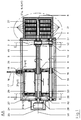
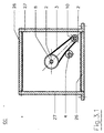
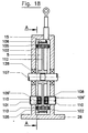
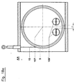
- Fig. 1 shows a measuring cable displacement sensor according to the invention in a sectional view along the longitudinal direction 50, which coincides with the axis of rotation of the central shaft 8 on which the cable drum 5 is longitudinally displaceable but non-rotatable is stored.
- the shaft 8 penetrates the end plates 27, which together with the closed profile 26 form the central housing, each to the outside.
- the left end is on the central shaft 8, which is in the end plates 27 is also mounted, the angle of rotation sensor 24 is rotatably arranged, which by means of a Pot-shaped sensor housing 25 is covered, which with the open edges attached to the left end plate 27, in particular screwed.
- the right end of the central shaft 8 is one Flat spring cascade 1, consisting of several axially one behind the other arranged coil springs, which arranged the return drive for the Rope drum 5 represents.
- the individual coil springs are each in individual spring housings 21 housed, and overall this return drive is by a pot-shaped spring motor housing, which with the open side on the Outside surface of the right end plate 27 is attached to the environment sealed.
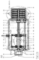
- the central housing is through a closed box section 26, which as Extruded profile can be produced, formed, as best shown in FIGS. 2 and 3 can be seen on which face the end plates 27 are screwed.
- the screw channels are located - like Figures 2 and 3 show - on the inside of the profile.
- FIG. 7 shows, there are undercut grooves with an approximate circular cross section in the undercut area by the thread a self-tapping screw.
- FIG. 1.1 shows a solution in which the central housing likewise from a closed, box-shaped profile 26 with screw channels 43 and end plates 27 placed thereon, however, the course direction of the Box profile 26 transverse to the longitudinal direction 50 and thus transverse to the direction of Shaft 8 runs, thus cover plates 27 parallel to shaft 8.
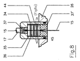
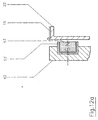
- Fig. 2 also shows the arrangement of the cable inlet viewed in the longitudinal direction in one of the corners of the approximately square profile 26, however, in the longitudinal direction - as can be seen in FIG. 1 - in the middle of the profile 26.
- the rope inlet is shown in Fig. 8 in an enlarged view.
- the pot-shaped Base body 44 has a through opening in the bottom of this pot shape, and is inserted sealed in a corresponding opening of the profile 26.
- In the small passage opening there is a cable duct from a highly wear-resistant material with a funnel-shaped widening towards the outside Opening. At the narrowest point of the passage, the opening in the Rope bushing 37 close to the measuring rope 15.
- Fig. 8a shows how by the abutment of the wire wipers 34 on the measuring rope 15 Cable scraper 34 according to the direction of the measuring cable 15 due to Sliding friction is formed on the measuring cable in the corresponding direction become.
- Fig. 1 shows the cable drum 5 in the left end position of its longitudinal displacement.
- the cable drum 5 is arranged concentrically to the shaft 8, which in the Displacement of the cable drum 5 is designed as a multi-tooth shaft, as on best seen in Fig. 2.
- the cable drum 5 has a through opening in which a sleeve-shaped multi-tooth nut is rotatably connected to the cable drum 5, the Inner profile longitudinally displaceable but non-rotatable on the outer profile of the Multi-tooth shaft 8 sits.
- the flat-form spring cascade 1 tensions the cable drum 5 in the winding direction before, so that in the end position shown in Fig. 1 Measuring rope 15 is completely wound on the measuring rope drum 5, and therefore that at the end of the measuring rope attached rope stop 16 on the Damping element 17 of the rope inlet is applied.
- the Cable drum 5 in the longitudinal direction 50 between the two transverse to the longitudinal direction 50 arranged end plates 6 of a carriage 42 arranged, the one End plates 6 connecting link piece 7, which on the Threaded spindle 10 is seated.
- the link pipe piece 7 and the end plates 6 are through Bushings connected to each other, of which the left one as a slide bearing bushing 20 compared to the smooth, threadless outer contour in this area Threaded spindle 10 is formed, the right hand spindle nut 19, the cooperates with the external thread of the threaded spindle 10.
- the end plates 6 there are 8 receiving bores in alignment with the central shaft, in which the multi-tooth nut 9, which consists of two from the end faces of the insertable items can consist of deep groove ball bearings 28 or Slide bearing is mounted radially.
- the measure of the longitudinal displacement of the carriage 42 and thus the cable drum 5 per revolution of the cable drum 5 is thus on the one hand by the slope of the Thread of the threaded spindle 10 and the spindle nut 19 determined, on the other hand but also by the gear ratio of the additional gear 52, consisting of the two toothed belt pulleys 2 and the toothed belt 3.
- the transmission ratio of this toothed belt gear 52 can be Exchange of one or both of the toothed belt pulleys with a larger one smaller diameter can be changed in a simple manner.
- To the Compensating the changing loop length as a result is - as in FIG. 3 to recognize - a tension roller 4 arranged on the toothed belt 3 attacking an eccentric outer contour, so that by turning the toothed belt 3 in a tense position can be deflected.
- FIG. 3.1 shows a cross-sectional view analogous to FIG. 3, but sectioned in the solutions of FIGS. 1.1 and 1.1a, that is to say a profile 26 including its screw channels 43 transverse to the longitudinal direction of the shaft 8.
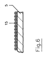
- the longitudinal displacement of the Rope drum 5 can be set so that - as in the enlarged view of the 5 can be seen - the individual windings of the measuring cable 15 on the Measuring rope drum 5 close to each other, but without mutual contact come to lie. This reduces wear on the measuring rope.
- FIG. 4 also shows that instead of the axially acting deep groove ball bearings 28 of FIG. 1 the measuring cable drum 5 also without contact with respect to the end plates 6 of the Carriage 42 can be guided:
- the magnets of the measuring cable drum 5 on the one hand and the respective end plate 6 on the other hand they face each other with the same pole so that they face each other repel each other. As a result, the measuring rope drum 5 automatically turns into the middle between the two end plates 6.
- FIG. 5a in a side view and FIG. 5b in a top view can the magnets 29 by cup-shaped pole shoes 29 ', which act as flux guides act and z. B. consist of soft iron, be surrounded. The open side of the Pole shoe points to the opposite magnet.
- Thrust washers 30 made of low-friction material, such as Teflon or another plastic.
- the solution according to FIG. 1a differs from that according to FIGS. 1 and likewise the solution according to FIG. 1.1a from that according to FIG. 1.1 Brake magnets 53 which between the measuring cable drum 5 and the end plates 6 of the Carriage 42 act, and for this purpose on the end plates 6 close to The outer circumference of the measuring cable drum 5 are arranged, and against their Face plates are directed, as better in detail in Figures 12a and 12b evident.
- These brake magnets 53 cause both when pulling and when winding the measuring cable on the measuring cable drum 5 braking, and thus a defined, clean winding and unwinding of the measuring rope 15. According to Fig.
- the brake magnet 53 is surrounded by a cup-shaped pole piece 53 ', and 12b, the pole piece 53 is simultaneously designed as a threaded bolt and with its external thread in the longitudinal direction in the carriage 42 screwable, whereby the distance from the measuring cable drum 5 and thus the braking effect is adjustable.
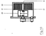
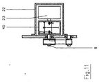
- Figures 9-11 show other solutions for the return drive instead of Flat-shaped spring cascade 1 shown in FIG. 1.
- FIG. 9 instead whose uses an electric motor 23 with appropriate control, which - analogous to the spring cascade 1 - sits coaxially on the right end of the shaft 8 and is covered by a corresponding pot-shaped motor housing 22.
- the electric motor 23 is not directly connected to the shaft 8 connected, but a gear 40, in particular a gear transmission, for appropriate intermediate or step-down ratio.
- such a gear 40 in particular a Gear transmission, between a spiral spring 41 or a flat spring and the shaft 8 interposed.
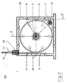
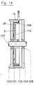
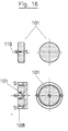
- 13 and 14 each show the cable drum 5, which is attached to a shaft and can thus rotate about its axis of rotation 107.
- the Shaft supported by bearings 128 in the housing, which consists of a box-shaped, preferably closed, profile 26.
- the cable drum 5 consists of a winding cylinder 105 which extends radially outwards pointing, limiting stops on both faces for the on the Winding surface 106, the outer circumference of the winding cylinder 105 to be wound up Measuring rope 15 has.
- the winding cylinder 105 is single-stage Spokes or a spoke plate in the hub area of the winding drum.
- the at least one brake magnet 101 is one Wall of the profile 26 arranged, the drum plate 112 in a small axial Distance is opposite, so that only a small air gap between the Brake magnet 101 and the drum plate 112 is made.
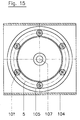
- the brake magnet (s) 101 are in the radially outer region of the cable drum 5, arranged close to or in the area of its winding cylinder 105, specifically via distributed the circumference, as Fig. 15 shows.
- An elevation on this wall of the housing 104 serves as contact protection 113, thus to prevent the rope drum 5 from sticking to the brake magnet 101 in the axial direction.
- FIG. 13a shows, especially in the axial direction Towards the center of the drum plate 112 - the brake magnets 101 of both Pages aligned in the axial direction against this drum plate 112 his.
- the two brake magnets 101 which have different poles against the Drum plate 112 can be directed on the inside of a U-shaped Magnet holder 109 may be attached, which is the radially outer end of the cable drum 5 encompasses, and in particular is also displaceable in the radial direction Change in braking force.
- FIG. 13b also shows from both axial directions against the drum plate 112 directed brake magnets 101, which - however Contrary to the brake magnet 101 in Fig. 13a - a magnetization axis 110 parallel to the drum plate 112, namely in the radial direction of the drum plate, have, and each surrounded by plate-shaped pole pieces 108 are.
- magnets are used as brake magnets 101, which are shown in FIG. 16 are shown in two versions in front and side view. It is can be seen that in both cases the actual brake magnet 101 in Direction of passage through the thickness of the disc is magnetized so that the one Face represents the north pole and the other the south pole. 16 lower embodiment is the south pole and the extent of the disk-shaped magnet by a pot-shaped, one-piece pole piece 108 Covered from soft iron, which in function of the south pole of this magnet is shifted by the field lines outside the south pole through the pole piece 108 through to the open front of the cup-shaped pole piece.
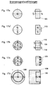
- 17 show different types of magnetization of disk-shaped Magnets.
- 17a corresponds to the solution according to FIG. Fig. 16, with each entire face of the disk corresponds to a pole, i.e. north pole or south pole.
- the axial direction of the disk is thus the magnetization axis.
- the magnetization axis is parallel to the disk plane in FIG. 17a '.
- 17c shows a similar magnetization in different sectors in FIG Circumferential direction, but here is the disk of the magnet in Direction of passage not magnetized through, but only one of the end faces magnetized overall, so that this magnetized face as one in Considered circumferential direction as a string of differently shaped Bar magnets can be viewed (sectoral lateral magnetization on an area).
- FIG. 17d shows the magnet of FIG. 17a surrounded by a cup-shaped one Pole shoe, as already shown in FIG. 16, lower illustration, and is described.
- Figures 17e-17h show bar magnets.
- the solution in Fig. 17e is the longitudinal direction of the rod the direction of magnetization, i.e. with the north pole on one narrow end and the South Pole on the opposite narrow end.
- the direction of magnetization 110 runs transversely to Longitudinal extension of the bar magnet, i.e. with the north pole on one Broadside and the South Pole on the other broadside.
- FIG. 17g which is additionally of a U-shaped one Pole 108, preferably made of soft iron, is surrounded, the free ending legs are arranged parallel to the South Pole and North Pole surfaces.
- the cable drum 5 is in the by means of its axis and bearings 128 Side walls of a profile 26 mounted, which serves as a housing.
- the spoke plate 112 of the cable drum 5 in the axial direction centered on the winding cylinder 105 arranged, the outer surface, the winding surface 106, by a measuring rope 15th wound, is shown.
- the spoke plate 112 In the lower half of Fig. 18 are on the Inner surface of the winding cylinder 105 with respect to the spoke plate 112
- two rod-shaped holding magnets 102 arranged with opposite poles against each other, i.e. against the drum plate 112, point.
- the holding magnets 102 are preferably somewhat in the longitudinal direction over the outer surfaces of the cable drum 5.
- the attachment is preferably done by Glue.
- the 18 also has a pair of in the lower half of the image Brake magnet 101 on. However, these are on the side walls of the profile 26 arranged and reach - radially within the winding cylinder 105 - to close the drum plate 112 of the cable drum 5.
- the two brake magnets 101 - which in turn with their Magnetization direction arranged parallel to the axis of rotation 107 and with opposite poles are aligned to each other - each in Indentations in the end faces of magnet holders 109 which are directed towards one another arranged, which have an external thread, with the help of which they are in a corresponding, axially running threaded hole through the wall of the Profiles screwed through and thus with regard to the size of the air gap are adjustable.
- the two brake magnets 101 are located to increase the Magnetic force in each case in a cup-shaped pole piece 108, the open side of which each also in the direction of the drum plate 112 and thus on the opposite brake magnets 101 are prepared.
- FIG. 18a furthermore shows the possibility of not just one, but several of them distributed along the circumference Brake magnets 101 in magnet holders 109 in the walls of the profile 26 to be arranged, with a minimum distance a between them, to have a negative mutual influence on the brake magnets 110 prevent.
- Fig. 18a further shows that it is not necessarily uniform over the circumference Distribution of the brake magnets 101 or magnet holder 109 are available got to.
- the holding magnets 102 are not for reasons of clarity drawn.
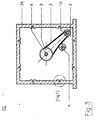
- FIG. 19 shows another front view of the cable drum 5 according to FIG. the line A-A 18.
- FIG. 20 shows a solution that differs from FIG. 19 by an additional sliding band 111.
- This finite
- the one end of the slide belt 111 is at a fixed point 115 Attached to the housing near the cable inlet, while the other end is fixed to the housing about an adjustment point 116 on the opposite side of the axis of rotation 107 of the cable drum 5.
- the adjustment point 116 can be displaced both tangentially and radially with respect to the axis 107 of the cable drum 5 , in particular in two mutually perpendicular directions, each transverse to the axis of rotation 107.
- the loose or completely missing contact between the sliding band 111 and the outside of the rope winding can be adjusted to intensify or loosen the contact with the aim of a To prevent "rising", ie radial lifting, of the measuring cable if the combination magnets 102 'or the holding magnets 102 prove to be insufficient.
- the rising can already be prevented by essentially no contact between the sliding band 111 and the outside of the measuring cable winding is present, since this contact only occurs when the measuring cable undesirably rises in the radial direction to the outside.
- the possible distance between the outer surface of the cable winding and the inner surface of the tether must be set as small as possible, ideally approximately zero .
- 20a shows a solution in which the sliding band 111 does not loosely around the rope-wound drum is laid around, but as a covering on one Slide shoe 114 is located, the contour of the cable drum 5 facing Corresponds to the outer contour of the wound rope drum 5.
- the shoe 114 extends around 90 ° around the outer circumferential surface of the cable drum 5, namely in the winding direction in the to the run-up point of the cable drum subsequent segment.
- the slide shoe 114 is attached to the housing 104, in particular screwed and positioned so that it is made of 111 existing covering the desired contact to the outer surface of the rope winding the cable drum 5, as the sectional view B-B shows.
Abstract
Description
- Fig. 1
- Längsschnitte durch Meßseil-Wegsensoren;
- Fig. 2
- einen Querschnitt entlang der Linie A-A;
- Fig. 3
- Querschnitte entlang der Linie B-B;
- Fig. 4
- eine vergrößerte Detaildarstellung des Schlittens 42 aus Fig. 1;
- Fig. 5:
- Detailansichten der Lagerungsmagnete aus Fig. 4;
- Fig. 6
- eine vergrößerte Detaildarstellung der bewickelten Seiltrommel aus Fig. 1;
- Fig. 7
- eine vergrößerte Detaildarstellung aus Fig. 3;
- Fig. 8
- eine vergrößerte Detaildarstellung des Seileinlaufes aus Fig. 1;
- Fig. 9
- im Längsschnitt eine andere Variante eines Rückstellantriebes;
- Fig. 10
- im Längsschnitt eine dritte Variante eines Rückstellantriebes;
- Fig. 11
- im Längsschnitt eine vierte Variante eines Rückstellantriebes;
- Fig. 12:
- Detaillösungen der Bremsmagnete.
- Fig. 13:
- die Bremsmagnete im Gehäuse,
- Fig. 14:
- die Bremsmagnete in der Seiltrommel,
- Fig. 15:
- eine Frontansicht der Seiltrommel der Fig. 14,
- Fig. 16:
- Detaildarstellungen der Bremsmagnete,
- Fig. 17:
- unterschiedlich magnetisierte Magnete,
- Fig. 18:
- einen Schnitt durch eine weitere Ausführungsform eines Meßseil-Wegsensors,
- Fig. 19:
- eine Ansicht der Seiltrommel aus Fig. 18 und
- Fig. 20:
- eine weiter Bauform des Meßseilwegsensors.
- bei den Haltemagneten das durch die Magnete beaufschlagte Meßseil 15 aus einem magnetisierbaren Material bestehen muß, bzw.
- bei den Bremsmagneten das beeinflußte Bauteil (also bei Anordnung der Bremsmagnete an der Seiltrommel das Gehäuse oder bei Anordnung der Bremsmagneten am Gehäuse die Seiltrommel (wenigstens im beeinflußten Bereich) aus elektrisch leitfähigem Material bestehen muß oder beschichtet sein muß.
- 1
- Flachformfederkaskade
(Spiralfeder) - 2
- Zahnriemenscheiben
- 3
- Zahnriemen
- 4
- Spannrolle mit Exzenter
- 5
- Seiltrommel
- 6
- Endplatten
- 7
- Kulissenrohrstück
- 8
- Vielzahnwelle
- 9
- Vielzahnmutter
- 10
- Gewindespindel
- 15
- Meßseil
- 16
- Seilanschlagstück
- 18
- Seildurchführung
(Baugruppe, kaskadiert) - 19
- Spindelmutter
- 20
- Gleitlagerbuchse
- 21
- Einzelfedergehäuse
- 22
- Motorgehäuse
- 23
- Elektromotor
- 24
- Drehwinkelsensor
- 25
- Sensorgehäuse
- 26
- Profil
- 27
- Stirnplatten
- 28
- Wellenlager
- 29
- Permanentmagnete
- 29'
- Flußstück (Weicheisen)
- 30
- Anlaufscheibe
- 34
- Seilabstreifer
- 35
- Abstandsring für Seilabstreifer
- 36
- Hohlraum für Schmutzablagerung
- 37, 37'
- Seildurchführung
(Einzelteil) - 40
- Getriebe
- 41
- Spiralfeder
- 42
- Schlitten
- 43
- Schraubkanal
- 44
- Grundkörper
- 45
- Innenraum
- 50
- Längsrichtung
- 51
- Spindelantrieb
- 52
- Getriebe
- 53
- Bremsmagnet
- 54
- Bremsscheibe
Seilhaftmagnete - 101
- Bremsmagnet
- 102
- Haltemagnet
- 102'
- Kombimagnete
- 103
- Einwirkbereich
- 104
- Gehäuse
- 105
- Wickelzylinder
- 106
- Wickelfläche
- 107
- Achse
- 108
- Polschuh
- 109
- Verstellschraube und Magnethalter
- 110
- Magnetisierungsachse
- 111
- Gleitband
- 112
- Trommelplatte
- 113
- Kontaktschutz
- 114
- Gleitschuh
- 115
- Festpunkt
- 116
- Verstellpunkt
- 128
- Lager
- 130
- Gleitrolle
Claims (17)
- Meßseil-Wegsensor mitdadurch gekennzeichnet, daßeinem Gehäuse,einer im Gehäuse drehbar, zur Drehachse in Längsrichtung (50) längsverschiebbar, angeordneten Seiltrommel (5),einer gehäusefest angeordneten Seildurchführung (18) für das Meßseil (15),einem Längsantrieb für die Seiltrommel (5) mit einem Spindelantrieb (51), welcher eine Gewindespindel (10) umfaßt, die relativ zu einer Spindelmutter (19) verschraubbar ist,
der Längsantrieb ein zusätzliches Getriebe (52) aufweist, das die Drehung der Seiltrommel (5) auf den Spindelantrieb (51) überträgt. - Meßseil-Wegsensor nach Anspruch 1,
dadurch gekennzeichnet, daß
die Gewindespindel (10) exzentrisch zur Drehachse der Seiltrommel (5), insbesondere außerhalb der Seiltrommel (5) und parallel zur Drehachse der Seiltrommel (5) angeordnet ist. - Meßseil-Wegsensor nach einem der vorhergehenden Ansprüche,
dadurch gekennzeichnet, daß
das Getriebe (52) ein Riemengetriebe, insbesondere ein Zahnriemengetriebe, ist, und die Riemenscheiben (2) leicht auswechselbar einerseits auf der Gewindespindel (10) und andererseits auf einer mit der Seiltrommel (5) mitdrehenden Welle (8) angeordnet sind, und insbesondere die mit der Seiltrommel (5) mitdrehende Welle (8) zentral zur Seiltrommel (5) angeordnet ist und aufgrund eines unrunden Außenumfanges direkt oder indirekt drehfest, aber längsverschiebbar, mit der Seiltrommel (5) verbunden ist, insbesondere daß die Welle (8) als Vielzahnwelle ausgebildet ist, und insbesondere die Seiltrommel (5) drehbar, axial im wesentlichen fest in einem Schlitten (42) geführt und gelagert ist, welcher die Spindelmutter (19) des Spindelantriebes (51) drehfest trägt und entlang der Vielzahnwelle (8) in Längsrichtung (50) verschiebbar ist. - Meßseil-Wegsensor nach einem der vorhergehenden Ansprüche,
dadurch gekennzeichnet, daß
die Axiallagerung der Seiltrommel (5) im Schlitten (42) berührungsfrei, insbesondere mittels Magneten, insbesondere mittels Permanentmagneten (29), erfolgt. - Meßseil-Wegsensor nach einem der vorhergehenden Ansprüche,
dadurch gekennzeichnet, daß
der Spindelantrieb (51) und/oder das Getriebe (52) innerhalb des Gehäuses des Meßseil-Wegsensors, insbesondere im gleichen Innenraum des Gehäuses wie die Seiltrommel (5) angeordnet ist, und insbesondere ein Rückstellantrieb und ein Drehwinkelsensor (24) mit der Welle (8) wirkverbunden, insbesondere koaxial auf dieser angeordnet sind, insbesondere an den zwei gegenüberliegenden Enden der Welle (8) und insbesondere in separaten Räumen des Gehäuses des Drehwinkelsensors, und insbesondere es sich bei dem Rückstellantrieb um eine Flachformfeder, insbesondere um eine Flachformfeder-Kaskade (1) handelt, und insbesondere die Flachformfeder-Kaskade (1) aus axial hintereinander angeordneten Flachformfedern, die in parallelen Ebenen zueinander liegen und so angeordnet sind, insbesondere wirkungsmäßig in Reihenschaltung angeordnet sind, so daß insbesondere nach dem zeitweisen Spannen der ersten Flachformfeder das Spannen der nächsten Flachformfeder vollzogen wird. - Meßseil-Wegsensor nach einem der vorhergehenden Ansprüche,
dadurch gekennzeichnet, daß
das Gehäuse ein Profil (26), insbesondere ein geschlossenes, hohles, insbesondere innen eckiges, Kastenprofil, umfaßt, welches in Längsrichtung (50) des Meßseil-Wegsensors verläuft und stirnseitig durch, insbesondere aufgeschraubte Stirnplatten (27) verschlossen ist, und insbesondere das Profil (26) auf den Innenseiten nach innen hin offene, hinterschnittene Schraubkanäle (43) aufweist, die zum Einschrauben von selbstschneidenden Schrauben von der Stirnseite her geeignet sind, und insbesondere die Welle (8) und/oder die Gewindespindel (10) in den Stirnplatten (27) des Gehäuses gelagert sind. - Meßseil-Wegsensor miteiner Seiltrommel (5) zum Aufwickeln des Meßseiles (15) auf der äußeren Wickelfläche (106) des Wickelzylinders (105) der Seiltrommel (5), undeinem Gehäuse, in welchem die Seiltrommel (5) gelagert ist,
dadurch gekennzeichnet, daßwenigstens ein Bremsmagnet (101) an einem nicht mit der Seiltrommel (5) mitdrehenden Punkt so angeordnet ist, daß er berührungslos magnetisch auf die Seiltrommel (5) an einem exzentrischen Einwirkbereich (103') gegen die Drehrichtung bremsend einwirkt, unddie Seiltrommel (5) wenigstens im Einwirkbereich (103') aus elektrisch leitfähigem Material besteht, und insbesondere der Bremsmagnet (101) am Gehäuse (104) angeordnet ist. - Meßseil-Wegsensor miteiner Seiltrommel (5) zum Aufwickeln des Meßseiles (15) auf der äußeren Wickelfläche (106) des Wickelzylinders (105) der Seiltrommel (5), undeinem Gehäuse, in welchem die Seiltrommel (5) gelagert ist,
dadurch gekennzeichnet, daßwenigstens ein Bremsmagnet (101) an der Seiltrommel (5) exzentrisch so angeordnet ist, daß er berührungslos magnetisch auf das Gehäuse in Drehrichtung bremsend einwirkt, unddas Gehäuse (4) wenigstens im Einwirkbereich (103') aus elektrisch leitfähigem Material besteht. - Meßseil- Wegsensor miteiner Seiltrommel (5) zum Aufwickeln des Meßseiles (15) auf der äußeren Wickelfläche (106) des Wickelzylinders (105) der Seiltrommel (5), undeinem Gehäuse, in welchem die Seiltrommel (5) gelagert ist,
dadurch gekennzeichnet, daßan der Seiltrommel (5) radial innerhalb der Mittelfläche (106) des Wickelzylinders (105) wenigstens ein Haltemagnet (102) angeordnet ist zum Halten des Meßseiles (15) radial nach innen an der Wickelfläche (106), unddas Meßseil (15) aus magnetisierbarem Material besteht. - Meßseil-Wegsensor mitdadurch gekennzeichnet, daßeiner Seiltrommel (5) zum Aufwickeln des Meßseiles (15) auf der äußeren Wickelfläche (106) des Wickelzylinders (105) der Seiltrommel (5), undeinem Gehäuse, in welchem die Seiltrommel (5) gelagert ist,
um wenigstens einen Teil des Außenumfanges der ganz oder teilweise mit Meßseil (15) beweglichen Wickelfläche (106) ein Gleitband (111), insbesondere ein Band aus Textilmaterial, insbesondere ein Gleitband oder ein Band aus anderem gleitfähigen, nicht abrasiven Material, in geringem Abstand und/oder an dem Außenumfang der Bewicklung mit Meßseil schleifend herumgeführt ist und der Abstand, bzw. Anpreßdruck des Bandes gegen die Bewicklung mit Meßseil (15) einstellbar ist.. - Meßseil-Wegsensor nach einem der Ansprüche 7 bis 10,
dadurch gekennzeichnet, daß
der an der Seiltrommel (5) angeordnete mindestens eine Bremsmagnet (101) und/oder Haltemagnete (102) jeweils gleichmäßig über den Umfang verteilt, insbesondere paarweise zur Vermeidung von Unwucht an der Seiltrommel angeordnet sind. - Meßseil-Wegsensor nach einem der Ansprüche 7 bis 11,
dadurch gekennzeichnet, daß
die Bremsmagnete (101) mit möglichst großem Abstand zur Rotationsachse (107) der Seiltrommel (5), insbesondere nahe am Außenumfang der Seiltrommel (105), angeordnet sind, und insbesondere die Bremsmagnete (101) und/oder die Haltemagnete (102) Permanentmagnete sind, und insbesondere die Haltemagnete mit ihrer Magnetisierungsachse (110) parallel zur Rotationsachse (107) der Seiltrommel (5) angeordnet sind, und insbesondere die Bremsmagnete (101) mit ihrer Magnetisierungsachse (110) parallel zur Rotationsachse (107) der Seiltrommel (5) angeordnet und entgegengesetzt gepolt sind. - Meßseil-Wegsensor nach einem der Ansprüche 7 bis 12,
dadurch gekennzeichnet, daß
die Bremsmagnete (101) mit Polschuh-Stücken radial innerhalb sowie radial außerhalb der Magnetisierungsachse (110), insbesondere mit einem tropfförmigen Polschuh-Stück (108), welches nur zu dem beeinflussenden Bauteil hin offen ist, ausgestattet ist. - Meßseil-Wegsensor nach einem der Ansprüche 7 bis 13,
dadurch gekennzeichnet, daß
die Bremsmagnete (101) und/oder die Haltemagnete (102) in einem Magnethalter (109) aufgenommen sind, dessen Position in axialer Richtung gegenüber dem zu beeinflussenden Bauteil einstellbar, insbesondere stufenlos einstellbar, ist, und insbesondere der Magnethalter (109) ein Gewindebolzen ist, an dessen einer Stirnseite der Bremsmagnet (101) und/oder Haltemagnet (102) gegen das zu beeinflussende Bauteil hin gerichtet angeordnet ist. - Meßseil-Wegsensor nach einem der Ansprüche 7 bis 14,
dadurch gekennzeichnet, daß
als Bremsmagnete (101) beidseits der Seiltrommel (5) gegenüberliegend und in Längsrichtung mit entgegengesetzten Polen gegeneinanderweisende Magnete in Längsrichtung fluchtend angeordnet sind, und insbesondere als Bremsmagnete (101) scheibenförmige Magnete verwendet werden, deren Magnetisierungsachse (110) der Dicke des scheibenförmigen Magneten entspricht, und insbesondere als Bremsmagnete (101) scheibenförmige Magnete verwendet werden, die in Sektoren unterteilt sind, wobei die einzelnen Sektoren als Einzelmagnete wirken, deren Magnetisierungsachsen (10) jeweils der Dicke des scheibenförmigen Magneten entsprechen, wobei die Polung der einzelnen Sektoren entlang des Umfanges wechselt. - Meßseil-Wegsensor nach einem der Ansprüche 7 bis 14,
dadurch gekennzeichnet, daß
als Bremsmagnete (101) scheibenförmige Magnete verwendet werden, bei denen nur eine der Hauptflächen magnetisiert ist durch sektorenförmig abwechselnde Magnetisierung in Umfangsrichtung. - Meßseil-Wegsensor nach einem der Ansprüche 7 bis 16,
dadurch gekennzeichnet, daß
der bzw. die. Bremsmagnete (101) und der bzw. die Haltemagnete (102) gemäß einem der vorhergehenden Ansprüche in jeweils einem Kombimagnet funktionsvereinigt sind.
Applications Claiming Priority (2)
| Application Number | Priority Date | Filing Date | Title |
|---|---|---|---|
| DE19859445A DE19859445C2 (de) | 1998-12-22 | 1998-12-22 | Meßseil-Wegsensor mit einem Längsantrieb für die Seiltrommel |
| DE19859445 | 1998-12-22 |
Publications (3)
| Publication Number | Publication Date |
|---|---|
| EP1014031A2 true EP1014031A2 (de) | 2000-06-28 |
| EP1014031A3 EP1014031A3 (de) | 2001-01-24 |
| EP1014031B1 EP1014031B1 (de) | 2006-03-01 |
Family
ID=7892253
Family Applications (1)
| Application Number | Title | Priority Date | Filing Date |
|---|---|---|---|
| EP99125634A Expired - Lifetime EP1014031B1 (de) | 1998-12-22 | 1999-12-22 | Messseil-Wegsensor mit einem Längsantrieb für die Seiltrommel |
Country Status (4)
| Country | Link |
|---|---|
| US (1) | US6561451B1 (de) |
| EP (1) | EP1014031B1 (de) |
| DE (2) | DE19859445C2 (de) |
| ES (1) | ES2259826T3 (de) |
Cited By (14)
| Publication number | Priority date | Publication date | Assignee | Title |
|---|---|---|---|---|
| EP1241124A2 (de) * | 2001-03-16 | 2002-09-18 | Fernsteuergeräte Kurt Oelsch GmbH | Zwangsführung bei einem Seillängengeber |
| GB2385423A (en) * | 2002-01-16 | 2003-08-20 | Ctex Seat Comfort Ltd | A component position indicating system |
| DE102006020779B3 (de) * | 2006-05-03 | 2008-01-10 | Waycon Positionsmesstechnik Gmbh | Messseil-Wegsensor |
| EP2653428A1 (de) * | 2012-04-16 | 2013-10-23 | Fernsteuergeräte Kurt Oelsch GmbH | Seillängengeber |
| CN107265204A (zh) * | 2017-07-06 | 2017-10-20 | 孙海合 | 一种用于废旧信号线自动卷起设备 |
| CN107618962A (zh) * | 2017-11-06 | 2018-01-23 | 杨公民 | 一种水平移动电梯的自动转向装置 |
| CN108313857A (zh) * | 2018-01-04 | 2018-07-24 | 中信重工机械股份有限公司 | 一种永磁直驱内装式提升机 |
| CN109883309A (zh) * | 2019-01-28 | 2019-06-14 | 中国船舶重工集团公司第七一五研究所 | 一种基于磁性感应原理的缆绳到位传感装置 |
| WO2019229778A1 (en) * | 2018-05-29 | 2019-12-05 | Tecna S.P.A. | Balancer for tools |
| CN110863425A (zh) * | 2019-12-09 | 2020-03-06 | 河南交院工程技术有限公司 | 一种桥体结构 |
| CN112525039A (zh) * | 2020-12-15 | 2021-03-19 | 刘川 | 高速公路桥梁基础沉降位移测量装置及其使用方法 |
| CN115808111A (zh) * | 2023-01-05 | 2023-03-17 | 深圳联颖通讯有限公司 | 一种通讯电缆长度测量仪 |
| CN116239015A (zh) * | 2023-05-09 | 2023-06-09 | 河南省格兴智能科技有限责任公司 | 一种起重机吊具减摇缓冲稳固装置及其操作系统 |
| CN117381715A (zh) * | 2023-12-11 | 2024-01-12 | 山西省水利水电工程建设监理有限公司 | 大口径管道安装对接定位装置及其方法 |
Families Citing this family (34)
| Publication number | Priority date | Publication date | Assignee | Title |
|---|---|---|---|---|
| DE10311103B4 (de) * | 2003-03-06 | 2007-06-06 | Muammer Atar | Vorrichtung zum Aus- und Einfahren eines flexiblen Bandes, einer Schnur oder eines Kabels aus bzw. in ein Gehäuse |
| KR20060132651A (ko) * | 2003-12-24 | 2006-12-21 | 쓰리엠 이노베이티브 프로퍼티즈 컴파니 | 표면 프로파일을 측정하기 위한 장치 및 방법 |
| FR2879734B1 (fr) * | 2004-12-22 | 2007-03-02 | Ind Sarl Ak | Dispositif d'entrainement pour capteur a cable |
| FR2887865B1 (fr) * | 2005-07-01 | 2007-09-07 | Delachaux Sa Sa | Enrouleur a ressorts freine a l'enroulement |
| WO2007095932A1 (de) * | 2006-02-23 | 2007-08-30 | Micro-Epsilon Messtechnik Gmbh & Co. Kg | Seillängengeber |
| US7395609B2 (en) * | 2006-09-26 | 2008-07-08 | Spaceage Control, Inc. | 3-dimensional cable guide and cable based position transducer |
| US8702067B2 (en) * | 2007-08-24 | 2014-04-22 | Heerema Marine Contractors Nederland Se | Axial displacement device, line deployment system, and a method for deploying a line |
| NZ575464A (en) * | 2009-03-10 | 2010-07-30 | Holmes Solutions Ltd | Improvements in and relating to braking mechanisms |
| US8970211B1 (en) * | 2009-04-23 | 2015-03-03 | See Scan, Inc. | Pipe inspection cable counter and overlay management system |
| CN101885436B (zh) * | 2010-07-08 | 2011-11-30 | 四川川东电缆有限责任公司 | 一种盘式成缆机、笼式成缆机及机用线盘 |
| US8720811B2 (en) | 2011-03-07 | 2014-05-13 | Stoneage, Inc. | Apparatus and method for storing and dispensing a pressure hose |
| NZ619034A (en) | 2013-12-16 | 2015-03-27 | Eddy Current Ltd Partnership | An assembly to control relative speed of movement between parts |
| US10498210B2 (en) | 2014-08-18 | 2019-12-03 | Eddy Current Limited Partnership | Tuning of a kinematic relationship between members |
| KR102449222B1 (ko) | 2014-08-18 | 2022-09-28 | 에디 커런트 리미티드 파트너쉽 | 부재들 사이의 운동학적 관계의 조정 |
| WO2016028170A1 (en) | 2014-08-18 | 2016-02-25 | Eddy Current Limited Partnership | Latching devices |
| US10532662B2 (en) | 2014-08-20 | 2020-01-14 | TruBlue LLC | Eddy current braking device for rotary systems |
| WO2016089226A1 (en) | 2014-12-04 | 2016-06-09 | Eddy Current Limited Partnership | Methods of altering eddy current interactions |
| CN107005141B (zh) | 2014-12-04 | 2020-08-28 | 涡流有限合伙公司 | 涡流制动器装置 |
| BR112017010643B1 (pt) | 2014-12-04 | 2022-03-03 | Eddy Current Limited Partnership | Aparelho de absorção de energia |
| SG11201704342RA (en) | 2014-12-04 | 2017-06-29 | Eddy Current Ltd Partnership | Latch activation between elements |
| EP3227991A4 (de) | 2014-12-04 | 2018-08-01 | Eddy Current Limited Partnership | Getriebe mit wirbelstrombremsung |
| EP3391060B1 (de) | 2015-12-18 | 2022-04-20 | Eddy Current Limited Partnership | Kontrollmechanismus für variables verhalten für ein antriebssystem |
| DE102016003037B4 (de) | 2016-03-11 | 2018-10-31 | eddylab GmbH | Seilzugsensor mit einem gedämpften Federantrieb |
| DE102016004731B4 (de) * | 2016-04-19 | 2017-10-12 | eddylab GmbH | Seilzugsensor mit einer druck- und mediendichten Seildurchführung |
| DE102016004989B4 (de) | 2016-04-25 | 2017-12-21 | eddylab GmbH | Seilzugsensor mit einer Seildüse mit integrierter Verschleißerkennung |
| CN106044609B (zh) * | 2016-06-08 | 2018-03-16 | 中国铁路设计集团有限公司 | 测夹片回缩值装置及带该装置的智能千斤顶 |
| DE102016114053A1 (de) | 2016-07-29 | 2018-02-01 | Cl Schutzrechtsverwaltungs Gmbh | Pulvermodul für eine Vorrichtung zur additiven Herstellung dreidimensionaler Objekte |
| CN107128748B (zh) * | 2017-04-04 | 2018-07-24 | 苏州交通工程集团有限公司 | 一种桥梁设备 |
| CN106966238B (zh) * | 2017-04-04 | 2018-08-31 | 诸暨市鼎鼎商务服务有限公司 | 一种桥梁设备 |
| CN108313834A (zh) * | 2017-12-04 | 2018-07-24 | 安徽皖电机械设备有限公司 | 一种线缆线盘架 |
| AU2020288450A1 (en) * | 2019-06-06 | 2022-02-03 | Mti Group Pty Ltd | Down hole measurement system |
| CN111691440B (zh) * | 2020-06-24 | 2021-07-23 | 江西理工大学 | 一种边坡预警用位移放大装置 |
| WO2022238988A1 (en) * | 2021-05-13 | 2022-11-17 | Enervibe Ltd | Rotation energy harvester |
| DE102021128974B3 (de) | 2021-11-08 | 2023-03-23 | Fernsteuergeräte Kurt Oelsch GmbH | Seillängengeber mit elektrischem Antrieb |
Citations (5)
| Publication number | Priority date | Publication date | Assignee | Title |
|---|---|---|---|---|
| DE729362C (de) * | 1941-01-28 | 1942-12-19 | Eduard Mange | Seilwickler fuer Windentrommeln o. dgl. |
| US4443888A (en) * | 1982-03-29 | 1984-04-17 | Litton Industrial Products, Inc. | SID Monitor |
| US4655399A (en) * | 1984-03-31 | 1987-04-07 | Vernon Harvey B W | Irrigation or other machine having a rotatable drum carrying a hose or other flexible element wound thereon |
| EP0778239A1 (de) * | 1995-12-04 | 1997-06-11 | Fernsteuergeräte Kurt Oelsch GmbH | Seillängengeber mit längsbeweglicher Seiltrommel |
| DE29816005U1 (de) * | 1998-09-05 | 1998-12-17 | Feyrer Klaus Prof Dr Ing | Schachtförderanlage mit Trommelwinde |
Family Cites Families (15)
| Publication number | Priority date | Publication date | Assignee | Title |
|---|---|---|---|---|
| US1811945A (en) * | 1928-07-30 | 1931-06-30 | Emil G Lange | Steel tape reel |
| US1947392A (en) * | 1931-03-02 | 1934-02-13 | Guntermann Wilhelm | Hollow rod |
| US2809435A (en) * | 1955-12-19 | 1957-10-15 | California Research Corp | Apparatus for maintaining proper depth correlation in well logging apparatus |
| US3167865A (en) * | 1962-04-11 | 1965-02-02 | Steinberg Solomon | Automatic system for web length measurment |
| DE2903096A1 (de) * | 1979-01-27 | 1980-07-31 | Grieshaber Vega Kg | Elektromechanisches fuellstandsmessgeraet |
| GB2085841B (en) * | 1980-10-23 | 1984-06-27 | Gadd Jan Albert | Reel device with brake |
| DE3539884A1 (de) * | 1985-11-11 | 1987-05-21 | Duesterloh Gmbh | Seilwickelvorrichtung |
| DE3621234A1 (de) * | 1986-06-25 | 1988-01-21 | Thyssen Edelstahlwerke Ag | Senkrecht-giessanlage fuer strang-teillaengen |
| GB2236589B (en) * | 1989-10-07 | 1993-05-05 | Stc Plc | Laying cables |
| JPH07118901B2 (ja) * | 1990-04-28 | 1995-12-18 | いすゞ自動車株式会社 | 渦電流式減速装置 |
| JP2645634B2 (ja) * | 1992-12-04 | 1997-08-25 | 動力炉・核燃料開発事業団 | 上下動作装置における位置決め機構 |
| DE19726084C2 (de) * | 1997-06-19 | 2001-05-17 | Asm Automation Sensorik Messte | Überdruck-Meßseil-Wegsensor |
| DE29716524U1 (de) * | 1997-09-05 | 1998-02-12 | Oelsch Fernsteuergeraete | Abstreifvorrichtung für Seillängengeber |
| DE19814941A1 (de) * | 1998-04-03 | 1999-10-07 | Westfalia Wst Systemtechnik | Satellitenfahrzeug zum Ein- und Auslagern von Paletteneinheiten bei Transportfahrzeugen |
| DE19925364C3 (de) * | 1999-06-02 | 2003-04-10 | Oelsch Fernsteuergeraete | Seillängengeber zur Erzeugung eines Seillängensignals |
-
1998
- 1998-12-22 DE DE19859445A patent/DE19859445C2/de not_active Expired - Fee Related
-
1999
- 1999-12-22 US US09/468,926 patent/US6561451B1/en not_active Expired - Lifetime
- 1999-12-22 ES ES99125634T patent/ES2259826T3/es not_active Expired - Lifetime
- 1999-12-22 DE DE59913170T patent/DE59913170D1/de not_active Expired - Lifetime
- 1999-12-22 EP EP99125634A patent/EP1014031B1/de not_active Expired - Lifetime
Patent Citations (5)
| Publication number | Priority date | Publication date | Assignee | Title |
|---|---|---|---|---|
| DE729362C (de) * | 1941-01-28 | 1942-12-19 | Eduard Mange | Seilwickler fuer Windentrommeln o. dgl. |
| US4443888A (en) * | 1982-03-29 | 1984-04-17 | Litton Industrial Products, Inc. | SID Monitor |
| US4655399A (en) * | 1984-03-31 | 1987-04-07 | Vernon Harvey B W | Irrigation or other machine having a rotatable drum carrying a hose or other flexible element wound thereon |
| EP0778239A1 (de) * | 1995-12-04 | 1997-06-11 | Fernsteuergeräte Kurt Oelsch GmbH | Seillängengeber mit längsbeweglicher Seiltrommel |
| DE29816005U1 (de) * | 1998-09-05 | 1998-12-17 | Feyrer Klaus Prof Dr Ing | Schachtförderanlage mit Trommelwinde |
Cited By (21)
| Publication number | Priority date | Publication date | Assignee | Title |
|---|---|---|---|---|
| EP1241124A2 (de) * | 2001-03-16 | 2002-09-18 | Fernsteuergeräte Kurt Oelsch GmbH | Zwangsführung bei einem Seillängengeber |
| EP1241124A3 (de) * | 2001-03-16 | 2003-07-02 | Fernsteuergeräte Kurt Oelsch GmbH | Zwangsführung bei einem Seillängengeber |
| GB2385423A (en) * | 2002-01-16 | 2003-08-20 | Ctex Seat Comfort Ltd | A component position indicating system |
| US6768321B2 (en) | 2002-01-16 | 2004-07-27 | Ctex Seat Comfort Limited | Component position indicating apparatus |
| GB2385423B (en) * | 2002-01-16 | 2005-12-07 | Ctex Seat Comfort Ltd | Component position indicating apparatus |
| DE102006020779B3 (de) * | 2006-05-03 | 2008-01-10 | Waycon Positionsmesstechnik Gmbh | Messseil-Wegsensor |
| EP2653428A1 (de) * | 2012-04-16 | 2013-10-23 | Fernsteuergeräte Kurt Oelsch GmbH | Seillängengeber |
| EP2653428B1 (de) | 2012-04-16 | 2015-09-30 | Fernsteuergeräte Kurt Oelsch GmbH | Seillängengeber |
| CN107265204A (zh) * | 2017-07-06 | 2017-10-20 | 孙海合 | 一种用于废旧信号线自动卷起设备 |
| CN107618962A (zh) * | 2017-11-06 | 2018-01-23 | 杨公民 | 一种水平移动电梯的自动转向装置 |
| CN108313857A (zh) * | 2018-01-04 | 2018-07-24 | 中信重工机械股份有限公司 | 一种永磁直驱内装式提升机 |
| WO2019229778A1 (en) * | 2018-05-29 | 2019-12-05 | Tecna S.P.A. | Balancer for tools |
| US11850723B2 (en) | 2018-05-29 | 2023-12-26 | Tecna S.P.A. | Balancer for tools |
| CN109883309A (zh) * | 2019-01-28 | 2019-06-14 | 中国船舶重工集团公司第七一五研究所 | 一种基于磁性感应原理的缆绳到位传感装置 |
| CN109883309B (zh) * | 2019-01-28 | 2021-04-27 | 中国船舶重工集团公司第七一五研究所 | 一种基于磁性感应原理的缆绳到位传感装置 |
| CN110863425A (zh) * | 2019-12-09 | 2020-03-06 | 河南交院工程技术有限公司 | 一种桥体结构 |
| CN112525039A (zh) * | 2020-12-15 | 2021-03-19 | 刘川 | 高速公路桥梁基础沉降位移测量装置及其使用方法 |
| CN115808111A (zh) * | 2023-01-05 | 2023-03-17 | 深圳联颖通讯有限公司 | 一种通讯电缆长度测量仪 |
| CN116239015A (zh) * | 2023-05-09 | 2023-06-09 | 河南省格兴智能科技有限责任公司 | 一种起重机吊具减摇缓冲稳固装置及其操作系统 |
| CN117381715A (zh) * | 2023-12-11 | 2024-01-12 | 山西省水利水电工程建设监理有限公司 | 大口径管道安装对接定位装置及其方法 |
| CN117381715B (zh) * | 2023-12-11 | 2024-02-09 | 山西省水利水电工程建设监理有限公司 | 大口径管道安装对接定位装置及其方法 |
Also Published As
| Publication number | Publication date |
|---|---|
| US6561451B1 (en) | 2003-05-13 |
| DE59913170D1 (de) | 2006-04-27 |
| DE19859445A1 (de) | 2000-07-06 |
| ES2259826T3 (es) | 2006-10-16 |
| EP1014031A3 (de) | 2001-01-24 |
| DE19859445C2 (de) | 2001-01-11 |
| EP1014031B1 (de) | 2006-03-01 |
Similar Documents
| Publication | Publication Date | Title |
|---|---|---|
| DE19859445C2 (de) | Meßseil-Wegsensor mit einem Längsantrieb für die Seiltrommel | |
| EP0828093B1 (de) | Linearführungseinrichtung | |
| EP1509708B1 (de) | Getriebevorrichtung mit einer an der lagerachse des planetenrades angeordneten exzentrischen kraftübertragungsachse | |
| DE3739059A1 (de) | Vorrichtung zur umwandlung einer drehbewegung in eine axialbewegung | |
| EP1014032B1 (de) | Messseil-Wegsensor | |
| EP2935066B1 (de) | Wickelvorrichtung für strangförmiges wickelgut | |
| DE102004015655B4 (de) | Elektromagnetische Reibkupplung | |
| EP1564360B1 (de) | Vorrichtung zum motorischen Öffnen und Schliessen eines Karosserieteils | |
| DE4213977A1 (de) | Vorrichtung zur messung von drehbewegungen | |
| EP1979716A2 (de) | Messanordnung mit magnet | |
| EP0081189B1 (de) | Vorrichtung zum Abbremsen von Gegenständen | |
| CH624179A5 (en) | Electric drive device, in particular for blinds or roller shutters | |
| AT8304U1 (de) | Magnetorheologische kupplung mit lamellenbändern | |
| DE19859474C2 (de) | Zugelement-Wegsensor | |
| DE102005057227B4 (de) | Vorrichtung zur Erzeugung einer Linearbewegung | |
| DE4027852C2 (de) | ||
| DE19534655A1 (de) | Transportsystem für einen aufgewickelten elektrischen Leiter mit Wickelsinnumkehrung durch Schleifenbildung | |
| DE102018205781A1 (de) | Antriebseinrichtung | |
| DE2166639A1 (de) | Draht-vorschubgetriebe, insbesondere fuer elektrodendraht von lichtbogenschweissmaschinen | |
| DE584219C (de) | Schallaufnahme- oder Wiedergabevorrichtung mit magnetisierbarem drahtfoermigem Tontraeger | |
| DE1625067C3 (de) | ||
| DE3317426A1 (de) | Drehmagnet | |
| DE3313215A1 (de) | Lineareinheit fuer handhabungsgeraete der industriellen fertigung | |
| DE10021368A1 (de) | Mechatronischer Aktuator | |
| DE4224754A1 (de) | Elektromagnetischer Aktuator |
Legal Events
| Date | Code | Title | Description |
|---|---|---|---|
| PUAI | Public reference made under article 153(3) epc to a published international application that has entered the european phase |
Free format text: ORIGINAL CODE: 0009012 |
|
| AK | Designated contracting states |
Kind code of ref document: A2 Designated state(s): DE ES FR GB IT |
|
| AX | Request for extension of the european patent |
Free format text: AL;LT;LV;MK;RO;SI |
|
| K1C1 | Correction of patent application (title page) published |
Effective date: 20000628 |
|
| RIC1 | Information provided on ipc code assigned before grant |
Free format text: 7G 01B 7/02 A, 7B 66B 15/06 B, 7B 66B 1/32 B, 7B 66B 1/34 B |
|
| PUAL | Search report despatched |
Free format text: ORIGINAL CODE: 0009013 |
|
| AK | Designated contracting states |
Kind code of ref document: A3 Designated state(s): AT BE CH CY DE DK ES FI FR GB GR IE IT LI LU MC NL PT SE |
|
| AX | Request for extension of the european patent |
Free format text: AL;LT;LV;MK;RO;SI |
|
| 17P | Request for examination filed |
Effective date: 20010611 |
|
| AKX | Designation fees paid |
Free format text: DE ES FR GB IT |
|
| RAP1 | Party data changed (applicant data changed or rights of an application transferred) |
Owner name: ASM AUTOMATION SENSORIK MESSTECHNIK GMBH |
|
| 17Q | First examination report despatched |
Effective date: 20040720 |
|
| GRAP | Despatch of communication of intention to grant a patent |
Free format text: ORIGINAL CODE: EPIDOSNIGR1 |
|
| GRAS | Grant fee paid |
Free format text: ORIGINAL CODE: EPIDOSNIGR3 |
|
| GRAA | (expected) grant |
Free format text: ORIGINAL CODE: 0009210 |
|
| AK | Designated contracting states |
Kind code of ref document: B1 Designated state(s): DE ES FR GB IT |
|
| PG25 | Lapsed in a contracting state [announced via postgrant information from national office to epo] |
Ref country code: GB Free format text: LAPSE BECAUSE OF FAILURE TO SUBMIT A TRANSLATION OF THE DESCRIPTION OR TO PAY THE FEE WITHIN THE PRESCRIBED TIME-LIMIT Effective date: 20060301 |
|
| REG | Reference to a national code |
Ref country code: GB Ref legal event code: FG4D Free format text: NOT ENGLISH |
|
| REF | Corresponds to: |
Ref document number: 59913170 Country of ref document: DE Date of ref document: 20060427 Kind code of ref document: P |
|
| GBV | Gb: ep patent (uk) treated as always having been void in accordance with gb section 77(7)/1977 [no translation filed] |
Effective date: 20060301 |
|
| REG | Reference to a national code |
Ref country code: ES Ref legal event code: FG2A Ref document number: 2259826 Country of ref document: ES Kind code of ref document: T3 |
|
| ET | Fr: translation filed | ||
| PLBE | No opposition filed within time limit |
Free format text: ORIGINAL CODE: 0009261 |
|
| STAA | Information on the status of an ep patent application or granted ep patent |
Free format text: STATUS: NO OPPOSITION FILED WITHIN TIME LIMIT |
|
| 26N | No opposition filed |
Effective date: 20061204 |
|
| PGFP | Annual fee paid to national office [announced via postgrant information from national office to epo] |
Ref country code: ES Payment date: 20091218 Year of fee payment: 11 |
|
| REG | Reference to a national code |
Ref country code: ES Ref legal event code: FD2A Effective date: 20120510 |
|
| PG25 | Lapsed in a contracting state [announced via postgrant information from national office to epo] |
Ref country code: ES Free format text: LAPSE BECAUSE OF NON-PAYMENT OF DUE FEES Effective date: 20101223 |
|
| PGFP | Annual fee paid to national office [announced via postgrant information from national office to epo] |
Ref country code: IT Payment date: 20131217 Year of fee payment: 15 |
|
| REG | Reference to a national code |
Ref country code: DE Ref legal event code: R082 Ref document number: 59913170 Country of ref document: DE Representative=s name: WEICKMANN & WEICKMANN PATENT- UND RECHTSANWAEL, DE Ref country code: DE Ref legal event code: R082 Ref document number: 59913170 Country of ref document: DE Representative=s name: WEICKMANN & WEICKMANN PATENTANWAELTE - RECHTSA, DE Ref country code: DE Ref legal event code: R082 Ref document number: 59913170 Country of ref document: DE Representative=s name: PATENTANWAELTE WEICKMANN & WEICKMANN, DE |
|
| REG | Reference to a national code |
Ref country code: FR Ref legal event code: PLFP Year of fee payment: 17 |
|
| PG25 | Lapsed in a contracting state [announced via postgrant information from national office to epo] |
Ref country code: IT Free format text: LAPSE BECAUSE OF NON-PAYMENT OF DUE FEES Effective date: 20141222 |
|
| REG | Reference to a national code |
Ref country code: FR Ref legal event code: PLFP Year of fee payment: 18 |
|
| PGFP | Annual fee paid to national office [announced via postgrant information from national office to epo] |
Ref country code: DE Payment date: 20161227 Year of fee payment: 18 |
|
| REG | Reference to a national code |
Ref country code: FR Ref legal event code: PLFP Year of fee payment: 19 |
|
| PGFP | Annual fee paid to national office [announced via postgrant information from national office to epo] |
Ref country code: FR Payment date: 20171219 Year of fee payment: 19 |
|
| REG | Reference to a national code |
Ref country code: DE Ref legal event code: R119 Ref document number: 59913170 Country of ref document: DE |
|
| PG25 | Lapsed in a contracting state [announced via postgrant information from national office to epo] |
Ref country code: DE Free format text: LAPSE BECAUSE OF NON-PAYMENT OF DUE FEES Effective date: 20180703 |
|
| PG25 | Lapsed in a contracting state [announced via postgrant information from national office to epo] |
Ref country code: FR Free format text: LAPSE BECAUSE OF NON-PAYMENT OF DUE FEES Effective date: 20181231 |